

Page 1

MicroRint - ServiceManual
046-22 Iss. 1.0 June 1998
Page 2

Contents
System Overview.........................................................................................................2
Figure 1 .......................................................................................................................2
Disassembling the MicroRint Computer for Circuit Investigation .......................... 3
Reassembling the MicroRint Computer ...................................................................4
Disassembling the Interrupter Transducer for Circuit Investigation......................5
Reassembling the Interrupter Transducer................................................................6
Circuit Description-Microcomputer
Overview.......................................................................................................................7
Address Bus............................................................................................................................................7
Reset.......................................................................................................................................................7
Keypad....................................................................................................................................................7
Real Time Clock......................................................................................................................................8
Display.....................................................................................................................................................8
Battery Monitoring...................................................................................................................................8
Power Supply..........................................................................................................................................8
Circuit Description-Interrupter Transducer
Overview....................................................................................................................... 9
Power supply ..........................................................................................................................................9
Battery monitor........................................................................................................................................9
Pressure monitor.....................................................................................................................................9
Shutter operation ....................................................................................................................................9
Parts List - MicroRint Computer ..............................................................................10
Parts List - Interrupter Transducer..........................................................................12
Technical Support.....................................................................................................14
Fault Analysis............................................................................................................15
Circuit Diagram - MicroRint Microcomputer...........................................................16
Circuit Diagram - Interrupter Transducer................................................................17
1
Page 3
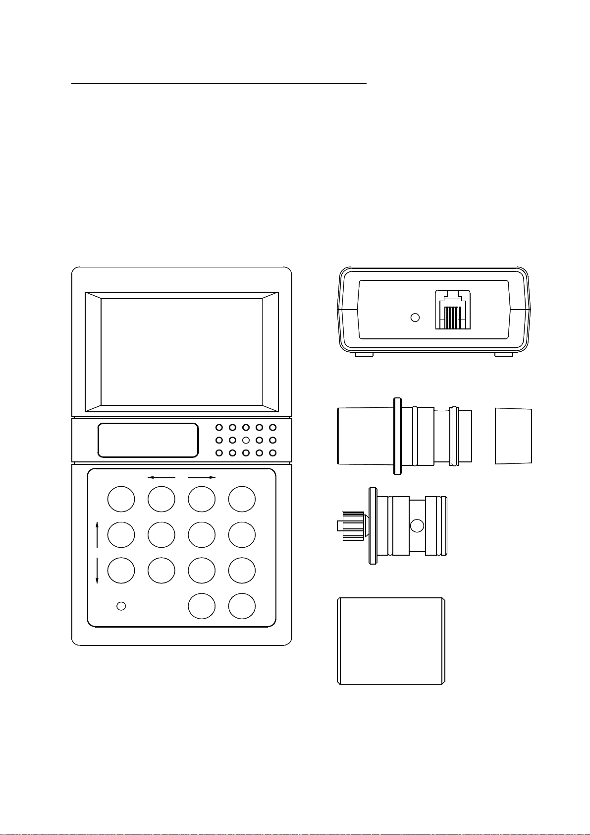
MicroRint Microcomputer - System Overview (Fig. 1)
Fig. 1
The Micro Medical MicroRint is a data recording airways resistance meter consisting of a
microcomputer unit (1) incorporating an LCD graphic display, data entry keypad, RS232 serial
interface and all associated circuitry. This is supplied with an interrupter transducer (2), resistive
element holder (3) resistive element (4) Pressure calibration adapter (5) and Mouthpiece adapter (6).
The MicroRint is powered by internal rechargeable Nickel Cadmium cells or by the mains adapter
supplied.
The interrupter transducer is used to measure the subject’s airways resistance in accordance with the
operating manual.
MicroRint
2
CHARGING
1
MicroRint
S
C
1
A
L
E
4 5
7 8
CHARGING
SCROLL
2
3
6
9
0
ON
OFF
DELETE
ENTER
3 4
5
6
2
Page 4
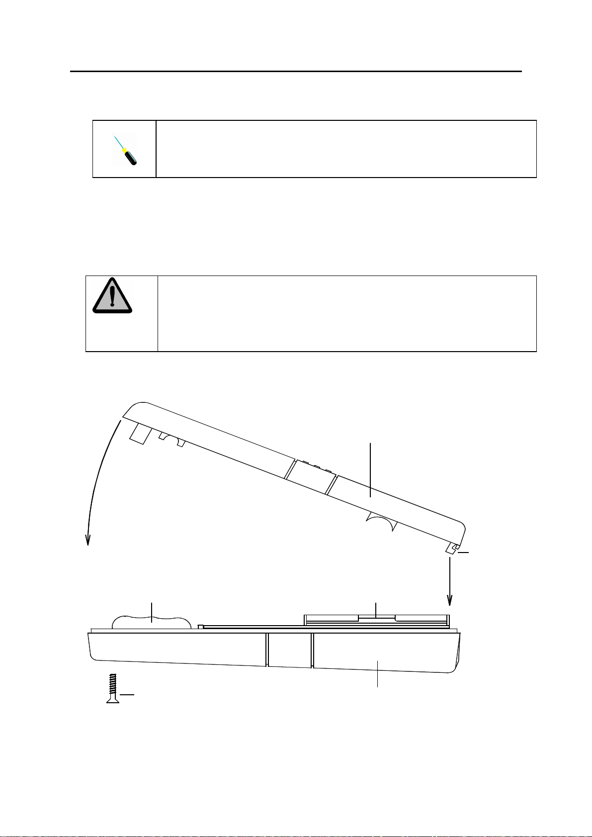
Disassembling the MicroRint Computer for Circuit Investigation
1. Disconnect all mains power supplies
We recommend that you use a Philip Number Zero screwdriver for the
following instruction.
2. Place the MicroRint face down to remove the two screws in the lower moulding, and put the
screws to one side.
3. Turn the unit face up and ease the upper and lower mouldings apart by lifting the top moulding at
an angle as illustrated in the diagram below until it becomes loose.
4. Reconnect mains power supply
5. The MicroRint is now ready for Circuit Investigation.
If you are not familiar with the operation of the MicroRint please read the
following section in this manual ‘Circuit Description’ and use the Circuit
diagrams at the back of this manual.
Top moulding
Locating
lugs
Battery pack
2 off screws
Display
Bottom moulding
3
Page 5
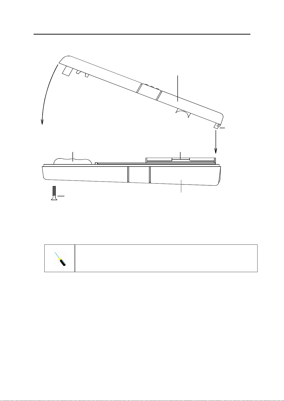
Reassembling the MicroRint Computer for Ready for Operation
Top moulding
Locating
lugs
Battery pack
2 off screws
1. Replace printed circuit board (If removed during investigation) into the bottom moulding.
2. Place the top moulding locating lugs into the bottom moulding at an angle as illustrated above.
3. Push the top moulding together with the bottom moulding making sure that there are no wires
caught between the top and bottom moulding.
We recommend that you use a Philip Number Zero screwdriver for the
following instruction.
4. Turn the unit face down and insert the two screws into the bottom moulding and secure.
5. The unit will now require calibration - Refer to operating manual.
Display
Bottom moulding
4
Page 6
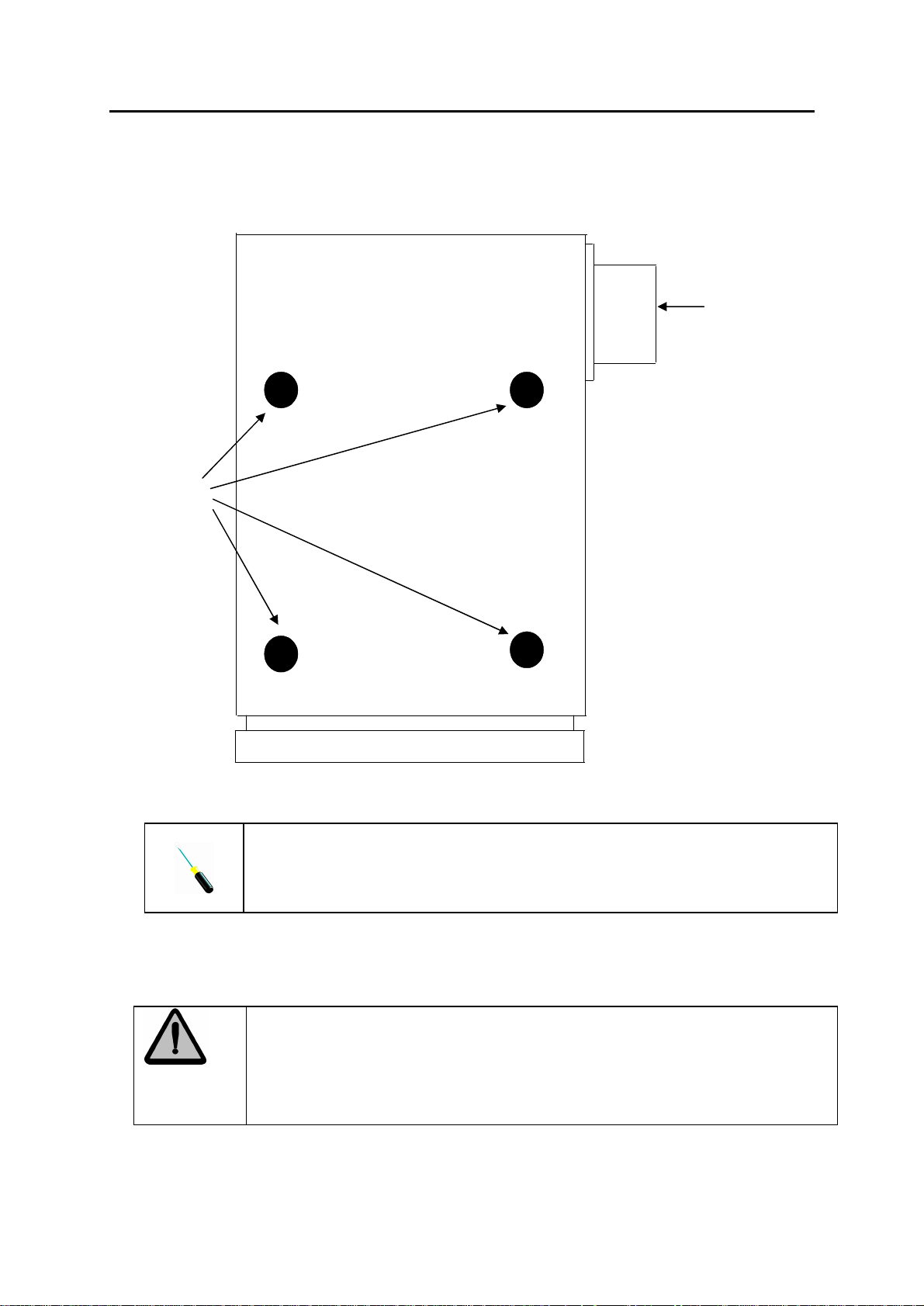
Disassembling the Interrupter Transducer for Circuit Investigation
1. Disconnect the Interrupter Transducer from the MicroRint Computer
2. Remove the Resistive element holder and put to one side.
3. Remove the four rubber feet and put to one side.
RESISTIVE
ELEMENT
HOLDER
FOUR
RUBBER
FEET
Fig 2
We recommend that you use a Philip Number Zero screwdriver for the
following instruction.
4. Remove the four screws located under the rubber feet and put to one side.
5. Ease the moulding apart to reveal the circuitry.
6. The Interrupter Transducer is now ready for fault finding.
If you are not familiar with the operation of the MicroRint please read the
following section in this manual ‘Circuit Description’ and use the Circuit
diagrams at the back of this manual.
5
Page 7

Reassembling Interrupter Transducer
FOUR
RUBBER
FEET
RESISTIVE
ELEMENT
HOLDER
1. Push the two mouldings together ensuring that no tubing is caught between the two mouldings.
We recommend that you use a Philip Number Zero screwdriver for the
following instruction.
2. Replace the four screws into the moulding and secure
3. Replace the four rubber feet over the screws as shown above.
4. Push the resistive element holder into the Interrupter transducer.
5. The unit will now require calibration – Refer to operating manual.
6
Page 8

Circuit Description – Microcomputer
(Refer to Drawing (047-01)
Overview
The microprocessor control circuit carries out the spirometry routines, monitors the transducer
operation and keypad, and drives the display under the control of the program stored in the battery
backed RAM.
The power supply uses the mains adapter, internal Nickel-Cadmium (Ni-Cad) cells and an internal
lithium backup as its sources of energy. The supply provides 5 volts to the control circuit, -12 volts
supply for the display and RS232 driver circuit, 3 volts RAM backup, controls the charging current to
the Ni-Cad battery pack, and provides for battery management.
The microprocessor (IC1) communicates with the real time clock (IC6), the output latch (IC5), and the
display under the control of the program, stored in the RAM (IC2), using a multiplexed address and
data bus decoded by a data latch (IC3). The RAM, which is used both for program storage and for
temporary data storage, has a memory map which is partitioned by the action of the PAL (IC4) into
writable and non-writable areas.
Address bus
The microprocessor (IC1) uses a multiplexed address bus. The lower order address lines are latched
into IC3 with the address strobe (AS).
The program for the microprocessor (IC1) is stored in a 128kByte, battery backed static ram, (IC2).
As the address space of the processor is limited to 64kBytes the ram address space is paged using a
programmable array logic device (IC4). This device decodes address lines A1, A13, A14, A15, port
lines PD5, PA4, control line R/W, clock signal E, mode control lines MODA, MODB, and the external
reset line to provide the following outputs:
RAM address lines A15 and A16
Chip select lines (CS) for the display and latch (IC5)
Write enable (WR) for display, latch, and RAM
Read enable (RD) for the display
Output enable (OE) for the RAM
Reset
The reset circuit consists of a single chip reset (IC9) which holds the reset line (RES) low for 350ms
after the 5 volt supply has reached the threshold voltage of 4.5 volts. The reset signal is applied to the
microprocessor (IC1), display, programmable array logic device (IC4), and the printer driver processor
(IC17).
Keypad
The 12 keypad switches ( 0 to 9, ENTER and DELETE) are arranged in a 3 column by 4 row matrix.
When the keypad is being read by the processor the 3 columns are sequentially driven high by the
output latch (IC5 pins 19,16 and 15). The state of the 4 rows is read by the general purpose port PE4
to PE7 of the processor. The diodes in the package D2 isolate the outputs from IC5 to ensure that a
high current will not flow from an output set high to one set low if two keys are pressed
simultaneously. The ON and OFF keys are connected to the power control circuitry described in the
Power Supply section.
7
Page 9

Real Time Clock
The real time clock (IC6) is set by the processor during the factory set-up and may be set to the local
time zone –see operating manual. The processor communicates with the real time clock (RTC) with a
serial interface line to pin 5 of the RTC. The RTC is selected by the signal from pin 12 of the output
latch (IC5).
Display
The display is a custom graphic 128 by 64 dot LCD with in-built control circuitry. The contrast is
adjusted by varying the voltage on pin 3 between –6.5 and -11 volts with VR1. This potentiometer
varies the output of the voltage inverter, IC12.
Battery monitoring
The microprocessor contains eight, 8 bit analogue to digital converters. One of these, AN3 is used to
monitor the condition of the main supply (BAT1). The main supply is monitored at the input to the logic
5-volt regulator (IC11) and the user will be alerted to a low battery condition when the voltage falls
below 6 volts. The voltage is divided by two with R8 and R9 to bring the voltage within the range of
the A/D converter (5 volts). AN3 also detects when the external power supply has been applied. One
end of R10 is pulled to 0 volts when the external supply is not applied and the voltage read on the A/D
converter will be up to 4 volts for a fully charged battery. With the external supply applied, the voltage
will rise above 5 volts.
Power Supply
The power supply consists of linear 9 volt and 5 volt regulated supplies (IC7 and IC11), an adjustable
switching regulator (IC12) and a lithium backup battery (BAT2), together with the NI-CAD charging
circuit and low battery detector. The 9 volt regulator, IC7, is only operational when the mains adapter
is connected and effectively replaces the 7.2 volt battery pack (BAT1) as the two supplies are
connected through the dual diode D6. During this time the battery pack is trickle charged from the
external supply by the 25mA constant current source formed by TR6, D1, R4, and R7. The bridge
diode network, D4, provides protection against reverse polarity on the external supply. The inductors
L1 and L2 provide attenuation of conducted noise to the external supply. The terminal voltage of the
battery pack is monitored by an analogue input of the processor, AN3, through the potential divider
network formed by R8 and R9. R8 is connected to the 9 volt supply, which is only active when the
external supply is in use. The processor can detect when the external supply is in use as the
analogue input will rise to above full scale, 5 volts, when this occurs. The input to the 5-volt regulator
(IC11), and the voltage inverter (IC12), is controlled by TR5, which is turned on when the output of
IC10 A is high. IC10 (gates A and B) form a bi-stable latch controlled by the ON and OFF switches on
the keypad or by the microprocessor via TR1 and TR7.
8
Page 10

Circuit Description – Interrupter Transducer
(Refer to Drawing 046-10)
Overview
During measurement the interrupt transducer monitors tidal flow and provides for a means of
momentary airways occlusion during which time the pressure at the mouth is measured.
The flow is measured by monitoring the pressure across a resistive element using a high frequency
silicon solid state sensor.
Occlusion is provided by a fast acting rotary solenoid attached to a shutter. During occlusion the
pressure sensor is used to monitor the pressure developed at the mouth.
Power supply
The power supply consists of a voltage converter (IC6) which produces a 12v supply, an adjustable
regulator configured so as to produce a 10V supply for the pressure monitor circuit and a linear 5V
regulator (IC4).
The rechargeable Ni-cad battery pack is trickle charged from the 12V supply through R5 and D3. TR3,
R6 and R7 are not used.
Battery Monitor
The comparator (IC1A) compares a reference voltage (IC1A Pin 6) to the voltage developed across
the current sensing resistor (R9) when the shutter solenoid (M1) is activated. The output from this
comparator (Pin 7) is used to shutdown the A/D converter (IC5) when insufficient current is passing
through R9 during solenoid activity indicating a discharged battery. The Microcomputer unit will detect
that the A/D converter is shutdown during operation and will indicate a battery low condition to the
user on the LCD display.
Pressure Monitor
During solenoid operation the differential output of the pressure transducer (PT1) is applied to the
instrumentation amplifier configuration of IC2. The output from this amplifier is applied to the analogue
input of the A/D. Serial data is clocked out of the A/D by the SCLK input when CS is low.
Shutter Operation
The shutter solenoid is energised when the trigger input is taken to 5V, turning on TR1 and TR2.
When the valve is de-energised the shutter returns to the open position by the action of the internal
spring.
9
Page 11

Parts List - Microcomputer
Designation
IC1
IC2
IC3
IC4
IC5
IC6
IC7
IC8
IC9
IC10
IC11
IC12
IC15
R1 100K SURFACE MOUNT RESISTOR 0.125 WATT 5% SIZE 1206
R2 1M SURFACE MOUNT RESISTOR 0.125 WATT 5% SIZE 1206
R3 1K SURFACE MOUNT RESISTOR 0.125 WATT 5% SIZE 1206
R4 27 OHMS SURFACE MOUNT RESISTOR 0.125 WATT 5% SIZE 1206
R5 330 OHMS SURFACE MOUNT RESISTOR 0.125 WATT 5% SIZE 1206
R6 1K SURFACE MOUNT RESISTOR 0.125 WATT 5% SIZE 1206
R7 10K SURFACE MOUNT RESISTOR 0.125 WATT 5% SIZE 1206
R8 100K SURFACE MOUNT RESISTOR 0.125 WATT 5% SIZE 1206
R9 100K SURFACE MOUNT RESISTOR 0.125 WATT 5% SIZE 1206
R10 100K SURFACE MOUNT RESISTOR 0.125 WATT 5% SIZE 1206
R11 100K SURFACE MOUNT RESISTOR 0.125 WATT 5% SIZE 1206
R12 100K SURFACE MOUNT RESISTOR 0.125 WATT 5% SIZE 1206
R13 1K SURFACE MOUNT RESISTOR 0.125 WATT 5% SIZE 1206
R14 33K SURFACE MOUNT RESISTOR 0.125 WATT 5% SIZE 1206
R15 330K SURFACE MOUNT RESISTOR 0.125 WATT 5% SIZE 1206
R16 10K SURFACE MOUNT RESISTOR 0.125 WATT 5% SIZE 1206
R17 10K SURFACE MOUNT RESISTOR 0.125 WATT 5% SIZE 1206
R18 4.7K SURFACE MOUNT RESISTOR 0.125 WATT 5% SIZE 1206
R19 4.7K SURFACE MOUNT RESISTOR 0.125 WATT 5% SIZE 1206
R20 3.3K SURFACE MOUNT RESISTOR 0.125 WATT 5% SIZE 1206
R21 3.3K SURFACE MOUNT RESISTOR 0.125 WATT 5% SIZE 1206
R22 3.9K SURFACE MOUNT RESISTOR 0.125 WATT 5% SIZE 1206
R23 1K SURFACE MOUNT RESISTOR 0.125 WATT 5% SIZE 1206
R24 100 OHMS SURFACE MOUNT RESISTOR 0.125 WATT 5% SIZE 1206
R25 1M SURFACE MOUNT RESISTOR 0.125 WATT 5% SIZE 1206
RN1 4 WAY COMMONED 10K SIL NETWORK
VR1
C1 RUBYCON 22uF 35 VOLT ELECTROLYTIC CAPACITOR TYPE 35MH522M0563
C2 RUBYCON 47uF 16 VOLT ELECTROLYTIC CAPACITOR TYPE 16MH547M6357
C3 RUBYCON 47uF 16 VOLT ELECTROLYTIC CAPACITOR TYPE 16MH547M6357
C4 RUBYCON 47uF 16 VOLT ELECTROLYTIC CAPACITOR TYPE 16MH547M6357
C5 RUBYCON 47uF 16 VOLT ELECTROLYTIC CAPACITOR TYPE 16MH547M6357
C6 RUBYCON 47uF 16 VOLT ELECTROLYTIC CAPACITOR TYPE 16MH547M6357
C7 RUBYCON 47uF 16 VOLT ELECTROLYTIC CAPACITOR TYPE 16MH547M6357
C8 RUBYCON 47uF 16 VOLT ELECTROLYTIC CAPACITOR TYPE 16MH547M6357
C9 10nF PHILIPS SURFACE MOUNT CERAMIC CAPACITOR SIZE 1206
C10 15pF PHILIPS SURFACE MOUNT CERAMIC CAPACITOR SIZE 1206
C11 10nF PHILIPS SURFACE MOUNT CERAMIC CAPACITOR SIZE 1206
(MC68HC11E1FN) MICROCONTROLLER
(KM681000BLG/BLG-L) SAMSUNG 1 MEG SURFACE MOUNT STATIC RAM
55 TO 150nS ACCESS TIME
(74HC573) SURFACE MOUNT OCTAL LATCH
(PALCE16V8Z25PC) AMD ZERO POWER CMOS PLD DIP PACKAGE
(74HC273) SURFACE MOUNT OCTAL D FLIP-FLOP
(PCF8583T) PHILIPS SURFACE MOUNT CLOCK CALENDER WITH 256 BYTE RAM
(LM2940T-9.0) LOW DROP OUT 9 VOLT 1 AMP REGULATOR
(74HC14) SURFACE MOUNT HEX SCHMITT INVERTOR
(DS1233D-10) DALLAS ECONO RESET
(4093) SURFACE MOUNT QUAD NAND GATE
(LM2931M-5.0) LOW DROP OUT 5 VOLT 100mA SURFACE MOUNT REGULATOR
(LT1054CS8) SURFACE MOUNT VOLTAGE CONVERTOR
(BU4S11) OR (BU4S01) RHOM INDIVIDUAL CMOS GATE
(T18 S/I S/B S/T 20KA) PHIER 20K LINEAR POTENTIOMETER
Description
10
Page 12

C12 10nF PHILIPS SURFACE MOUNT CERAMIC CAPACITOR SIZE 1206
C13 33pF PHILIPS SURFACE MOUNT CERAMIC CAPACITOR SIZE 1206
C14 33pF PHILIPS SURFACE MOUNT CERAMIC CAPACITOR SIZE 1206
C15 1nF PHILIPS SURFACE MOUNT CERAMIC CAPACITOR SIZE 1206
C16 1nF PHILIPS SURFACE MOUNT CERAMIC CAPACITOR SIZE 1206
CD (X7) 100nF PHILIPS SURFACE MOUNT CERAMIC CAPACITOR SIZE 1206
TR1
TR2
TR3
TR4
TR5
TR6
TR7
LED T1/3mm ORANGE LED
D1
D2
D3
D4
D5
D6
D7
D8
D9
L1
L2
DISPLAY
SK1
SK2
SK3 10 WAY PIN HEADER
SK4
SK5
SPKR
X1 4.9152MHz CRYSTAL CAN STYLE HC49/4H
X2 32.768KHz CRYSTAL
BAT1 NI-CAD BATTERY PACK - 6 X AAA CELLS
BAT2
(DTC114EK) RHOM NPN DIGITAL TRANSISTOR
(DTC114EK) RHOM NPN DIGITAL TRANSISTOR
(DTB113EK) RHOM PNP DIGITAL TRANSISTOR
(DTA114EK) RHOM PNP DIGITAL TRANSISTOR
(FMMT591) ZETEX PNP TRANSISTOR - SOT23
(2SB1189) RHOM PNP TRANSISTOR - MPT (SOT89)
(DTC114EK) RHOM NPN DIGITAL TRANSISTOR
(IMN10) RHOM 3 DIODE ARRAY - IMD PACKAGE
(IMN10) RHOM 3 DIODE ARRAY - IMD PACKAGE
(IMN10) RHOM 3 DIODE ARRAY - IMD PACKAGE
(S1NB20) SHINDENGEN 1A BRIDGE RECTIFIER
(1SR154-400) RHOM 1A DIODE - PSM PACKAGE. ALTERNATIVE SHINDENGEN (D1F20)
(S1ZAS4) SHINDENGN 1.2A DUAL SCHOTTKY DIODE
(S1ZAS4) SHINDENGN 1.2A DUAL SCHOTTKY DIODE
(BAS19) SMALL SIGNAL DIODE SOT23 PACKAGE
(ZHCS750) ZETEX SMALL SIGNAL SCHOTTKY DIODE SOT23 PACKAGE
(NLC565050T-3R9K) TDK 3.9uH SURFACE MOUNT INDUCTOR
(NLC565050T-3R9K) TDK 3.9uH SURFACE MOUNT INDUCTOR
(DMF-50424N) OPTREX 128 X 64 GRAPHIC DISPLAY
(MDS4) 4 WAY MINI DIN SOCKET
(95001-2611) MOLEX 6 WAY DATA SOCKET
(MJ-179P) DC POWER SOCKET
(B 3B-PH-SM3-TB) 3 WAY PCB SOCKET FROM JST
(PKM35-4A0) MURATA PIEZO CERAMIC SOUNDER
(CR2040) 280mA-Hr 3V LITHIUM PCB MOUNTED BATTERY
11
Page 13

Parts List - Interrupter Transducer
Designation
IC1
IC2
IC3
IC4
IC5
IC6
IC7
IC8
TR1
TR2
TR3 NOT USED
R1 100K SURFACE MOUNT RESISTOR 0.125 WATT 5% SIZE 1206
R2 1.8K SURFACE MOUNT RESISTOR 0.125 WATT 5% SIZE 0805
R3 10K SURFACE MOUNT RESISTOR 0.125 WATT 5% SIZE 0805
R4 47 OHM SURFACE MOUNT RESISTOR 0.125 WATT 5% SIZE 0805
R5 680 OHM SURFACE MOUNT RESISTOR 0.125 WATT 5% SIZE 1206
R6 NOT USED
R7 NOT USED
R8 1M SURFACE MOUNT RESISTOR 0.125 WATT 5% SIZE 1206
R9 0.1 OHM 0.25 WATT RESISTOR
R10 100K SURFACE MOUNT RESISTOR 0.125 WATT 5% SIZE 1206
R11 6.8K SURFACE MOUNT RESISTOR 0.125 WATT 5% SIZE 1206
R12 100K SURFACE MOUNT RESISTOR 0.125 WATT 5% SIZE 1206
R13 100K SURFACE MOUNT RESISTOR 0.125 WATT 5% SIZE 1206
R14 33K SURFACE MOUNT RESISTOR 0.125 WATT 1% SIZE 1206
R15 4.7K SURFACE MOUNT RESISTOR 0.125 WATT 1% SIZE 1206
R16 10K SURFACE MOUNT RESISTOR 0.125 WATT 1% SIZE 1206
R17 10K SURFACE MOUNT RESISTOR 0.125 WATT 1% SIZE 1206
R18 100K SURFACE MOUNT RESISTOR 0.125 WATT 1% SIZE 1206
R19 100K SURFACE MOUNT RESISTOR 0.125 WATT 1% SIZE 1206
R20 1M SURFACE MOUNT RESISTOR 0.125 WATT 1% SIZE 1206
R21 1M SURFACE MOUNT RESISTOR 0.125 WATT 1% SIZE 1206
R22 100K SURFACE MOUNT RESISTOR 0.125 WATT 1% SIZE 1206
R23 100K SURFACE MOUNT RESISTOR 0.125 WATT 1% SIZE 1206
R24 1.5K SURFACE MOUNT RESISTOR 0.125 WATT 1% SIZE 1206
R25 100K SURFACE MOUNT RESISTOR 0.125 WATT 5% SIZE 1206
R26 10K SURFACE MOUNT RESISTOR 0.125 WATT 5% SIZE 1206
R27 390 OHM SURFACE MOUNT RESISTOR 0.125 WATT 5% SIZE 1206
R28 100K SURFACE MOUNT RESISTOR 0.125 WATT 5% SIZE 1206
R29 1K SURFACE MOUNT RESISTOR 0.125 WATT 5% SIZE 0805
R30 4.7K SURFACE MOUNT RESISTOR 0.125 WATT 5% SIZE 1206
C1 NOT USED
C2 10nF MULTILAYER SURFACE MOUNT CERAMIC CAPACITOR SIZE 1206
C3 10uF16V TANTALUM SURFACE MOUNT CAPACITOR
C4 100uF16V TANTALUM SURFACE MOUNT CAPACITOR
C5 100uF 25 VOLT ELECTROLYTIC CAPACITOR 0.1" PITCH
C6 47uF 16 VOLT ELECTROLYTIC CAPACITOR 0.1" PITCH
C7 100uF 16 VOLT ELECTROLYTIC CAPACITOR 0.1" PITCH
C8 100uF 16 VOLT ELECTROLYTIC CAPACITOR 0.1" PITCH
C9 1nF MULTILAYER SURFACE MOUNT CERAMIC CAPACITOR 5% SIZE 1206
(LM393M) DUAL LOW POWER SURFACE MOUNT COMPARATOR
(OP490GS) QUAD LOW POWER SURFACE MOUNT PRECISION OP-AMP
(LP2951CM) LOW DROP OUT ADJUSTABLE SURFACE MOUNT REGULATOR
(LM2931M-5.0) LOW DROP OUT 5 VOLT SURFACE MOUNT REGULATOR
(MAX187CCWE) SERIAL A/D ALTERNATIVE MAX189 SUFFIX (A,B OR C) CWE
(LT1054CS8) SURFACE MOUNT VOLTAGE CONVERTOR
(BU4S11) OR (BU4S01) INDIVIDUAL CMOS GATE
(ZRT040GC1) 4.01V SURFACE MOUNT REFERENCE (NOT USED WITH MAX187)
(ZTX869) E-LINE NPN TRANSISTOR
(ZTX869) E-LINE NPN TRANSISTOR
Description
12
Page 14

C10 1nF MULTILAYER SURFACE MOUNT CERAMIC CAPACITOR 5% SIZE 1206
C11 10nF MULTILAYER SURFACE MOUNT CERAMIC CAPACITOR SIZE 1206
C12 100pF CERAMIC CAPACITOR 0.1" PITCH
C13 100pF CERAMIC CAPACITOR 0.1" PITCH
C14 100pF CERAMIC CAPACITOR 0.1" PITCH
C15 100pF CERAMIC CAPACITOR 0.1" PITCH
C16 220nF MULTILAYER SURFACE MOUNT CERAMIC CAPACITOR SIZE 1206
D1 GENERAL PURPOSE SURFACE MOUNT 1A DIODE
D2 NOT USED
D3
D4
D5
BAT 5 x 1/3AA SIZE 110mA-hr SANYO BATTERY PACK
PT1
LED LOW CURRENT YELLOW LED
M1
(1N4148) GENERAL PURPOSE SMALL SIGNAL DIODE
(10BQ040) 1A SCHOTTKY SURFACE MOUNT DIODE
(10BQ040) 1A SCHOTTKY SURFACE MOUNT DIODE
(176PC07HD2) HONEYWELL 7" H20 PRESSURE TRANSDUCER
(GDAY 025 X20 B25) EMMESEM ROTARY SOLENOID 6.8V 7% DUTY 1.25 OHMS 65 DEG
13
Page 15

Technical Support
Great Britain and World Headquarters
Micro Medical Ltd
PO Box 6
Rochester
Kent ME1 2AZ
Telephone + 44 (0)1634 360044
Fax +44 (0)1634 360055
Web Site http://www.micromedical.com.uk
Email support@micromedical.com.uk
Contact Micro Medical Ltd for the local agent in your region or country for local service:
14
Page 16

Fault Analysis
The following analysis is only a guideline and should be carried out in a logical sequence. If the fault is
still apparent after the following suggestions then the unit should be fault found using the circuit
descriptions and circuit diagrams provided.
When the unit is turned on there is no display present
-Rotate contrast thumb wheel anti-clockwise to see if screen darkens.
-Connect charger to see if screen darkens and charging light illuminates.
When the unit is turned on the display is dark purple
-Rotate contrast thumb wheel clockwise to see if screen colour becomes lighter and characters are
displayed.
-Connect charger to see if screen characters appear.
The recorded values are low
-Ensure that the unit is calibrated – Refer to operating manual.
-Ensure that the mouthpiece holder is fully inserted into the interrupter transducer unit.
-Check that the resistive element is not damaged.
The shutter does not activate
-Check that the battery low message is not displayed on the LCD display
-Ensure that the interrupter transducer is connected to the microcomputer unit.
15
Page 17

16
Page 18

17
 Loading...