

Page 1

Contents page
Safety Precaution 3
Important safeguards 3
Looking after your
Micro/Micro Plus 3
Introduction 3
Before you begin 3
Micro/Micro Plus
system Overview 4
Micro Medical
Digital Volume
Transducer 5
Cleaning the Micro
Medical Digital
Volume Transducer 6
Micro/Micro Plus
exploded view 7
Disassembling the
Micro/Micro Plus for
Circuit Investigation 8
Reassembling the
Micro/Micro Plus 9
Circuit description 10
Technical Data 12
Technical support 13
Parts List 14
Circuit Diagram 15
Micro/Micro Plus
Service Manual
051-07 Iss. 1.0 September 1998
Page 2

Micro/Micro Plus
Service Manual
Information in this document is subject to change without notice and does not represent a
commitment on the part of Micro Medical Limited. Only the parts supplied by Micro Medical
Limited should be used to complete the service operation described in this manual. If in any
way you feel unsure about the successful completion of the service operation you should
contact Micro Medical Limited or its appointed agent in your country or region and arrange the
despatch of the product to a Micro Medical Limited Service Centre.
Copyright 1998 by Micro Medical Limited All rights reserved
Drawing no. 051Version 1.0
September 1998
All other products are trademarks or registered trademarks of their respective owners.
2
Page 3

Safety Precaution
The servicing of this device is intended to be carried out by a properly
trained and competent electronics engineer, or experienced in the
maintenance and servicing of medical devices. Read this manual
thoroughly before proceeding with the service. If in any doubt please
contact the service centre at Micro Medical Limited or their accredited
agent in your country or region.
Important Safeguards
o Read all of the instructions.
o Keep the instructions in a safe place for later use.
o Follow all warnings and instructions marked on the product.
o When replacement parts are required, be sure to use replacement parts
specified by Micro Medical that have the same characteristics as the
original parts. Unauthorised substitutions may result in fire, electric or
other hazards.
o Do not place on an unstable table.
o The product should be operated only from the type of power source
indicated on the label.
Looking after your Micro/Micro Plus Spirometer
o Avoid exposing the Micro/Micro Plus Spirometer to direct sunlight.
o Avoid operating the spirometer in dusty conditions or near to heating
appliances or radiators.
o Do not keep the spirometer in a damp place or expose it to extreme
temperatures.
o Do not direct the transducer holder towards a strong light source whilst
operating the spirometer.
Introduction
This service manual provides you with information to carry out the
servicing operation of the Micro/Micro Plus Spirometer. should the unit
become faulty It is a process, which is relatively straightforward but must
be carried out in a logical sequence. Our advice is to familiarise yourself
with the contents of this manual before attempting to carry out the
procedure of replacing the parts supplied in the service kit for the
Micro/Micro Plus Spirometer.
Before You Begin
Before you begin the servicing operation, please read the section on
Circuit description very carefully:
3
Page 4
M
e
d
i
c
a
l
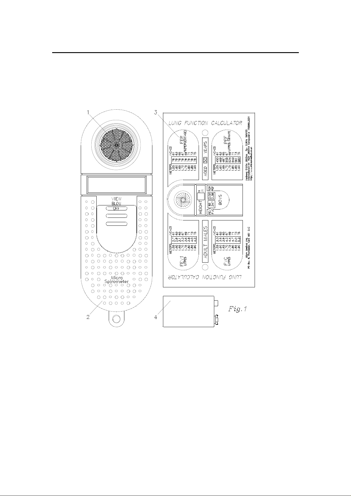
Micro/Micro Plus system overview.
The Micro Medical Micro/Micro Plus Spirometer consists of a hand held
microcomputer unit (2) incorporating a Micro Medical digital volume
transducer (1).
o
r
c
i
M
1. Micro Medical Digital Volume Transducer.
2. Micro microcomputer unit.
3. Lung Function Calculator.
4. PP3 Alkaline battery (BAT2).
4
Page 5
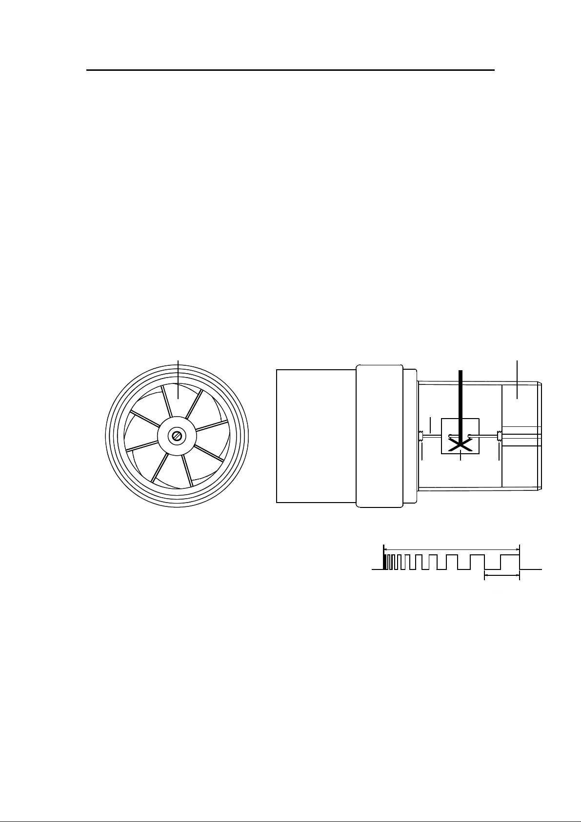
Micro Medical Digital Volume Transducer
VOLUME PROPORTIONAL TO THE NUMBER OF PULSES
FLOW PROPORTIONAL TO THE PULSE FREQUENCY
The Micro Medical digital volume transducer consists of an acrylic tube
with a vane (3) positioned between a stator (1) and a cross bar (2). The low
inertia vane is attached to a stainless steel pivot (5) which is free to rotate on
two jewelled bearings (4) mounted at the centre of the stator plate and cross
bar. As air is passed through the transducer a vortex is created by the stator,
which causes the vane to rotate. The number of rotations is proportional to
the volume of air passed through the transducer and the frequency of rotation
is proportional to the flow rate. The transducer passes through the PCB,
which contains a light emitting diode (LED) and phototransistor. The LED
produces an infrared beam, which is interrupted by the vane twice per
revolution. This interruption is sensed by the phototransistor giving a square
wave output on the collector.
There is no routine maintenance required for the transducer other than
cleaning.
434
Flow
k/pulse
2
1
INFRA RED
EMITTER
5
INFRA RED
DETECTOR
Volume = k X No. of
5
Page 6

Cleaning the Digital Volume Transducer
The transducer requires no routine maintenance or servicing. However if you
wish to sterilise or clean the transducer it may be removed by the following
procedure.
1. Remove the transducer by gently pulling from the main body with a
twisting action.
2. The transducer may now be immersed in warm soapy water for routine
cleaning or immersed in a cold sterilising solution e.g. Alkacide for a period
not exceeding 15 minutes. (Alcohol and chloride solutions should be
avoided.)
3. After cleaning or sterilising, the transducer should be rinsed in distilled
water and dried.
4. Reassemble the transducer into the Micro/Micro Plus Spirometer.
Alkacide is available from Micro Medical in convenient 250ml plastic
bottles (Cat No. SSC1000)
6
Page 7

Micro/Micro Plus Spirometer exploded view (fig 1)
Item 8
Item 4Item 5
Item 6
Item 7
Item 1
Item 3
Item 8
1. Bottom Moulding 2. Top Moulding
3. PCB Assembly 4. Turbine sleeve
5. Coated O ring 6. O ring capture ring
Item 2
7. Polycarbonate window 8. 2 x Screws
7
Page 8

Disassembling the Micro/Micro Plus for Circuit Investigation.
If the Micro/Micro Plus Spirometer becomes faulty then the following
procedure is needed to investigate the fault.
1 Remove the digital volume transducer from the microcomputer unit by
gently pulling the transducer from the microcomputer unit with a twisting
action.
2 Turn the unit face down and slide back the battery cover.
3 Remove the battery and place to one side.
4 Remove the 2 screws on the bottom moulding.
5 Turn the Micro/Micro Plus face up and ease the top moulding from the
bottom and turn the top moulding over so as the unit is in two halves.
6 Remove the PCB from the bottom moulding and put the bottom
moulding to one side.
7 The Micro/Micro Plus is now ready for fault finding
8
Page 9

Reassembling the Micro/Micro Plus
1. Place the PCB into the bottom moulding and wire battery lead as as
shown in fig 2.
2. Replace items 4, 5 and 6 (Fig1) into the bottom moulding.
3. Position top moulding on top of bottom moulding and push together
(ensure that the battery leads are not trapped).
4. Turn unit face down and replace the 2 screws.
5. Replace the PP3 battery ensuring correct polarity.
6. Replace the battery cover.
7. Turn the unit face up and refit transducer into the microcomputer unit.
8. The unit is now ready for operation.
Fig 2
9
Page 10

Circuit description
The circuit is based on the Motorola one time programmable (OTP)
microcontroller MC68HC705C9ACFN (IC1) operating at a clock frequency
of 1 MHz. This processor contains 7 Kbytes of EPROM, 176 Bytes of
RAM, programmable output latches, and a serial peripheral interface (SPI).
The processor monitors pulses from the transducer, calculates the
spirometry measurements, and directly drives the LCD display according
to the position of the slide switch. The state of the battery is also
monitored and a warning is displayed when necessary. Calibration
information is stored in a 256 bit serial EEPROM, IC5, and communicates
with the microcontroller via the SPI.
Reset
The reset circuit consists of a single chip reset (IC7) which holds the reset
line low for 350ms after the 5 volt supply has reached the threshold
voltage of 4.5 volts. The reset signal is then applied to the microprocessor
(IC1),
Power Supply
The unit is powered an alkaline 9 volt PP3 battery (BAT1) and switched by
IC3 which is arranged in a bi-stable configuration. When the unit is turned
on via the slide switch a momentary pulse appears on pin 1 of IC3 by the
action of R8, R9 and C10. This pulse toggles the bi-stable circuit so that
pin 11 of IC3 will go low turning transistor TR4 on and supplying 9 volts to
the low drop out regulator (IC4). When the unit is turned off pin 13 of IC3
is pulled low reversing the bi-stable action and turning TR4 off. If the unit
is left on without use for 6 minutes then pin 31 of IC1 is driven high under
software control turning on TR5 which will turn the unit off via the bi-stable
circuit.
Battery monitoring
The terminal voltage of the battery is monitored by the action of R4, R5,
R6, and TR2. The emitter of TR2 is held at 5 volts and the base voltage is
derived from the battery through the potential divider formed by R4 and
R5. When the battery voltage falls to approximately 6 volts, the voltage on
the base of TR2 is 4.4 volts and the transistor turns on. The collector will
rise to about 4.6 volts and this is monitored by the processor on pin 13
(PB0) when the unit is switched on. When a low battery condition is
detected the processor signals to the user that the battery is low by
flashing the letters bat three times on the display accompanied by an
audible warning.
10
Page 11

Display
The display is a custom 3½ digit low power LCD. The seven segments of
three digits are driven directly by ports A, B and C of the microcontroller
with port PA0 driving the back plane. The decimal point, “1” digit, and the
other legends are driven by the 8 bit shift register, IC2, which is controlled
by the microcontroller via the SPI interface. The back plane is driven by a
square wave of nominally 60 Hz. The individual segments are driven by a
similar square wave, which is in phase with the backplane when the
segment is off and 180 degrees out of phase when the segment is on.
Serial Interface (Micro Plus unit only)
Serial communications are established from the microprocessor to the
external RS232 port using its serial communications interface (IC6)
Transducer interface
The rotation of the vane inside the transducer is sensed by the interruption
of an infrared beam produced by the LED and sensed by the
phototransistor. The LED is controlled by the emitter follower (TR1) and is
only energised during a spirometry test when the BLOW legend on the
display is showing.
The light beam is detected by the phototransistor, which is in common
emitter configuration. The load resistor is factory adjusted using VR1 to
give the largest collector swing when the turbine is subjected to a flow or
air at 37 degrees Celsius saturated with water vapour. VR1 is factory set
and should not be adjusted by the user. The signal at the collector is
conditioned by the action of the schmitt inverter (IC3) and applied to the
pulse capture input of the microcontroller (Pin 42 of IC1). The
microcontroller calculates the expired volume and flow from the number
and rate of received pulses.
Calibration
The sensitivity of the Micro Medical digital volume transducer depends
only upon the fixed geometry of the stator and is inherently stable. The
calibration will be unaffected by any dirt which may build up on the stator
due to poor cleaning procedures. However, physical damage to stator
may adversely affect calibration and in this instance the unit should be
returned to Micro Medical for transducer replacement and re-calibration.
At Micro Medical calibration is performed with a computer controlled
waveform generator, approved by the American Thoracic Society.
11
Page 12

Technical Data
Transducer Type
Micro Medical Uni-Directional Digital Volume
Resolution
10ml
Accuracy
+/-3%.(To ATS recommendations Standardisation of Spirometry 1994
update for flows and volumes).
Volume Range
0.1-9.99 litres B.T.P.S
Flow Range
30L/min-1000L/min
Display
Custom 3½ digit Liquid crystal
Power Supply
9V PP3 dry cell
Dimensions
170 x 60 x 70mm (including transducer)
Weight
Unit only: 150g
Unit and accessories: 550g
Operating temperature
0 to +40°C
Operating Humidity
30% to 90% RH
Storage Temperature
-20 to +70°C
Storage Humidity
10% to 90% RH
12
Page 13

Technical Support
Great Britain and World Headquarters
Micro Medical Ltd
PO Box 6
Rochester
Kent ME1 2AZ
Telephone + 44 (0)1634 360044
Fax +44 (0)1634 360055
Web Site http://www.micromedical.com.uk
Email support@micromedical.com.uk
Contact Micro Medical Ltd for the local agent in your region or
country for local service:
13
Page 14

Parts List
Designation
IC1
IC2
IC3
IC4
IC5
IC6
IC7
TR1
TR2
TR3
TR4
TR5
LED
D1
DISPLAY 3½ DIGIT CUSTOM DISPLAY
R1 2.2M SURFACE MOUNT RESISTOR 0.1 WATT 5% SIZE 0805
R2 120 OHM ¼ WATT 5% RESISTOR
R3 1K SURFACE MOUNT RESISTOR 0.1 WATT 5% SIZE 0805
R4 33K SURFACE MOUNT RESISTOR 0.1 WATT 5% SIZE 0805
R5 100K SURFACE MOUNT RESISTOR 0.1 WATT 5% SIZE 0805
R6 100K SURFACE MOUNT RESISTOR 0.1 WATT 5% SIZE 0805
R7 100K SURFACE MOUNT RESISTOR 0.1 WATT 5% SIZE 0805
R8 1M SURFACE MOUNT RESISTOR 0.1 WATT 5% SIZE 0805
R9 1M SURFACE MOUNT RESISTOR 0.1 WATT 5% SIZE 0805
R10 100K SURFACE MOUNT RESISTOR 0.1 WATT 5% SIZE 0805
R11 10K SURFACE MOUNT RESISTOR 0.1 WATT 5% SIZE 0805
R12 100K SURFACE MOUNT RESISTOR 0.1 WATT 5% SIZE 0805
R13 10K SURFACE MOUNT RESISTOR 0.1 WATT 5% SIZE 0805
VR1 20K SINGLE TURN POTENTIOMETER
C1
C2
C3 47pF CERAMIC CAPACITOR SIZE 1206
C4 47pF CERAMIC CAPACITOR SIZE 1206
C5
C6
C7
C8
C9 0.1µF SURFACE MOUNT MULTILAYER CERAMIC SIZE 0805
C10 0.1µF SURFACE MOUNT MULTILAYER CERAMIC SIZE 0805
SK1
PL1
SW1
SPKR
BAT1 DURACELL PROCELL PP3 9V BATTERY
X1 4MHZ CERAMIC RESONATOR
TP1 1mm PRESS FIT TERMINAL POST
TP2 1mm PRESS FIT TERMINAL POST
(MC68HC705C9ACFN) MOTOROLA SURFACE MOUNT OTP MICROCONTROLLER
(74HC164) 8 BIT SURFACE MOUNT SERIAL TO PARALLEL SHIFT REGISTER
(4093) SURFACE MOUNT QUAD SCHMITT NAND GATE
(LM2931M-5.0) LOW DROP OUT LOW POWER SURFACE MOUNT 5 VOLT REGULATOR
(93C06) 256 BIT SERIAL SURFACE MOUNT EEPROM
(MAX3221CAE) SURFACE MOUNT RS232 TRANSCEIVER (MICRO PLUS ONLY)
(DS1233D-10) DALLAS ECONO RESET
(DTB113EK) RHOM PNP DIGITAL TRANSISTOR
(FMMT591) ZETEX PNP TRANSISTOR
(SDP8405) HONEYWELL PHOTOTRANSISTOR
(FMMT591) ZETEX PNP TRANSISTOR
(DTC114EK) RHOM NPN DIGITAL TRANSISTOR
(SEP8705) HONEYWELL INFRA RED LED
(BAT42) GENERAL PURPOSE SCHOTTKY DIODE
(16MH547M6357) RUBYCON 47µF 16 VOLT ELECTROLYTIC CAPACITOR
(16MH547M6357) RUBYCON 47µF 16 VOLT ELECTROLYTIC CAPACITOR
0.33µF SURFACE MOUNT MULTILAYER CERAMIC SIZE 0805 (MICRO PLUS ONLY)
47nF SURFACE MOUNT MULTILAYER CERAMIC SIZE 0805 (MICRO PLUS ONLY)
0.33µF SURFACE MOUNT MULTILAYER CERAMIC SIZE 0805 (MICRO PLUS ONLY)
0.33µF SURFACE MOUNT MULTILAYER CERAMIC SIZE 0805 (MICRO PLUS ONLY)
(JY-3530) 3.5mm STEREO JACK SOCKET (MICRO PLUS ONLY)
4 WAY 0.1” PITCH PIN HEADER (MICRO ONLY)
(SLF2300) DOUBLE POLE 3 POSITION SLIDE SWITCH
(PKM35-4A0) MURATA PIEZO CERAMIC SOUNDER
Description
14
Page 15

Page 16

16
 Loading...