

Page 1
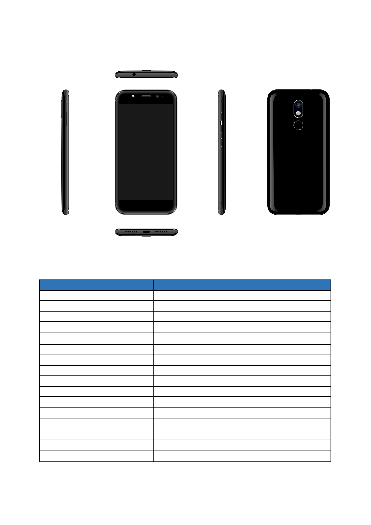
E460 L2 Service Manual
Particular
Remarks
Key Matrix For Flashing
NA
Chipset
Qualcomm 8940
Android Version
Android M
Frequency
1.4G OCTA
Network Mode
850MHz/900MHz/1800MHz/1900MHz
WCDMA Band
B1/B2/B5/B8
4G Band
B1/B3/B7/B8/B20/B40/B38/41/B28A/B5
Rom
16G
RAM
3G
Internal SD Card memory
8.79G
Expandable Memory
128G
Factory mode code
Press Volume- & power key at the same time
Good Earpiece volume
32Ω± 15%
Good Loudspeaker volume
8Ω± 5%
Good MIC volume
2.2kΩ± 5%
Good Vibrator volume
30Ω± 5%
1: Technical Specifications
Page 2
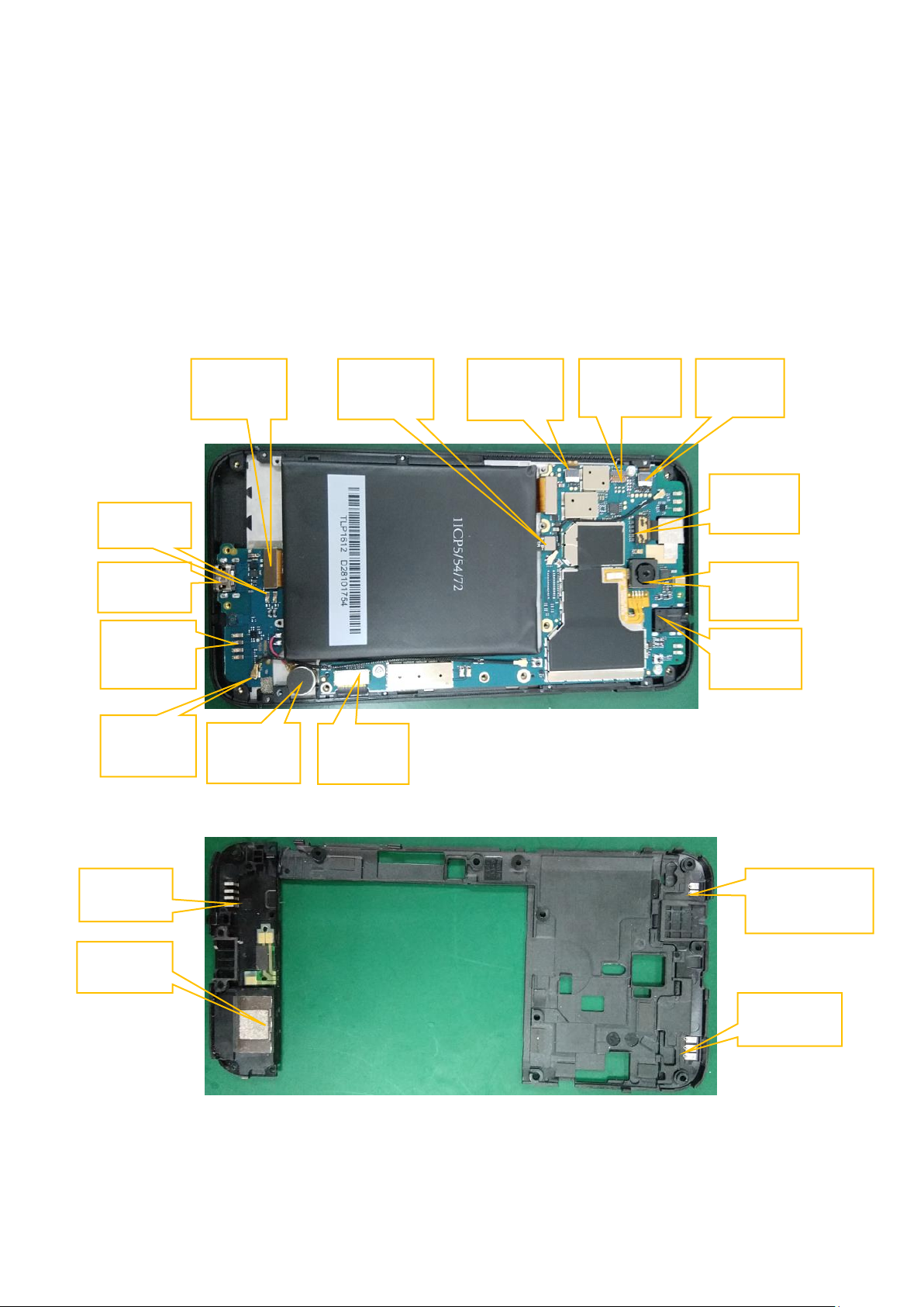
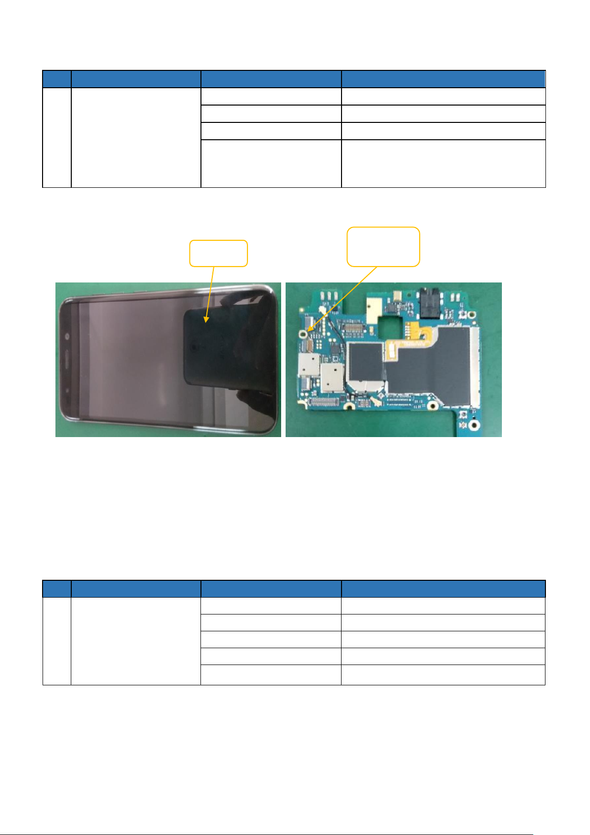
Main
Camera
LCD&TP
connector
SPK box
TP
connector
Front
camera
Battery
connector
RF cable
Vibrator
I/O
SPK slot
RF ANT
WIFI/GPS/BT
Antenna
Earphone
Connector
Key FPC
Connector
Main FPC
RF ANT
Slot
RF ANT
Fingerprint
Connector
2: CAUTIONS
I. Upgrading & Servicing must be undertaken by qualified personnel only.
II. Ensure all work is carried out at an anti-static workstation and that an anti-static wrist strap is worn.
III. Use only approved Tools & components as specified in the parts list.
IV. Ensure all components, modules, screws, and insulators are correctly re-fitted after servicing and
alignment
V. Ensure all cables and wires are repositioned correctly if Handset disassembled
VI. Electrostatic discharge can easily damage the sensitive components of electronic products. Therefore,
Service Centre must adhere the precautions which mentioned above.
3: service Details
Page 3
1. Does not power on
SN.
Possible Cause
Validation steps
Action
1
Battery
a) Check battery PIN if it is damage or
oxidation
b) Check voltage with Multi meter Value
must be 3.7V DC or above
a) Clean battery PIN
b) Charge the battery or
replace for a new
battery
2
Power Key
Power key FPC fail
a) Clean power key FPC
b) Replace for a new FPC
3
SW failure
Upgrading with latest software
Upgrading
4
Battery
Connector
Check battery connector if it is broken or
oxidation
Clean the battery
connector or change for a
new one.
5
PCB
Check shorting with Multi meter
Suspected PCB faulty
Change PCBA
Power- Key
Battery
connector
Page 4
2. Display issue/No display
SN.
Possible Cause
Validation steps
Action
1
No display
SW issue
Flash the handset with latest SW
LCD issue
Clean LCD connector/Re-assemble
LCD/Replace it
LCD issue
Re solder LCD connector/ change a new
LCD (NA)
PCBA issue
Clean LCD connector)/Re-assemble to
PCBA
2
Colored screen
LCD issue
Re-assemble LCD/Replace it
3
Dark screen
LCD issue
Re-assemble LCD/Replace it
LCD backlight circuit issue
Change PCBA
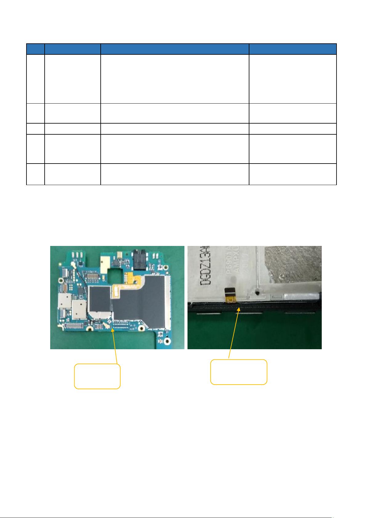
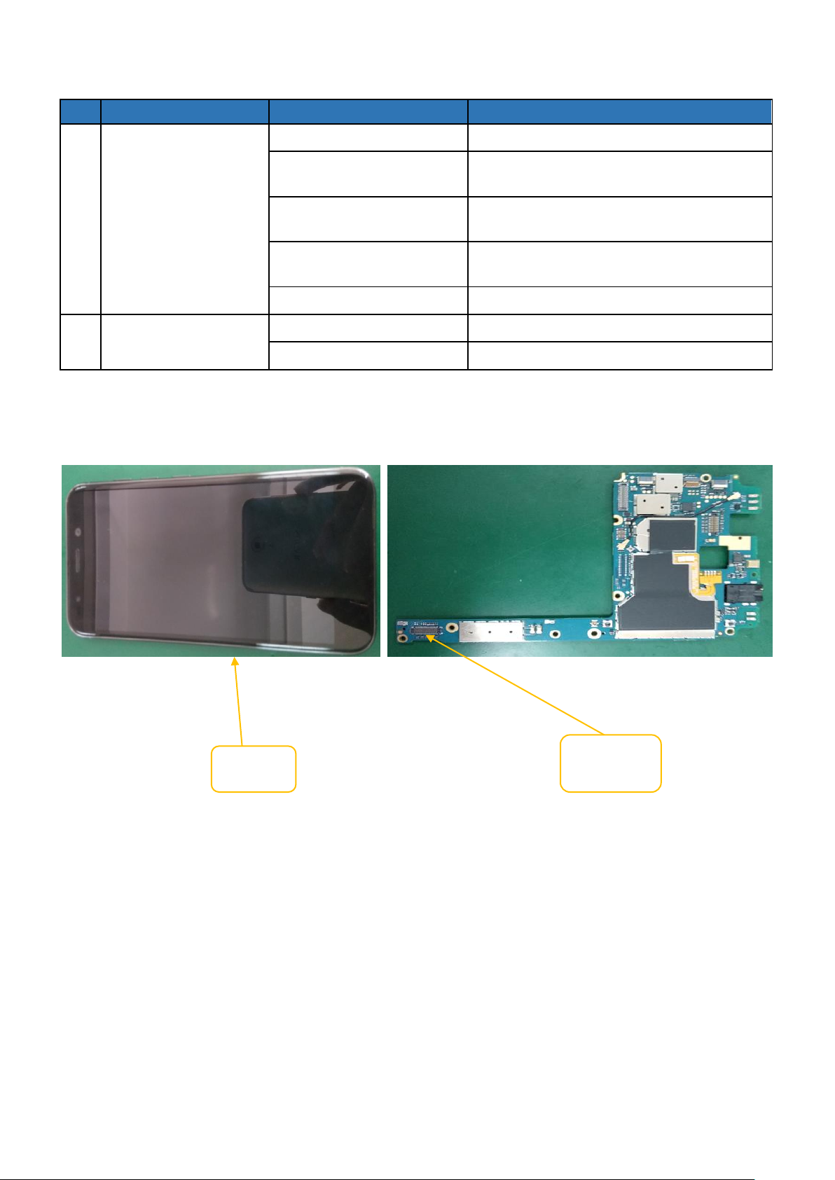
LCD
connector
LCD/TP
Page 5
3. Touch panel
SN.
Possible Cause
Validation steps
Action
1
TP not working
SW Issue
Flash the handset with latest SW
TP issue
Clean TP connector/Re-assemble TP
TP issue
Re-solder TP FPC/ change TP(NA)
PCBA issue
a) Clean TP connector/ Re-assemble
TP
b) Change PCBA
SN.
Possible Cause
Validation steps
Action
1
Finger print Failure
SW Issue
Flash the handset with latest SW
Finger print Failure
Re-assemble / Change Finger print
SUB PCBA Failure
Re-assemble / Change SUB PCBA
Main FPC Failure
Re-assemble / Change Main FPC
PCBA issue
Re-assemble / Change PCBA
TP/LCD
TP
connector
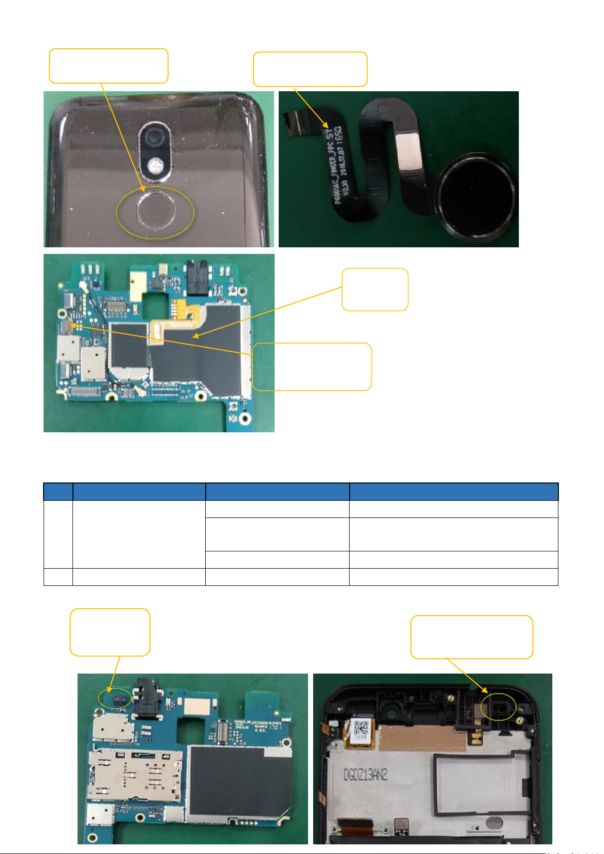
4. Fingerprint
Page 6
SN.
Possible Cause
Validation steps
Action
1
Proximity sensor fail
SW Issue
Flash the handset with latest SW
Sensor holder is not
assembled well
Clean it and Re-assemble the sensor
holder
PCBA issue
Change PCBA
2
Front housing assay fail
Front housing issue
Change for a new front housing assay
Proximity
sensor
P-Sensor silicone gel
sleeve
Fingerprint module
Fingerprint module
PCBA
Fingerprint module
connector
5. Proximity Sensor
Page 7

SN.
Possible Cause
Validation steps
Action
1
Gyroscope fail
SW Issue
Flash the handset with latest SW
PCBA issue
Change PCBA
SN.
Possible Cause
Validation steps
Action
1
Hall fail
SW Issue
Flash the handset with latest SW
PCBA issue
Change PCBA
Gyroscope
sensor
HALL
6. Gyroscope sensor
7. Hall
Page 8

SN.
Possible Cause
Validation steps
Action
1
Key is not response
Key is fail
Change Key
Re-solder Key FPC(NA)
2
The feeling of pressing
key is bad
Key is fail
Change Key
Some dust with dome
Clean it
Key is not assembled well
Re-assemble it
Power -Key
Power- Key
Connector
8. Keys
Page 9

9. Charging
SN.
Possible Cause
Validation steps
Action
1
Cannot charge
Adapter is fail
Change adapter
Cable is fail
Change Cable
Battery is issue
Charging / Change it
Main FPC issue
Re-assembly or Change it
SUB PCBA issue
Change SUB PCBA
USB socket
Clean the socket
2
Have charging icon, but
not charged
SW Issue
Flash the handset with latest SW
Battery connector issue
Change PCBA
Battery fail
Change battery
PCBA fail
Change PCBA
Main FPC
Battery
connector
Adapter
SUB
PCBA
USB
Cable
Page 10

10. Cannot connect to PC
SN.
Possible Cause
Validation steps
Action
1
Cannot connect to PC
USB cable is fail
Change USB cable
SUB PCBA fail
Change SUB PCBA
Main FPC issue
Re-assembly or Change it
Systems driver issue
Update systems driver.
PCBA fail
Change PCBA
USB
Cable
I/O
connect
Main
FPC
Page 11

11. Front Camera
SN.
Possible Cause
Validation steps
Action
1
Colored screen when
open front camera
Camera is issue
Re-assembly camera or Change it
PCBA fail
Clean camera connector
PCBA fail
Re-solder camera(NA)
PCBA fail
Change PCBA
2
Cannot turn on front
camera
SW issue
Flash the handset with latest SW
Camera issue
Clean camera connector/Re-assembly
Camera issue
Re-assemble camera/Change Camera
PCBA fail
Change PCBA
Front camera
connector
Front
camera
Page 12

12. Rear Camera
SN.
Possible Cause
Validation steps
Action
1
Colored screen when
open Rear camera
Camera is issue
Re-assembly camera or Change it
PCBA fail
Clean camera connector
PCBA fail
Re-solder camera(NA)
PCBA fail
Change PCBA
2
Cannot turn on Rear
camera
SW issue
Flash the handset with latest SW
Camera issue
Clean camera connector/Re-assembly
Camera issue
Re-assemble camera /Change Camera
PCBA fail
Change PCBA
SN.
Possible Cause
Validation steps
Action
1
WI-FI/BT not working
Set turn off as default
Reset to turn on Wi-Fi
SW issue
Flash the handset with latest SW
Wi-Fi/BT antenna
Re-assemble rear housing or change
rear housing
PCBA issue
Clean PCBA Antenna Slot
PCBA issue
Change PCBA
Rear camera
connector
Rear camera
13. Wi-Fi/BT
Page 13

SN.
Possible Cause
Validation steps
Action
1
GPS not working
Set turn off as default
Reset to turn on wifi
SW issue
Flash the handset with latest SW
GPS antenna
Re-assemble rear housing or change
rear housing
PCBA issue
Clean PCBA Antenna Slot
PCBA issue
Change PCBA
Wi-Fi/BT
antenna
Antenna
Slot
GPS antenna
Antenna
Slot
14. GPS
Page 14

SN.
Possible Cause
Validation steps
Action
1
SIM not working
Set turn off as default
Reset to turn on SIM
SW issue
Flash the handset with latest SW
SIM slot issue
Clean sim slot or adjust the pin
SIM card issue
Change sim card
PCBA issue
Change PCBA
SIM Socket
15. SIM
Page 15

16. RF Network
SN.
Possible Cause
Validation steps
Action
1
RF Network cannot
searchable
SW issue
Flash the handset with latest SW
RF parameter issue
Back up and copy RF parameter
RF antenna issue(rear
housing)
Re-assemble or Change rear housing
RF antenna issue(SUB
PCBA)
change SUB PCBA
Some dust with RF Slot
Clean it
RF Coaxial line issue
Re-assemble or Change it
RF connector issue(PCBA)
Clean/ re-assemble
PCBA fail
Change PCBA
RF antenna
Slot
RF Coaxial
line
RF
antenna
RF
connector
RF antenna
Slot
Page 16

17. Receiver
SN.
Possible Cause
Validation steps
Action
1
Noise/crack
Dust with receiver
Change receiver
Receiver issue
a) Re-assemble or Change it
b) Change receiver dust proof net
2
No sound/volume low
Receiver is set too low by
person
Reset the value of volume
PCBA issue
Clean PCBA solder pad/ change receiver
PCBA issue
Change PCBA
SN.
Possible Cause
Validation steps
Action
1
Vibrating is not properly
Vibrator assemble issue
Re assemble it
SW issue
Flash the handset with latest SW
Main FPC issue
Re-assembly Main FPC or change it.
2
NO vibrate
Soldering issue
Re soldering it
Vibrator issue
Change Vibrate
Soldering issue(SMT)
Change SUB PCBA(NA)
Vibrator SUB issue
Re-assembly Vibrate SUB PCBA
PCBA issue
Clean Main FPC connector/
Re-assemble PCBA
3
Vibrate weakly
Vibrator issue
Change it
Receiver
Receiver
slot
18. Vibrator
Page 17

SN.
Possible Cause
Validation steps
Action
1
Not working / from
earphone
SW issue
Flash the handset with latest SW
Earphone is fail
Change Earphone
earphone connector
issue
Clean earphone connector/ re-connect
PCBA fail
Change PCBA
Earphone
Earphone
connector
Main FPC
Main FPC
connector
Vibrator
Connector
SUB
PCBA
Vibrator
19. Earphone
Page 18

SN.
Possible Cause
Validation steps
Action
1
Noise with uplink side
Some dust with MIC
Remove the dust/ Re-assemble MIC
holder
MIC issue
Change SUB PCBA
Re-assemble or Change Main FPC
Clean Main FPC connector/
reassemble
PCBA issue
Change PCBA
2
Volume low
MIC dust-proof net issue
Clean dust-proof net/ Change it
Volume is set too low by person
Reset the value of volume
SW issue
Flash the handset with latest SW
PCBA issue
Change PCBA
No recording
SW issue
Flash the handset with latest SW
MIC issue
Re-assemble SUB PCBA/ Change it
PCBA issue
Change PCBA
MIC 2
MIC
Main FPC
connector
Main FPC
20. MIC
Page 19

21. Speaker
SN.
Possible Cause
Validation steps
Action
1
Noise/crack
Speaker with dust
Clean speaker
Speaker foam issue
Change Speaker foam
Speaker issue
Re-assemble/ Change speaker
2
No volume
Assemble issue
Assemble again
SW issue
Flash the handset with latest SW
SUB PCBA issue
Re-assemble or change SUB PCBA
Main FPC issue
Re-assemble Main FPC or change it
PCBA issue
Clean Main FPC connector/ change
PCBA
3
Low volume
Assemble issue
Assemble again
Volume is set too low by
person
Reset the value of volume
Speaker issue
Change it
Audio PA issue
Change PCBA
SN.
Possible Cause
Validation steps
Action
1
Battery bulge
Battery issue
Change battery
2
No battery
Battery PIN issue
Clean battery PIN
Battery issue
Change battery
Speaker
BOX
SPK Slot
Main FPC
connector
Main
22. Battery
Page 20

3
Low Battery
Battery issue
Charge/ change it
PCBA issue
Clean battery connector/
re-assemble it
PCBA issue
Change PCBA
Battery
Battery
connector
Thanks
 Loading...