

Micromax Q427+ Service Manual
Q427+ L2 Service Manual
Particular
Remarks
Key Matrix For Flashing
NA
Chipset
MT6735P
Android Version
Android 6.0
Frequency
1.3GHz
Network Mode
2G: 850MHz/900MHz/1800MHz/1900MHz
3G: B1 B8
Data Segment
GPRS, EDGE, HSPA+ 21Mbps, FDD-LTE, TDD-LTE
Rom
16G
RAM
2G
Internal SD Card memory
12G
Expandable Memory
64G
Factory mode code
Press vol+/ Vol-/ power key at the same time
Good Earpiece volume
32Ω± 15%
Good Loudspeaker volume
8Ω± 5%
Good Mic volume
2.2kΩ± 5%
Good Vibrator volume
30Ω± 5%
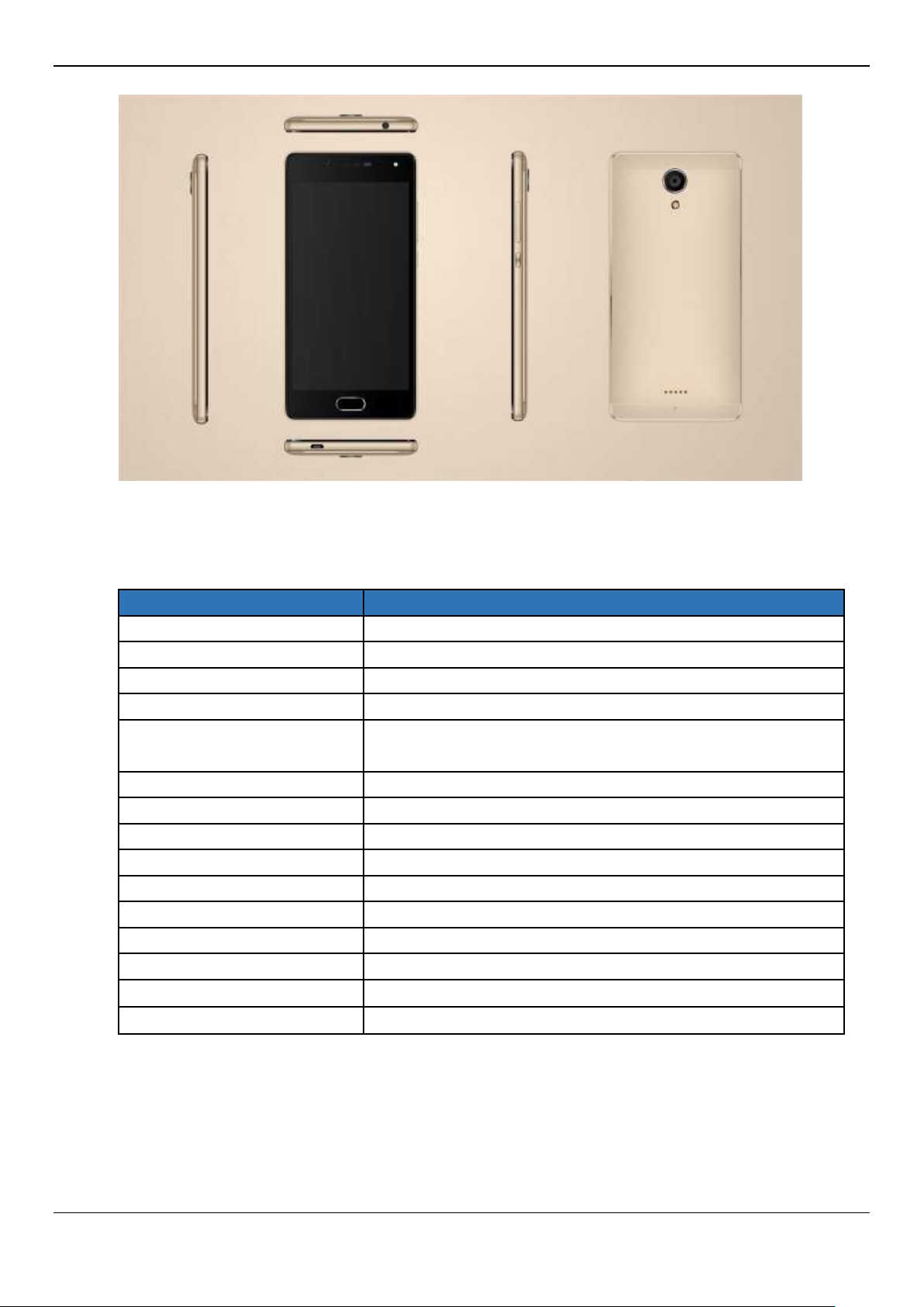
1:Technical Specifications
Q427+ L2 Service Manual
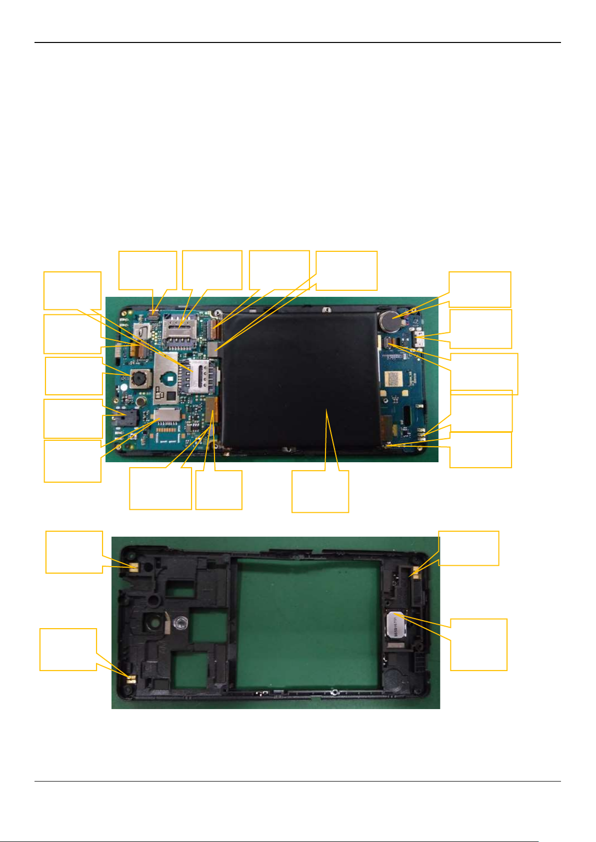
Main
camera
Earphone
connector
Vibrator
Charge
connector
Front
camera
SIM
connector
TP
Connetor
SIM
connector
Battery
connector
RF coaxial
line
RF
Antenna
Main
FPC
LCD
connector
GPS
ANT
SPK
RF ANT
T-Flash
connecto
Volume
key FPC
Battery
Wifi /BT
ANT
Fingerprint
FPC
2:CAUTIONS
I. Flashing & Servicing must be undertaken by qualified personnel only.
II. Ensure all work is carried out at an anti-static workstation and that an anti-static wrist strap is worn.
III. Use only approved Tools & components as specified in the parts list.
IV. Ensure all components, modules, screws, and insulators are correctly re-fitted after servicing and
alignment
V. Ensure all cables and wires are repositioned correctly if Handset disassembled
VI. Electrostatic discharge can easily damage the sensitive components of electronic products.
Therefore, Service Centre must adhere the precautions which mentioned above.
3、service Details
Q427+ L2 Service Manual
S.NO
Possible Cause
Validation steps
Action
1
Shorting
Check shorting with Multi meter
Replace PCB if found
faulty
2
Battery
a) Clean the 3 or 4 golden color
point(its terminals)on the battery
b) Check voltage with Multi meter
Value must be 3.7V DC or above
Replace if found faulty
3
Battery
Connector
a) Check battery connector
b) Keep Multi meter on 20V DC and
check value must be 1.5 to 3.5V DC
Re-solder/Replace if
found faulty
4
SW failure
Flashing with latest software
Flashing
5
Power on Key
Key failure
Re-solder/Replace if
found faulty
6
PCB
Suspected PCB faulty
Refer L3 repair
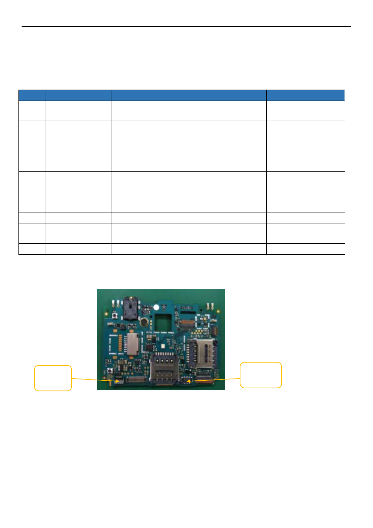
Side Key
Battery
connector
1. Does not power on
Q427+ L2 Service Manual
S.NO
Possible Cause
Validation steps
Action
1
No display
SW issue
Flash the handset with latest SW
LCD issue
Re-assembly LCD/Replace it
PCBA issue
Re-assembly PCBA/Replace it
PCBA issue
Re-Solder the LCD connector or change it
2
Colored screen
LCD issue
Re-assembly LCD/Replace it
3
Dark screen
LCD issue
Re-assembly LCD/Replace it
SW issue
Flash the handset with latest SW
LCD backlight circuit issue
Refer L3 repair
LCD backlight is set
too low by person
Reset the value of backlight
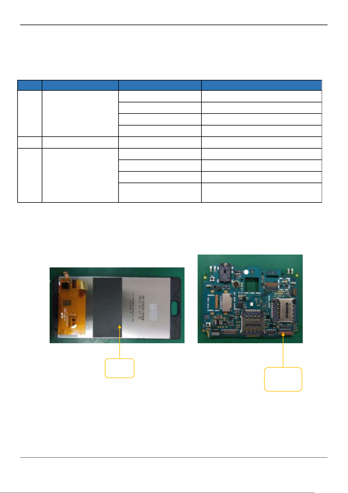
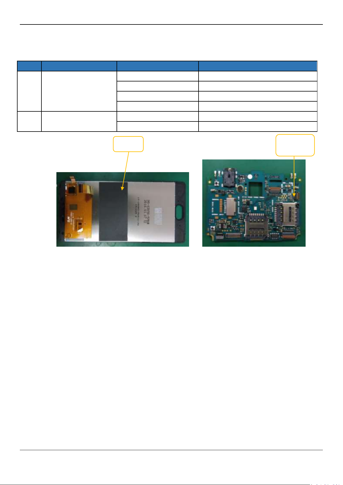
LCD
connector
LCD
2:Display issue/No display
Q427+ L2 Service Manual
S.NO
Possible Cause
Validation steps
Action
1
TP not working
SW Issue
Flash the handset with latest SW
TP issue
Re-assembly TP/Replace it
PCBA issue
Refer to L3 repair
PCBA issue
Re-Solder the TP connector or change it
2
TP not working proper
TP issue
Re-assembly TP/Replace it
PCBA issue
Refer to L3 repair
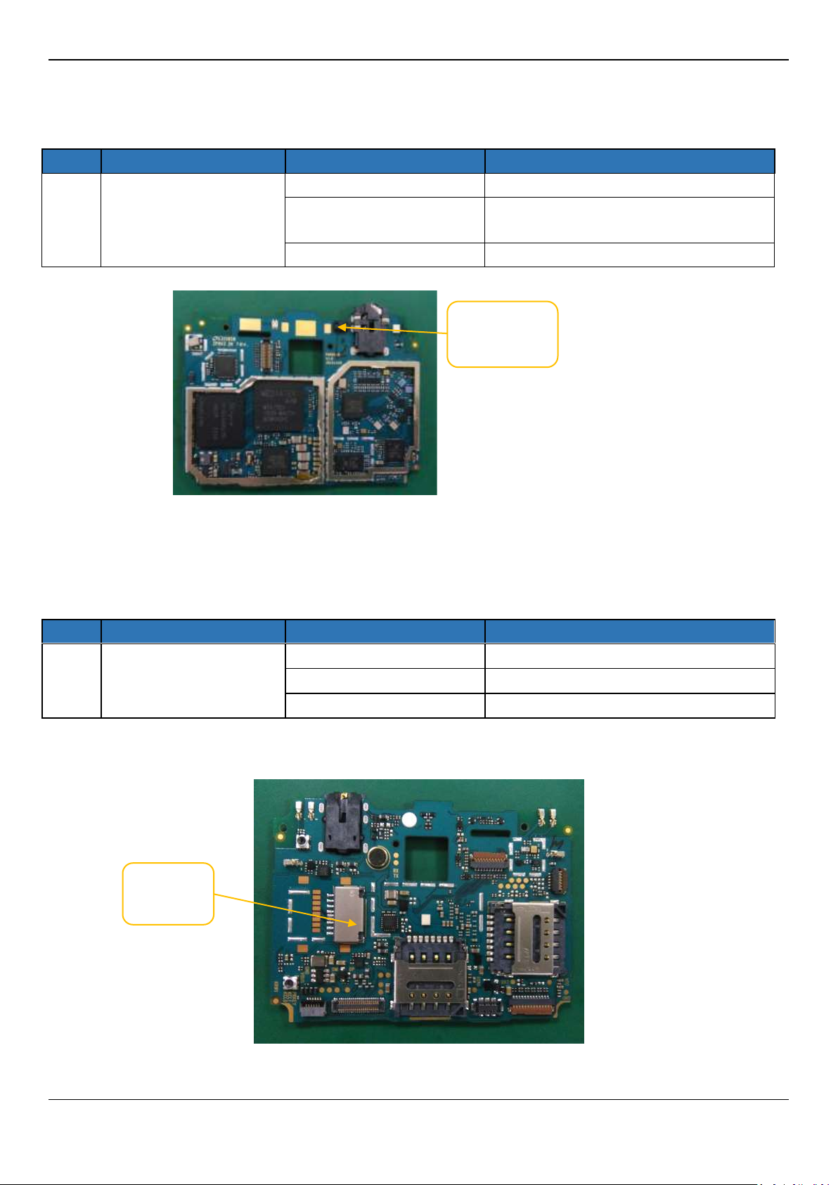
TP
TP
3:Touch panel
Q427+ L2 Service Manual
S.NO
Possible Cause
Validation steps
Action
1
Proximity sensor fail
SW Issue
Flash the handset with latest SW
Sensor holder is not
assembled well
Re-assemble the sensor holder
PCBA issue
Change PCBA
S.NO
Possible Cause
Validation steps
Action
1
G-sensor is not working
SW Issue
Flash the handset with latest SW
Set problem
Reset mobile
PCBA issue
Change PCBA
Proximity
sensor
G-sensor
4:Proximity Sensor
5:G-sensor
 Loading...