

Page 1

WWW.MICRO-MATIC.NO
© 2016 OJ Electronics A/S
MTC3-1991
User Manual
67564 05/16 (JRK)
Page 2

PAGE 2
© 2016 OJ Electronics A/S
Contents
Contents . . . . . . . . . . . . . . . . . . . . . . . . . . . . . . . . . . . . 2
Introduction . . . . . . . . . . . . . . . . . . . . . . . . . . . . . . . . . . 3
Menu Overview . . . . . . . . . . . . . . . . . . . . . . . . . . . . . . . . 4
APP : Sensor Application 1/2 . . . . . . . . . . . . . . . . . . . . . . . 5
APP : Sensor Application 2/2 . . . . . . . . . . . . . . . . . . . . . . . 6
SCA : Temperature Scale. . . . . . . . . . . . . . . . . . . . . . . . . . 7
Li : Floor Temperature Limit . . . . . . . . . . . . . . . . . . . . . . . . 8
TP : Temperature Readout . . . . . . . . . . . . . . . . . . . . . . . . . 9
LCD : Display Settings . . . . . . . . . . . . . . . . . . . . . . . . . . 10
ADJ : Adjust . . . . . . . . . . . . . . . . . . . . . . . . . . . . . . . . . 11
NSB : Night Setback. . . . . . . . . . . . . . . . . . . . . . . . . . . . 12
DEF : Frost Protection. . . . . . . . . . . . . . . . . . . . . . . . . . . 13
PWM : Pulse Width Modulation. . . . . . . . . . . . . . . . . . . . . 14
PLI : Power Limit 1/2 . . . . . . . . . . . . . . . . . . . . . . . . . . . 15
PLI : Power Limit 2/2 . . . . . . . . . . . . . . . . . . . . . . . . . . . 16
TIME : Time and Event Setting 1/2. . . . . . . . . . . . . . . . . . . 17
TIME : Time and Event Setting 2/2. . . . . . . . . . . . . . . . . . . 18
SW : Software Version . . . . . . . . . . . . . . . . . . . . . . . . . . 19
Done : Exiting the Menu . . . . . . . . . . . . . . . . . . . . . . . . . 20
Troubleshooting and Additional Information . . . . . . . . . . . . 21
Changing the Front Cover . . . . . . . . . . . . . . . . . . . . . . . . 22
Contact : Help and Support . . . . . . . . . . . . . . . . . . . . . . . 23
Page 3

PAGE 3
© 2016 OJ Electronics A/S
Introduction
Thank you for buying our MTC3 thermostat.
We hope you will enjoy the ease of use oered by the
well-known user interface and design.
This high-quality thermostat is designed to have a
minimum of impact on the environment and will at the
same time provide you with long-lasting heating comfort.
The thermostat will switch on your heating system at
predetermined times each day of the week.
The thermostat is preset with up to four events for each
day of the week. Lowering the temperature when your
home is unoccupied will reduce your energy costs without
reducing comfort.
The thermostat comes with preset heating schedules
suitable for most homes.
MTC3 has a temperature setting range of 0-40°C, a night
setback, frost protection and limit temperatures to ensure
your comfort and protect your property from excessive
temperatures.
The front cover can be flipped down.
Behind the front cover, on the left side of the front, there
is an on/o switch, up = on / down = o.
On the right side, there are three buttons.
An upper button, a centre button and a lower button.
The centre button is used to access the menu and
confirm changes and settings made in the menu.
The upper and lower buttons are used to navigate through
the menu and change parameters and settings.
To access the menu, activate the thermostat by pushing
any of the three buttons.
Then hold the centre button in for five seconds.
Note: If you hold the centre button for ten seconds, the
thermostat will perform a factory reset, i.e. all settings will
then be reset to their factory settings.
This thermostat can be used as a controller for electric
room heating pursuant to EN50559.
Page 4

PAGE 4
© 2016 OJ Electronics A/S
Menu Overview
Menu Setting Options Factory Setting
APP APP: A; F; C; AF; AE A
SCA
SChi: SCLo - 40.0°C
SCLo: 0.0°C - SChi
40°C
0°C
Li
Lihi: LiLo - 40°C
LiLo: 0°C - Lihi
28°C
15°C
tP
FLo: Actual measured temperature
ro: Actual measured temperature
Readout
Readout
LCd
SCA: C; nu
diS: SP; tP
C
SP
AdJ Measured temperature +/- 10°C 0.0°C
nSb 2.0°C - 8.0°C 5.0°C
dEF 5.0° - 10.0°C 8.0°C
Menu Setting Options Factory Setting
PWM
oFF; on; AUt Aut
oFF diF: 0.3-10.0 0.4
AUt
CYHi: 10-60
CYLo: 10-30
30
15
Pli 0-30 min 0 min
TiMe
ModE: oFF; 5:2; 6:1; 7:0; 0:7
dAY: Non; tuE; UEd; thu; Fri; SAt; Sun
hour: 0-23
min: 0-59
oFF
None
None
None
SW None Readout
Done Save settings and exit the menu None
Page 5
PAGE 5
© 2016 OJ Electronics A/S
This option allows you to choose which sensor is used to
control the heating system. If a factory reset is performed,
the thermostat will autodetect an external sensor.
• A: With this setting, the internal room sensor inside
the thermostat controls the heating system.
• F: With this setting, the floor sensor controls the heating system.
• C: With this setting, the thermostat operates as a
regulator and no sensors are used. The setting is a
percentage of the full load in increments of 1%.
Note that Floor Protection is not active when using
the thermostat as a regulator.
• AF: With this setting, the internal room sensor controls
the heating system subject to maximum and minimum limits for floor temperature.
The maximum temperature limit protects wooden
floors from excessive heat.
The minimum temperature limit prevents the floor
from becoming uncomfortably cold when heating is
not needed, e.g. in a bathroom. Note that this function will increase energy consumption. Floor Limit
temperatures are set in the “Li : Floor Temperature
Limit” menu.
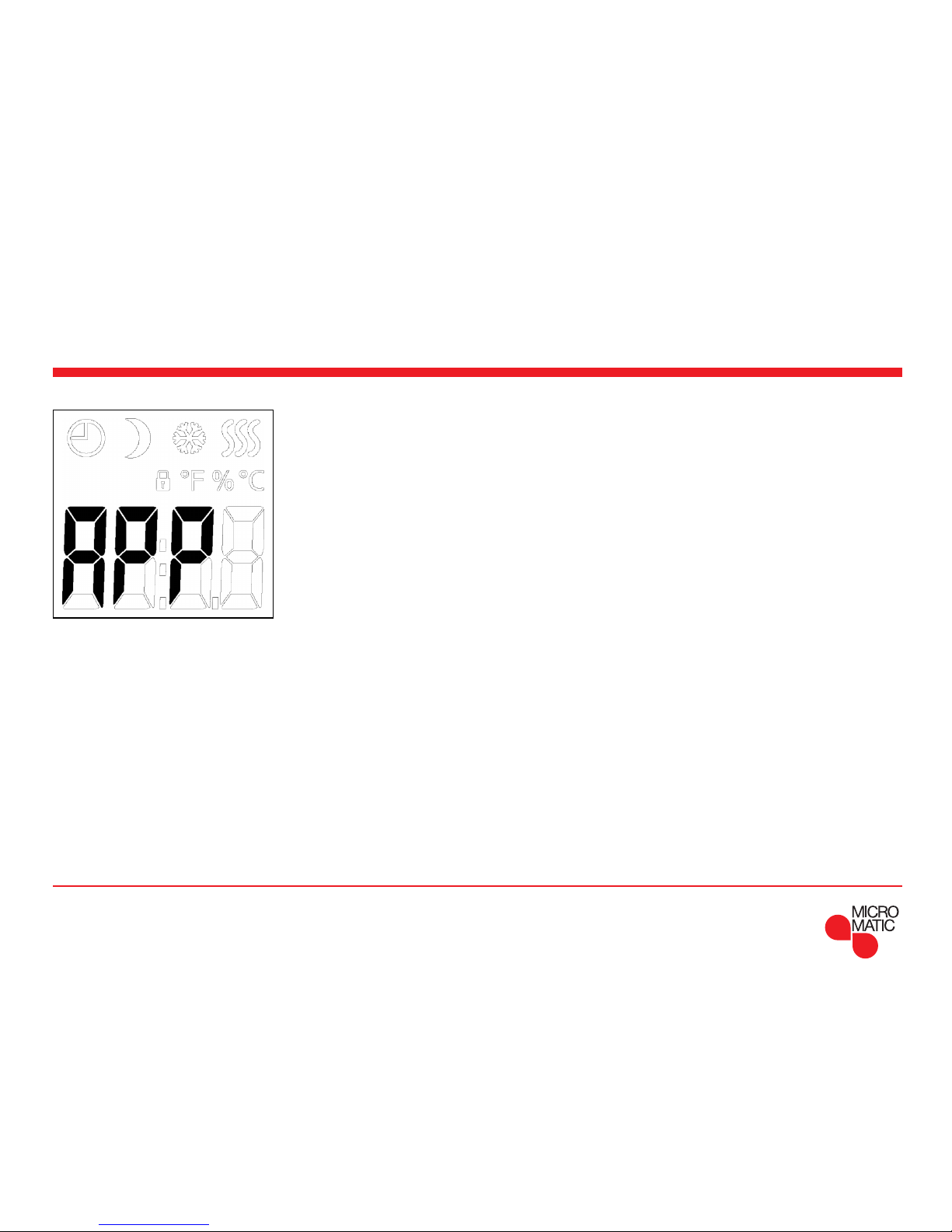
APP : Sensor Application 1/2
Page 6

PAGE 6
© 2016 OJ Electronics A/S
Menu structure:
APP: A; F; C; AF; AE Factory: A
How to execute it:
• Access the menu.
• Scroll through the menu to APP.
• Press the centre button to enter the SENSOR
APPLICATION setting.
• Use the upper or lower button to select the application
that suits your installation.
• Confirm your choice with the centre button.
APP: Sensor Application 2/2
• AE: With this setting, an optional external room sensor
(connected to the floor sensor terminals) controls
the heating system.
Page 7
PAGE 7
© 2016 OJ Electronics A/S
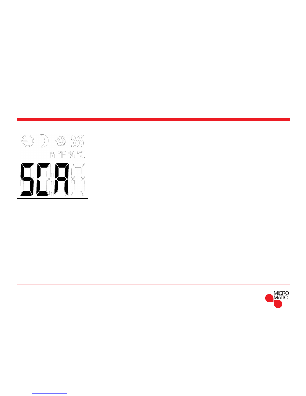
SCA : Temperature Scale
This option allows you to set the minimum and maximum
temperatures to which the thermostat can be set.
Operating temperatures:
• SChi: Maximum Temperature Scale can be set to
between the Minimum Temperature and 40°C.
• SCLo: Minimum Temperature Scale can be set to
between 0°C and the Maximum Temperature.
(If “Sensor Application” is set to “Floor”, a maximum
temperature of 27°C can protect wooden floors from
drying out. For precise information, please ask your flooring supplier).
How to execute it:
• Access the menu.
• Scroll through the menu to SCA.
• Press the centre button to enter the Scale settings.
• Use the upper or lower button to set the limit for the
highest temperature the thermostat may use as a setpoint temperature.
• Confirm your choice with the centre button.
• Use the upper or lower button to set the limit for the
lowest temperature the thermostat may use as a setpoint temperature.
• Confirm your choice with the centre button.
Menu structure:
SCA:
SChi: 0.0°C - 40.0°C Factory: 40.0
SCLo: 0.0°C - SChi Factory: 00.0
Page 8

PAGE 8
© 2016 OJ Electronics A/S
Li : Floor Temperature Limit
This option allows you to set the minimum and maximum
limits for floor temperature.
Floor limit temperatures:
Floor limit temperatures allow you to set the highest (Lihi)
and lowest (LiLo) permissible floor temperature during
room temperature control with the sensor application AF.
If floor temperature rises above the maximum temperature
limit, the thermostat will deactivate the heating system to
maintain the temperature below the set maximum.
If floor temperature drops below the minimum temperature limit, the thermostat will activate the heating system to
maintain the temperature above the set minimum.
Note that this feature is only applicable in the sensor
application AF.
How to execute it:
• Access the menu.
• Scroll through the menu to Li.
• Press the centre button to enter the Limit setting.
• Use the upper or lower button to set the limit for the
highest temperature the thermostat may reach.
• Confirm your choice with the centre button.
• Use the upper or lower button to set the limit for the
lowest temperature the thermostat may reach.
• Confirm your choice with the centre button.
Menu structure:
Li:
Lihi: LiLo - 40°C Factory: 28°C
LiLo: 0°C - Lihi Factory: 15°C
Page 9

PAGE 9
© 2016 OJ Electronics A/S
TP : Temperature Readout
Depends on which sensors are connected and which
sensor application is chosen. Temperatures from the floor
sensor and the internal room sensor can be monitored
here.
Display settings are not applicable if the sensor application is set to C.
How to execute it:
• Access the menu.
• Scroll through the menu to TP.
• Press the centre button to enter the temperature
readout.
Either the floor sensor temperature, the room sensor
temperature or both are shown depending on the sensor
application setting.
• Use the centre button to jump to the next sensor type
and jump to the menu.
Menu structure:
TP:
FLo: Actual measured floor temperature
ro: Actual measured room temperature
Page 10

PAGE 10
© 2016 OJ Electronics A/S
LCD : Display Settings
This option allows you to select what data you want to be
shown in the idle display.
SCA = Temperature scale setting:
C = Celsius
(nU = numerical 0-100%)
DiS = Displayed in idle display:
SP = Setpoint temperature
tP = Measured temperature
Display settings are not applicable if the sensor application is set to C.
How to execute it:
• Access the menu.
• Scroll through the menu to LCD.
• Press the centre button to enter the temperature scale
setting.
• Use the upper or lower button to toggle between the
dierent options.
• Confirm your choice with the centre button.
• Use the upper or lower button to toggle between the
dierent options.
• Confirm your choice with the centre button.
Menu structure:
LCd
SCA: C; nu Factory: C
diS: SP; tP Factory: SP
Page 11

PAGE 11
© 2016 OJ Electronics A/S
ADJ : Adjust
This option allows you to calibrate the measured room
temperature.
You should calibrate the sensor if the temperature reading
diers from the actual temperature.
The measured temperature has to be entered.
Note that with sensor application F, the temperature is
measured in the floor, this temperature would be higher
than the ambient temperature.
Adjust is not applicable if the sensor application is set
to C.
How to execute it:
You can calibrate the sensor with +/- 10°C in steps of
0.1°C as follows:
• Access the menu.
• Scroll through the menu to ADJ.
• Press the centre button.
• Use the upper or lower button to adjust the sensor to
the value by which you want to increase/decrease the
temperature.
• Confirm your choice with the centre button.
Menu structure:
AdJ:
Measured temperature +/- 10°C Factory: 0.0°C
Page 12

PAGE 12
© 2016 OJ Electronics A/S
NSB : Night Setback
This option allows you to set the value by which the temperature should be reduced when NSB is activated. NSB
is activated either by the event schedule or with a signal
from an external timer connected to terminal S.
When the NSB signal is active, a half-moon icon is shown
in the display together with the lowered setpoint
temperature.
The function is factory set to 5°C but can be set to values
between 2-8° in increments of 0.5°C.
If the Application is set to C and ”Night setback” is
selected, the night setback is set in relative values. The
setpoint specifies (in percent) the time that the unit is to
remain active in a PWM cycle, which is usually 20 min.
Setback degree is specified as a percentage of the
setpoint. The setpoint multiplied by the setback degree
gives the activation degree.
Example: If the setpoint is set to 60% and night setback
is set to 25%, the activation degree will be (0.60 x 0.25 =
0.15) = 15%.
How to execute it:
• Access the menu.
• Scroll through the menu to NSB.
• Press the centre button to enter the Night setback
setting.
• Use the upper or lower button to adjust the value by
which you want to decrease the temperature when NSB
is activated.
• Confirm your choice with the centre button.
Menu structure:
nSb:
2.0 - 8.0 Factory: 5.0°C
Page 13

PAGE 13
© 2016 OJ Electronics A/S
DEF : Frost Protection
This option allows you to set the parameters for any possible frost protection function.
An external signal can activate the frost protection, the
thermostat will then maintain a fixed floor/room temperature.
The function is factory-set to 8°C but can be set to values
from 5-10° in increments of 0.5°C.
If the Application is set to C and ”Frost protection” is
selected, then frost protection is set in absolute values in
percent.
How to execute it:
• Access the menu.
• Scroll through the menu to DEF.
• Press the centre button to enter the frost protection
settings.
• Use the upper or lower button to set the temperature
you want to be the setpoint temperature when DEF is
activated.
• Confirm your choice with the centre button.
Menu structure:
dEF: 5.0° - 10.0°C Factory: 8.0°C
Page 14

PAGE 14
© 2016 OJ Electronics A/S
PWM : Pulse Width Modulation
With this setting, you can change the duration of the
heating periods.
O: Simple “on/o” regulation, where the relay is closed
when the measured temperature is below the setpoint,
and opened when the measured temperature is above
the setpoint. Hysteresis (diF) is used to avoid too frequent
relay switching.
Auto: Like “PWM On”, but the PWM period is increased
or decreased depending on the minimum and maximum
temperature measured during a PWM period. This will
increase the lifetime of the relay by reducing the number
of relay switches, but still ensure the comfort of the user
by keeping the temperature swings below an acceptable
level.
How to execute it:
• Access the menu.
• Scroll through the menu to PUn.
• Press the centre button to enter the PWM settings.
• Use the upper and lower button to toggle between the
dierent Pulse width modulation modes.
• Confirm your choice with the centre button.
• Use the upper or lower button to set the hysteresis or
duty cycle.
• Confirm your choice with the centre button.
Menu structure:
PWM: oFF; on; AUt
oFF: diF: 0.3-10.0 Factory: 0.4
AUt: CYHi: 10-60 Factory: 30
CYLo: 10-30 Factory: 15
Page 15

PAGE 15
© 2016 OJ Electronics A/S
PLI : Power Limit 1/2
This thermostat complies with EN 50559 (VDE 0705-559) for
electrical floor heating. The regulation applies to electrical
floor heating with a maximum floor weight of 4 kN/m². To
ensure that hotspots due to unintentionally covering up
part of the surface are avoided, the heating function can be
time-limited as per EN/DIN.
Note that this function is not applicable to other heating
applications such as wall and/or ceiling heating. If it can be
foreseen in advance that unintentional covering up of part
of a floor might occur, then it is important to assess the
correct period of time for which the floor heating must be
time-limited.
The heating can be limited by using a set number of
minutes per hour. The thermostat will then divide the given
number of minutes per hour up into 3 periods, depending
on the thermostat’s actual PWM cycle.
Example:
If obstacles could be present that cover up a part of the
floor, then the heating might need to be limited by some
number of minutes so as to avoid hotspots in the floor.
If you want the thermostat to heat a maximum of 90% of
the time, then the thermostat should be limited by 10%.
Ten percent of one hour is 6 minutes. Enter 6 min. in the PLI
menu in order to lower the heating by 10%.
Page 16

PAGE 16
© 2016 OJ Electronics A/S
PLI : Power Limit 2/2
Equation to calculate number of minutes that could be
entered in the PLI menu - when an average heating eect
is desired:
Average desired heating eect per m
2
Floor heating element eect per m
2
(
1-
( )
)
∗ 60 min.
Note!
If the result of the equation is negative, then nothing
should be entered.
The function is factory-set to 0 minutes but can be set to
values between 0-30 minutes in increments of 1 minute.
How to execute it:
• Access the menu.
• Scroll through the menu to PLi.
• Press the centre button to enter the Power limit
settings.
• Use the upper or lower button to set the number
of minutes by which you want the heating to be
deactivated per hour.
• Confirm your choice with the centre button.
Menu structure:
PLi: 0-30 Factory: 0
Page 17

PAGE 17
© 2016 OJ Electronics A/S
TIME : Time and Event Setting 1/2
The MTC3 has a timer function that keeps track of the
current weekday and time of the day.
It is possible to select dierent event schedules for the
MTC3.
The events dier in the number of days that are using
4 events (with a setback period during both night and
daytime) and 2 events (only using a setback period for the
night).
The dierent event schedules of the MTC3 have the
following definitions:
OFF: Events are disabled and the comfort temperature is
maintained 24/7
5 : 2: Monday – Friday with 4 events,
Saturday & Sunday with 2 events
6 : 1: Monday – Saturday with 4 events,
Sunday with 2 events
7 : 0: Monday – Sunday with 4 events
0 : 7: Monday – Sunday with 2 events
Note if an external timer is used - the external timer has
priority.
Page 18

PAGE 18
© 2016 OJ Electronics A/S
TIME : Time and Event Setting 2/2
Time schedule for the events:
4-event: Time: Temperature:
Morning 06:00-08:00 Setpoint
Daytime 08:00-16:00 Setpoint - NSB
Evening 16:00-23:00 Setpoint
Night 23:00-06:00 Setpoint - NSB
2-event: Time: Temperature:
Day 08:00-23:00 Setpoint
Night 23:00-08:00 Setpoint - NSB
How to execute it:
• Access the menu.
• Scroll through the menu to tiNE.
• Press the centre button to enter the time and event
settings.
• Use the upper or lower button to toggle between the
dierent Schedule modes.
• Confirm your choice with the centre button.
• Use the upper or lower button to set the current day.
• Confirm your choice with the centre button.
• Use the upper or lower button to set the current hour.
• Confirm your choice with the centre button.
• Use the upper or lower button to set the current
minutes.
• Confirm your choice with the centre button.
Menu structure:
tiME:
NodE: oFF; 5:2; 6:1; 7:0; 0:7
dAY: Non; tuE; UEd; thu; Fri; SAt; Sun
hour: 0-23
Nin: 0-59
Page 19

PAGE 19
© 2016 OJ Electronics A/S
SW : Software Version
This function provides a readout containing the software
version number.
How to execute it:
• Access the menu.
• Scroll through the menu to SU.
• Press the centre button to enter the software readout.
• Press the centre button to exit the readout.
Menu structure:
SW: Readout
Page 20

PAGE 20
© 2016 OJ Electronics A/S
Done : Exiting the Menu
This is the exit from the menu.
Note there is a timeout function.
If no button is pressed for 30 seconds, the thermostat will
return to the main screen.
Note the settings are saved when the menu is exited.
How to execute it:
When in the menu:
• Scroll through the menu to donE.
• Press the centre button to exit the menu.
Menu structure:
donE: Return to main screen
Page 21

PAGE 21
© 2016 OJ Electronics A/S
Child Lock
The child lock can be activated directly if the thermostat
is idle or if the thermostat’s backlight is activated but
never from within the menu.
• Activate the child lock by holding the upper and lower
buttons simultaneously, until the padlock icon is shown
in the display.
• The padlock icon indicates that the child lock is
activated.
• Deactivate the child lock by holding the upper and
lower buttons simultaneously, until the padlock icon is
no longer shown in the display.
Factory reset
• Activate the thermostat by pushing any of the three
buttons.
• Hold the centre button for ten seconds.
(Keep holding the button even when the menu is
entered).
Note that all user-made settings are deleted.
Troubleshooting and Additional Information
Error codes
E0: Internal fault.
Heating is shut o.
E1: Built-in sensor fault.
The sensor application is changed to C (regulator).
E2: External wired floor sensor or external wired room
sensor fault.
(The sensor is either damaged, short-circuited or
disconnected).
The sensor application is changed to C (regulator)
If AF is used - the sensor application is changed to A
(internal room sensor).
E5: Internal overheating.
Internal overheating. If the E5 Error persists, please
contact your installer.
Note that the backlight is lit if any fault is detected.
• If there is no reaction when any button is pushed,
except from the backlight. - Check for the padlock icon,
the child lock might be activated.
Page 22

PAGE 22
© 2016 OJ Electronics A/S
Changing the Front Cover
• Open the front cover
• Grasp the front cover with the index, middle and ring finger on the upper side of the front
cover, as close as possible to the thermostat.
• Pull the front cover downwards.
• Align the top of the new front cover with the top of the thermostat.
• Press at the bottom of the new front cover, applying pressure where the taps are located.
BR1033A08a
© 2016 OJ Electronic A/S
BR1033A09a
© 2016 OJ Electronic A/S
BR1033A10a
© 2016 OJ Electronic A/S
BR1033A08aBR1033A09aBR1033A10a
Page 23

Contact : Help and Support
The OJ trademark is a registered trademark belonging to OJ Electronics A/S · © 2016 OJ Electronics A/S
MICRO MATIC NORGE AS
Postboks 264, Nye Vakåsvei 28, N - 1379 Nesbru
Tlf: +47 66 77 57 50 · Faks: +47 66 77 57 90
firmapost@micro-matic.no · www.micro-matic.no
 Loading...