

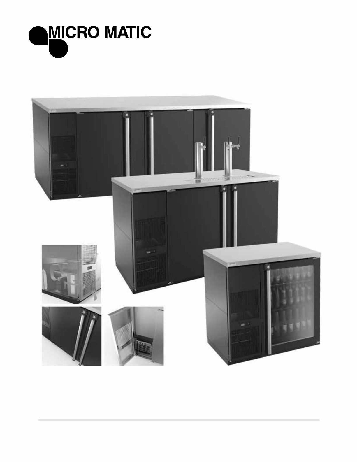
PRO-LINE™ REFRIGERATION E-SERIES
USER MANUAL
// www.micromatic.com
™

CONTENTS
1 RECEIVING AND INSPECTING 3
2 SPECIFICATIONS 4
3 INSTALLATION 5
3.1 UNCRATING 5
3.2 SEALING 5
3.3 CLEANING OF CABINET 5
3.4 LOCATION 6
3.5 TAPPING INSTRUCTIONS 7
3.6 DATA PLATE 8
3.7 ELECTRICAL CONNECTIONS 8
3.8 SHELVING INSTALLATION 9
4 OPERATIONS 9
4.1 MECHANICAL TEMPERATURE CONTROL 9
4.2 DESCRIPTION OF BUTTONS ON THE CONTROLLER 10
4.3 ELECTRONIC TEMPERATURE CONTROL 11
4.4 DEFROST 12
5 MAINTENANCE 13
5.1 STAINLESS STEEL CARE AND CLEANING 13
5.2 CLEANING THE CONDENSER COIL 14
5.3 DRAIN MAINTENANCE 15
6 TROUBLESHOOTING 16
7 WIRING DIAGRAMS 17
8 WARRANTY 19
9 TECHNICAL INFORMATION 20
// www.micromatic.com
2

1 // RECEIVING AND INSPECTING
Upon receiving your new Micro Matic Pro-Line™ Refrigeration E-Series™ equipment,
check the package and the unit for any damages that may have occurred during
transportation. Visually inspect the exterior of the package. If damaged, open and
inspect the contents with the carrier. Any damage should be noted and reported on
the delivering carrier’s receipt.
In the event that the exterior is not damaged, yet upon opening, there is concealed
damage to the equipment notify the carrier immediately. Notication should be made
verbally as well as in written form. Request an inspection by the shipping company of
the damaged equipment. Retain all crating material until inspection has been made.
Finally, contact Micro Matic.
Open the compressor compartment housing and visually inspect package. Be sure
lines are secure and base is intact.
A NOTE FROM OUR QUALITY CONTROL MANAGER
Congratulations on your new purchase. We would like to welcome you to the Micro
Matic team. The unit in front of you is a great piece of equipment that will become one
of your most reliable tools in your daily operations for years to come!
Prior to shipping your unit, our trained service technicians tested your unit for a period
of 12 hours. This performance test was recorded and a copy of the results is included
with this service manual. During this test, our highly qualied personnel inspected your
machine for leaks, lose components, and improper noise levels. We also tested the
cooling performance in an effort to give you the best and most reliable unit possible.
// www.micromatic.com
3

2 // SPECIFICATIONS
Crated
Model Doors Tower Faucets Kegs HP AMP
Weight
Length Width Height BTU
(lbs)
MDD23-E 1 1 1 1 1/6 2.5 172 24.5" 30.5" 40" 850 5.64 oz
MBB/DD36-E 1 1 1 1 1/6 3.6 172 36.75" 29.5" 40" 850 6.35 oz
MBB/DD58-E 2 2 3 3 1/3 6.5 318 59.5" 29.5 37" 2400 9.8 oz
MBB/DD68-E 2 2 3 3 1/3 6.5 359 69.5" 29.5" 37" 2400 9.8 oz
MBB/DD78-E 3 2 4 4 1/3 6.5 377 80" 29.5" 37" 2400 9.8 oz
MBB/DD94-E 3 2 4 5 1/3 6.5 406 95.5" 29.5" 37" 2400 9.8 oz
Voltage 115v 60Hz
Crated
Model Doors Shelves HP AMP
Weight
Length Width Height BTU
(lbs)
MBB58DT-E 2 3 1/3 6.5 318 59.5" 29.5 37" 2400 9.8 oz
MBB58GDT-E 2 3 1/3 6.5 318 59.5" 29.5 37" 2400 9.8 oz
MBB58GSDT-E 2 3 1/3 6.5 318 59.5" 29.5 37" 2400 9.8 oz
MBB58SDT-E 2 3 1/3 6.5 318 59.5" 29.5 37" 2400 9.8 oz
Voltage 115v 60Hz
Refrigerant
Charge
(R-134 a)
Refrigerant
Charge
(R-134 a)
// www.micromatic.com
4

3 // INSTALLATION
3.1 UNCRATING
Cut and remove the outer packaging. Cut the (4) four clamps that hold the refrigerator
to the skid lift the unit off the skid. If machine was laid down during this operation leave
the cabinet up right for 24 hours before plugging into power source. To install draft
arm, rst place rubber washer over draft arm mounting holes in cabinet top and put
beer line connector down through hole. Next secure draft arm with four bolts provided.
To retain complete mobility of the cooler, the accessory CO2 tank (up to ve pounds in
size) must be placed inside the cabinet.
3.2 SEALING
WHEN SANITATION CODES REQUIRE SEALING TO FLOOR, THIS METHOD MAY
BE USED
1. Tip cabinet and apply a bead of silicone seal on bottom edge of the base.
2. Return cabinet to upright position and using proper equipment, lift cabinet into location.
Heavy appliances should not be used on the same circuit with the cooler.
CAUTION: If an extension cord is necessary, use only a three wire grounding type of
wire, size 16 AWG or heavier; do not exceed 20 feet in length. The use of ungrounded
cords or overloaded circuit voids compressor warranty.
3.3 CLEANING OF CABINET
The exterior of the cabinet is either black vinyl or stainless steel and should be cleaned
only with lukewarm water, taking care not to scratch the surface. Mild detergents are
also recommended. The interior can be cleaned in a similar manner. THE CONDENSER
MUST BE CLEANED AT REGULAR INTERVALS. FAILURE TO DO SO CAN CAUSE
COMPRESSOR MALFUNCTION AND WILL VOID WARRANTY.
Clean approximately every six months, depending upon usage, dust, etc. Pull cabinet
away from wall and thoroughly vacuum the condenser and surrounding surfaces.
// www.micromatic.com
5
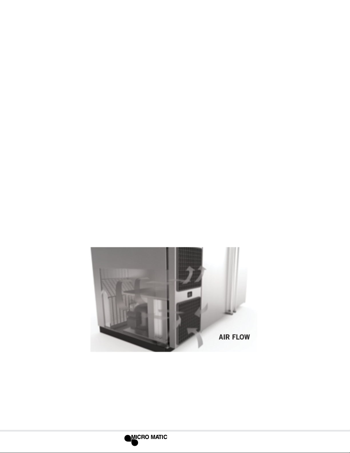
3.4 LOCATION
Units represented in this manual are intended for indoor use only. Be sure the location
chosen has a oor strong enough to support the total weight of the unit and contents.
For the most efcient operation, be sure to provide good air circulation inside and
outside of the unit.
NOTICE: This cooler is designed to maintain your beer temperature within the most
desirable range of 32° to 38°F. You can expect this temperature with the proper
temperature control setting and in a normal environment. It is important to understand
that when the beer is purchased, it must be installed inside the cooler as soon as
possible to avoid excessive warm-up of the beer. If this happens, it may take many
hours for the temperature to be reduced to the desirable range. No provision is made
for rapid cooling of beer which has become too warm.
INSIDE CABINET
The rst cleaning must be made when you unpack the unit and before switching it on.
Clean it with water and a mild detergent.
OUTSIDE CABINET
Be sure the unit has good air circulation in front. Avoid hot corners and locations near
stoves and ovens. The place where the refrigerator is placed must be open and free of
dust and debris.
// www.micromatic.com
6

3.5 TAPPING INSTRUCTIONS
The largest keg this cooler accepts is a half keg. The Sankey type is the most modern
and easiest of all to tap with the available taps. The type of keg and tap you use
will depend on the brand of beer your purchase. Your beer distributor can provide
additional instructions and tips on how to maintain the beer to your satisfaction.
Following these tapping instructions, place the keg in front of cabinet for tapping. After
all connections are complete and checked for leaks, place the CO2 bottle in the rear
(inside) of cabinet with the pressure gage visible for reading, then place the keg in
position, allowing the door to be closed completely without interference. Make certain
that beer line and keg are not touching the evaporator.
HOW TO TAP A KEG OF BEER (SANKEY-TYPE)
1. Connect line from pressure source to gas nipple (use clamp). Using coupling
washer connect beer line to thread on probe. Holding ats on probe with wrench
tighten wing nut or hex nut on beer hose.
2. Align tap with lugs in barrel, insert tap.
3. Turn tap body handle ¼ turn clock wise until tight to secure tap to barrel. Turn on
pressure regulator.
4. Pull out tap handle and push down, tapping keg – beer will ow to faucet.
// www.micromatic.com
7
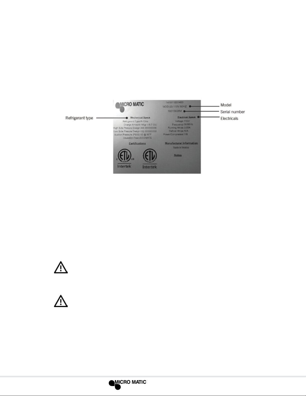
3.6 DATA PLATE
The data plate in located inside the unit, near the top front left corner. Under no
circumstances should the data plate be removed from the unit. The data plate is
essential to identify the particular features of your unit and is of great benet to
installers, operators and maintenance personnel. It is recommended that, in the event
the data plate is removed, you copy down the essential information in this manual for
reference before installation.
3.7 ELECTRICAL CONNECTIONS
Refer to the amperage data in this manual or on data plate and your local code or the
National Electrical Code to be sure unit is connected to the proper power source. Verify
correct incoming voltage according to the Data Plate information.
A protected circuit of the correct voltage and amperage must be run for connection
of the supply cord. Unit must be grounded and connected in accordance with NEC
Article 422 Appliances.
DANGER: Power must be turned off and disconnected from the power source
whenever performing maintenance, repair or cleaning the condensing unit. If
unit still running when power is off, disconnect power at the circuit breaker
before unplugging the unit.
WARNING: Unit and compressor warranties are void if failure is due to improper
electrical installation.
// www.micromatic.com
8

3.8 SHELVING INSTALLATION
1. Hook shelf rails onto shelf pilasters
2. Position all two shelf rails equal in distance from the oor for level shelves.
3. Wire shelves are oriented so that cross support bars are facing down.
4. Place shelves on shelf clips making sure all corners are seated properly.
4 // OPERATIONS
4.1 MECHANICAL (ANALOG) TEMPERATURE CONTROL
Before you connect the unit to the power supply, verify the thermostat is NOT in the OFF
position (the position of the thermostat must be different than zero). If the thermostat
is in the OFF position, the compressor will not run. Keep in mind, the evaporator fan
and lights will still have power while the thermostat is in the OFF position.
The knob of the thermostat is the temperature controller. This is located inside the
cabinet. Please be sure that the knob of thermostat is pointing to the yellow arrow
(Figure #3). This position is recommended by the factory to assure correct function of
the equipment (see Figure #1 below).
NOTE: Keep in mind, if you move the knob to a different position than the
position recommended from factory, the temperature will change, as well.
The knob position near the number one, gives you the warmest temperature and the
knob position near the number seven, gives you the coldest temperature.
// www.micromatic.com
9

4.2 DESCRIPTION OF BUTTONS ON MODELS WITH DIGITAL CONTROLLER
The Pro-Line
desirable range of 36° to 38°F. You can expect the Pro-Line™ unit to maintain
temperature with the proper temperature control setting and in a normal environment.
If a different setting is desired, follow these
instructions to adjust the thermostat.
™
dispenser is designed to maintain keg temperature within the most
To display target set point,
in programming mode
it selects a parameter or
conrms an operation
To start a manual defrost
(only XR02CX)
In programming mode it
browses the parameter
codes or increases the
displayed value
In programming mode it
browses the parameter
codes or decreases the
displayed value
Symbol Mode Operation
On Compressor enabled
Flashing Anti short cycle delay enabled (AC parameter)
On Defrost in progress
Flashing Dripping in progress
On Measurement unit
Flashing Programming mode
On Measurement unit
Flashing Programming mode
10
// www.micromatic.com

4.3 ELECTRONIC (DIGITAL) TEMPERATURE CONTROL
HOW TO SEE THE SET POINT
1. Push and immediately release the key, the set point will be displayed.
2. Push and immediately release the key or wait about ve (5) seconds to return
to normal display.
HOW TO CHANGE THE SET POINT
1. To change the set point number, push the key for more than two (2) seconds.
2. The number of the set point will be displayed and the “ ” or “ ” LED will blink.
3. To change the set number push the arrow up or down keys within ten (10) seconds.
4. To hold the new set point number push the key again or wait ten (10) seconds.
NOTE: The minimum value that you can set in the controller is 32°F (0°C) and the
maximum value you can set is 40°F (4.4°C)
4.4 DEFROST
The equipment with electronic controller will not require manual defrost due the
equipment has an automatic defrost every 6 hours. If a manual defrost is required
push and hold the defrost button for 5 seconds then the equipment will start defrost.
For equipment with manual thermostat a manual defrost could be required, unplug the
equipment from the power supply for 15 minutes and leave the door open. Continue
until ice melts.
// www.micromatic.com
11

5 // MAINTENANCE
5.1 STAINLESS STEEL CARE AND CLEANING
Proper cleaning of stainless steel requires soft cloths; never use steel pads, wire
brushes or scrapers!
Cleaning solutions need to be alkaline or non-chloride cleaners. Any cleaner containing
chlorides will damage the protective lm of the stainless steel. Chlorides are also
commonly found in hard water, salts, household and industrial cleaners. If cleaner
containing chlorides is used be sure to rinse repeatedly and dry thoroughly upon
completion.
Routine cleaning of stainless steel can be done with soap and water. Extreme stains
or grease should be cleaned with a non-abrasive cleaner and plastic scrub pad. There
are also stainless steel cleaners available which can restore and preserve the nish of
the steel's protective layer.
Never use an acid based cleaning solution! Many food products have an acidic content
which can deteriorate the nish. Be sure to clean ALL food products from any stainless
steels surface. Common items include peppers, tomatoes and other vegetables.
5.2 CLEANING THE CONDENSER COIL
DANGER: Power must be turned off and disconnected from the power source
whenever performing maintenance, repair or cleaning the condensing unit.
Disconnect unit from power supply. Remove front bottom panel and carefully slide out
the condensing unit. The condenser coil requires regular cleaning; recommended is
every 30 – 60 days, depending on the accumulation of dust and grease.
If the buildup on the coil consists of only light dust and debris the condenser coil can
be cleaned with a simple brush. Heavier dust build up may require a vacuum or even
compressed air to blow though the condenser coil.
If heavy grease is present there are de-greasing agents available for refrigeration
use and specically for the condenser coils. The condenser coil may require a spray
with the de-greasing agent and then blown through with compressed air. Be sure all
electrical and mechanical parts are dry before turning on the power. Never use a high
pressure water wash for this cleaning procedure as water can damage the electrical
components located near or at the condenser coil! Do not place lter material in front
of condenser coil. This material blocks air-ow to the coil similar to having a dirty coil!
12
// www.micromatic.com

If you keep the condenser clean you will minimize your service expense and lower
your electrical costs. Failure to maintain a clean condenser coil can initially cause high
temperatures and excessive run times. Continuous operation with dirty or clogged
condenser coils can result in compressor failures.
Neglecting the condenser coil cleaning procedures WILL VOID YOUR WARRANTY
associated with the compressor or cost to replace the compressor!
To put back the condensing unit in its place, slide in the unit carefully. BE SURE
DRAIN PIPE IS LOCATED OVER THE PAN. Replace front bottom panel.
5.3 DRAIN MAINTENANCE
Each unit has a drain located inside the unit which removes the condensation from
the evaporator coil and evaporates it at an external condensate evaporator pan. Each
drain can become loose or disconnected from moving or bumping the drain. IF YOU
NOTICE EXCESSIVE WATER ACCUMULATION ON THE INSIDE OF THE UNIT
be sure the drain tube is connected from the evaporator housing to the condensate
evaporator drain pan.
IF WATER IS COLLECTED UNDERNEATH THE UNIT you may want to check the
condensate evaporator drain tube to be sure it is still located inside the drain pan. The
leveling of the unit is important as the units are designed to drain properly when on a
level surface, if your oor is not level this can also cause drain problems. Be sure all
drain lines are free of obstructions; typically food products are found blocking drain
lines causing water to back up and overow the drain pan.
// www.micromatic.com
13

5.4 PROCEDURE TO INSTALL THE AIR CHANNELS AND DRAFT TOWERS
(ONLY “DD” MODELS)
MODELS: MDD23-E, MDD58-E, MDD68-E, MDD78-E & MDD94-E
This procedure describes how to install the air channel needed to provide cold air
directly into the beer towers.
TOOLS NEEDED: Philips screwdriver
STEP 1 Locate the gaskets and bolts included in with your Tower. Place gasket
over the pre-drilled holes and place the 4 screws thru the tower base.
Align the tower with screws and gasket to the cabinet top as shown
below while dropping the beer line(s) thru the top of the unit (Figure #1).
STEP 2 Tighten the screws using the nuts found in your tower box (Figure #2).
STEP 3 Identify the “COLD AIR HOSE” (Figure #3) which is found inside of
the equipment.
STEP 4 Introduce the “COLD AIR HOSE” (Figure #4) which is found inside of
the equipment into the tower’s base hole.
Push the cold air hose as far as possible up into the tower body. Be sure
and secure cold air hose by hooking on to beer hose elbow.
14
// www.micromatic.com

6 // TROUBLESHOOTING
Sometimes, working failures are due to simple causes which can be solved by the user.
Before asking for the help of a qualied technician, you have to do some verication.
These failures are not covered by the warranty:
1. Refrigeration does not work.
a. Check the unit is still connected to power supply.
2. Refrigerator does not reach temperature.
a. Check the thermostat is not in OFF position.
b. Check the unit is not on defrost cycle.
c. Check gasket is in good condition and door is sealed.
d. Check fan is moving. Open the door press and hold door switch for verication.
e. Don’t put any food inside until unit is at temperature.
f. Be sure castors or legs were installed.
3. There is water under the refrigerator.
a. Check the drain pipe is over the pan.
b. Check cabinet is level.
// www.micromatic.com
15

WIRING DIAGRAMS
MDD23-E
16
// www.micromatic.com

MDD/BB36-94-E
Electronic
Controller
PROBES NTC
AMB. PROBE
dixell XR02CX
L
N
BLUE
BROWN
BROWN
Red Display
COM/VC
L
BLK SMOOTH
BLK STRIPED
YELLOW
BROWN
ROCKER SWITCH
EVAP
FAN
LINE NEUTRE
JUNCTION
BOX
BLUE
BROWN
BLUE
GDN
NEUTRE
BLK SMOOTH
BLK SMOOTH
BLK STRIPED
SIGNAL FROM
CONTROLLER
BLK BLK
WHT
COMP
BLK
COND
BLUE
FAN
GDN
LIGHT SWITCH
WHITE
BLUE
LAMP's
Piloto
BLUE
NOTE: The lamp is only included for glass door models,
check with your sales representative.
GDN
// www.micromatic.com
17

8 // WARRANTY
One Year Parts & Labor Warranty: Micro Matic warrants to
the rst-end-user purchaser (the “User”) that the Micro
Matic brand equipment sold here under, except for parts
and accessories which carry the warranty of a supplier
(the “Equipment”) will be free from defects in material
and factory workmanship under normal conditions of use
and maintenance for a period of (1) one year from the
date of Installation (Warranty Commencement date), but
in no event to exceed (15) fteen months from the date of
shipment. Warranty is Not Transferable
Warranty Coverage: If there is a defect in material or factory
workmanship covered by this Warranty reported to Micro
Matic during the period the applicable Warranty is in force
and effect, Micro Matic will repair or replace, at Micro
Matic’s option, that part of the Equipment that has become
defective. Micro Matic will cover labor cost within one year
from the Warranty Commencement date or 15 months
from shipment date, whichever occurs rst. Micro Matic
shall bear all labor costs in connection with the installation
of these replacement parts, provided that, the installation is
conducted by Micro Matic or its authorized representative.
Charges for warranty travel time to round trip total of (2) two
hours or up to 100 miles total. Any charges exceeding those
stated herein or overtime rates must have prior authorization
by Micro Matic.
Additional Four Year Compressor Part Warranty: In addition
to the warranty set above. Micro Matic warrants the
compressor (part only) for an additional four (4) years
based on the installation date. This warranty is for defects
both in workmanship and material under the normal and
proper use and maintenance service. The four (4) year
extended warranty only applies to hermetically sealed
parts of the compressor and does not apply to any other
part or component, including, but not limited to cabinet,
temperature control, refrigerant, motor starting equipment,
fan assembly, or any other electrical or mechanical
component.
The original purchaser shall be responsible for returning the
defective compressor to Micro Matic prepaid. This warranty
shall be void if the compressor, in Micro Matic’s sole
judgment, has been subjected to misuse, neglect, alteration
or accident, operated contrary to the recommendations
specied by the Unit manufacturer, repaired or altered by
anyone other than Micro Matic in any way so as, in Micro
Matic’s sole judgment, to affect its quality or efciency or if
the serial number has been altered, defaced or removed.
This warranty does not apply to a compressor in any
unit that has been moved from the location where it was
originally installed.
Parts Warranty Coverage: Micro Matic warrants all new
machine parts produced or authorized by Micro Matic to be
free from defects in material and workmanship for a period
of 90 days from the Warranty Commencement Date. If any
defect in material and workmanship is found to exist within
the warranty period, Micro Matic will replace the defective
part without charge. Defective parts become the property
of Micro Matic.
Micro Matic will have no responsibility to honor claims
received after the date the applicable Warranty expires.
Notwithstanding the foregoing, any claim with reference to
the Equipment or any parts therefore for any cause shall be
deemed waived unless submitted by the User to Micro Matic
within thirty (30) days after the date the User discovered,
or should have discovered, the claim. In connection with
all claims under this Warranty, Micro Matic will have the
right, at its own expense, to have its representatives inspect
the Equipment at the User’s premises and to request all of
User’s records pertaining to the Equipment to determine
whether a defect exists, whether the conditions set forth in
this Warranty have been satised, and whether or not the
applicable Warranty is in effect.
Exclusions from and Conditions to Warranty Coverage: This
Warranty does not cover parts or accessories, which (a) carry
the warranty of a supplier or (b) are, abused. Application of
this Warranty is further conditioned upon the following:
Installation: The Equipment must be properly installed in
accordance with Micro Matic installation procedures.
No Alteration. The Equipment must not have been modied
or altered from its condition at the date of original installation.
Proper Maintenance and Operation: The Equipment must be
properly maintained and operated in accordance with Micro
Matic maintenance and operating procedures. All service,
labor and parts must be acquired from Micro Matic or its
authorized service representative for the User’s area.
This warranty is void if failure is a direct result of handling
and/or transportation, re, water, accident, misuse, acts of
god, attempted repair by unauthorized persons, improper
installation, if serial number has been removed or altered,
or if unit is used for purpose other than it was originally
intended.
Failure to comply with any of these conditions will void this
Warranty. In addition, this Warranty does not cover defects
due to apparent abuse, misuse or accident.
The foregoing warranty is in lieu of and excludes all other
warranties not expressly set forth herein, whether express
or implied by operation of law or otherwise, including but
not limited to any representation of performance and any
implied warranties of title, non-infringement, merchantability
or tness for a particular purpose. No other warranties
are authorized on behalf of Micro Matic unless specically
issued by Micro Matic. Micro Matic shall have no liability
for incidental or consequential losses, damages including
without limitation or expenses, loss of sales, spoiled food,
prots or goodwill, claims whether or not on account of
refrigeration failure or punitive or exemplary damages
directly or indirectly arising from the sale, handling or use
of the Equipment or from any other cause relating thereto,
whether arising in contract, tort, warranty, strict liability or
otherwise.
Micro Matic’s liability here under in any case is expressly
limited, at Micro Matic’s election, to repair or replacement
of Equipment or parts therefore or to the repayment of, or
crediting the user with, an amount equal to the purchase
price of such goods.
18
// www.micromatic.com

9 // TECHNICAL INFORMATION
If further technical information is needed, please contact the Service Department
directly. Please have the model number and serial number.
Service Support: (800) 544-0400
servicerequest@nordon.com
// www.micromatic.com
19

www.micromatic.com // 866-327-4159
NORTHEAST
4601 Saucon Creek Road
Center Valley, PA 18034
(610) 625-4464
(610) 625-4466 (Fax)
SOUTHEAST
2364 Simon Court
Brooksville, FL 34604
(352) 799-6331
(352) 796-2429 (Fax)
01726-D0216 ©2016 Micro Matic USA, Inc. All Rights Reserved.
CENTRAL
10726 North Second Street
Machesney Park, IL 61115
(815) 968-7557
(815) 968-0363 (Fax)
WEST
19791 Bahama Street
Northridge, CA 91324
(818) 701-9765
(818) 701-9844 (Fax)
 Loading...