

Page 1
INSTALLATION, USE & MAINTENANCE GUIDE
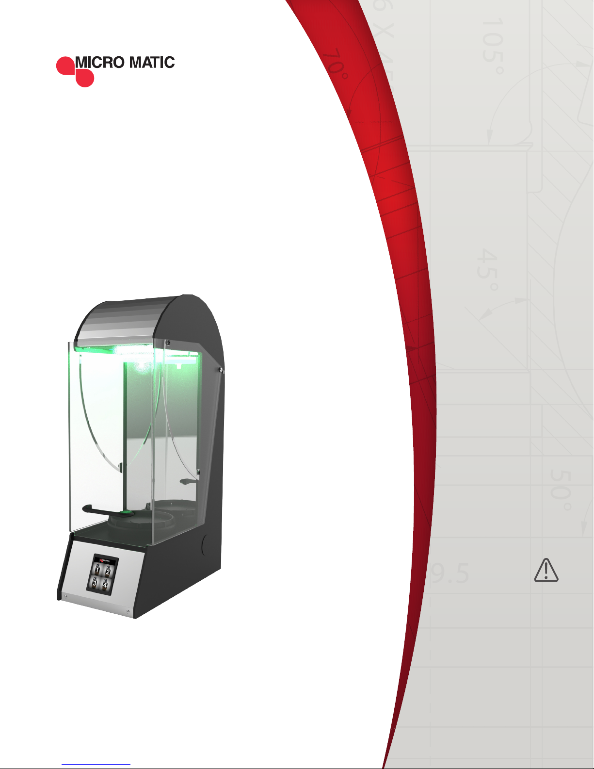
GROWLER
FILLER
GF-14515-G2
SAFETY
FIRST!
READ INSTRUCTIONS
COMPLETELY
Before getting started
please read this user
manual and at all times
follow the important
safety instructions.
VERSION 1.0
Page 2

TABLE OF
CONTENTS
1 GENERAL INFORMATION ........................................................................................................ 4-5
1.1 TERMS USED ...................................................................................................................... 4
1.2 LIMITATION OF LIABILITY ............................................................................................... 4
1.3 COPYRIGHT PROTECTION ............................................................................................... 4
1.4 CUSTOMER SERVICE ........................................................................................................ 4
1.5 GUARANTEE CONDITIONS .............................................................................................. 5
2. BASIC SAFETY ........................................................................................................................ 6-7
2.1 INTENDED USE ................................................................................................................. 6
2.1.1 GROWLER ........................................................................................................................ 6
2.1.2 PRODUCT ......................................................................................................................... 6
2.1.3 MISAPPLICATION .......................................................................................................... 6
2.1.4 SPACE REQUIREMENTS ................................................................................................ 7
2.1.5 WORKING ENVIRONMENT ............................................................................................ 7
2.2 CHANGES AND CONVERSIONS ...................................................................................... 7
2.3 SAFETY DEVICES .............................................................................................................. 7
3. TRANSPORT AND INSTALLATION ........................................................................................... 8
4. STRUCTURE AND FUNCTION .............................................................................................. 8-11
4.1 INLET ................................................................................................................................... 8
4.2 PROTECTIVE COVER ......................................................................................................... 9
4.3 CYLINDER PLATFORM ...................................................................................................... 9
4.4 CONTROL PANEL .............................................................................................................. 9
4.5 HOSE CONNECTIONS ..................................................................................................... 10
5. TECHNICAL SPECIFICATIONS ............................................................................................... 11
6. CONTROL PANEL PRESETS .................................................................................................... 12
6.1 FILLING PROCESS ........................................................................................................... 12
6.2 OPERATING STATUS ....................................................................................................... 12
7. CONTROLS AND INDICATORS ..........................................................................................13-15
7.1 FILLING NOZZLE ............................................................................................................. 13
7.2 PROTECTIVE COVER ....................................................................................................... 13
7.3 MAIN SWITCH ..................................................................................................................13
| 2
GROWLER FILLER, USE & MAINTENANCE GUIDE
Page 3

7.4 CONTROL PANEL ............................................................................................................ 14
7.4.1 "STANDBY" SCREEN .....................................................................................................14
7.4.2 "PRODUCTS" SCREEN .................................................................................................. 14
7.4.3 "GROWLER" SCREEN .................................................................................................... 15
7.4.4 "FILLING" SCREEN ........................................................................................................ 15
7.4.5 "CLEANING" SCREEN ................................................................................................... 15
7.4.6 "CLEANING" SCREEN ................................................................................................... 15
8. INSTALLATION AND FIRST CLEANING................................................................................. 16
8.1 SWITCHING "ON" THE DEVICE ...................................................................................... 16
8.2 BASIC CLEANING ............................................................................................................ 16
9. FILLING A GROWLER .......................................................................................................... 16-17
9.1 INSERTING/FILLING/REMOVING THE GROWLER ...................................................... 16
9.2 PAUSING OR ABORTING THE FILLING PROCESS ...................................................... 17
10. CLEANING AND MAINTENANCE ....................................................................................17-19
10.1 GROWLER DEDICATED FOR CLEANING.....................................................................18
10.2 CLEANING .................................................................................................................18-19
11. CONFIGURATION ..............................................................................................................20-27
11.1 REPORTING BUTTON .................................................................................................... 20
11.2 EVENT MEMORY BUTTON ........................................................................................... 20
11.3 SETTINGS BUTTON ......................................................................................................21
11.3.1 GENERAL BUTTON .................................................................................................... 21
11.3.2 WORKFLOW BUTTON ................................................................................................ 22
11.3.3 PRODUCTS BUTTON .................................................................................................. 22
11.3.4 DISPLAY BUTTON ...................................................................................................... 22
11.3.5 OPERATION BUTTON ................................................................................................ 23
11.3.6 CLEANING BUTTON ................................................................................................... 23
11.3.7 BOTTLES BUTTON ..................................................................................................... 24
11.3.8 TEXTS BUTTON .......................................................................................................... 24
12. PROGRAMMING DIFFERENT SIZE GROWLERS ............................................................ 25-27
13. TROUBLESHOOTING ............................................................................................................. 28
14. WARRANTY ............................................................................................................................. 29
| 3MICROMATIC.COM SUPPORT (866) 327-4159
Page 4

GENERAL
1
The contents of these operating instructions enable safe and proper handling of the Growler
Filler. Read the operating instructions completely before operating the lling machine. And
always keep the operating instructions within easy reach of the Growler Filler. The illustrations
in this manual may be different from the actual device.
INFORMATION
1.1 TERMS USED
DANGER
Causes serious injury or
death if not observed.
WARNING
Can result in serious injury
or death if not observed.
ATTENTION
May cause minor or
moderate injury.
NOTICE
Useful information or
general information.
1.2 LIMITATION OF LIABILITY
The manufacturer accepts no liability for:
• Damage caused by incorrect operation
• Inappropriate use
• Inadequate maintenance or cleaning
• Failure to observe the technical documentation
• Technical modications by the user
• Use of non-approved spare parts
1.3 INTELLECTUAL PROPERTY AND COPYRIGHT PROTECTION
All rights reserved. Any - including, but not limited to - duplication, dissemination and other
uses of the texts, graphics or other representations without the consent of the manufacturer.
Contact Information:
Micro Matic USA, Inc.
2364 Simon Court
Brooksville, FL 34604
1.4 CUSTOMER SERVICE
Micro Matic USA, Inc.
2386 Simon Court
Brooksville, FL 34604
(866) 327-4159
| 4
GROWLER FILLER, USE & MAINTENANCE GUIDE
Page 5
1.5 GUARANTEE CONDITIONS
The operator is obliged to:
• Meet local laws and regulations for the bottling of beverages
• Perform regular maintenance
• Perform regular rinsing and cleaning operations
| 5MICROMATIC.COM SUPPORT (866) 327-4159
Page 6

BASIC
2
SAFETY
2.1 INTENDED USE
The lling device is used for lling containers, hereinafter referred to as "growlers". Beverages
hereinafter referred to as "product". The operational safety of the lling device is only ensured
when used as intended. The use is only considered as intended if:
• The limits of applicability are observed.
• Carry out cleaning and maintenance according to the operating instructions.
• Cleaning and maintenance intervals according to the operating instructions and upon
request of the lling device.
The lling device is intended only for the processing of low-risk foodstuffs. Installation of the
growler ller is after prior installation by professionals for commercial use.
NOTE: When using the machine, be sure to use adequate hygiene before, during and after the
operation. Perform the cleaning and disinfection as described in chapter 10.
2.1.1 GROWLER
A growler is used for transporting or storing beverages. Suitable container, which corresponds
to the limits of applicability. These include:
• Drink Growlers
• Carafes
NOTE: Do not use any other vessels or growlers than those in these operating instructions.
NOTE: Before using the growlers, be sure that they are not cracked, chipped, etc.
NOTE: Danger of damage to the seal of the inlet by the use of growlers with low wall thickness
or sharp-edged growler opening. Leaks, deformation, and breakage of the growler can result.
• Only use growlers with a thick wall thickness.
• Make sure that the growler opening is completely on the lling seal.
• Visual inspection with the protective cover closed.
2.1.2 PRODUCT
The lling device is operated with beer. As soon as the product supply is empty, no liquid may
ow through the hose line. The system used must be checked by a qualied installer for leaks.
NOTE: The lling device may only be used with the instructions given in the operating instructions.
2.1.3 MISAPPLICATION
The lling device is intended for commercial and not for industrial use! No growlers or
beverages other than those described in the operating instructions may be used with the
lling device. The bottom and opening of the growler must be perpendicular to their vertical
axis. The Filler is not intended for use in conjunction with any high-risk foods. The use of
damaged, cracked or thin-walled growlers or growlers with a sharp-edged opening is not
permissible. The use of corrosive, oily, strongly acidic, caustic or other aggressive substances
(non-food) is prohibited. Filling other liquid foods other than those described in the operating
instructions is not permitted. Filling of gaseous substances (other than CO2) is prohibited.
| 6
GROWLER FILLER, USE & MAINTENANCE GUIDE
Page 7
2.1.4 SPACE REQUIREMENTS
DIMENSIONS MEASUREMENT (CM/INCHES)
Height 63 cm / 24.8"
Width 21 cm / 8.25"
Depth 40 cm / 15.74"
GROWLER MEASUREMENT (CM/INCHES)
Growler Diameter <12cm / 4.75"
Height 25 to 33cm / 9.84 to 12.99"
Make sure that:
• There is enough room to open the protective cover.
• There is enough room at the rear so that the hose lines can be connected.
2.1.5 WORKING ENVIRONMENT
The work environment of the unit must meet the required country and product-specic
requirements. Install the device so the protective cover can be opened easily and the hoses
are not kinking. The lling device is intended exclusively for use in well ventilated interior
spaces. The room temperature must be between 32 and 90˚F.
NOTE: Regularly clean the device according to the instructions in this manual to avoid
hygienic deciencies. Be careful when using the unit and the following hygiene requirements:
• Regularly clean the Growler lling nozzle and keg coupler. Make sure that the device is free
of product residues, mold, and bacteria.
• Use only clean growlers with the device.
2.2 CHANGES AND CONVERSIONS
Alterations and conversions of the lling device, which are not found in the instructions are
expressly prohibited. In the case of unauthorized changes, without explicit permission from
the manufacturer, will void any warranty claim.
2.3 SAFETY DEVICES
Protective Cover
The lling region of the lling device is provided with a protective cover. The protective cover
is equipped with two independent Reed Contacts, through which the lling device recognizes
when the protective cover is closed. Filling, cleaning, and ushing are only available when the
protective cover is closed.
WARNING
Risk of dangerous accumulations of carbon dioxide (CO2) in conned spaces or containers.
Carbon dioxide can be toxic at elevated concentrations.
• Ensure that the device is installed only by qualied personnel.
• Ensure adequate ventilation of the rooms in which the unit is installed and operated.
• Ventilate cabinets or areas below the unit. CO2 will collect at the lowest point rst.
| 7MICROMATIC.COM SUPPORT (866) 327-4159
Page 8
TRANSPORT
3
The lling unit is delivered in a cardboard box or air-packed in foam. It is recommended to
use the packaging of the ller for later transport and storage. Do not operate the unit if it is
damaged. Immediately contact Customer Service.
AND INSTALLATION
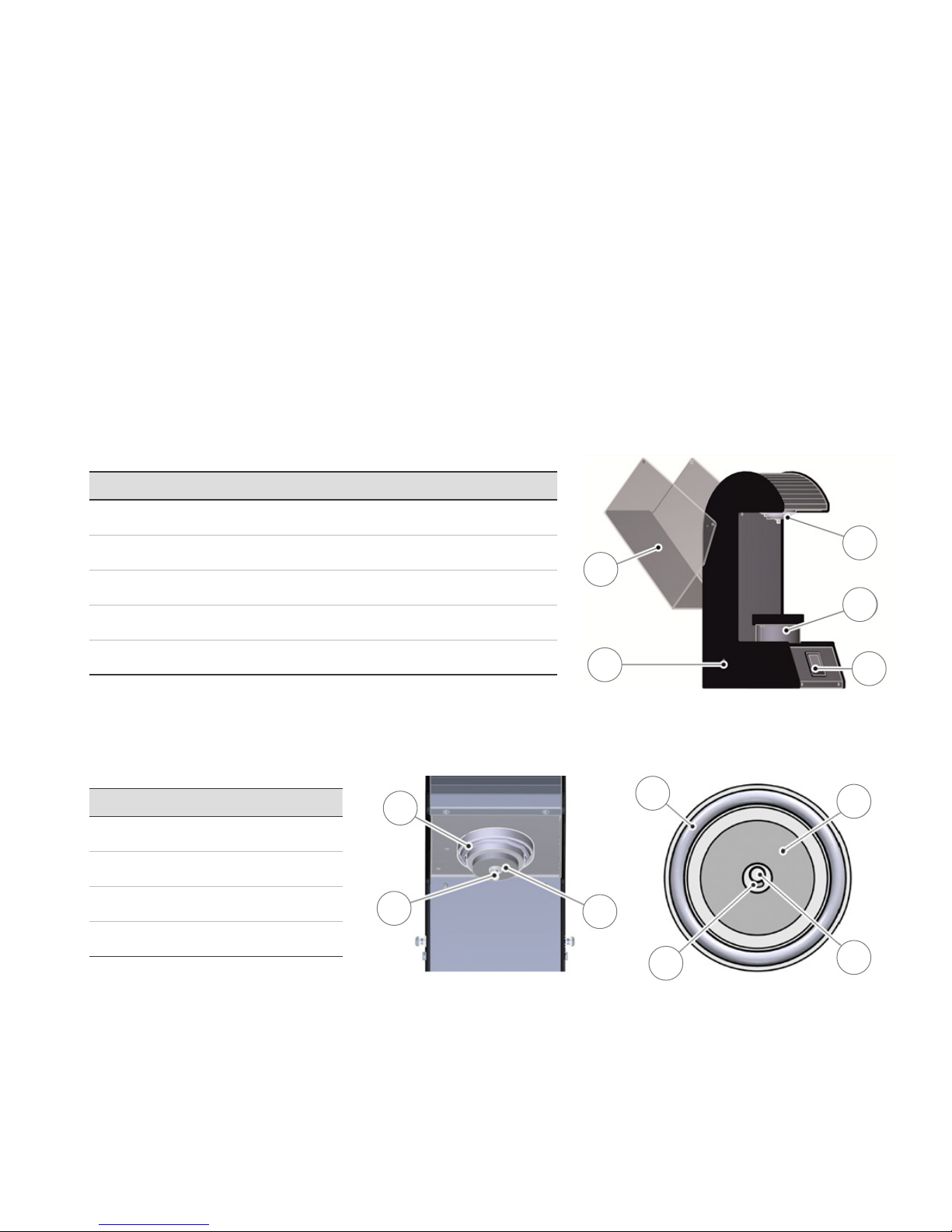
STRUCTURE
4
ITEM DESCRIPTION
1 Main switch
2 Protective cover
3 Filling nozzle
4 Growler platform
AND FUNCTION
2
3
4
5 Control panel
1
4.1 INLET
ITEM DESCRIPTION
6 Growler seal
7 LED lighting
8 Product outlet
9 Drain opening
Functionality
The spring-loaded lling nozzle activates a micro switch when a growler is inserted between
inlet and cylinder, and thus allows lling, cleaning, and ushing. The seal prevents the escape
of gas or liquid from the growler. The LED lighting serves as a light source and shows by
colored lighting. Operation status of the lling device is indicated by the LED lighting.
8
7
6
7
9
5
6
8
| 8
GROWLER FILLER, USE & MAINTENANCE GUIDE
Page 9
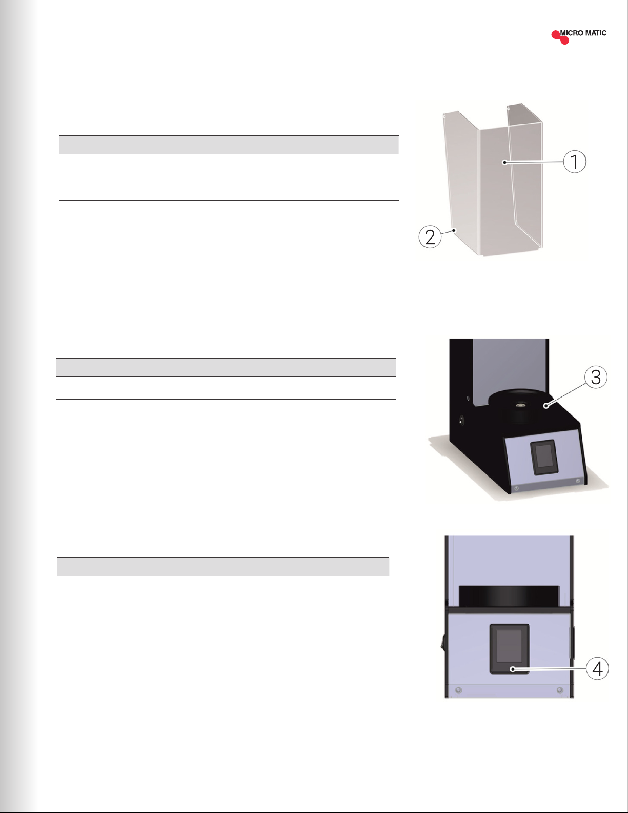
4.2 PROTECTIVE COVER
The transparent protective cover prevents access to the growler during the lling,
cleaning or ushing, and is designed to protect the user.
Construction
ITEM DESCRIPTION
1 Protective cover
2 Independent reed (magnetic) contacts (right / left)
Operation of Cover
The protective cover can be pivoted upwards until it stops. Once the lid is open, a
growler can be placed inside. During the lling process, the protective cover must be
closed. The device recognizes that the cover is closed.
4.3 CYLINDER PLATFORM
The growler platform serves as a base for a growler or an adapter.
Construction
ITEM DESCRIPTION
3 Platform
Functionality
A pneumatic cylinder under the growler rack lifts the growler or the cleaning adapter,
and clamps it between the growler platform and the lling nozzle.
4.4 CONTROL PANEL
The control panel is a color touch screen display. It displays the operating status of
the unit and allows for input during operation.
Construction
ITEM DESCRIPTION
4 Touchscreen
Functionality
On the control panel, you are able to access the lling, rinsing or cleaning features.
The control panel displays process steps, error messages, and settings.
| 9MICROMATIC.COM SUPPORT (866) 327-4159
Page 10
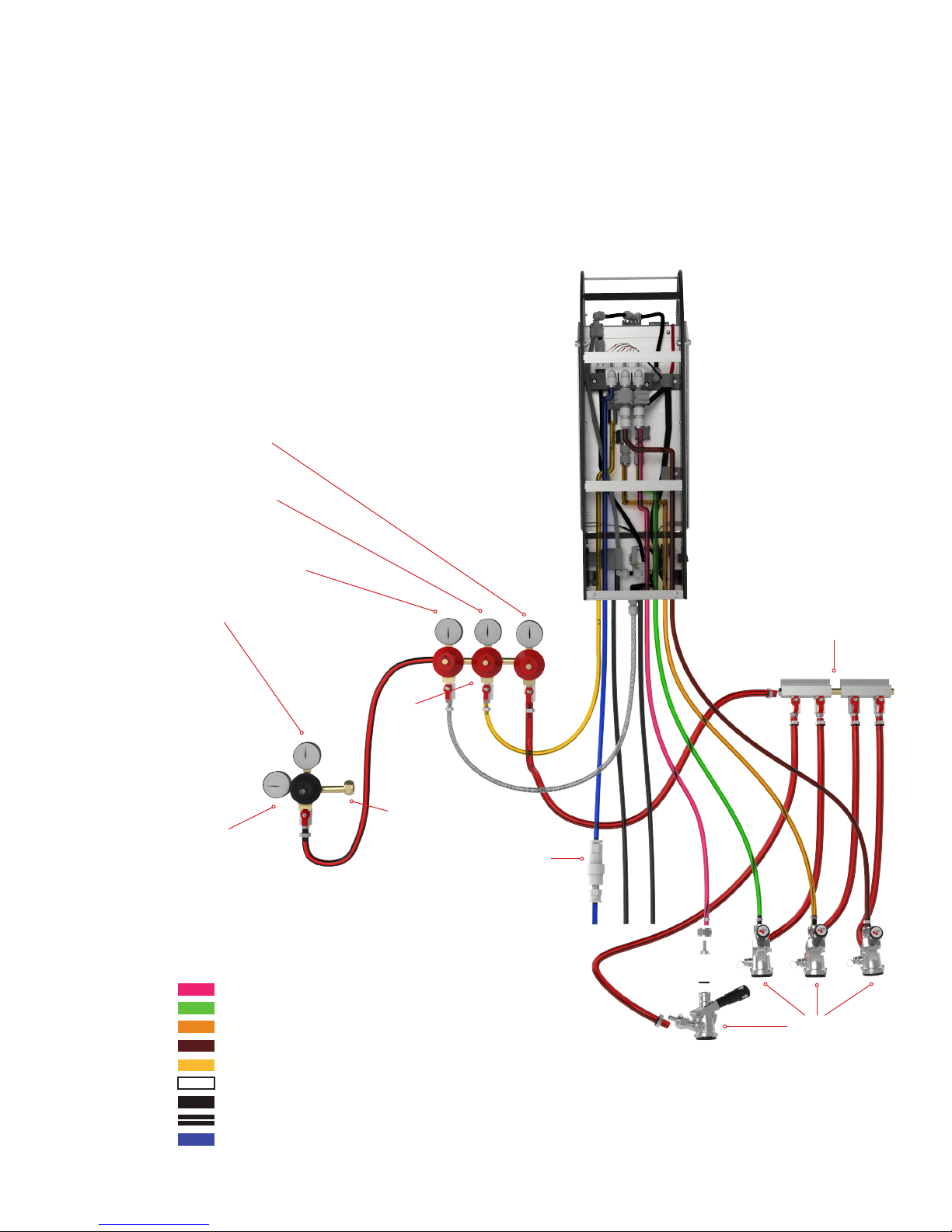
4.5 HOSE CONNECTIONS
The hose connections are used to connect the tubes to the lling unit.
Functionality
The supply lines for the product, water and gas are connected to the lling
device. The drainage line is used for the removal of excess growler contents, or
it can be used to drain cleaning uid when used with a quick release. Optionally,
compressed air can be used for the lift cylinder.
Pressure to the Kegs (Beers)
Typically, 12-15 PSI
CO2 Growler Purge Pressure
1 PSI higher than the beer
pressure (15-17 PSI)
Pneumatic Pressure (Platform Lift)
25-30 PSI Typically
Primary Pressure
40-50 PSI Typically
942B
Primary Regulator
GF-14515-G2
Growler Filler
(Back Cover Removed)
751-019
Gas Distributor
8033
Secondary
Regulators
Attach to CO2 Cylinder
1750352C
Water Regulator
(Included with Growler Filler)
Tube Color Reference
Beer 1 = Red
Beer 2 = Green
Beer 3 = Orange
Beer 4 = Brown
CO2 Purge = Yellow
CO2 Cylinder = White
Drain = Black
Drain = Double Black
Water = Blue
| 10
GROWLER FILLER INSTALLATION, USE & MAINTENANCE GUIDE
7485BS
Keg Couplers
Page 11

TECHNICAL
5
MECHANICAL/ELECTRICAL
Designation Growler Filler
Type Growler Filler 4 product V1
Power Standby 6W - Max. 75W
Operating Voltage 120VAC
Lift Cycle Max. 65 PSI
Filling Pressure Max. 43 PSI
Weight (when the growler is empty) 44 LBS
APPLIED PRESSURES PRESSURE (PSI)
Product Max. 43 PSI
Water Max. 43 PSI
CO
2
Lift Cycle Pressure
(must be dry and oil-free)
SPECIFICATIONS
Max. 43 PSI
Max. 65 PSI
| 11MICROMATIC.COM SUPPORT (866) 327-4159
Page 12

CONTROL PANEL
6
6.1 FILLING PROCESS
The lling process consists of the following process steps:
DESCRIPTION DURATION
Lift Growler 2.0 seconds
Gas Flooding 3.0 seconds
Pressure Build-up 3.0 seconds
Filling Timeout (Fill%) 240.0 seconds
Blow Out Filling Nozzle 2.0 seconds
Vent Gas 10.0 seconds
6.2 OPERATING STATUS
PRESETS
The current operating status of the lling device is indicated by the LED ring around the
lling nozzle default settings. List Operation Indicators:
STATUS LED FREQUENCY COLOR
Standby On Slow White
Ready On Slow Green
Error Flash Fast Red
Filling On Slow White
Filling Pause Flash Medium Yellow
Filling End Flash Fast Green
Rinsing On Slowly Blue
Cleaning On Medium White Blue
| 12
GROWLER FILLER INSTALLATION, USE & MAINTENANCE GUIDE
Page 13

CONTROLS
7
7.1 FILLING NOZZLE
The LED lighting around the lling head indicates the operation status of the unit using
colors and different ashing frequencies.
7.2 PROTECTIVE COVER
The protective cover can be opened by lifting using the handle. During the lling process,
the protective cover must remain closed. If the protective cover is opened during lling or
cleaning the process will be stopped. Pressure will be vented from the growler.
AND INDICATORS
7.3 MAIN SWITCH
The main switch can turn the lling device on ( "I") and off ( "O")
| 13MICROMATIC.COM SUPPORT (866) 327-4159
Page 14

7.4 CONTROL PANEL
7.4.1 "STANDBY" SCREEN
The control panel and indicators displayed can be
customized to the products and growlers used.
Colors, text, and images may differ from the gures.
While the device status is “Standby” the lling device is
inactive. Touch the Control panel to access the operating
status to the "product" screen.
This gure represents an example.
As part of the setup conguration, a standby timeout is
dened. After the standby time has passed the device will
change from the operating menus to the standby menu. The
default setting for Standby timeout is 10 seconds.
7.4.2 "PRODUCTS" SCREEN
The images of the products are congurable.
The images to the right are examples of the default.
CLEANING BUTTON
The Cleaning button opens the "cleaning" menu
on the control panel. Then there is access to
choose between "rinse" and "clean".
PRODUCT BUTTON
The Product button selects the pictured product for the
next lling and opens the screen "Growlers."
MAIN MENU
Hold the top red bar for 10 seconds to enter the
conguration menu.
Cleaning screen
| 14
GROWLER FILLER, USE & MAINTENANCE GUIDE
The default passcode is "12345"
Page 15

7.4.3 "GROWLER SCREEN"
7.4.4 "FILLING" SCREEN
The user can select which growler they
[X] BUTTON
are going to ll.
The button [X] cancels the selection
and opens the previous screen.
"START" BUTTON
This button will start or pause the lling.
"STOP" BUTTON
This button will end the lling process.
7.4.5 "CLEANING" SCREEN
[X] BUTTON
The button [X] cancels the selection and opens the previous screen.
RINSE BUTTON
Launches rinsing
Displays the current ushing
Stops the ush
CLEAN BUTTON
Opens the "cleaning" screen.
7.4.6 "CLEANING" SCREEN
[X] BUTTON
The button [X] cancels the selection and opens the previous screen.
PRODUCT LINE SELECTION
The Product Line Selection eld selects the line for the cleaning process. Multiple
selections are possible. An activated selection eld includes a check inside the frame.
"START" BUTTON
The Start button starts the cleaning process and allows the line cleaner to pause as
often as desired during the process.
"STOP" BUTTON
The Stop button stops the cleaning process.
| 15MICROMATIC.COM SUPPORT (866) 327-4159
Page 16

INSTALLATION
8
After the device is successfully and connected, the installer will perform the
initial conguration.
8.1 SWITCHING "ON" THE DEVICE
Engage the main switch to turn the power on ( "I").
8.2 BASIC CLEANING
Clean the growler ller before the initial start. Clean the exterior of the unit daily.
AND FIRST CLEANING
FILLING
9
Follow these steps to ll a growler with product. Make sure that the growler ller
is properly set up and mounted.
NOTE: GROWLER FILLER IS FACTORY PROGRAMMED FOR STANDARD
64 OZ GROWLERS
A GROWLER
9.1 INSERTING / FILLING / REMOVING THE GROWLER
Proceed as follows to place the growler for the lling process:
1. OPEN THE PROTECTIVE COVER
a) Swing the protective cover upward until it stops.
2. POSITION THE GROWLER
a) Place the growler in the middle of the growler platform.
b) When the growler is too short to reach the lling head, use an adapter (optional -
contact Micro Matic sales) to raise the growler allowing it to create a seal with the
lling head.
NOTE: Pay attention to make sure that the growler is stable on the platform. If the
growler is not stable, it could damage the unit or the growler. Verify that protruding
handles, straps, and fasteners, do not stop the protective cover from closing.
3. CLOSE PROTECTIVE COVER
a) Swing the Protective Cover down until it stops.
4. PRESS THE TOUCH SCREEN "START"
a) Follow screen prompts
5. REMOVING THE GROWLER:
a) Open the protective cover completely.
b) Remove the growler.
c) Close the protective cover.
| 16
GROWLER FILLER, USE & MAINTENANCE GUIDE
Page 17

9.2 PAUSE OR CANCEL FILLING
You have the option to pause or cancel the lling prematurely.
a) Press the play button to pause the lling process.
b) Press the pause button to resume the lling process.
WARNING
Lack of hygiene can occur by not properly cleaning the device using approved cleaning
solutions for cleaning the product lines and the exterior of the unit. If the product over ows,
then areas that have been impacted by the spill should be cleaned immediately.
• Use only for cleaning and disinfecting the device appropriate and recommended by the
manufacturer cleaning / disinfecting agents
CLEANING AND
10
Cleaning Canister
The cleaning canister (sold separately) serves to provide detergents for the cleaning
procedure.
Functionality
The cleaning container uses CO2 to push water and cleaning agent into the lling device
via the product line. Remove the lid to ll the cleaning container with the appropriate
cleaning chemical solution.
Cleaning Chemicals
To clean the growler ller, you need different cleaning chemicals for the following areas:
• Cleaning the product lines and growler ller
• External cleaning of surfaces
Cleaning the Product Lines
A caustic solution is suitable for the cleaning of the product lines. The detergent in liquid
form is added to the water in the cleaning canister.
The Growler Filler has two functions for cleaning:
• Rinsing function - ushes unit with clean water.
MAINTENANCE
CLEANING CANISTER
with valves installed
Part No. 201-420
CLEANING CHEMICAL
Part No. MM-B68
• Cleaning function - ushes the unit with a caustic cleaner.
When cleaning the exterior, use a scratch-free cloth and a disinfectant for beer
dispensers, which complies with the national hygiene standards.
| 17MICROMATIC.COM SUPPORT (866) 327-4159
Page 18

Cleaning Button
The Cleaning button opens the "cleaning" screen.
After 14 days, a notication will appear that the unit needs to be cleaned.
10.1 GROWLER DEDICATED FOR CLEANING
A cleaning growler and rinsing growler are needed for the rinsing and cleaning.
Designate a growler that will only be used during cleaning and a growler that
will only be used during rinsing.
Inserting cleaning growler:
1. OPEN PROTECTIVE COVER
2. POSITION THE CLEANING GROWLER
3. CLOSE PROTECTIVE COVER
DANGER
Risk of electric shock when preforming maintenance or repairs to the unit in
areas where electrical components are present. Contact with electricity can
cause serious injury.
• Turn off the power at the main switch ("O").
• Disconnect the device from the power supply by unplugging the unit from
the wall outlet.
10.2 CLEANING
Proceed as follows to perform the cleaning process.
Tools Required:
• Cleaning Canisters
NOTE: It is suggested to have a dedicated canister for water only, and a dedicated canister
with cleaning solution.
• Detergent
• Clear glass growler designated for cleaning
NOTE: Use proper personal protective equipment when using the cleaning chemicals.
Follow all directions provided by the manufacturer on proper handling of materials.
Cleaning Instructions
1. FILL CANISTER WITH WATER
a) Fill the cleaning container with lukewarm water.
b) Replace lid on cleaning canister.
2. START CLEANING PROCESS
a) Press on the touch screen to open the products menu. Touch water faucet icon in the
upper left corner of products screen.
| 18
GROWLER FILLER, USE & MAINTENANCE GUIDE
Page 19

b) Press the clean button to open the options for cleaning.
c) Select the check box of the line to be cleaned. Multiple selections are possible.
3. FLUSH THE FILLING DEVICE WITH WATER
a) Couple keg couplers to the cleaning canister lled with luke warm water.
b) Engage couplers to ll the canister with CO
2
c) Press the “Start” Icon on the control panel.
d) Allow water to ush all of the beer out of the lines.
4. ADD CLEANING CHEMICAL TO WATER IN CANISTER
a) Partially Fill the cleaning canister with lukewarm water, add (3) measuring caps of
3.33oz of Micro Matic Beer Line Cleaner per gallon.
b) Replace lid on cleaning canister.
5. SOAKING THE LINE WITH BEER LINE CLEANER
a) Tap the cleaning canister with the keg couplers.
b) Press the start icon on the control panel and ll all of the lines with Beer Line Cleaner.
c) Press the pause icon once the lines have been lled with Chemical. Wait 20 minutes
while the chemical soaks in the line.
d) After the chemical has soaked in the line for 20 minutes, press the play button to ush
the unit with chemical for another 10 seconds.
e) Carefully remove the cleaning growler and empty the contents. The growler contains
caustic, and care must be taken when disposing of the contents.
f) Rinse the growler out with cool clean water.
g) Replace the growler on the platform.
i ) Remove cleaning canister and replace with canister lled with rinse water.
h) Engage the keg couplers on the cleaning canister lled with water.
j) Activate the cleaning process again and allow the device to ush water though the
system for 1 minute. Emptying growler is necessary.
k) Press the “Stop” Icon.
l) Empty the contents of the growler and rinse out the growler.
m) Place the growler on the platform select all of the products. Press the start icon and
ll the growler with water.
n) Press the “Stop” icon and remove the growler. Use pH paper to test the pH of the water.
If the level is not below 8, repeat the rinse for 2 minutes. Continue to repeat until pH is
below 8>.
6. FILLING PRODUCT LINES
a) Select all of the product lines.
b) Untap all of the keg couplers from the water lled canister and tap the couplers to the
corresponding keg.
c) Press the “Start” icon and push the water out of the product lines. Once all of the
product lines have been cleared, press the stop icon.
d) Resume lling growlers in the regular manner.
| 19MICROMATIC.COM SUPPORT (866) 327-4159
Page 20

11CONFIGURATION
HIDDEN MENU
Using the main menu, operators can change the default settings that to better control the
lling process.
• Press the red header on the products menu for over ten seconds.
• Then a passcode entry screen will appear. The factory default pass code is 12345. The
changing of settings should only be done by qualied personnel.
11.1 REPORTING MENU
This screen shows how many growlers of each product have been lled.
The count can be reset as desired.
11.2 EVENT MEMORY BUTTON
The event memory button opens the "Event log" screen on the control panel:
The "event log" screen displays a history of all completed tasks on the device. Activities
such as cleaning and lling can be selected to view additional details. Up and down
scrolling by arrows is possible.
| 20
GROWLER FILLER, USE & MAINTENANCE GUIDE
Page 21

11.3 SETTINGS BUTTON
The Settings button opens the "Settings" screen on the control panel which has further
buttons for settings:
GENERAL
WORKFLOW
PRODUCTS
DISPLAY
SERIAL INTERFACE
OPERATION
CLEANING AND BOTTLES
TEXTS
11.3.1 GENERAL BUTTON
The General button will open the "General" screen on the control panel.
Here you will nd settings for:
LOGIN CODES: Open the menu on the device and enter the login code to enter the Extended
service menu on the device.
BACKLIGHT TIMEOUT: (0 = no dimming the display backlighting is always on)
STANDBY TIMEOUT: (the time is changed according to the in the standby screen)
LANGUAGE: (English, German, French, Italian)
LOGIN CODES
Open the menu on the device and enter the login code to enter the Extended service menu
on the device
| 21MICROMATIC.COM SUPPORT (866) 327-4159
Page 22

LANGUAGE
Choose your language: English, German, French, Italian
11.3.2 WORKFLOW
Workow button opens the "Workow" screen on the control panel:
LOADING (duration from start button to gas ooding)
GAS FLOODING (continuous ooding with gas)
PRESSURIZING (duration of applying pressure prior to lling)
BOTTLING TIMEOUT (elapsed time before lling process is automatically canceled)
INLET BLOWING OUT (time to empty the inlet or to blow out of the product)
VENTING (duration of the nal vent)
11.3.3 PRODUCTS
VIEW: By pressing the view button, selct, create and change products.
CALIBRATION: By pressing the calibration screen, calibrate each product for ow metr
steps/oz. The button portioning opens the "portioning" screen. Select (active or inactive)
products, to indicate the number of pulses / liter as the ow rate.
TITLE BAR: By pressing the title bar, select how menus should be displayed (title bar
color, title text color, and font size).
MONITORING DELAY: Watching ow rate before recognizing empty product.
11.3.4 DISPLAY
The button dislay will open the "Display" screen on the control panel:
GENERAL: Choose between displaying buttons with gradient or without.
STANDBY PICTURE: Select a desired standby image.
BACKGROUND COLOR: Change the background color
DECIMAL: Specify the desired separator for decimal values.
| 22
GROWLER FILLER, USE & MAINTENANCE GUIDE
Page 23

BACKGROUND COLOR
Change the background color
LED LIGHTING
Set the LED display for:
STANDBY MODE
READY (protective cover closed)
ERROR (such as protective cover open)
FILLING
FILLING PAUSE
FILLING END (protective cover not yet open)
RINSE
CLEAN
Changes can be made here for color, blinking / ashing, and frequency.
11.3.5 OPERATION BUTTON
The Workow utton opens the screen “Work Flow" on the control panel:
PAUSE AND RESUME FILLING OPERATIONS PAUSED.
AUTO CONTINUE FILLING OPERATIONS AFTER THE SET TIME.
AUTOMATIC DISCARD PAUSED FILLING OPERATIONS AFTER THE SET TIME.
IMMEDIATE CHANGE TO THE STANDBY SCREEN AFTER A FILLING.
11.3.6 CLEANING BUTTON
Settings for:
ACTIVATE THE CLEANING BUTTON THE SCREEN "CLEANING"
DURATION OF THE FLUSHING OF THE INLET AND OUTLET
(THROUGH THE EXHAUST VALVE)
DURATION OF THE FLUSHING OF THE COMPENSATOR
FLUSHING INTERVAL OF THE DEVICE
CLEANING INTERVAL OF THE DEVICE
| 23MICROMATIC.COM SUPPORT (866) 327-4159
Page 24

11.3.7 BOTTLES BUTTON
The Bottles opens the "growler-button" screen on the control panel:
PRESENTATION
Chose between default growlers or create new growlers to background color,
text color, font size.
Modify the image of the growlers.
PORTIONING
Select (active or inactive) growlers
Adjust lling volume in ounces
TITLE BAR
By pressing the Title bar, select how menus should be
displayed (title bar color, title text color, and font size).
11.3.8 TEXTS BUTTON
Here changes can be made to the texts of
the products and growlers.
| 24
GROWLER FILLER, USE & MAINTENANCE GUIDE
Page 25

PROGRAMMING
12
12.1 ACTIVATION INSTRUCTIONS FOR 32OZ GROWLER
Start at home screen. Hold down red bar until you get the password screen.
Enter 12345 and then press the check mark.
Select SETTINGS and then select BOTTLES
INSTRUCTIONS
Select VIEW and Select BOTTLE 1
| 25MICROMATIC.COM SUPPORT (866) 327-4159
Page 26

Scroll down with arrow and highlight GROWLER SIZE 2
by touching the screen. Select the picture icon.
Use right arrow until screen shows 32 oz bottle picture then select the
check mark.
Select check mark.
Select the X.
| 26
GROWLER FILLER, USE & MAINTENANCE GUIDE
Page 27

Select Portioning.
Select Bottle 1.
Hit the CE button THREE times.
Type in 1.00 then hit the check button. Hit the X button FOUR times to return to
the main homescreen.
MICROMATIC.COM ORDER TOLL-FREE 1-866-327-4159 | 27| 27MICROMATIC.COM SUPPORT (866) 327-4159
Page 28

ERROR AND
13
ERROR DESCRIPTION HANDLING
PROTECTIVE COVER OPEN
ERROR GROWLER!
ERROR CLEANING ADAPTER
ERROR LIMIT • Limit switch defect.
PRODUCT EMPTY
TROUBLESHOOTING
• Close the protective cover to the continue cleaning, rinsing or lling.
• Protective cover defective.
• Reed Contacts faulty: Check the magnets and vcontact.
• Growler is too small: Replace with appropriate matching adapter and growler for
the lling process.
• Growler missing: Place a suitable growler on the Growler platform.
• Cleaning Growler is missing: Place the cleaning growler on the platform
• Growler platform does not raise up to seal against lling head. Check the gas
supply pressure.
• Lift cylinder gas not present.
• Keg is empty. Connect a new keg.
• Monitoring delay too short.
• Defective ow meter.
EQUIPMENT RINSING
OVERDUE!
LINE CLEANING OVERDUE • Cleaning interval expired: Do one cleaning cycle before lling device use.
NO ENTRIES POSSIBLE /
BLACK SCREEN
GROWLER IS NOT FILLED
GROWLER PLATFORM DOES
NOT RAISE TO SEAL AGAINST
FILLING HEAD
FOAMY BEER
• Rinsing interval expired: Run a ushing cycle before you use the lling device.
• Check that the lling device is connected.
• Start the lling unit again by means of it turn the main switch off and on.
• If the screen is damaged, contact Customer Service.
• Check the product lines and CO2.
• Check the amount of product.
• Check calibration.
• Check the CO2 connection for leaks.
• Check the supply pressure of the lifting cylinder gas.
• Check if the gas is empty or the pressure to is too low.
• Leaking lines.
• Empty product.
• Pressure settings.
| 28
GROWLER FILLER, USE & MAINTENANCE GUIDE
Page 29

WARRANTY
14
STANDARD TERMS & CONDITIONS FOR USE OF PRODUCT. LIMITED WARRANTY.
INDEMNIFICATION.
By opening the packaging containing this product or by using such product in any
manner, you are consenting and agreeing to be bound by the following terms and
conditions. You are also agreeing that the following terms and conditions constitute
a legally valid and binding contract that is enforceable against you. If you do not
agree to all of the terms and conditions set forth below, you must promptly return
the product for a full refund prior to using the product in any manner.
ALL SALES ARE SUBJECT TO AND EXPRESSLY CONDITIONED UPON THE TERMS
AND CONDITIONS CONTAINED HEREIN, AND UPON PURCHASER’S ASSENT
THERETO. NO VARIATION OF THESE TERMS AND CONDITIONS SHALL BE BINDING
UPON MICRO MATIC USA, INC. UNLESS AGREED TO IN WRITING AND SIGNED BY
AN AUTHORIZED REPRESENTATIVE OF MICRO MATIC. Purchaser, by accepting the
product shall be deemed to have assented to the terms and conditions set forth
herein, notwithstanding any terms contained in any prior or later communications
from purchaser and whether or not Micro Matic shall specically or expressly
object to any such terms.
To the maximum extent permitted by law, with respect to Product proved to Micro
Matic’s satisfaction to be defective or nonconforming, Purchaser’s exclusive remedy
and Micro Matic’s maximum liability hereunder in any case is expressly limited to, at
Micro Matic’s election, (i) the repair or replacement of the Product without charge or
refund of the purchase price, upon return of the Product in accordance with Micro
Matic’s instructions above, or (ii) the repayment of, or crediting the Purchaser with,
an amount equal to the purchase price of the Product. To the maximum extent
permitted by law, Micro Matic is not responsible for, and Purchaser releases
Micro Matic from direct, special, punitive, incidental or consequential damages of
any kind arising from any use or failure of, or related in any way to the Product,
or based upon any contract, tort, strict liability or other legal or equitable theory,
including without limitation loss of beverage, loss of gas, loss of sales, loss of work,
downtime, or for any other labor or any other expense, damage or loss including
personal injury or property damage, unless such personal injury or property damage
is caused by Micro Matic’s gross negligence, even if Micro Matic has been advised
of the possibility of such damage or loss. Some states do not allow the exclusion
or limitation of incidental or consequential damages, so the above limitation or
exclusion may not apply to you.
USE OF PRODUCT
Purchaser agrees that no rights or licenses under Micro Matic’s patents shall be
implied from the sale of the Product, and Purchaser does not receive any right
under Micro Matic’s patent rights hereunder.
PURCHASER HEREBY GRANTS TO MICRO MATIC A NONEXCLUSIVE, WORLDWIDE,
UNRESTRICTED, ROYALTY-FREE, FULLY PAID-UP LICENSE, WITH THE RIGHT TO
GRANT AND AUTHORIZE SUB-LICENSES, UNDER ANY AND ALL PATENT RIGHTS IN
INVENTIONS COMPRISING MODIFICATIONS, EXTENSIONS, OR ENHANCEMENTS
MADE BY PURCHASER TO THE PRODUCT OR TO THE MANUFACTURE OR USE OF
THE PRODUCT (“IMPROVEMENT PATENTS”), TO MAKE, HAVE MADE, USE, IMPORT,
OFFER FOR SALE OR SELL ANY AND ALL PRODUCT; EXPLOIT ANY AND ALL
METHODS OR PROCESSES; AND OTHERWISE EXPLOIT IMPROVEMENT PATENTS
FOR ALL PURPOSES.
INFORMATION
Matic that Purchaser will use the Product in accordance with the Product label and
the instructions in this manual and in accordance with the practices of a reasonable
person and all laws and regulations now and hereinafter enacted; and Purchaser
shall not misuse the Product in any manner. Purchaser shall not reverse engineer,
decompile, disassemble or modify the Product. Purchaser acknowledges that Micro
Matic retains ownership or license rights of all patents, trademarks, trade secrets
and other proprietary rights relating to or residing in the Product and Purchaser
receives no rights to such intellectual property rights by virtue of its purchase of
Product other than as expressly set forth herein. Purchaser shall have no right to
use any trademarks owned or licensed to Micro Matic without the express written
permission of Micro Matic.
RELEASE AND INDEMNITY
By operating this Product, the Purchaser hereby takes full responsibility for any
risks associated with its use. Purchaser agrees to fully release, discharge, disclaim
and renounce any and all claims, demands, actions, causes of action and/or suits
in law or equity, now existing or hereafter arising, whether known or unknown,
against Micro Matic, and its ofcers, directors, employees, agents, successors
and assigns (collectively the “Released Parties”), with respect to the use of the
Product. Purchaser agrees to fully protect, defend, and indemnify, hold harmless the
Released Parties from and against all liability, losses, damages, costs, or expenses
of any nature, including without limitation, reasonable attorney’s fees, which they
may at any time suffer, incur, or be required to pay resulting from or arising out of (i)
any ordinary hazards that may be present in the normal operation of the Product; (ii)
any claim of injury, illness, or death resulting from consuming beverages dispensed
by the Product, whether or not prepared as specied by the Product; (iii) any hazards
from the use or misuse of the Product; (iv) any claim that the Product is defective,
negligently designed or manufactured in any manner, or otherwise determined to
be the cause of injury or death to persons, or damage to property, or both; (v) any
claim that the Product or the manufacture, sale, or labeling of the Product fails to
comply with any governmental requirement, or the labeling on the Product, or on
or within the packaging for the Product (including any instructions or warnings), is
inadequate in any manner; (vi) any claim that the Product should have been recalled
pursuant to any governmental requirement; (vii) Micro Matic’s negligence or willful
misconduct in supplying the Product; or (viii) any injuries, losses, or damages
(compensatory, direct, incidental, consequential or otherwise) of any kind arising in
connection with or as a result of possession or use of the Product. Purchaser shall
fully cooperate with the Released Parties in the investigation and determination of
the cause of any accident involving the Product which results in personal injury or
property damage and shall make available to the Released Parties all statements,
reports, recordings and tests made by Purchaser or made available to Purchaser by
others. If you do not consent to this indemnication, you must promptly return the
Product for a full refund prior to using the Product in any manner.
Purchaser acknowledges that, unless otherwise indicated on the Product label,
the Product has not received approval from any federal, state or local regulatory
agencies. Purchaser has the responsibility and hereby expressly assumes the risk
to learn the hazards involved in using the Product. Purchaser also has the duty to
warn Purchaser’s customers, employees, agents, assigns, ofcers, successors and
any auxiliary or third party personnel of any and all risks involved in using or handling
the Product. Purchaser agrees to comply with instructions furnished by Micro Matic
relating to the use of the Product and expressly represents and warrants to Micro
MICROMATIC.COM ORDER TOLL-FREE 1-866-327-4159 | 29| 29MICROMATIC.COM SUPPORT (866) 327-4159
| 29MICROMATIC.COM SUPPORT (866) 327-4159
Page 30

NOTES
| 30
GROWLER FILLER, USE & MAINTENANCE GUIDE
Page 31

NOTES
MICROMATIC.COM ORDER TOLL-FREE 1-866-327-4159 | 31| 31MICROMATIC.COM SUPPORT (866) 327-4159
Page 32

FOR MORE INFORMATION, TROUBLESHOOTING OR SERVICE PLEASE CALL SUPPORT AT (866) 327-4159
| 32
01938-D1018 ©2018 Micro Matic USA, Inc. All Rights Reserved. Micro Matic reserves the right to change specifications without notice.
 Loading...