


Quattro Ultima
User's Guide
Micromass UK Limited
Floats Road
Wythenshawe
M23 9LZ
Tel: +44 161 945 4170 Fax: +44 161 998 8915
Tudor Road
Altrincham
WA14 5RZ
Tel: +44 161 282 9666 Fax: +44 161 282 4400
http://www.micromass.co.uk
The instrument is marked with this symbol where high voltages are
present.
The instrument is marked with this symbol where hot surfaces are
present.
The instrument is marked with this symbol where the user should refer to
this User's Guide for instructions which may prevent damage to the
instrument.
Warnings are given throughout this manual where care is required to avoid personal
injury.
If the instrument is used in a manner not specified by the manufacturer, the protection
provided by the equipment may be impaired.
This manual is a companion to the MassLynx NT User's Guide supplied with the
instrument.
All information contained in these manuals is believed to be correct at the time of
publication. The publishers and their agents shall not be liable for errors
contained herein nor for incidental or consequential damages in connection with
the furnishing, performance or use of this material. All product specifications, as
well as the information contained in this manual, are subject to change without
notice.
Code: 6666511
Issue 3
© Micromass Ltd.

Quattro Ultima
User's Guide

Hardware Specifications
Dimensions 11
Weights 11
Lifting and Carrying 12
Power 13
Environment 13
Water Cooling 13
Exhausts 13
Rotary Pumps 13
API Gas Exhaust 13
Nitrogen 14
CID Gas 14
Quattro Ultima
User's Guide
Contents
Instrument Description
Overview 15
Vacuum System 16
Ionisation Techniques 17
Atmospheric Pressure Chemical Ionisation 17
Electrospray 17
Nanoflow Electrospray 17
Sample Inlet 17
MS Operating Modes 18
MS-MS Operating Modes 18
The Daughter Ion Spectrum 19
The Parent Ion Spectrum 20
MRM: Multiple Reaction Monitoring 21
The Constant Neutral Loss Spectrum 22
Data System 22
Front Panel Connections 23
Desolvation Gas and Probe Nebuliser Gas 23
Capillary / Corona 23
ESI / APcI 23
Front Panel Controls and Indicators 24
Status Display 24
Vacuum LED 24
Operate LED 24
Flow Control Valves 25
Divert / Injection Valve 25
Table of Contents

Quattro Ultima
User's Guide
Rear Panel Connections 26
Internal Layout 30
Event Out 26
Contact Closure In 26
Analog Channels 26
MUX 27
Data System 27
Water 28
Nitrogen Gas In 28
Exhausts 29
CID Gas 29
Power Cord 29
Mains Switch 29
Fuses 29
Rotary Control 29
ESD Earth Facility 29
Electronics 30
Mechanical Components 32
Routine Procedures
Start Up Following a Complete Shutdown 33
Preparation 33
Pumping 36
Measuring the Analyser Pressure 37
Using the Instrument 37
Start Up Following Overnight Shutdown 37
Preparation for Electrospray Operation 38
Preparation for APcI Operation 40
Operate 42
Automatic Pumping and Vacuum Protection 42
Overview 42
Protection 42
Transient Pressure Trip 42
Pump Fault 43
Power Failure 43
Tuning 44
Calibration 44
Data Acquisition 44
Data Processing 44
Setting Up for MS-MS Operation 44
Parent Ion Selection 44
Fragmentation 45
Shutdown Procedures 46
Emergency Shutdown 46
Overnight Shutdown 46
Complete Shutdown 47
Table of Contents

Tuning
Quattro Ultima
User's Guide
Automatic Start up and Shutdown 48
The Shutdown Editor 48
The Auto Control Tasks Page 49
The Shutdown Editor Toolbar 51
Loading Startup and Shutdown Files 52
Saving a Startup or Shutdown File 52
Printing Startup and Shutdown Files 53
Creating Startup and Shutdown Files 54
Running Startup and Shutdown Files 54
Overview 55
The Tune Page 56
Printing Tune Information 56
Experimental Record 56
Saving and Restoring Parameter Settings 56
Modifying the Peak Display 58
Changing the Display 60
Customise Plot Appearance 60
Trace 61
Intensity 61
Grid 61
AutoTune 62
Ion Mode 63
Scope Parameters 64
Gas Controls 64
Ramp Controls 64
Resetting the Zero Level 65
Controlling Readbacks 66
Changing Tune Parameter Settings 67
Source Voltages 67
Data Acquisition
Starting an Acquisition 69
Starting an Acquisition from the Tune Page 69
Parameters 70
Multiple Samples 71
Process 72
Automated Analysis of Sample List 72
Monitoring an Acquisition 74
The Acquisition Status Window 74
Chromatogram Real-Time Update 74
Spectrum Real-Time Update 74
Table of Contents

Quattro Ultima
User's Guide
Instrument Data Thresholds 75
System Manager 79
Stopping an Acquisition 80
The Function List Editor 80
MaxEnt 76
Profile Data 76
Centroid Data 76
SIR Data 76
Ion Counting Threshold 77
Profile Data - Spike Removal 78
Analog Data 79
Introduction 80
The Function List Editor Toolbar 82
Adding a New Function 82
Modifying an Existing Function 83
Copying an Existing Function 83
Removing a Function 83
Changing the Order of Functions 83
Setting a Solvent Delay 84
Analog Channels 84
Saving and Restoring a Function List 85
Setting up a Full Scan Function 86
Mass (m/z) 86
Cone Voltage 86
Method 86
Scan Duration (secs) 87
APcI Probe 87
Setting up a SIR Function 88
Channels 88
Method 89
Retention Window 89
Setting up MS-MS Scanning Functions 90
Mass 90
Collision Energy 92
Setting up a MRM Function 93
Setting up a Survey Function 93
Survey and MSMS Template Pages 94
MS to MSMS Switching 95
MSMS to MS Switching 97
Including and Excluding Masses 98
Monitoring Acquisitions 99
Mass Calibration
Introduction 101
Overview 102
Calibration Types 102
The Calibration Process 103
Table of Contents

Quattro Ultima
User's Guide
Electrospray 103
Introduction 103
Preparing for Calibration 104
Reference Compound Introduction 104
Tuning 104
Instrument Threshold Parameters 105
Calibration Options 106
Selecting the Reference File 106
Removing Current Calibrations 106
Selecting Parameters 107
Automatic Calibration Check 107
Calibration Parameters 108
Mass Measure Parameters 109
Performing a Calibration 110
Acquisition Parameters 112
Starting the Calibration Process 114
Checking the Calibration 116
Calibration Failure 118
Incorrect Calibration 120
Manual Editing of Peak Matching 121
Saving the Calibration 121
Verification 122
Electrospray Calibration with PEG 124
Atmospheric Pressure Chemical Ionisation 125
Introduction 125
Preparing for Calibration 126
Reference Compound Introduction 126
Tuning 126
Calibration Options 126
Selecting Reference File 126
Removing Current Calibrations 126
Selecting Calibration Parameters 126
Performing a Calibration 127
Static Calibration 127
Scanning Calibration and Scan Speed Compensation 132
Calibration Failure 135
Incorrect Calibration 136
Manual Editing of Peak Matching 137
Saving the Calibration 137
Manual Verification 138
Electrospray
Introduction 141
Post-column Splitting 144
Megaflow 145
Changing Between Flow Modes 145
Table of Contents

Quattro Ultima
User's Guide
Operation 146
Checking the ESI Probe 147
Obtaining an Ion Beam 148
Tuning and Optimisation 148
Megaflow Hints 154
Removing the Probe 154
Sample Analysis and Calibration 155
General Information 155
Typical ES Positive Ion Samples 156
Typical ES Negative Ion Samples 156
Chromatographic Interfacing 157
LC-MS Sensitivity Enhancement 158
Nanoflow Electrospray
Overview 159
Installing the Interface 160
Operation of the Camera System 163
Using the Microscope 163
Glass Capillary Option 164
Restarting the Spray 165
Nano-LC Option 166
Installation 166
Operation 167
Changing Options 168
Atmospheric Pressure Chemical Ionisation
Introduction 169
Preparation 170
Checking the Probe 171
Obtaining a Beam 172
Calibration 173
Hints for Sample Analysis 174
Tuning for General Qualitative Analysis 174
Specific Tuning for Maximum Sensitivity 174
Corona Current 175
Probe Position 175
Probe Temperature 175
Desolvation Gas 175
Removing the Probe 176
Maintenance and Fault Finding
Introduction 177
Cooling Fans and Air Filters 177
Table of Contents

Quattro Ultima
User's Guide
The Vacuum System 178
Vacuum Leaks 179
Pirani Gauge 179
Active Inverted Magnetron Gauge 179
Gas Ballasting and Rotary Pump Oil Recirculation 180
Oil Mist Filter 181
Foreline Trap 181
Rotary Pump Oil 182
The Source 183
Overview 183
Cleaning the Cone Gas Nozzle and Sample Cone 184
Removing and Cleaning the Ion Block 188
Removing and Cleaning the Ion Tunnel Assembly 192
Reassembling and Checking the Source 194
The Discharge Pin 195
The Electrospray Probe 196
Overview 196
Replacement of the Stainless Steel Sample Capillary 198
The APcI Probe 200
Cleaning the Probe Tip 200
Replacing the Probe Tip Heater 201
Replacing the Fused Silica Capillary 202
The Analyser 204
The Detector 204
Electronics 205
Fuses 205
Analog PCB 205
RF Power PCB 205
Power Backplane #2 205
Pumping Logic PCB 205
Power Sequence PCB 205
Rear Panel 205
Fault Finding Check List 206
No Beam 206
Unsteady or Low Intensity Beam 206
Ripple 206
High Noise Level in MRM Analyses 207
Chemical Noise 207
Electronic Noise 208
High Back Pressure 208
General Loss of Performance 209
Cleaning Materials 210
Preventive Maintenance Check List 211
Weekly 211
Monthly 211
Three-Monthly 211
Four-Monthly 211
Table of Contents

Quattro Ultima
User's Guide
Reference Information
Overview 213
Editing a Reference File 214
Positive Ion 215
Horse Heart Myoglobin 216
Polyethylene Glycol 216
PEG + NH4
Sodium Iodide and Caesium Iodide Mixture 217
Sodium Iodide and Rubidium Iodide Mixture 217
Negative Ion 218
Horse Heart Myoglobin 218
Mixture of Sugars 218
Sodium Iodide and Caesium Iodide (or Rubidium Iodide) Mixture 219
Preparation of Calibration Solutions 220
PEG + Ammonium Acetate for Positive Ion Electrospray and APcI 220
PEG + Ammonium Acetate for Positive Ion Electrospray
(Extended Mass Range) 220
Sodium Iodide Solution for Positive Ion Electrospray 221
Method 1 221
Method 2 221
Sodium Iodide Solution for Negative Ion Electrospray 221
+
216
Table of Contents

Dimensions
180mm
Quattro Ultima
User's Guide
Hardware Specifications
200mm
(pumping line)
1325mm
535mm
Weights
120mm
(ventilation)
700mm
Instrument: 150kg (330lb)
Data system
(computer, monitor and printer): 60kg (130lb)
Rotary pumps
E2M28: 40kg (90lb)
E1M18: 32kg (72lb)
Transformer (optional): 100kg (220lb)
Hardware Specifications
Page 11

Quattro Ultima
User's Guide
Lifting and Carrying
Warning: Persons with a medical condition, for example a back injury, which
prevents them from handling heavy loads should not attempt to lift the
instrument.
Before lifting the instrument proceed as follows:
Vent and power down the instrument.
Disconnect the instrument from the power and water supplies.
Disconnect power and tubing connections to the rotary pump from the rear of
the instrument.
Disconnect the API gas inlet and the exhaust lines from the rear of the
instrument.
Disconnect all connections to LC equipment.
If the instrument is to be moved over a large distance or in a confined space it is
recommended that any probes are removed from the API source.
The weight of the instrument is 150kg (330lb). Lifting equipment or suitably trained
personnel are required to lift or lower the instrument.
UK Health and Safety guidelines recommend that a minimum of six trained and
suitable personnel are required to lift a unit of this weight. The instrument should be
lifted from underneath the frame with one person at each corner of the instrument
supporting the instrument in line with, or close to, the feet upon which the instrument
stands. Two further people should support the instrument centrally.
Caution: Under no circumstances should the instrument be lifted by the probe or
the source enclosure.
Before undertaking any lifting, lowering or moving of the instrument:
•
Assess the risk of injury.
•
Take action to eliminate the risk.
•
Plan the operation.
•
Use trained people.
•
Refer to local or company guidelines before attempting to lift the instrument.
Micromass accept no responsibility for any injuries or damage sustained while lifting
the instrument.
Hardware Specifications
Page 12

Power
Environment
Short term variance (1.5 hours): ≤2°C (≤4°F)
Quattro Ultima
User's Guide
Instrument: 230V (+10%, -14%), 13A
Data system: 100-120V or 200-240V, 13A
Pumps: 230V (+10%, -14%), 13A
Ambient temperature: 15-28°C (59-82°F)
Overall heat dissipation
(excluding LC
and optional water chiller): 4.2kW maximum
Water Cooling
Heat dissipation into the water: 200W
Exhausts
Rotary Pumps
The rotary pumps must be vented to atmosphere (external to the laboratory) via a
fume hood or industrial vent.
API Gas Exhaust
The API gas exhaust must be vented to atmosphere (external to the laboratory).
Caution: The API gas exhaust line must not be connected to the rotary pump
exhaust line. In the event of an instrument failure, rotary pump exhaust could be
admitted into the source chamber producing severe contamination.
Humidity: Relative humidity ≤70%
Hardware Specifications
Page 13

Quattro Ultima
User's Guide
Nitrogen
A supply of dry, oil-free nitrogen at 6-7 bar (90-100 psi) is required.
CID Gas
Argon is required as collision gas. The supplied gas should be dry, of high purity
(99.9%) and at a pressure of approximately 350 mbar (5 psi).
Caution: The lines supplying nitrogen to the instrument must be clean and dry.
If plastic tubing is used it must be made of Teflon. The use of other types of
plastic leads to contamination of the instrument.
Caution: Operating with the CID gas at a significantly higher pressure results in
a fault.
Hardware Specifications
Page 14

Overview
Quattro Ultima
User's Guide
Instrument Description
Sample Inlet
Sampling Cone
and Ion Block
Ion Tunnels
Prefilter 1
Samples
from the liquid
introduction system
are introduced at
atmospheric pressure into the
ionisation source.
Ions are sampled through a series of orifices.
The ions are filtered according to their mass to charge
ratio ( ).
m
The mass separated ions undergo collision induced decomposition.
The fragment ions are filtered according to their mass to charge ratio.
The transmitted ions are detected by the photomultiplier detection system.
The signal is amplified, digitised and presented to the MassLynx NT™ data system.
Quadrupole 1
MassLynx NT
Data System
Collision Cell
Prefilter 2
Quadrupole 2
Detector
The Micromass Quattro Ultima is a high performance benchtop triple quadrupole mass
spectrometer designed for routine LC-MS-MS operation. Quattro Ultima may be
coupled to:
•
a HPLC system with or without an autosampler.
•
an infusion pump.
•
a syringe pump.
Ionisation takes place in the source at atmospheric pressure. These ions are sampled
through a series of orifices into the first quadrupole where they are filtered according
to their mass to charge ratio (m).
The mass separated ions then pass into the hexapole collision cell where they either
undergo collision induced decomposition (CID) or pass unhindered to the second
quadrupole. The fragment ions are then mass analysed by the second quadrupole.
Finally the transmitted ions are detected by a conversion dynode, phosphor and
photomultiplier detection system. The output signal is amplified, digitised and
presented to the data system.
Instrument Description
Page 15

Quattro Ultima
User's Guide
Vacuum System
Vacuum is achieved using two direct drive rotary pumps, and two turbomolecular
pumps.
The rotary pumps are mounted on the floor external to the instrument. The E1M18
pumps the ion source block, while the E2M28 pumps the first ion tunnel and also
backs the turbomolecular pumps. The E1M18 has an automatic gas ballast control
valve mounted in the oil return line from the mist filter. This solenoid valve is opened
whenever the E1M18 is switched on, allowing continuous recirculation of the pump
oil provided that the manual gas ballast valve on the pump is left open.
The turbomolecular pumps evacuate the analyser and ion transfer region. These pumps
are both water cooled.
Vacuum measurement is by an active inverted magnetron (Penning) gauge for the
analyser and a Pirani gauge for the gas cell. The Penning gauge acts as a vacuum
switch, switching the instrument out of the
OPERATE mode if the pressure is too high.
The speed of each turbomolecular pump is also monitored and the system is fully
interlocked to provide adequate protection in the event of a fault in the vacuum
system, a failure of the power supply or vacuum leaks.
Instrument Description
Page 16

Ionisation Techniques
Two atmospheric pressure ionisation techniques are available.
Atmospheric Pressure Chemical Ionisation
Atmospheric pressure chemical ionisation (APcI) generally produces protonated or
deprotonated molecular ions from the sample via a proton transfer (positive ions) or
proton abstraction (negative ions) mechanism. The sample is vaporised in a heated
nebuliser before emerging into a plasma consisting of solvent ions formed within the
atmospheric source by a corona discharge. Proton transfer or abstraction then takes
place between the solvent ions and the sample. Eluent flows up to 2 ml/min can be
accommodated without splitting the flow.
Electrospray
Electrospray (ESI) ionisation takes place as a result of imparting a strong electrical
field to the eluent flow as it emerges from the nebuliser. producing an aerosol of
charged droplets. These undergo a reduction in size by solvent evaporation until they
have attained a sufficient charge density to allow sample ions to be ejected from the
surface of the droplet (“ion evaporation”).
Quattro Ultima
User's Guide
A characteristic of ESI spectra is that ions may be singly or multiply charged. Since
the mass spectrometer filters ions according to their mass-to-charge ratio, compounds
of high molecular weight can be determined if multiply charged ions are formed.
Eluent flows up to 1 ml/min can be accommodated although it is often preferable with
electrospray ionisation to split the flow such that 100 to 200 µl/min of eluent enters
the mass spectrometer.
Nanoflow Electrospray
The optional nanoflow interface allows electrospray ionisation to be performed in the
flow rate range 5 to 1000 nanolitres per minute.
For a given sample concentration, the ion currents observed in nanoflow are
comparable to those seen in normal flow rate electrospray. Great sensitivity gains are
therefore observed when similar scan parameters are used, due to the great reductions
in sample consumption.
Sample Inlet
Sample is introduced from a suitable liquid pumping system along with the nebulising
gas to either the APcI probe or the electrospray probe. For nanoflow electrospray,
metal coated glass capillaries allow the lowest flow rates to be obtained while fused
silica capillaries are used for flow injection analyses or for coupling to nano-HPLC.
Instrument Description
Page 17

Quattro Ultima
User's Guide
MS Operating Modes
Source MS1 Collision Cell MS2 Detector
MS1 Collision Cell MS2
MS
MS2
The MS1 mode, in which MS1 is used as the mass filter, is the most common and
most sensitive method of performing MS analysis. This is directly analogous to using
a single quadrupole mass spectrometer.
The MS2 mode of operation is used, with collision gas present, when switching
rapidly between MS and MS-MS operation. It also provides a useful tool for
instrument tuning and calibration prior to MS-MS analysis, and for fault diagnosis.
Resolving RF Only (Pass all masses)
RF Only (Pass all masses) Resolving
MS-MS Operating Modes
The basic features of the four common MS-MS scan functions are summarised below.
Daughter Ion
Spectrum
(parent mass selection)
MS1
Static
Collision
Cell
MS2
Scanning
Parent Ion
Spectrum
Multiple Reaction
Monitoring
Constant Neutral
Loss Spectrum
Instrument Description
Page 18
Scanning
Static
(parent mass selection)
Scanning (synchronised
with MS2)
RF only
(pass all
masses)
Static
(daughter mass
selection)
Static
(daughter mass
selection)
Scanning (synchronised
with MS1)

The Daughter Ion Spectrum
This is the most commonly used MS-MS scan mode. Typical applications are:
Structural elucidation (for example peptide sequencing).
•
Method development for MRM screening studies:
•
Identification of daughter ions for use in MRM “transitions”.
Optimisation of CID tuning conditions to maximise the yield of a specific
daughter ion to be used in MRM analysis.
Example:
Daughters of the specific parent at m 609 from reserpine in electrospray
positive ion mode.
Quattro Ultima
User's Guide
The result:
MS1
static at m/z 609
(parent mass)
Collision Cell
RF only
(pass all masses)
MS2
scanning from
m/z 100 to 650
Instrument Description
Page 19

Quattro Ultima
User's Guide
The Parent Ion Spectrum
Typical application:
Structural elucidation.
•
Complementary or confirmatory information (for daughter scan data).
Example:
Parents of the specific daughter ion at m 195 from reserpine in electrospray
positive ion mode.
The result:
MS1
scanning from
m/z 50 to 650
Collision Cell
RF only
(pass all masses)
MS2
static at m/z 195
(daughter mass)
Instrument Description
Page 20

MRM: Multiple Reaction Monitoring
This mode is the MS-MS equivalent of SIR (Selected Ion Recording). As both MS1
and MS2 are static, this allows greater “dwell time” on the ions of interest and
therefore better sensitivity (~100×) compared to scanning MS-MS.
Typical application:
Rapid screening of “dirty” samples for known analytes.
•
Drug metabolite and pharmacokinetic studies
Environmental, for example pesticide and herbicide analysis.
Forensic or toxicology, for example screening for target drugs in sport.
Example:
Monitor the transition (specific fragmentation reaction) m 609 → 195 for
reserpine in electrospray positive ion LC-MS-MS mode.
Quattro Ultima
User's Guide
Collision Cell
MS1
static at m/z 609
(parent mass)
The result:
MRM does not produce a spectrum as only one transition is monitored. As in
SIR, a chromatogram is produced.
Time
LC-MRM
!
High specificity
!
Good signal / noise
RF only
(pass all masses)
!
!
Poor signal / noise
static at m/z 195
(daughter mass)
Time
LC-MS
Low specificity
MS2
Instrument Description
Page 21

Quattro Ultima
User's Guide
The Constant Neutral Loss Spectrum
The loss of a specific neutral fragment or functional group from an unspecified parent
or parents.
Typical applications:
Screening mixtures, for example during neonatal screening, for a specific class
•
of compound that is characterised by a common fragmentation pathway.
MS1
scanning
Collision Cell
RF only
(pass all masses)
MS2
scanning
The scans of MS1 and MS2 are synchronised. When MS1 transmits a specific
parent ion, MS2 “looks” to see if that parent loses a fragment of a certain mass.
If it does it registers at the detector.
The result:
The “spectrum” shows the masses of all parents that actually lost a fragment of a
certain mass.
Data System
The PC based data system, incorporating MassLynx NT™ software, controls the mass
spectrometer detector and, if applicable, the HPLC system, autosampler, syringe
pump, divert valve or injector valve.
The PC uses the Microsoft Windows NT graphical environment with colour graphics
and provides for full user interaction with either the keyboard or mouse.
MassLynx NT provides full control of the system including setting up and running
selected HPLC systems, tuning, acquiring data and data processing.
Analog inputs can be read by the data system so that, where applicable, a trace from a
conventional LC detector (for example UV or fluorescence) can be stored
simultaneously with the acquired mass spectral data. A further option is the ability to
acquire UV photodiode array detector data.
Comprehensive information detailing the operation of MassLynx NT is contained in
the MassLynx NT User’s Guide.
Instrument Description
Page 22

Front Panel Connections
Quattro Ultima
User's Guide
CAPILLARY / CORONA
ESI / APci
VACUUM
OPERATE
C.I.D. GAS
INJECTOR
STANDBY
DESOLVATION
GAS
NEBULISER
CONE GAS
LOAD
INJECT
LC Connection
High Voltage
Connection
Source
Connection
Desolvation Gas and Probe Nebuliser Gas
The PTFE gas lines for the desolvation gas and probe nebuliser gas are connected to
the front of the instrument using threaded metal fittings.
Capillary / Corona
The electrical connection for the ESI capillary or the APcI discharge pin is via the
coaxial high voltage connector.
ESI / APcI
The electrical connection for the APcI probe or the ESI heater is via the multi-way
connector. This is removed from the front panel by pulling on the metal sleeve of the
plug. Both the electrospray and APcI heaters use this connector.
Desolvation
Gas
Nebuliser
Gas
Instrument Description
Page 23

Quattro Ultima
C
User's Guide
Front Panel Controls and Indicators
CID Gas
ontrol
CAPILLARY / CORONA
ESI / APci
VACUUM
OPERATE
Cone Gas
Control
STANDBY
DESOLVATION
GAS
NEBULISER
C.I.D. GAS
INJECTOR
Desolvation
Gas Control
Nebuliser
Gas Control
CONE GAS
LOAD
INJECT
Status Display
The display on the front panel of the instrument consists of two 3-colour light emitting
diodes (LEDs).
The display generated by the Vacuum LED is dependent on the vacuum status of the
instrument. The Operate LED depends on both the vacuum status and whether the
Operate mode has been selected from the Data System.
The status of the instrument is indicated as follows:
Vacuum LED
Pumping Steady amber Pump fault Flashing red
Operate LED
Standby No indication
State Vacuum LED State Vacuum LED
Vented No indication Vacuum OK Steady green
State Operate LED State Operate LED
Transient pressure
trip
Steady amber
Operate Steady green RF trip Flashing red
Instrument Description
Page 24

Flow Control Valves
The Desolvation Gas, Cone Gas and Nebuliser needle valves are five-turn
valves. The CID Gas valve is a fifteen-turn valve. The flow increases as the valve is
turned counterclockwise.
Caution: To prevent damage to the CID Gas valve, take care not to
over-tighten when turning the supply off.
Divert / Injection Valve
Quattro Ultima
User's Guide
Load
Divert / Injection
Valve
The optional divert / injection valve may be used in several ways depending on the
plumbing arrangement:
•
As an injection valve, with the needle port and sample loop fitted.
•
As a divert valve, to switch the flow of solvent during a LC run.
•
As a switching valve to switch, for example, between a LC system and a syringe
pump containing calibrant.
This valve is pneumatically operated, using the instrument’s nitrogen supply.
Note that the valve is connected such that the nitrogen supply is always
connected to the valve, irrespective of the flow to the source and probe.
Control of the valve is primarily from the data system. The two switches marked
Load and Inject enable the user to override control of the valve when making loop
injections at the instrument.
Inject
Instrument Description
Page 25

Quattro Ultima
User's Guide
Rear Panel Connections
Event Out
Four outputs, Out 1 to Out 4, are provided to allow various peripherals to be
connected to the instrument. Switches S1 to S4 allow each output to be set to be
either a contact closure (upper position) or a voltage output (lower position).
Out 1 and Out 2, when set to voltage output, each have an output of 5 volts. The
voltage output of both Out 3 and Out 4 is 24 volts.
During a sample run Out 1 closes between acquisitions, and is used typically to
enable an external device to inject the next sample. The three remaining outputs are
reserved for future developments.
Contact Closure In
In 1 and In 2 inputs are provided to allow external device to start sample acquisition
once the device has performed its function (typically sample injection).
SCOPE
DATA SYSTEM
X
1V
+- +-
Y
CH3
MUX
1V
ANALOG CHANNELS EVENT OUT
CLOSURE
1V
IN
IN 2IN 1
CH4
1V
CONTACT
CH2
CH1
REFER TO
MANUAL BEFORE
CONNECTING TO
THESE PORTS
!
CAUTION !
OUT 4OUT 3OUT 2OUT 1
S4S3S2S1
Analog Channels
Four analog channel inputs are available, for acquiring simultaneous data such as a
UV detector output. The input differential voltage must not exceed one volt, though
full scale automatically adjusts from 1mV to 1V.
Instrument Description
Page 26

MUX
This 6-way connector connects the instrument to the MUX control base.
Data System
This RJ45 connector connects the instrument to the data system using the network
cable supplied.
Quattro Ultima
User's Guide
Instrument Description
Page 27

Quattro Ultima
y
User's Guide
Power
Cord
Electrostatic
Discharge
Earth (Ground)
Point
Rotary Pump
Control
Mains
Switch
Fuses
Water
Backing
Line
Source
Pumping Line
Hexapole
Pumping Line
To Rotar
Pumps
Water is used to cool the turbomolecular pumps.
CID Gas
Exhaust
Gas
ROTARY PUMP
CONTROL
ROTARY PUMP
CONTROL
CID
GAS
NITROGEN GAS
OUTLET INLET
Nitrogen
Gas In
1
0
ESD
EARTH
FACILITY
OUT IN
10 AMP (T)
10 AMP (T)
WATER
Water
Connections
Nitrogen Gas In
The nitrogen supply (100 psi, 7 bar) should be connected to the Nitrogen Gas In
push-in connector using 6mm PTFE tubing. If necessary this tubing can be connected
to ¼ inch tubing using standard ¼ inch fittings.
Caution: Use only PTFE tubing or clean metal tubing to connect between the
nitrogen supply and the instrument. The use of other types of plastic tubing
results in chemical contamination of the source.
Instrument Description
Page 28

Exhausts
CID Gas
Quattro Ultima
User's Guide
The exhaust from the rotary pump should be vented to atmosphere outside the
laboratory.
The gas exhaust, which also contains solvent vapours, should be vented via a separate
fume hood, industrial vent or cold trap.
The gas exhaust should be connected using 10mm plastic tubing connected to
the push-in fitting.
Caution: Do not connect these two exhaust lines together as, in the event of an
instrument failure, rotary pump exhaust could be admitted into the source
chamber producing severe contamination.
Argon is required as collision gas. See Hardware Specifications for details.
Power Cord
The mains power cord should be wired to a suitable mains outlet using a standard
plug. For plugs with an integral fuse, the fuse should be rated at 13 amps.
Mains Switch
The mains switch switches mains power to the instrument.
Fuses
Refer to Maintenance and Fault Finding for details of rear panel fuses, and all other
instrument fuses.
Rotary Control
Mains power to the two rotary pumps is controlled by the data system using one of
these two sockets. The other socket is connected to the solenoid valve situated in the
oil return tube on the E1M18 pump.
ESD Earth Facility
A suitable wrist band should be connected to this point when handling sensitive
electronic components, to prevent damage by electrostatic discharge.
Instrument Description
Page 29

Quattro Ultima
User's Guide
Internal Layout
Electronics
High Voltage
Power Supplies (4)
Transputer Processor
Card (TPC)
Analogue PCB
Control PCB
Scan Control PCB
RF Control (Upper) PCB
Analyser
Turbomolecular
Pump
Low Voltage
Power
Supplies (2)
Pumping
Logic PCB
Power
Sequence
PCB
RF Control (Lower) PCB
RF Generators
Turbomolecular
Pumps
Power Supply
Instrument Description
Page 30

Quattro Ultima
User's Guide
The main electronics modules of the system are:
Two low voltage power supplies.
•
Four high voltage power supplies, plugged into the backplane below the analyser
•
housing.
These supply the detector system and the high voltages for the source and
electrospray probe.
Two RF generators, bolted to the side of the analyser housing.
•
Pumping Logic PCB.
•
This controls the turbomolecular pumps, the pumping sequence, the gas valves
and the solenoids. It also controls the phosphor and dynode voltages.
Power Sequence PCB.
•
This PCB examines the vacuum, operate and interlock signals in order to
control the switching of various supplies. Also on this PCB is a module
delivering the photomultiplier voltage.
Transputer Processor Card (TPC).
•
This contains the transputer array and controls data acquisition and control
functions, as well as interfacing to the PC.
•
Analog PCB
This PCB controls the source heater and focussing voltages.
•
Control PCB
This supplies various lens voltages to the source and first hexapole.
•
Scan Control PCB
This PCB produces control signals for mass, resolution, function energy,
collision energy and pre-filter energy.
•
RF Generator Control (Upper) PCB
This controls the RF and DC voltages applied to the first quadrupole. It also
supplies the collision cell voltages.
•
RF Generator Control (Lower) PCB
This controls the RF and DC voltages applied to the second quadrupole.
Instrument Description
Page 31

Quattro Ultima
User's Guide
Mechanical Components
Air Filter
(behind cover)
Source
Housing
Analyser
Housing
Source
Turbomolecular
Pump
Detector
Active Inverted
Magnetron
(Penning) Gauge
Pirani
Gauge
The main internal mechanical components of the instrument are:
•
The source housing, inside which are the ion tunnels.
The ion tunnels are sometimes referred to as the “RF lenses”.
•
The analyser housing, containing the two quadrupoles and the gas cell.
•
The detector, attached to the rear of the analyser housing.
•
Two 250 litre/second turbomolecular pumps, one pumping each of the above
housings.
•
The active inverted magnetron (Penning) gauge and the Pirani gauge, both
clamped to the underside of the analyser housing.
•
The air filter, held in the louvered cover at the left side of the front of the
instrument.
Instrument Description
Page 32

Routine Procedures
Start Up Following a Complete Shutdown
Preparation
If the instrument has been unused for a lengthy period of time, proceed as follows:
Check the level of oil in
the rotary pump sight
glass. Refill or replenish as
necessary as described in
the pump manufacturer’s
literature.
Connect a supply of dry,
high purity nitrogen to the
connector on the service
panel at the rear of the
instrument. Adjust the
outlet pressure to 7 bar
(100 psi).
Gas
Ballast
Exhaust
Quattro Ultima
User's Guide
Oil Mist
Filter
Filler
Plug
Oil Level
Indicator
Drain
Plug
Connect a supply of argon
to the CID Gas connector on the service panel at the rear of the instrument.
Adjust the outlet pressure to approximately 350 mbar (5 psi).
Connect the water supply to the connections at the rear of the instrument.
CID Gas
Nitrogen
Gas In
ROTARY PUMP
CONTROL
ROTARY PUMP
CONTROL
CID
GAS
NITROGEN GAS
OUTLET INLET
1
0
ESD
EARTH
FACILITY
WATER
OUT IN
10 AMP (T)
10 AMP (T)
Water
Connections
Routine Procedures
Page 33

Quattro Ultima
User's Guide
Check that the rotary pump control box is connected to Rotary Control at the
rear of the instrument, and to the rotary pumps. Check that the solenoid valve on
the E1M18 rotary pump is connected to the other Rotary Control socket.
REFER TO
MANUAL BEFORE
Data System
Connection
SCOPE
X
Y
MUX
DATA SYSTEM
CONNECTING TO
THESE PORTS
CONTACT
CH2
CH1
1V
+- +-
CH3
1V
ANALOG CHANNELS EVENT OUT
CLOSURE
1V
CH4
1V
IN
IN 2IN1
Mains
Switch
Rotary Pump
Control
!
CAUTION !
S4S3S2S1
OUT 4OUT 3OUT 2OUT 1
1
ROTARY PUMP
CONTROL
ROTARY PUMP
CONTROL
CID
GAS
NITROGEN GAS
OUTLET INLET
0
ESD
EARTH
FACILITY
OUT IN
10 AMP (T)
10 AMP (T)
WATER
Exhaust
Gas
Check that the instrument, rotary pump control box, data system and other
peripheral devices (LC equipment, printer etc.) are connected to suitable mains
supplies.
Check that the data system is connected to the mass spectrometer via the
network cable.
Check that the rotary pump exhaust is connected to a suitable vent.
Check that the exhaust gas from the instrument is connected to a separate vent.
Caution: Do not connect the two exhaust lines together. In the event of an
instrument failure, rotary pump exhaust could be admitted into the source
chamber, producing severe contamination.
Switch on the mains to the mass spectrometer using the switch situated on the
service panel at the rear of the instrument.
Routine Procedures
Page 34

Quattro Ultima
User's Guide
Switch on the data system.
As supplied Windows NT is automatically activated following the start-up
sequence whenever the data system is switched on.
Windows NT and MassLynx NT can be configured to prevent unauthorised
access. Consult the system administrator for any passwords that may be
requested.
When the data system has booted up, double-click on on the Windows
desktop.
Launch the tune page by clicking on .
Routine Procedures
Page 35

Quattro Ultima
User's Guide
Pumping
Caution: To minimise wear to the lubricated components of the rotary pump, the
manufacturers recommend that the pump is not started when the oil temperature
is below 12°C.
Pump down time may be decreased
by closing the isolation valve of
the source during pump down.
Isolation
Valve
Select Other from the menu bar at
the top of the tune page.
Click on Pump.
The rotary pump and the
turbomolecular pumps start
simultaneously.
The Vacuum LED on the front of
the instrument shows amber as the
system pumps down.
When the system has reached
operating vacuum the LED changes to a steady green, indicating that the
instrument is ready for use.
Ensure that the gas ballast valve on the E1M18 rotary pump is open.
The E1M18 rotary pump is operated with its gas ballast valve open at all times.
If the E2M28 rotary pump oil has been changed or replenished, open the gas
ballast valve on this pump. See the pump manufacturer’s literature for details.
Rotary pumps are normally noticeably louder when running under gas ballast.
Caution: The instrument should not be vented while the E2M28 rotary pump is
running under gas ballast. See Maintenance and Fault Finding for more
information.
If opened, close the gas ballast valve on the E2M28 rotary pump when the pump
has run under gas ballast for 30 minutes.
Routine Procedures
Page 36

Measuring the Analyser Pressure
The analyser pressure may be monitored via the active inverted magnetron (Penning)
gauge.
Caution: To maximise the life of the gauge it is recommended that the gauge is
switched on only when the pressure needs to be monitored. Leaving the analyser
pressure displayed for long periods necessitates frequent (every 2 to 4 months)
cleaning of the Penning gauge.
This gauge operates by generating a high voltage discharge within the vacuum
chamber. The magnitude of the discharge current is then measured and used to
calculate the analyser pressure. An undesirable characteristic of this type of
gauge is the slow build up of sputtered material in the discharge region,
eventually leading to failure of the gauge.
To switch on the gauge:
Quattro Ultima
User's Guide
Press or select Options, Pressure Monitor from the tune page.
There is a delay of 10 seconds before the pressure is displayed.
To switch off the gauge:
Press or select Options, Peak Editor from the tune page.
The analyser pressure is not recorded in the experimental record file unless the
pressure window is displayed prior to starting the acquisition. However, the gas
cell pressure (monitored by the gas cell Pirani gauge) is always recorded.
Using the Instrument
Quattro Ultima is now almost ready to use. To complete the start up procedure and
prepare for running samples, follow the instructions in Start Up Following Overnight
Shutdown in the following pages.
Start Up Following Overnight Shutdown
The instrument will have been left in standby mode under vacuum.
It is recommended that the data system is left on overnight. However, if the data
system has been switched off, switch it on as described in the preceding section.
The display on the front of the instrument displays a steady green Vacuum
LED indicating that the instrument is ready for use.
Routine Procedures
Page 37

Quattro Ultima
User's Guide
Preparation for Electrospray Operation
Source
Thumb Nuts
Probe
Thumb Nuts
If the corona discharge pin is fitted, proceed as follows:
Disconnect the gas and electrical connections from the front panel.
Unscrew the probe thumb nuts and remove the probe
Undo the three thumb screws and remove the probe adjustment flange and
glass tube.
Disconnect the APcI high voltage cable from the socket positioned at the
bottom right corner of the source flange.
Remove the corona discharge pin from its mounting contact, and fit the
blanking plug.
Glass
Tube
Probe
Adjustment Flange
Ensure that the source enclosure (consisting of the glass tube and the probe
adjustment flange) is in place.
Connect the source’s gas line to Desolvation Gas on the front panel. Tighten
the nut to ensure a good seal.
Check that the lead of the probe adjustment flange is plugged into the socket
labelled ESI / APcI on the front panel.
Routine Procedures
Page 38
Replace the glass tube and adjustment flange.

Cleanable
Baffle
Exhaust
Liner
Blanking
Plug
Quattro Ultima
User's Guide
Corona
Discharge
Pin
Mounting
Contact
High Voltage
Socket
Take the electrospray probe and connect its gas line to Nebuliser on the front
panel.
Connect the liquid flow of a LC system or syringe pump to the probe.
Insert the probe into the source and tighten the two thumb nuts to secure the
probe firmly.
Plug the probe lead into Capillary / Corona on the front panel.
On the MassLynx top-level window, click on to launch the tune page.
The top line of the tune page indicates the current ionisation mode.
If necessary, change the ionisation mode using the Ion Mode command.
Set Source Temp to 100°C and Desolvation Temp to 20°C.
Warning: Operating the source without the source enclosure results
in solvent vapour escape and the exposure of hot surfaces and high
voltages.
Warning: The ion source block can be heated to temperatures of 150°C, and is
maintained at the set temperature when the source enclosure is removed.
Touching the ion block when hot may cause burns to the operator.
Routine Procedures
Page 39

Quattro Ultima
User's Guide
Preparation for APcI Operation
Source
Thumb Nuts
Glass
Tube
Probe
Thumb Nuts
Probe
Adjustment Flange
If the corona discharge pin is not fitted, proceed as follows:
Disconnect the gas and electrical connections from the front panel.
Unscrew the probe thumb nuts and remove the probe.
Undo the three thumb screws and remove the probe adjustment flange and
glass tube.
Remove the blanking plug from the discharge pin mounting contact and fit
the corona discharge pin, ensuring that the tip is in-line with the tip of the
sample cone.Connect the APcI high voltage cable between
Capillary / Corona and the socket positioned at the lower right edge of
the source flange.
Ensure that the source enclosure (consisting of the glass tube and the probe
adjustment flange) is in place.
Connect the source’s gas line to Desolvation Gas on the front panel. Tighten
the nut to ensure a good seal.
Check that the lead of the probe adjustment flange is plugged into the socket
labelled ESI / APcI on the front panel.
Routine Procedures
Page 40
Replace the glass tube and adjustment flange.

Quattro Ultima
User's Guide
Blanking
Plug
Sample
Cone
Corona
Discharge
Pin
Mounting
Contact
High Voltage
Socket
Take the APcI probe and connect its gas line to Nebuliser on the front panel.
Connect the liquid flow of a LC system or syringe pump to the probe.
Insert the probe into the source and tighten the two thumb nuts to secure the
probe firmly.
On the MassLynx top-level window, click on to launch the tune page.
The top line of the tune page indicates the current ionisation mode.
If necessary, change the ionisation mode using the Ion Mode command.
Set Source Temp to 150°C.
Warning: Operating the source without the source enclosure results
in solvent vapour escape and the exposure of hot surfaces and high
voltages. Allow the glass source enclosure to cool after a period of
operation at high flow rates before removal.
Warning: The ion source block can be heated to temperatures of 150°C, and is
maintained at the set temperature when the source enclosure is removed.
Touching the ion block when hot may cause burns to the operator.
The liquid flow should not be started until the gas flow and probe heater are
switched on with the probe inserted.
Routine Procedures
Page 41

Quattro Ultima
User's Guide
Operate
On the MassLynx top-level window, click on to launch the tune page.
The top line of the tune page indicates the current ionisation mode.
If necessary, change the ionisation mode using the Ion Mode command.
Depending on the chosen mode of ionisation, set Desolvation Temp or
APcI Probe Temp to 20°C.
Click on on the MassLynx tune page.
The instrument goes into the operate mode only if the probe adjustment flange is
in place and a probe is inserted.
On the tune page, press or select Gas, Gas to turn on the source and probe
gases.
Set Desolvation Gas to a flow of 150 litres/hour and adjust Nebuliser to
maximum.
The system is now ready for operation. To obtain an ion beam refer to Obtaining an
Ion Beam in either the Electrospray or the Atmospheric Pressure Chemical Ionisation
section.
Automatic Pumping and Vacuum Protection
Overview
The instrument is protected against vacuum system faults due to:
malfunction of the vacuum pumps.
excessive pressure.
excessive temperature.
The pump down sequence is fully automated, a command from the data system
switching on the rotary pump and turbomolecular pumps simultaneously.
Protection
Transient Pressure Trip
If the vacuum gauge detects a pressure surge above the factory set trip level of
-3
10
mbar, and if the instrument is in the operate mode, the following events occur:
The critical source, analyser and detector voltages are switched off.
The Operate LED shows a steady amber.
Routine Procedures
Page 42

Quattro Ultima
User's Guide
The Vacuum LED shows a steady amber.
Acquisition continues, although no mass spectral data are recorded.
When the pressure recovers, the voltages are restored and the Vacuum and Operate
LED’s are steady green.
Any further deterioration of the system vacuum results in a pump fault and the system
is shut down.
Pump Fault
A pump fault causes the following to occur:
The turbomolecular pumps stop pumping.
On the display the Vacuum LED flashes red.
The Operate LED is extinguished.
As the turbos slow down the vent valve opens, the rotary pump switches off and
the system is vented.
The pumps do not switch on again unless requested to do so.
A pump fault can occur as a result of:
•
Over temperature of the turbomolecular pumps.
If the water cooling fails, then the turbomolecular pumps switch off when their
temperature becomes too high.
•
Vacuum leak.
Refer to “Maintenance and Fault Finding” later in this manual.
•
Malfunction of the turbomolecular pumps.
Refer to the pump manufacturer’s manuals.
•
Malfunction of the rotary pump.
Refer to the pump manufacturer’s manuals.
Power Failure
In the event of an unexpected power failure, proceed as follows:
Switch OFF the power to the instrument at the wall mounted isolation switch.
When power is restored, follow the start up procedure as described earlier in this
chapter.
Routine Procedures
Page 43

Quattro Ultima
User's Guide
Tuning
Information concerning the tuning of Quattro Ultima is provided in Tuning later in this
document. Refer also to Electrospray, Nanoflow Electrospray and Atmospheric
Pressure Chemical Ionisation for tuning information specific to those techniques.
Calibration
Information concerning the calibration of Quattro Ultima is provided in Mass
Calibration later in this document.
Data Acquisition
The mechanics of the acquisition of sample data are comprehensively described in
Data Acquisition later in this document.
Data Processing
The processing of sample data is comprehensively described in the MassLynx NT
User’s Guide. Refer to that publication for full details.
Setting Up for MS-MS Operation
The following notes provide a worked example for the acquisition of daughter ion
data. The experiment is performed in the ESI positive mode using reserpine as a
model analyte. Reserpine, admitted by constant infusion at a concentration of 50 pg/µl,
provides a stable and persistent source of ions for instrument tuning in both the MS
and MS-MS modes of operation.
The basic sequence of events is as follows:
•
Tuning MS1.
•
Tuning MS2.
•
Parent ion selection.
•
Fragmentation.
More detailed information on these processes can be found in Tuning and Data
Acquisition later in this manual.
Parent Ion Selection
For maximum sensitivity in daughter ion analysis the centre of the parent ion selected
by MS1 must be accurately found. The nominal mass of the parent is first determined
(if unknown) by viewing it in MS mode:
Routine Procedures
Page 44

Quattro Ultima
User's Guide
Set up a 1 box display on the tune page and set Function to MS Scan.
Observe the candidate parent ion in the display and determine its nominal mass.
In this example the reserpine ion at z 609 is used as a model parent.
The accurate top of the parent ion can be found experimentally by performing a
“daughter ion scan” over a restricted mass range in the absence of collision gas.
On the tune page set Function for peak 2 to Daughter Scan.
Place the mouse cursor on the Set mass for peak 2 and type in the nominal mass
of the parent ion selected by MS1, in this case 609.
Vary the Set value between 608.5 and 609.5 while optimising the intensity of
the non-fragmented parent ion in the tune display.
The Set mass giving maximum intensity is used for future MS-MS experiments.
Fragmentation
Set up a wide range daughter ion scan by adjusting the Mass and Span
parameters for peak 2.
At this point, with the collision gas off, a few daughter ions of low intensity may be
visible. These are the products of unimolecular dissociations.
Argon (99.9% pure) is recommended as the collision gas.
Select Gas, Collision Gas.
Adjust CID Gas on the front panel to admit sufficient gas to attenuate the
parent ion peak by about 50%.
Adjust the Entrance, Collision and Exit parameters in the Analyser menu to
produce the desired degree of fragmentation. (These parameters are interactive in
MS-MS operation.)
In daughter ion analysis maximum transmission (sensitivity) can be achieved by the
following adjustments:
•
Optimising Collision.
•
Optimising Exit.
•
Optimising Entrance.
•
Optimising the collision gas pressure using the CID Gas needle valve.
Additionally, transmission can be improved at the expense of specificity by reducing
HM Resolution 1 and increasing Ion Energy 1 on the Analyser window. In most
cases, where chemical interference with the parent ion is not acute, the loss of
specificity is negligible.
Routine Procedures
Page 45

Quattro Ultima
User's Guide
Shutdown Procedures
Emergency Shutdown
In the event of having to shut down the instrument in an emergency, proceed as
follows:
Switch OFF the power at the wall mounted isolation switch(es), if fitted. If not,
switch the power off at the rear of the instrument and switch off all peripherals.
Isolate any LC systems to prevent solvent flowing into the source.
A loss of data is likely.
Overnight Shutdown
When the instrument is to be left unattended for any length of time, for example
overnight or at weekends, proceed as follows:
Switch off the LC pumps.
On the MassLynx top-level window, click on to launch the tune page.
Click on .
This changes from green to grey indicating that the instrument is no longer in
operate mode.
Undo the finger-tight connector on the probe to release the tubing leading from
the LC system.
Before disconnecting the probe, it is good practice to temporarily remove the
probe and flush it of any salts, buffers or acids.
If APcI is being used, switch off the probe heater or reduce it to ambient
temperature.
Caution: Leaving the APcI probe hot with no gas or liquid flow shortens the
lifetime of the probe heater.
Select Gas followed by Gas to turn off the supply of nitrogen gas.
If the instrument is not to be used for a long period of time:
Reduce Source Temp to 60°C.
Routine Procedures
Page 46

Complete Shutdown
If the instrument is to be left unattended for extended periods, proceed as follows:
Switch off the LC pumps.
On the MassLynx top-level window, click on to launch the tune page.
Click on on the tune page.
This changes from green to grey indicating that the instrument is no longer in
operate mode.
Undo the finger-tight connector on the probe to release the tubing leading from
the LC system.
Before disconnecting the probe, it is good practice to temporarily remove the
probe and flush it of any salts, buffers or acids.
Quattro Ultima
User's Guide
If APcI is being used, switch off the probe heater or reduce it to ambient
temperature.
Caution: Leaving the APcI probe hot with no gas or liquid flow shortens the
lifetime of the probe heater.
Select Gas, Gas to turn off the supply of nitrogen gas.
Select Other from the menu bar at the top of the tune page. Click on Vent.
The rotary pump and the turbomolecular pumps switch off. When the
turbomolecular pumps have run down to half of their normal operating speed
the vent valve opens and the instrument is vented to atmosphere.
Exit MassLynx.
Shut down the computer.
Switch off all peripherals.
Switch off the power to the instrument using the switch on the rear panel of the
instrument.
Switch off power at the wall mounted isolation switches.
If the instrument is to be switched off for more than one week:
Drain the oil from the rotary pump according to the manufacturer’s instructions.
Routine Procedures
Page 47

Quattro Ultima
User's Guide
Automatic Start up and Shutdown
MassLynx comes with automatic startup and shutdown files which are run when
Startup or Shutdown is selected from the Run menu.
These are found in the C:\Masslynx\Shutdown directory and are called
ShutDownxxx.acl and StartUpxxx.acl where xxx refers to the instrument
configuration.
The Shutdown Editor
The shutdown editor allows the automatic startup and shutdown procedures to be
modified or new procedures to be created. To access the editor:
Select Edit Shutdown from the MassLynx Run menu.
Check the Enable Startup before batch box to perform the startup tasks
when a sample list is submitted.
Check the Enable Shutdown after batch box to perform the shutdown tasks
after a batch of samples has completed.
Enter a time in the Shutdown XX.XX minutes after batch or error box at
which to perform the shutdown tasks.
Routine Procedures
Page 48
There is an option to perform the shutdown tasks immediately after an error occurs or
after the time defined in the Shutdown XX.XX minutes after batch or error
box. If the Enable Shutdown on error box is checked then the shutdown tasks are
performed after the defined time.
The Enable immediate Shutdown on error box is grayed out if this option
is selected.
If the Enable immediate Shutdown on error box is checked then the shutdown
tasks are performed as soon as the error is detected.
The Enable immediate Shutdown on error box is grayed out if this option
is selected, but the shutdown time can still be changed as this applies to the
Enable Shutdown after batch option.
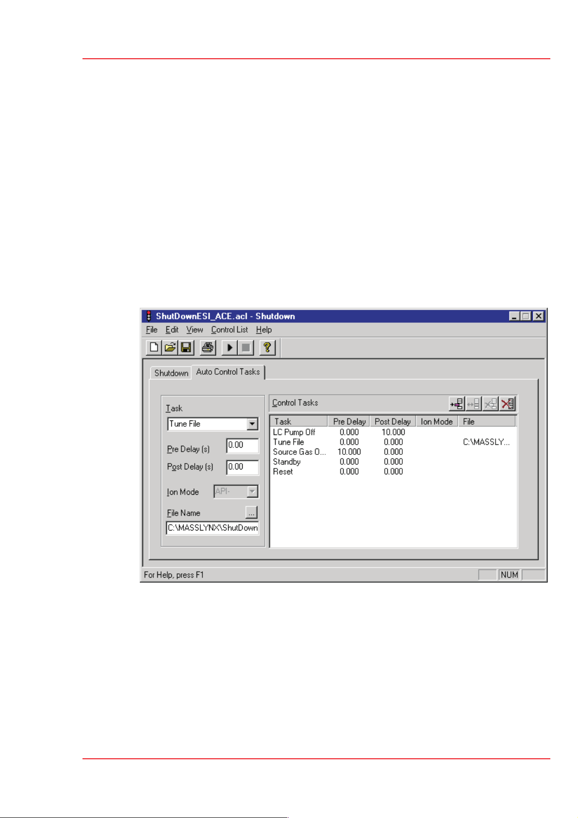
The Auto Control Tasks Page
Quattro Ultima
User's Guide
Task is a dropdown list box with all the available tasks.
Pre Delay is the length of time that elapses before the current task is performed.
Post Delay is the length of time that elapses after the current task has been
completed and before the next task is started. For example. a Post Delay of
60 seconds, in the Vent Instrument task, means that there is a delay of 60 seconds
before the next task is started, to allow the machine to vent fully.
Ion Mode is a dropdown list box with all the available ionisation modes.
Routine Procedures
Page 49

Quattro Ultima
User's Guide
File Name is selected from the browser displayed when is pressed, or is typed in
giving the full path name.
To add a task:
To insert a task:
Select a task from the dropdown task list box.
Enter the required parameters.
Press .
If this is a new task timetable the task is added to the end of the list. If a task
has been inserted into the task timetable then all subsequent tasks are added
after the inserted task. To add a task to the end of the timetable after inserting a
task, click twice with the left mouse button below the last entry in the timetable
and then add the new task.
Click on the entry in the task timetable before which the new task is to be
inserted.
Select a task from the dropdown task list box.
Enter the required parameters.
Press .
To modify a task:
Click on the entry in the task timetable.
The details for the task are displayed in the fields on the left of the screen.
Change the required parameters.
Press .
To delete a task:
Click on the entry in the task timetable.
The details for the task are displayed in the fields on the left of the screen.
Press .
To delete all tasks:
Press .
Routine Procedures
Page 50

To change the width of a column:
Position the mouse pointer on the heading between two columns until
appears.
Click the left mouse button and drag until the column is the required width.
The Shutdown Editor Toolbar
Toolbar Button Menu Equivalent Purpose
Quattro Ultima
User's Guide
File… New
File… Open
File… Save
or
File… Save As
File… Print Print a startup or shutdown file
Control List… Run List Run a startup or shutdown file
Control List… Stop List Stop a startup or shutdown file
Help… Help Topics Invoke help
Create a new startup or shutdown
file
Open an existing startup or shutdown
file
Save a startup or shutdown file
Routine Procedures
Page 51

Quattro Ultima
User's Guide
Loading Startup and Shutdown Files
To open a startup or shutdown file:
Press or select Open from the File menu.
This displays the open file dialog.
Select a data file and press Open.
Saving a Startup or Shutdown File
To save a startup or shutdown file
Press or select Save or Save As from the File menu.
If this is a new file, or if the Save As option has been selected, the Save As
dialog is displayed.
Type a name into the File Name box and press Save.
Routine Procedures
Page 52

Printing Startup and Shutdown Files
To print a startup or shutdown file:
Press , or select Print from the File menu.
This displays the print dialog.
Quattro Ultima
User's Guide
Select the printer, print range and number of copies and press OK.
Routine Procedures
Page 53

Quattro Ultima
User's Guide
Creating Startup and Shutdown Files
To create a startup or shutdown file
Press , or select New from the File menu.
Running Startup and Shutdown Files
If Startup or Shutdown is selected from the Run menu, or from the shutdown
editor control list menu, then the automatic startup and shutdown files are run.
To run a different startup or shutdown file:
Open the required file in the shutdown editor and press , or select Run List
from the shutdown editor control list menu.
To stop running this file:
Press , or select Stop List from the shutdown editor control list menu.
Routine Procedures
Page 54

Overview
Quattro Ultima
User's Guide
Tuning
Before sample data are acquired, the instrument should be tuned and, for the highest
mass accuracy, calibrated using a suitable reference compound.
•
Consult the relevant section of this manual for information concerning source
tuning procedures in the chosen mode of operation.
•
Adjust the tuning parameters in the Source and Analyser menus to optimise
peak shape and intensity at unit mass resolution.
•
Care should be taken to optimise the value of the collision energy. Note that, in
Daughter and Parent modes, Collision and Exit are interactive
parameters.
Tuning
Page 55

Quattro Ultima
User's Guide
The Tune Page
To display the tune page:
Press on the MassLynx screen MS panel.
Refer to the fold-out page at the end of this section for details of the tune page layout.
Printing Tune Information
To print a report, containing a copy of the tune peak information displayed on the
screen along with a record of each parameter setting:
Press , or select Print from the tune page File menu.
This report is not configurable by the user.
Experimental Record
Tuning parameters are stored with every data file as part of the experimental record.
The tuning parameters for a particular data file can be viewed or printed from the data
browser, see the MassLynx NT User Guide, Selecting and Viewing Data, for more
information.
Saving and Restoring Parameter Settings
Whole sets of instrument tuning parameters can be saved to disk as a named file and
then recalled at a future date.
A tune parameter file contains the latest settings for the source controls for all
supported ionisation modes not just the ionisation mode currently selected. Tune
parameter files also contain settings for the analyser, inlet set points and peak
display.
To save the current tune parameters with the existing file name:
Press , or choose Save from the tune page File menu.
Press Save.
Tuning
Page 56
To save the current tune parameters with a new file name:
Select Save As from the tune page File menu.
Enter a new file name or select an existing file from the list displayed.
Press Save.

Quattro Ultima
User's Guide
If the selected file already exists on disk a warning is displayed. Press Yes to
overwrite the existing information or No to enter a different file name.
To restore a saved set of parameters:
Press , or choose Open from the tune page File menu.
Select the required tuning parameter file, either by typing its name or by
selecting from the list displayed.
Press Open.
Tuning
Page 57

Quattro Ultima
User's Guide
Modifying the Peak Display
The tune peak display is modified using either the tune peak controls, or the mouse
directly on the display. To select peaks:
Press , or select Options, Peak Editor.
Choose the peaks to be displayed by checking the appropriate boxes.
For each active peak select the Mass, Span and Gain.
To change the function:
Select the function for the peak from the drop down list.
For MS-MS functions, Set is enabled allowing the mass of the parent, daughter,
neutral loss or neutral gain ion to be entered.
To change the tune mass:
Click and drag the mouse within the bounds of the axis to draw a “rubber band”
around the region of interest.
Release the button.
This range is redisplayed to fill the window. The mass displayed in the Mass
box is the mass at the centre of the window.
This operation can be repeated as often as required.
Pressing once displays the previous magnification range and mass, pressing
it a second time returns to the default settings.
or:
Enter a value in the Mass box for the required peak and press Return.
This becomes the default, so if the range is altered with the mouse and is
pressed twice Mass returns to this value.
or:
Tuning
Page 58
Position the cursor at the top of the peak window, just below the line showing
the gain.
When appears, click the left mouse button and drag until the required mass
is displayed in the Mass box and at the top of the window.
This becomes the default, so if the range is altered with the mouse and is
pressed twice Mass returns to this value.

Quattro Ultima
To change the span of a peak:
Press the left mouse button at one end of the region of interest and, without
releasing the button, drag the mouse horizontally to the other end.
As the mouse is dragged a “rubber band” stretches out to indicate the selected
range.
Do not go beyond the bounds of the axis.
Release the mouse button to re-display the selected range filling the current
window.
This operation can be repeated as often as required.
Pressing once displays the previous magnification range, pressing it a
second time returns to the default settings.
User's Guide
or:
Enter a value in the Span box for the required peak and press Return.
This becomes the default, so if the range is altered with the mouse and is
pressed twice Span returns to this value.
To change the gain of a peak
Double click on the line above the peak which shows the gain, to double the
gain applied to that peak.
Double click below the peak to half the gain.
or:
Press the left mouse button at one end of the region of interest and, without
releasing the button, drag the mouse vertically to the other end.
As the mouse is dragged, a “rubber band” stretches out to indicate the selected
range.
Do not go beyond the bounds of the axis.
Release the mouse button to re-display the selected range filling the current
window.
or:
Enter a value in the Gain box for the required peak and press Return.
Tuning
Page 59

Quattro Ultima
User's Guide
Changing the Display
To change the display using the mouse:
Click in the peak display area with the right mouse button to
display the pop up menu.
The display area for each peak can be individually changed, e.g.
the peak colour for peak 1 can be red and for peak 2 green etc.
Customise Plot Appearance
To change the colour of the background and traces and to change the number of traces
displayed:
Select Customise, Plot Appearance.
The Customise Plot Appearance dialog is displayed.
To change the colours on the
display:
Press Newest Trace,
Background or
Trace Fill and select a
new colour from the
dialog displayed.
To change the number of
traces:
Use to change the
number, or enter a new
value in the
Visible Traces box,
within the range 2 to 20.
If more than one trace is displayed then the older traces can be displayed in a different
shade to the new ones:
Drag the Colour Interpolation slider toward the full position. The colour of
the old traces is shown in the Trace colour sample (new->old) field.
Tuning
Page 60

Trace
Intensity
Quattro Ultima
User's Guide
From the pop-up menu:
Select the Trace, Outline option to display the peak outline only.
or:
Select the Trace, Fill option to fill the trace with the trace fill colour.
or:
Select the Trace, Min/Max option to show the minimum and maximum data
points only.
The option selected has a tick next to it.
Grid
Select either Intensity, Relative Intensity or Intensity,
Absolute Intensity as required.
Select Intensity, Normalise Data to display normalised data.
The options selected each have a tick next to them.
The options allow vertical and horizontal grid lines to be independently displayed or
hidden.
Selected options have ticks next to them. Selecting an option a second time
deselects the option.
Tuning
Page 61

Quattro Ultima
User's Guide
AutoTune
MassLynx can automatically
tune the mass spectrometer in
both APcI and electrospray
ionisation modes. AutoTune
ramps the settings for the
tuning parameters until they
are optimised to give the best
intensity, resolution and peak
shape.
To run AutoTune:
Press on the tune
page to turn on the API
gas, and select
Operate.
Choose AutoTune from the tune
page Options menu.
Press Setup to define the
AutoTune setup parameters.
There are two levels of AutoTune:
•
A full AutoTune starts from a
default set of tuning parameters.
•
A maintenance AutoTune starts from the current tuning parameters set in the
tune page and can be quicker than a full AutoTune.
A maintenance AutoTune can only be performed if the instrument is already
reasonably well tuned. If the current tuning is too poor AutoTune gives an error
and request a full AutoTune.
The Tune Mass parameter sets the mass to be tuned on. When satisfied with the
AutoTune setup parameters:
Press OK to exit.
Tuning
Page 62
Press Start.
The AutoTune status bar is updated to show the progress of AutoTune.
The following steps are performed:
•
Parameter initialisation and instrument checks
Ensuring that essential status indicators read correctly.

Quattro Ultima
User's Guide
Checking that values are defined for all the user controllable instrument
parameters and that these are passed to the data system.
Checking that readbacks for these parameters are within specified tolerances.
Beam detection
•
Focus lens tuning
•
Ion energy tuning
•
High and low mass resolution tuning
•
The final four of these steps represent the implementation of the ESP/APcI
AutoTune algorithm. This involves changing key parameters, one at a time, to
maximise the intensity of a reference peak with respect to that parameter. At
present ESP/APcI Autotuning is carried out with respect to a single user
specified reference peak.
When AutoTune has finished it displays a status dialog to say that AutoTune has been
successfully completed.
Ion Mode
Select the required ionisation mode from the Ion Mode menu. The selected mode has
a tick next to it.
Press OK to return to the tune page.
The tuning parameters determined by AutoTune are saved to the current tune
parameter file.
Tuning
Page 63

Quattro Ultima
User's Guide
Scope Parameters
Scan Time and
Inter Scan Delay control the
speed with which the tune peak
display is updated.
The tuning system behaves
more responsively if the scan
time and inter scan delay are
short.
To change the scope parameters:
Press , or choose Scope Parameters from the tune page Options menu.
Make any required changes to the settings.
Press OK.
Gas Controls
To turn a gas on or off:
Press or , or choose the required gas from the tune page Gas menu.
If the gas was previously turned off it is now turned on. A tick mark appears
next to a gas if it is turned on.
Ramp Controls
To set up a cone voltage ramp:
Choose Cone Ramp Gradient
from the tune page Ramps menu.
Two values of cone voltage are defined
at two particular masses. These values
define a gradient for the cone voltage
which is then extrapolated to cover the
full mass range.
Tuning
Page 64
Make any changes required and
press OK to exit.
To initiate the cone voltage ramp:
Press , or choose Use Cone Ramp from the tune page Ramps menu.
A tick mark appears next to the menu item if the cone voltage ramp is selected.

Quattro Ultima
User's Guide
To set up a collision energy ramp:
Choose Collision Energy Ramp Gradient from the tune page Ramps menu.
Two values of collision energy are
defined at two particular masses. These
values define a gradient for the collision
energy voltage which is then
extrapolated to cover the full mass
range.
Make any changes required and
press OK to exit.
To initiate the collision energy voltage
ramp:
Press , or choose Use Collision Energy Ramp from the tune page
Ramps menu.
Resetting the Zero Level
The zero level (or baseline) can be repositioned by pressing , or by choosing
Reinitialize from the tune page Options menu.
This command causes the instrument control system to measure the position of the
noise signal so that any baseline offset caused by the electronics or instrumentation
can be compensated for.
It is advisable to reset the zero level whenever one of the multiplier voltages is
changed.
Tuning
Page 65

Quattro Ultima
User's Guide
Controlling Readbacks
There are three options for displaying
system readbacks on the tune page:
Readbacks displayed continuously.
•
Readbacks hidden.
•
Readbacks displayed only when
•
differing from their defined values
by more than 10%.
A number of the readbacks are for diagnostic purposes only, their function being
to confirm a voltage is present. The acceptable variation between the set value
and the readback value varies depending on the particular tune parameter. If
concerned about any reading, contact your local service office for advice.
To change readback style:
Choose Readbacks from the tune page Options menu.
Select the readback style required.
Press OK.
Tuning
Page 66

Check up to four boxes
to display the peaks.
Select to
display the
tune
parameters for
that region
Create a
new tune file
Open an
existing tune file
Print current window
in portrait format
Display tune
peak information
OR
Display vacuum
information
Toggle on /
collision energ
Click on the arrow to
select the scan function
Edit window
Readback
window
Slider bar
Toolbar
Allows some
routine operations
to be performed
with a single click
Enabled for MS-MS
functions
rag the slider bar using the mouse.
APcI-ve
APcI+ve
ESI-ve
Not adjustable
Not applicable
Not applicable
ESI+ve
Tune Page
Name
Capillary +3.0 (kV) -3.0 (kV) Not applicable
Corona Not applicable 2 µA 2 µA
Cone +50 (V) -50 (V) +50 (V) -50 (V)
RF Lens 1 0 (V) 0 (V) 0 (V) 0 (V)
Aperture 0 (V) 0 (V) 0 (V) 0 (V)
RF Lens 2 +0.2 (V) -0.2 (V) +0.2 (V) -0.2 (V)
nent. When appropriate, the second column shows the term
Prefilter


Data Acquisition
Starting an Acquisition
There are two ways of starting an acquisition:
a single sample acquisition from the tune page
•
a multiple sample one from the MassLynx top level screen.
•
Starting an Acquisition from the Tune Page
The easiest way to acquire data is directly from the tune page.
Acquisitions can be started and stopped.
4
Most of the scanning parameters can be controlled.
4
Quattro Ultima
User's Guide
Inlet programs cannot be used.
6
Analog data cannot be acquired.
6
Multiple sample sequences cannot be acquired.
6
To start a single sample acquisition:
Press Acquire on the tune page, or choose Acquire from the tune page
Window menu.
The dialog
shown can be
configured to
automatically
set itself to
acquire data
using the mass
range and
function type
that is being
used for tuning
the instrument.
Make any
required
changes to the
settings.
Press Start.
Data Acquisition
Page 69

Quattro Ultima
User's Guide
Parameters
The Data File Name can be up to 128 characters. If the file already exists on disk, a
prompt is given to rename the file or to overwrite the existing one. The file is written
to the data directory of the current project.
To change the directory into which data are acquired:
The Text area is used to enter the sample description. The description can be
displayed on any output of the acquired data and has a maximum length of 74
characters. To display text on more than one line press CTRL+Return at the end of a
line.
Cancel the acquisition.
Create a new project by choosing Project Wizard, or open an existing one by
choosing Open Project, from the MassLynx top level file menu.
The type of acquisition Function used to collect the data can be any of the following:
MS
•
MS2
•
Daughter
•
•
Parent
•
Neutral Loss
•
Neutral Gain
More information is given in Function List Editor later in this chapter.
The Data Format that are collected and stored on disk can be any of the following:
•
Centroid
•
Continuum
•
MCA.
More information is given on data formats later on in this chapter.
Set Mass specifies the mass (Daughter Mass, Parent Mass etc.) that is used for the
particular function type. This control is disabled if the function selected does not
require a set mass.
Start Mass and End Mass specify the masses at which the scan starts and stops.
Start Mass must be lower than End Mass.
Run Duration is the length of the acquisition, measured in minutes.
Data Acquisition
Page 70

Scan Time specifies the duration of each scan in seconds.
Inter Scan Time specifies the time in seconds between a scan finishing and the next
one starting. During this period no data are stored.
Pressing Origin allows additional information about the sample to be analysed to be
entered into the following fields:
Submitter
•
Job
•
Task
•
Conditions
•
Multiple Samples
The MassLynx top level screen contains a sample list editor for defining multiple
samples which may be used together to perform a quantitative analysis. The list of
samples is set up using a spreadsheet style editor, which can be tailored to suit
different requirements.
Quattro Ultima
User's Guide
To start a multi-sample acquisition:
Set up a sample list (see MassLynx NT User Guide, Sample Lists for details).
Choose Start from the top level Run menu, or press .
This displays the start sample list run dialog.
Check the Acquire Sample Data, Auto Process Samples and
Auto Quantify Samples boxes as required.
Enter values in the Run From Sample and To Sample boxes.
The default is all samples in the list.
Check the Priority and/or Night Time Process boxes as required.
See the “Getting Started” chapter of the MassLynx manual for details.
Press OK.
Repeat the above procedure as required.
Sample lists are added to a queue and run sequentially unless Priority or
Night Time Process has been checked.
The sample which is currently being acquired has a next to it in the sample
list.
Data Acquisition
Page 71

Quattro Ultima
User's Guide
Process
The process controls allow processes to be run before and after the acquisition. The
Pre-Run control is used to specify the name of a process that is run before
acquisition of the files in the sample list.
The Post-Run control is used to specify the name of a process which is run after
acquisition of the files in the sample list. This could be used, for example, to switch
the instrument out of operate and to switch off various gases.
To run a process after each sample in the sample list has been acquired:
For the process to automatically operate on the data file which has just been acquired:
Format the sample list to display the Process column and enter the name of the
process to be run for each of the samples.
Leave unchecked Use Acquired File as Default on the System tab of the
MassLynx Options dialog.
The MassLynx Options dialog is accessed by choosing Options from the
MassLynx Tools menu.
Automated Analysis of Sample List
To display the quantify samples dialog:
Select Process Samples from the Quantify menu. Check the boxes required
and press OK.
The Quantify Samples dialog allows automatic processing of data files once they
have been acquired. To perform integration, calibration of standards, quantification of
samples and printing of quantification reports select the relevant check boxes. See
Quantify, MassLynx User Guide, for more detailed information about using automated
sample list analysis.
Data Acquisition
Page 72

Quattro Ultima
User's Guide
Integrate Samples integrates all the sample data files named in the peak list.
Calibrate Standards uses integration results to form quantify calibration curves.
Quantify Samples uses integration results and quantify calibration curves to
calculate compound concentrations.
Print Quantify Reports produces hard copies of the results of integration and
quantification.
Export Results to LIMS produces a text file containing the quantification results
details for use with LIMS systems. If this box is checked the LIMS Export Browse
button becomes enabled. Press Browse, select a file or enter the name of a new one
and press Save.
The Project field displays the project into which data are acquired.
To change the project into which data are acquired, the acquisition should be canceled
and a new project created by choosing Project Wizard, or an existing one opened by
choosing Open Project, from the MassLynx top level File menu.
From Sample and To Sample set the range of samples in the sample list which is
analysed.
Data Acquisition
Page 73

Quattro Ultima
User's Guide
Monitoring an Acquisition
Acquisition status is also shown on the MassLynx screen. The run time is shown on
the MS panel and the scan status, sample number and scan number are shown on the
Status bar at the bottom of the page.
The Acquisition Status Window
The acquisition status window, or scan report,
provides a scan by scan statistical report of the
progress of an acquisition.
To display the scan report dialog:
Select Acquisition Status.
This shows details of the scan currently being
acquired.
Chromatogram Real-Time Update
To view in real time the chromatogram that is
currently being acquired:
Open the data file using the MassLynx
data browser.
Press , or select Real-Time Update from the Display menu. The
chromatogram display is updated as the acquisition proceeds.
Spectrum Real-Time Update
To view in real time the spectrum that
is currently being acquired:
Open the data file using the
MassLynx data browser.
Press , or select
Real-Time Update from the
Display menu.
Data Acquisition
Page 74
Select
Enable Real-Time update.
Real-time update can also be
turned on and off via the Real-Time spectrum toolbar button.

When real-time update is on the display is continually updated with spectra from the
current acquisition. The actual information displayed is determined by selecting one of
the following radio buttons.
Latest scan displays the last acquired scan. This is the default option.
•
Average all scans updates the display with spectra formed by averaging all
•
the spectra that have so far been acquired.
Average latest scans updates the display with spectra formed by averaging
•
the last n scans acquired, where n is specified in the associated edit control.
Instrument Data Thresholds
MassLynx has several parameters that allow control over how the system
pre-processes data before it is sent to the host computer. These parameters are
contained in the instrument data thresholding dialog.
Quattro Ultima
User's Guide
Instrument data thresholding allows the user to specify the type of data to acquire and
write to disk, and the type of data to discard and not write to disk. Limiting the
amount of data stored on disk can be particularly desirable when acquiring continuum
data and doing long LC runs.
To change data thresholding:
Choose Set Instrument Threshold from the tune page Options menu.
Make the required changes to the information.
Press OK.
These new parameters are downloaded at the start of the next acquisition scan.
Data Acquisition
Page 75

Quattro Ultima
User's Guide
MaxEnt
The MaxEnt algorithm needs to measure noise accurately within a data file. For this
reason Ion Counting Threshold should be set to zero when acquiring data to be
analysed using MaxEnt.
Profile Data
The controls for profile data allow control of the amount of data collected during a
continuum data acquisition.
Baseline Level is used to lift or drop the baseline to see more or less of the noise. It
is used when Ion Counting Thresholding is disabled (set to zero) to set the
position of the baseline above zero. The baseline level is typically set to a value of 0.
It is possible to use a negative baseline. This reduces the noise seen and acts as a form
of thresholding to be applied to
counting and therefore has a less significant effect.
To see more noise use a positive value. Do not use a positive value for the baseline
level if using ion counting thresholding.
Points per Dalton can have one of three values, 4, 8 or 16.
• Selecting 8 points instead of 16 results in data files approximately half as big.
•
•
Centroid Data
Minimum centroid height sets a height below which detected peaks are ignored.
This reduces the size of acquired data files and is useful when concentrating on larger
peaks of interest.
Minimum points per peak is the minimum number of points that a continuum
peak must have to be centroided.
1
/16 amu type samples. This takes place after ion
Acquiring data at 16 points per Dalton gives the greatest possible resolution.
Acquiring data at 4 points per Dalton gives data with a smoothed appearance.
SIR Data
SIR Baseline Level sets the position of the SIR baseline above zero when
Ion Counting Threshold is not enabled (i.e. set to zero). The baseline level is
typically set to 0. Increasing the value causes the baseline to appear higher.
Data Acquisition
Page 76

Ion Counting Threshold
Ion Counting Threshold sets the intensity level below which a data point is
ignored. This threshold is applied to all acquisitions, regardless of scanning mode. It is
also the most significant of all of the data manipulation variables as it is applied to the
raw data first.
When an acquisition is started the instrument performs a ‘prescan’ with the ion beam
switched off so that the electronic noise level of the acquisition system and its
standard deviation can be measured.
The Ion Counting Threshold level entered is multiplied by the standard deviation
of the noise to determine the intensity level to be used.
Values can be set between 0 and 1000, the higher the number the more data is
•
discarded.
If a value of zero is entered the intensity level is set so that it sits in the middle
•
of the noise which means that roughly half of the noise data is acquired.
Quattro Ultima
User's Guide
A value of 10 places the threshold just above the noise so almost all of the data
•
is acquired.
If a value of 60 is entered the threshold sits well above the noise level, so very
•
little noise data is acquired.
•
A value of 30 is suitable for most data. A value of zero disables the facility.
When using an Ion Counting Threshold other than zero, both Profile Data,
Baseline Level and SIR Baseline Level should be set to zero.
Ion Counting Threshold should be set so that background noise is removed
without significantly reducing the intensity of the smallest peaks of interest.
The following table shows the effects of changing baseline noise and ion counting
threshold on background noise and low intensity peaks.
Data Acquisition
Page 77

Quattro Ultima
User's Guide
Baseline Level
Threshold
00 0 0
10 0
20 0
50 0
Ion Count
Background
Noise
Typical
Profile
Peak
Typical
Typical Intensity
Reduction
on .DAT File Size
Typical Saving
010 4%8%
0 20 11% 10%
0 40 37% 61%
0 60 66% 69%
0 250 100% 83%
Profile Data - Spike Removal
Spikes are distinguished from real data by the fact that they are very narrow and,
when compared to their immediate neighbours, very intense. Data points determined to
be spikes are removed by setting the value of this data point to the average of its
immediate neighbours.
Data Acquisition
Page 78

Quattro Ultima
Spike removal involves some additional processing while acquiring and reduces
the maximum achievable acquisition rates by approximately 30%.
To perform spike removal during an acquisition:
Check Use Spike Removal.
This is not reflected in the tune page.
Refer to the tune page intensities to assess a suitable value for the intensity
threshold below which spikes are ignored. Set Minimum Spike Intensity to
this value.
A very low intensity signal may include single ion events that can be combined
to produce significant peaks. For this type of data Minimum Spike Intensity
should be set to a suitable value such that these single ion events are not
discarded as spikes.
User's Guide
Set a suitable value for Spike Percentage Ratio.
This ratio is used to determine if a data point is a spike by comparing the data
point to its immediate neighbours. For example, with
Spike Percentage Ratio set to 33%, a data point is regarded as a spike if its
intensity is 3 times (or more) greater than both its immediate neighbours. A
setting of 20% requires an intensity ratio of 5:1 to identify a spike.
Press OK to accept any changes.
Any changes are not downloaded if Cancel is pressed.
Analog Data
Select the number of samples to acquire per second from the drop down list.
System Manager
To check the communications between
the MassLynx software and the
embedded PC:
Select Communications Status.
Data Acquisition
Page 79

Quattro Ultima
User's Guide
Stopping an Acquisition
To halt the acquisition:
From the tune page, press Stop.
From the MassLynx screen choose Stop from the Run menu, or press .
Data acquired up to this point is saved.
The Function List Editor
Introduction
The function list editor is used to set up the function(s) that the mass spectrometer
uses to scan the instrument during an acquisition. A function list can be a mixture of
different scanning techniques that can be arranged to run either sequentially or
concurrently during an acquisition.
Typical uses for mixed function acquisitions are to acquire different SIR groups over
different retention windows.
A function list is produced, saved on disk and then referenced by name when an
acquisition is started.
Data Acquisition
Page 80

Quattro Ultima
User's Guide
A simple function list is shown above, containing only one function: a centroided
mode full scan, between 500 and 1500 amu using ES+ ionisation. Immediately above
the function bar display is a time scale that shows from when the function is active,
and for how long it runs. In this case the function starts after 5 minutes and then runs
for 35 minutes, terminating after a total elapsed time of 40 minutes.
To access this dialog:
Press on the MS panel of the MassLynx screen.
A more complicated function list, with four SIR functions each running sequentially
for 5 minutes, is shown below.
The currently selected function is highlighted and enclosed in a rectangular frame. If
the display shows more than one function a new function can be selected either by
clicking with the mouse, or by using the arrow keys on the keyboard.
Data Acquisition
Page 81

Quattro Ultima
User's Guide
The Function List Editor Toolbar
The toolbar is displayed at the top of the tune window and allows some common
operations to be performed with a single click.
Create a new function list. Edit the selected function.
Open an existing function list. Delete the selected function.
Save the current function list to
disk.
Print the current window in portrait
format.
Adding a New Function
To add a new function to the list:
Click one of the toolbar buttons, or select the required function from the
Function menu.
MS2 and Neutral Gain do not have toolbar buttons and can only be created by
selection from the Function menu.
Move the selected function up the
list of functions.
Move the selected function down
the list of functions.
Create a new function of the indicated type.
Data Acquisition
Page 82
The editor for the function type selected is displayed showing default values.
Make any changes required to the parameters and press OK to add the new
function.
The function editors for each scan type is discussed in detail later on in this
chapter.

Modifying an Existing Function
To modify an existing function:
Select the function in the function list.
Press , or double click on the function.
This displays the appropriate editor for the function type and allows changes to
be made.
The function list display is updated to show any changes.
Entering a new a value in Total Run Time and pressing sets the maximum
retention time for the experiment. The ratio of the functions defined is
maintained. For example, if two functions are defined one from 0 to 5 minutes
and the other 5 to 10 minutes then a Total Run Time of 10 minutes is
displayed. If this value is changed to 20 then the first function now runs from 0
to 10 minutes and the second from 10 to 20 minutes.
Quattro Ultima
User's Guide
Copying an Existing Function
To copy an existing function:
Select the function in the function list.
Select Copy and then Paste from the Edit menu.
Modify the parameters as described above.
Removing a Function
To remove a function:
Select the function in the function list.
Press , choose Delete from the Edit menu, or press Del on the keyboard.
When asked to confirm the deletion, select Yes.
Changing the Order of Functions
Functions are displayed in ascending Start Time and End Time order and this order
cannot be changed. For functions that have the same start and end time the order in
which they are performed can be changed as follows:
Highlight the required function.
Press or repeatedly until the function is in the required position.
Data Acquisition
Page 83

Quattro Ultima
User's Guide
Setting a Solvent Delay
No data is stored during the
solvent delay period, which
means that solvent peaks that
would normally be seen eluting
on the TIC chromatogram are
no longer seen.
For APcI functions the APcI
probe temperature is set to the
value specified in the
APcI Probe Temp control for
the period of the solvent delay.
To set a solvent delay for a
function list:
Select Solvent Delay from the Options menu.
Analog Channels
If an analog channels hardware option is fitted, up to 4 channels of analog data can be
acquired, which are stored with the data acquired from the mass spectrometer. Analog
channels are typically used to collect data from external units such as UV detectors or
FID detectors. A reading is made from the external channel at the end of each scan
and stored with the data for that scan. The resolution of the chromatography for an
analog channel is therefore dependent on the scan speed used to acquire the mass
spectrometry data.
To access this dialog:
To store data for an analog channel:
Data Acquisition
Page 84
Select Analog Data from the Options menu on the Scan Functions dialog.
Check the box(es) for the channel required.
Enter a textual description for each of the selected analog channels.

This description is used on the analog chromatogram dialog as the channel
description. See “Chromatogram” in the MassLynx User’s Guide.
Enter an Offset to align the external unit with the mass spectrometer.
Press OK.
Saving and Restoring a Function List
To save a function list:
Choose Save As from the function list File menu.
Enter a new file name, or select an existing file from the list displayed.
Press Save.
If the file already exists on disk, confirmation is requested to overwrite the existing
information.
Quattro Ultima
User's Guide
Press Yes to overwrite the file, or No to select a different name.
When the editor is closed a prompt is issued to save any changed function lists.
To restore a saved function list:
Choose Open from the function list File menu.
Select the name of the function list to open, either by typing its name or by
selecting it from the displayed list.
Press Open.
Data Acquisition
Page 85

Quattro Ultima
User's Guide
Setting up a Full Scan Function
The full scan function editor, activated by pressing or by selecting
MS Scan from the Functions menu, is used to set up centroid, continuum and
MCA functions.
Mass (m/z)
Start Mass and End Mass specify the masses at which the scan starts and stops.
Start Mass must be lower than End Mass.
Start Time and End Time specify the retention time in minutes during which this
function becomes active, and data are acquired.
Cone Voltage
When Use Tune Page is checked, the cone voltage set on the tune page at the start
of the acquisition is used.
The cone voltage value cannot be altered during acquisition by typing new
values into the tune page, since the new values are not downloaded during
acquisition. This can only be done by acquiring from the tune page.
To apply a ramp to the cone voltage:
Check
Use Cone Voltage Ramp and
press CV Ramp to load the
cone ramp dialog.
The four parameters define a gradient
for the cone voltage which is then
extrapolated to cover the full mass
range of the function.
Method
Ionization Mode specifies the
ionization mode and polarity to be used during acquisition.
Data specifies the type of data to be collected and stored on disk. There are three
options:
•
•
Data Acquisition
Page 86
Centroid stores data as centroided, intensity and mass assigned peaks. Data are
stored for every scan.
Continuum. The signal received by the interface electronics is stored regularly
to give an analog intensity picture of the data being acquired. Data are not
centroided into peaks, but are stored for every scan.
Due to the fact that data are acquired to disk at all times, even when no peaks
are being acquired, continuum data acquisition places some extra burden on the

Quattro Ultima
User's Guide
acquisition system as compared to centroided acquisition. Data files tend to be
significantly larger than centroided ones and the absolute scanning speed
(amu/sec) is slower.
It is possible, however, to set a threshold below which the data are not stored.
Depending on the nature of the data acquired, this can greatly reduce these
effects. The threshold can be set so that data considered to be ‘noise’ can be
discarded, thus improving data acquisition speed and reducing data file sizes. For
more information about setting instrument data thresholds see Setting Instrument
Data Thresholds earlier in this chapter.
Multi Channel Analysis (MCA). MCA data can be thought of as ‘summed
•
continuum’, with only one intensity accumulated scan being stored for a given
experiment. As each scan is acquired, its intensity data is added to the
accumulated summed data of previous scans.
An advantage of MCA is that random noise does not accumulate as rapidly as
real data and therefore effectively averages out over a number of scans. This
emphasises the real data and improves the signal to noise ratio.
A further advantage of MCA is that because data is written to disk only at the
end of an experiment, scanning speeds can be increased and significantly less
storage space is required.
The disadvantage of MCA is that, as there is only one scan, it cannot be used for
time resolved data.
For MCA, Scans to Sum defines the number of scans to sum to create a
spectrum.
Scan Duration (secs)
Scan Time specifies the duration of each scan in seconds while Inter-Scan Delay
specifies the time in seconds between a scan finishing and the next one
starting. During this period no data are stored.
APcI Probe
Probe Temp, in degrees centigrade, is enabled when Ionization Mode is set to
APcI.
When Use Tune Page Settings is selected the APcI probe temperature set on the
tune page at the start of the acquisition is used. This control is enabled when the
ionization mode is set to APcI.
The APcI probe temperature value cannot be altered by typing new values into tune
page during the acquisition since the new values are not downloaded during the
acquisition. This can be done by acquiring from the tune page.
Data Acquisition
Page 87

Quattro Ultima
User's Guide
Setting up a SIR Function
The SIR (Selected Ion Recording) technique is typically used in situations where only
a few specific masses are to be monitored. Since most of the data acquisition time is
spent on these masses, the technique is far more sensitive than full scanning.
The SIR editor is used to enter the masses to be monitored, along with their dwell
times, spans and inter-channel delay times.
To set up a SIR function:
Press or select SIR from the functions menu.
Many of the fields are described above for the full scan editor. Only those which
differ are described below.
Channels
Up to 32 masses can be monitored. To enter a mass:
Type suitable values into the Mass, Dwell and Cone boxes.
Press Add.
Dwell specifies the length of time in seconds for which the highlighted mass is
monitored.
To modify existing settings:
Data Acquisition
Page 88

Quattro Ultima
User's Guide
Double click on a mass in the list.
This displays the values for the selected mass in the edit fields.
Change Mass, Dwell or Cone as required.
Press Change to update the values in the list.
To sort the list in order of ascending mass:
Press Sort.
Method
Inter Channel Delay specifies the time in seconds between finishing monitoring the
highlighted mass and starting monitoring the next mass in the function.
Repeats is only relevant for experiments having more than one function and specifies
the number of repeats of the function.
Span specifies a small mass window applied centrally about the highlighted mass.
During acquisition this range is scanned over the specified Dwell time. A span of zero
can be set to simply ‘sit on’ the specified mass.
Retention Window
Start and End together specify the retention time in minutes during which this
function is active.
Data Acquisition
Page 89

Quattro Ultima
User's Guide
Setting up MS-MS Scanning Functions
Many of the fields in the MS-MS editors are similar to those in the full scan editor.
Only fields which differ significantly are described below.
Mass
Daughter
This is the most commonly used MS-MS mode and is used to look at fragmentations
of a particular ion. MS1 is set to the parent mass using Daughters of, and is not
scanned.
Start and End specify the mass range to be scanned by MS2.
Data Acquisition
Page 90
The resolution of MS1 can be lowered until the peak width at the base is two
masses wide without the daughter spectrum containing any ions from the
adjacent parent masses.

Quattro Ultima
User's Guide
It is possible to select the daughter mass to be greater than the parent
(precursor) mass. In this case ions which have gained mass in the collision cell,
or are of higher mass to charge ratio, are detected. This can occur when a
multiply charged ion fragments and loses a charge.
Parent
This mode is used to look for the parent of a particular fragment.
MS2 is set to the mass of the fragment, using Parents of, and is not scanned.
Start and End specify the mass range over which MS1 is scanned. Start is normally
set just below Parents of, and End to a value above the highest expected parent
mass.
There are often several masses from which a daughter may come, so that any
one fragment is derived from a number of different peaks.
MS2
In this mode MS2 is resolving, while MS1 transmits ions over a wide mass range.
While this scanning mode can be used for acquiring data it is mostly used in the tune
window, for setting and optimising the acquisition conditions.
Neutral Loss
In this mode, the peak in a spectrum that gives the neutral loss specified in Loss of is
detected. The precursor mass is scanned in MS1, and MS2 is scanned at this mass less
the neutral loss mass. Starting masses are therefore detected on the mass scale of MS1.
Start (for MS1) should be greater than Loss of to give MS2 a valid start mass.
Neutral Gain
This is an infrequently used mode, since the mass selected by MS2 is higher than that
of MS1. It is applicable to studies where a precursor ion gains mass by ion molecule
reaction or where multiply charged ions fragment into particles with a higher m
value.
Data Acquisition
Page 91

Quattro Ultima
User's Guide
Collision Energy
This specifies the collision energy in electron volts to be used for the collision cell
during the scan.
When Use Tune Page Settings is selected the collision energy set on the tune
page is used. If it is required to adjust the setting during an acquisition then the
acquisition must be started from the tune page.
To apply a ramp to the collision energy:
The four parameters define values of
collision energy for two particular
masses. This collision energy gradient is
then extrapolated to cover the full mass
range of the function.
Check Use Collision Energy Ramp.
Press CE Ramp… to load the collision energy ramp dialog.
Data Acquisition
Page 92

Setting up a MRM Function
Multiple reaction monitoring (MRM) functions are set up in much the same way as
SIR functions, but allow a number of MS-MS transitions (fragmentations) between
MS1 and MS2 to be monitored.
Quattro Ultima
User's Guide
All fields in the MRM editor are similar to those already described.
Setting up a Survey Function
Survey scans are used to search for precursor ions. To access the dialog:
Press or select Survey Scan from the Functions menu in the
scan functions editor.
The function list editor does not add survey functions to the list if non-survey
functions are present.
Data Acquisition
Page 93

Quattro Ultima
User's Guide
Survey and MSMS Template Pages
These pages allow the parameters to be set for MS and MS-MS scanning during the
survey, and are similar to normal function editor pages.
Data Acquisition
Page 94

MS to MSMS Switching
Switch Criteria
MSMS scanning
commences:
If TIC is
•
selected,
and the TIC
of the
spectrum
rises above
the specified
Threshold.
If Intensity
•
is selected,
and the
intensity of
the largest
peak rises
above the
specified
Threshold.
Quattro Ultima
User's Guide
When a peak top
is found, no other
peaks are looked
for within the
specified
Detection Window.
Currently Number of Components is set to 1 and can not be changed. The
number of non coeluting precursors in a single run is not limited.
Precursor Selection
If Automatic is selected all valid masses satisfying selection criteria are monitored.
If Include Masses Only is selected only masses in the include list (see below) are
monitored.
If Include Masses and Automatic is selected masses on the include list are given
priority. If no precursors are found then other valid masses are monitored.
A mass is valid if it is not on the exclude list (see below), and it satisfies the
precursor selection criteria.
Data Acquisition
Page 95

Quattro Ultima
User's Guide
Detected Precursor Inclusion
Auto exclude and Always include are not currently available.
Include after time, if selected, allows a delay to be incorporated before precursors
are included.
Data
Discard uninteresting survey scans allows only the survey scans that detect
precursor ions to be stored. This saves on disk space as survey scans which contain no
relevant data are rejected.
Data Acquisition
Page 96

MSMS to MS Switching
When MSMS
functions have
been generated,
they are carried
out in parallel
until the
conditions for
switching to MS
are satisfied.
When all MSMS
functions have
stopped, the MS
survey function is
again carried out.
Quattro Ultima
User's Guide
Switch Method
If the MSMS to
MS switch
method is
Default, the
MSMS function
stops when the
MSMS to MS
switch criteria are
met.
If the MSMS to
MS switch method is After Time, the MSMS function stops when the MSMS to MS
switch criteria are met, or otherwise when the specified time has elapsed.
Switch Criteria
To define when MS scanning resumes:
Select one of the three conditions.
Set Threshold to a suitable value.
Data Acquisition
Page 97

Quattro Ultima
User's Guide
Including and Excluding Masses
Mass ranges and
individual masses
to be included or
excluded from the
MS-MS scans are
entered in the
relevant Range
boxes.
Masses on the
Exclude list are
not considered for
detection.
Ranges take the
form
massX_massY.
Masses and
ranges in a list are
comma delimited,
for example
100_200,202,236,
250_300.
Data Acquisition
Page 98
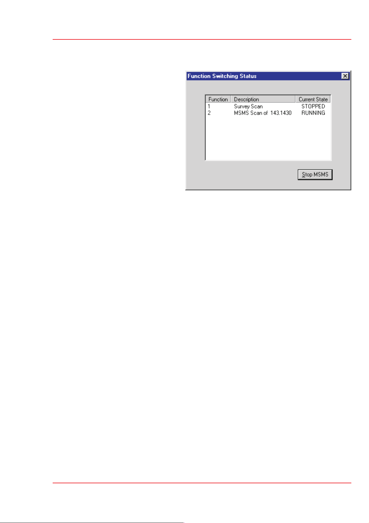
Monitoring Acquisitions
When an acquisition is
started the automatic
switching status dialog is
displayed showing the
precursors currently running.
Quattro Ultima
User's Guide
Data Acquisition
Page 99

Quattro Ultima
User's Guide
Data Acquisition
Page 100
 Loading...