

MicroM HM 525 INSTRUCTION MANUAL

HM 525
MICROTOME CRYOSTAT
HM 525
INSTRUCTION MANUAL
MICROM International GmbH
Robert-Bosch-Str. 49
D- 69190 Walldorf

HM 525
MICROM International GmbH
Robert-Bosch-Str. 49
D- 69190 Walldorf
HM 525
CERTIFICATION
MICROM International GmbH certifies that this instrument has been tested and
checked carefully. Its technical data was verified before shipment to be in
accordance with the published specifi cations.
The instrument complies with applicable international safety regulations.
WARRANTY
This MICROM product is warranted against defects in material and workmanship for
a period of 1 year. Parts which prove to be defective during the warranty period will be
repaired or replaced free of charge by MICROM International GmbH. No other
warranty is expressed or implied. Unauthorized modification or repair by third party
persons will void the warranty.
The warranty will expire in case of improper or wrong use of the instrument and in
case the warning and precautionary messages are not observed. MICROM
International GmbH is not liable for any occurring damage.
Errors and ommissions excepted. Subject to amendment and improvement without
further notice.
This instruction manual will be supplied together with each instrument. Further
copies can be ordered at the nearest MICROM sales office by giving the serial
number of the instrument, the number of the instruction manual and the date of
issue.
This instruction manual is available in the following languages:
Cat. No.
German: 387778
English: 387779
French: 387780
Spanish: 387781
MICROM International GmbH
Robert-Bosch-Str. 49
D- 69190 Walldorf

HM 525
MICROM International GmbH
Robert-Bosch-Str. 49
D- 69190 Walldorf
HM 525
INTENDED USE
Dear Customer,
Before putting the instrument into operation, please read these operating
instructions carefully to familiarize yourself with its proper operation and
functions.
The MICROM cryostat HM 525 is a highly efficient cryostat for sectioning
techniques in routine and research.
Only skilled or specially trained personnel must operate the microtome
cryostat, i.e. placing the specimen onto a chuck, sectioning and transferring
sections onto a slide. The listed and marked safety measures as well as the
regulations and hygiene measures of your respective lab must strictly be
observed.
MICROM Ser. No. :..................................................
Please check the MICROM Ser. No. on the type plate, which is placed on the
rear side of your instrument and enter this number here. This way, questions
and service can be handled faster.
Instruction Manual No. 387779
Issued on July 13, 2004
MICROM International GmbH
Robert-Bosch-Strasse 49
D-69190 Walldorf
Telefon: (06227) 836-0
Telefax: (06227) 836-111
MICROM International GmbH
Robert-Bosch-Str. 49
D- 69190 Walldorf

HM 525
Intended Use
Table of Contents
EC Certificate of Conformity
Safe ty Precautions
PART 1 INTRODUCTION
1-1 Description of the HM 525
1-2 Technical data HM 525
PART 2 OPERATING INSTRUCTIONS
2-1 Setting up the cryostat
2-2 Initial turn-on
2-3 Basic operational rules
2-3-1 Actual and set value of the chamber temperature
2-3-2 Defrosting the evaporator
2-3-3 Interrupting a defrosting cycle
2-3-4 Emptying the defrosting liquid
2-3-5 Illumination of the cryo chamber
2-3-6 Freezing on a specimen
2-3-8 Specimen orientation with zero positioning
2-3-9 Handwheel lock
2-4 Cutting process
2-4-1 Cutting movement and retraction
2-4-2 Setting section thickness and trimming thickness
2-5 Feed
2-5-1 Specimen coarse feed
2-5-2 Memory function
2-5-3 Trimming and first cuts
2-5-4 Fine feed
2-6 Indication of cutting processes
2-6-1 Section counter
2-6-2 Sum of section thicknesses
2-6-3 Remaining travel to front end position
2-6-4 Setting the real time
2-7 Knife carriers
2-7-1 Standard knife carrier
2-7-2 Disposable blade carrier
2-7-3 Disposable blade carrier EC 70
MICROM International GmbH
Robert-Bosch-Str. 49
D- 69190 Walldorf

HM 525
2-8 Error code indication
2-8-1 Definition of the error codes
2-9 Accessories
2-9-1 Standard equipment
2-9-2 Additional equipment
PART 3 THEORY OF OPERATION
3-1 Microtome cooling, defrost cycle
3-2 Cutting movement
3-3 Specimen coarse feed and trimming stages
PART 4 WORKING WITH THE CRYOSTAT
4-1 Preparations on the microtome and inside the cooling chamber
4-2 Freezing on the specimen
4-3 Orientation and trimming of specimens
4-4 Temperature list for cryo sectioning
4-5 Sectioning and taking off sections
4-6 How to avoid malfunctions
4-6-1 Possible sources of errors – cause and removal
PART 5 MAINTENANCE AND CARE OF THE CRYOSTAT
5-1 Shutting-off for cleaning
5-2 Removing the microtome
5-3 Cleaning and care of the microtome
5-4 Cleaning the cooling lamella
part 6conditions for the transportation of the instrument
6-1 Taking back the instrument for repair or routine maintenance
6-2 Disposal of the instrument after final shutdown
MICROM International GmbH
Robert-Bosch-Str. 49
D- 69190 Walldorf
HM 525
EC Certificate of Conformity
Name and address of MICROM International GmbH
the manufacturer: Robert-Bosch-Straße 49
D-69190 Walldorf
Product designation: Microtome Cryostat
Type reference: HM 525
Notification to Competent Authorities:
These medical device have been registered with the German authority as “Microtomes” under
the EDMA-classification code: 23-06-02
The designated product complies with the laid down regulation:
DIRECTIVE 98/79/EC OF THE EUROPEAN PARLIAMENT AND OF THE COUNCIL
of 27 October 1998
on in vitro diagnostic medical devices
The designated product complies with the EC regulations by strictly observing the following
norms:
DIN EN ISO 14971:2001-03
Medical devices - Application of risk management to medical devices (ISO 14971:2000).
DIN EN 61010-1:2002-08
Safety requirements for electrical equipment for measurement, control and laboratory use - Part 1:
General requirements (IEC 61010-1:2001).
DIN EN 61010-2-101:2003-09
Safety requirements for electrical equipment for measurement, control and laboratory use - Part 2-101:
Particular requirements for In -Vitro-Diagnostic-(IVD)-Medical instruments.
DIN EN 61326:2002-03
Electrical equipment for measurement, control and laboratory use - EMC requirements (IEC 613261:1997 + A1:1998 + A2:2000); German version EN 61326:1997 + A1:1998 + A2:2001
DIN EN ISO 9001:2000
Quality management systems - Requirements (ISO 9001:2000)
Hans Heid Walldorf, 15 June 2004
Managing Director
MICROM International GmbH
Robert-Bosch-Str. 49
D- 69190 Walldorf
HM 525
SAFETY PRECAUTIONS
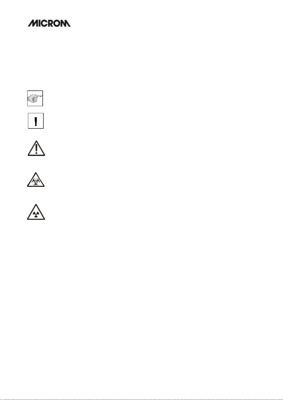
WARNING SIGNALS AND SYMBOLS
The installation and routine use of the HM 525 is easy and safe if the instructions in this manual are being
observed.
Biohazard:
Warning of biological danger.
Note:
Special instructions regarding operation of the instrument.
Warning:
Special prec autionary measures to prevent damage to equipment. For a long lifetime of the
equipment, please observe these instructions carefully.
Caution – general danger spot:
The instruction manual must strictly be observed whenever this symbol is visible on the instrument.
Radioactivity:
Warning of radioactive danger.
MICROM International GmbH
Robert-Bosch-Str. 49
D- 69190 Walldorf
HM 525
SAFETY PRECAUTIONS
C A U T I O N !
The operator's safety is affected, when the instrument is not operated in accordance
with this instruction manual.
Please observe the following general precautions during operation of this
instrument. Failure to comply with these precautions violates safety standards and
the intended use of the instrument. MICROM International GmbH is not liable for
misuse of the instruments and failure to comply with basic safety requirements.
INSTRUMENT GROUNDING
To avoid injury from electrical current, the instrument must be connected with the protective earth. The
instrument is equipped with a three wire ground plug. The power outlet must be connected to the protective
earth and must meet the International Electrotechnical Commission (IEC) regulations.
CAUTION: MAINS VOLTAGE
Never remove instrument covers during operation. Component replacements as well as adjustments must only
be made by trained service personnel. Unplug the unit before removing or opening the covers.
DANGER IN EXPLOSIVE ENVIRONMENT
The instrument must not be operated in the presence of flammable gases.
HAZARD OF FROSTBITE
Avoid permanent touching of metal parts inside the cryostat microtome chamber as frostbite may occur at
unprotected hands and arms.
HAZARD OF RADIOACTIVE RADIATION
When working with radioactive specimens observe all applicable radiation safety procedures. When working
with radioactive contaminated material, appropriate safety and disinfection measures must be carried out.
According to the rules and regulations concerning the handling of radioactive contaminated material of the
respective laboratory, safety clothing (e.g. particle mask, gloves, protective shoe covers) must be worn.
Radioactive contaminated waste must be disposed of according to the respective regulations.
MICROM International GmbH
Robert-Bosch-Str. 49
D- 69190 Walldorf
HM 525
HAZARD OF INFECTION
Use the appropriate safety and disinfection measures when working with infectious specimens.
According to the rules and regulations concerning the handling of infectious/radioactive contaminated material
of the respective laboratory, safety clothing (e.g. particle mask, gloves, protective shoe covers) must be worn.
HAZARD OF BIOLOGICAL DANGER
Specimens used during the intended operation of the instrument might potentially be infectious. For this
reason, it is recommended to observe the general laboratory regulations concerning protection against danger
of infection.
Information on decontamination media, their use, dilution and effective range of application can be read in the
Laboratory Biosafety Manual : 1984 of the World Health Organization.
HAZARD OF MALFUNCTION
To avoid the hazard of malfunction of an instrument, it must only be operated in a controlled electromagnetic
environment. This means, that transmitters suc h as mobile phones must not be operated in their close vicinity.
In case of malfunctions and/or service work, please turn off the instrument and contact your local dealer.
CARE IN USING MICROTOME KNIFE
To diminish the danger of being injured by the knife or blade, use the knife guard when adjusting specimen and
knife. If possible, the specimen should be clamped in before the knife is inserted into the knife holder. Before
changing the knife holder, always remove blade or knife! Unused knives should always be kept in a knife case.
Never place the knife with the cutting edge upwards. Never try to catch a dropping knife!! Never check the
sharpness of the cutting edge with your fingers. The cutting edge is extremely sharp!
WASTE DISPOSAL
All debris, waste, defrosting liquid as well as infectious and radioactive contaminated material from operation
must be disposed of in accordance with the respective regulations of the lab. Disinfection and cleaning liquids
as well as section waste must be disposed of according to the respective regulations for special waste!
MICROM International GmbH
Robert-Bosch-Str. 49
D- 69190 Walldorf
HM 525
MICROM International GmbH
Robert-Bosch-Str. 49
D- 69190 Walldorf
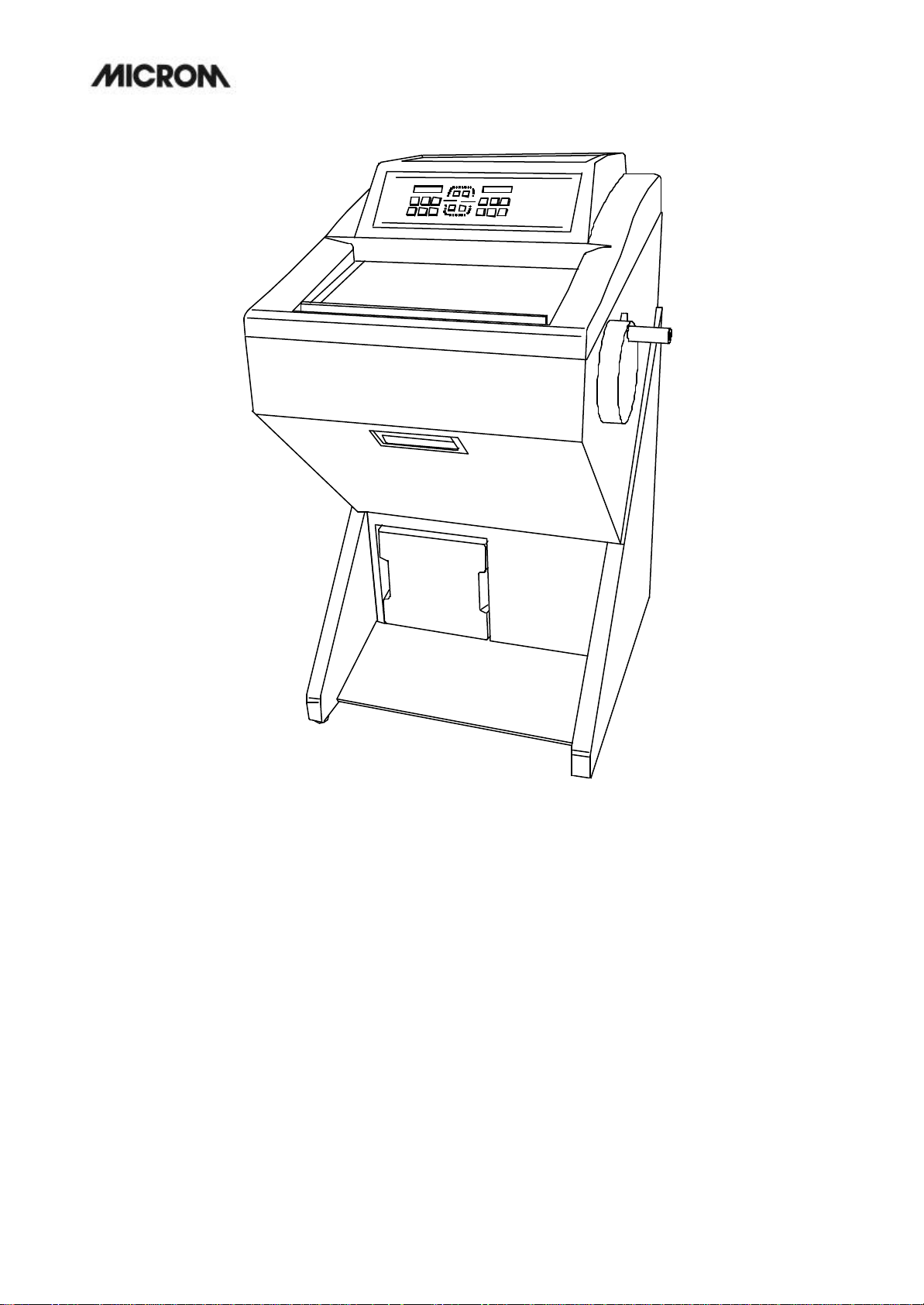
Fig. 1

HM 525
1 INTRODUCTION
1-1 DESCRIPTION OF THE HM 525
Open top cryostat. Stainless steel cooling
chamber. Chamber temperature regulation variable
from +5°C down to –35°C.
Graphic LED-display of set and actual
temperatures, electronic control with user-oriented
touchpad keyboard, battery-buffered memory and
self-diagnostic system.
Automatic defrosting and in addition a manual
defrost cycle which can be activated when needed.
Defrost interrupt on keystroke request.
Integrated fast freezing device down to max.
–60°C via Peltier element.
Sliding window with heater. Integrated fluorescent
lamp for cryo-chamber. Brush shelf and storage
space inside the cryo chamber. Large, flat storage
space on top of the housing with integrated storage
space for marked slides.
Rotary Microtome with backlash and maintenancefree cross roller bearings in stainless steel. Electromechanical feed system.
Section thickness setting from 1 to 20 microns;
up to 10 µm in 1 µm -increments,
up to 20 µm in 2 µm -increments,
Trimming thickness setting from 10 to 500 microns;
up to 100 µm in 10 µm -increments,
up to 300 µm in 50 µm increments and
up to 500 µm in 100 µm -increments.
Specimen retraction during the return stroke with
optical indication. Horizontal feed range 28 mm.
Vertical cutting stroke 60 mm.
Max. specimen size 70 x 55 mm.
Motorized coarse feed in two directions.
Limit indication and automated switch off at front
and rear limits of horizontal travel.
Section counter and indication of sum of section
thicknesses with reset-button. Indication of
remaining travel.
Mechanical handwheel brake in the lower reversal
point of the specimen orientation.
Fine orientation of specimen 8° universally in x/yaxis with zero device. Rotatable on Z-axis, 360°.
Basic outfit with 3 x 30 mm chucks, 1 x 40 mm
chuck, 118 ml MICROM freezing medium, 100 ml
cryostat oil, brush shelf and section waste tray,
consisting of two parts.
MICROM International GmbH
Robert-Bosch-Str. 49
D- 69190 Walldorf

HM 525
1-2 TECHNICAL DATA HM 525
Chamber temperature control: .........................................................................+5°C to -35°C
Fast freezing station via Peltier element
depending on the chamber temperature: ..................................................down to max. -60°C
Defrosting: automatic defrosting, adjustable.............. with temperature control
manual immediate defrosting
Microtome: Section thickness range: ........................................... 1 - 500 µm
Fine section thickness range: ...................................... 1 - 20 µm
Resolution: ................................................... 1 µm for 1 - 10 µm
................................................................... 2 µm for 10 - 20 µm
Trimming thickness range:........................................ 10 - 500 µm
Resolution:............................................... 10 µm for 10 - 100 µm
..............................................................50 µm for 100 - 300 µm
............................................................ 100 µm for 300 - 500 µm
Specimen retraction during return travel..............................40 µm
Vertical specimen stroke ............................................... 60 mm
Horizontal specimen movement........................................28 mm
Read-outs: Five-digit LED-display: section thicknesses, section counter, sum of
section thicknesses, remaining travel to front end position and
chamber temperature
Coarse feed: .............................. motorized, graduated, single and continuous
Size of chucks: ................................................................................30, 40 mm
........................................................ special sizes upon request
Specimen orientation: x - and y - axes: ...................... universal 8° with zero positioning
z - axis: .................................................................. up to 360°
Cooling chamber illumination
Sliding window
Cutting drive: ............................................................ manually via handwheel
Cutting area: ....................................... horizontal specimen movement 28 mm
.................................................vertical specimen stroke 60 mm
All temperatures refer to an ambient temperature of +20°C!
Cont'd on page -2-
MICROM International GmbH
Robert-Bosch-Str. 49
D- 69190 Walldorf
2

HM 525
1-2 TECHNICAL DATA HM 525
Handwheel brake: ...............................................................................mechanical
Transportation and storage conditions
Storage temperature range: -20°C up to +50°C
Operating conditions: .......................+5°C up to +35°C (at a max. rel. humidity of 60%)
...................................................... altitude up to 2000 m M.S.L.
.....................................................................for indoor use only
........................................ Floor loading requirements: 230 kg/m2
Power requirements: ....................................................... 100 V/50 Hz, 12 A, +/-10%
........................................................ 100 V/60 Hz, 12 A, +/-10%
........................................................ 115 V/60 Hz, 12 A, +/-10%
................................................. 220...230 V/50 Hz, 6 A, +/-10%
..........................................................220 V/60 Hz, 6 A, +/-10%
..........................................................240 V/50 Hz, 6 A, +/-10%
Internal protection
Primary circuits:
Transformer: ..................................................................T5.0AH, 100...115 V
..................................................................T2.5AH, 220...240 V
Illumination: ..................................................................T0,8AH, 100...115 V
..................................................................T0,4AH, 220...240 V
Secondary circuits:
Window heating: .................................................................................... T2,5AH
CPU: ........................................................................11 VAC/T0.5AH
Panel: ........................................................................11 VAC/T0.5AH
Stepping motor/valve: ........................................................................24 VAC/T2.5AH
Fast freezing station: .................................................................... 2.3/8 VAC/T8.0AH
Pollution degree: ............................................................................................. 2
Overvoltage category: ..............................................................................................II
Sound pressure: .................................................................................. 45 dB(A)
............................. measured with 1 m distance to the instrument
Fluids and gases: ................................................................cooling agent: R404a,
............................................... filling amount: 100...120 V: 250 g
.................................................................... 220...240 V: 230 g
Dimensions: ... Wide (w/o handwheel): 640 mm, deep: 760 mm, high: 1200 mm
Weight: ................................................ 143 kg (depending on the model)
All temperatures refer to an ambient temperature of +20°C!
page -2-
MICROM International GmbH
Robert-Bosch-Str. 49
D- 69190 Walldorf
3
HM 525
10 9
35
13
15
18
4 2 1 11
17
COUNT
SUM
TRAVEL
8
7 6
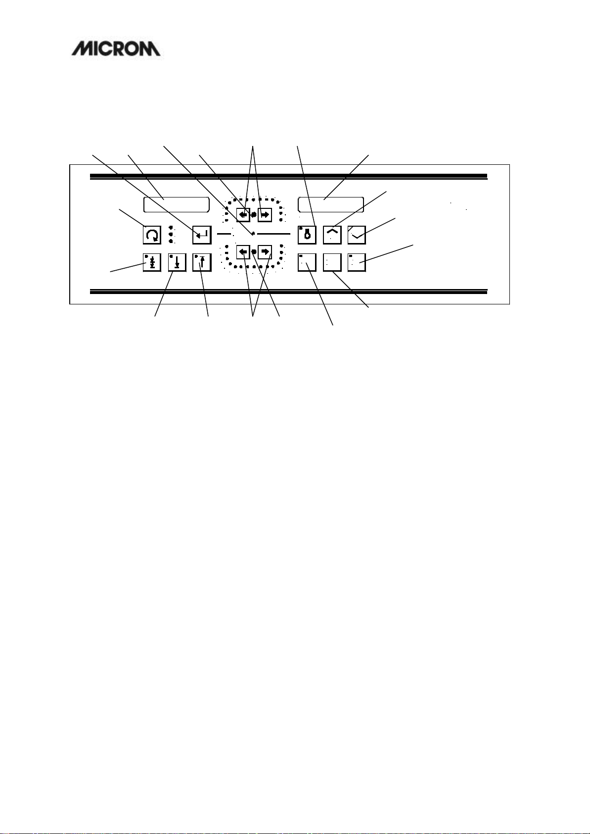
1 = LED retraction
2 = Section thickness setting
3 = Trimming thickness setting
4 = LED fine feed
5 = LED trim feed
6 = Coarse feed, backwards
7 = Coarse feed, forwards
8 = Trim button
9 = Scroll button
7 8 9 10 12
6
5
4
3
2
SECTION THICKNESS µm
RETRACT
TRIM THICKNESS µm
10
20
30
40
50
60 70 80 100 150
14
16
18
20
22
500
400
300
250
200
CHAMBER TEMPERATURE ° C
UP
DEFR
MEMO
TIME
P
DOWN
INTER
RUPT
16
MICROM
14
12
10 = Display, left
11 = Reset button
12 = Memory button
13 = Setting defrost time
14 = Interruption defrosting cycle
15 = Down button and activation of Peltier element
16 = Up button
17 = Chamber illumination
18 = Display, right
HM 520
Fig. 2
MICROM International GmbH
Robert-Bosch-Str. 49
D- 69190 Walldorf
4
HM 525
3
1
2 OPERATING INSTRUCTIONS
2-1 SETTING UP THE CRYOSTAT
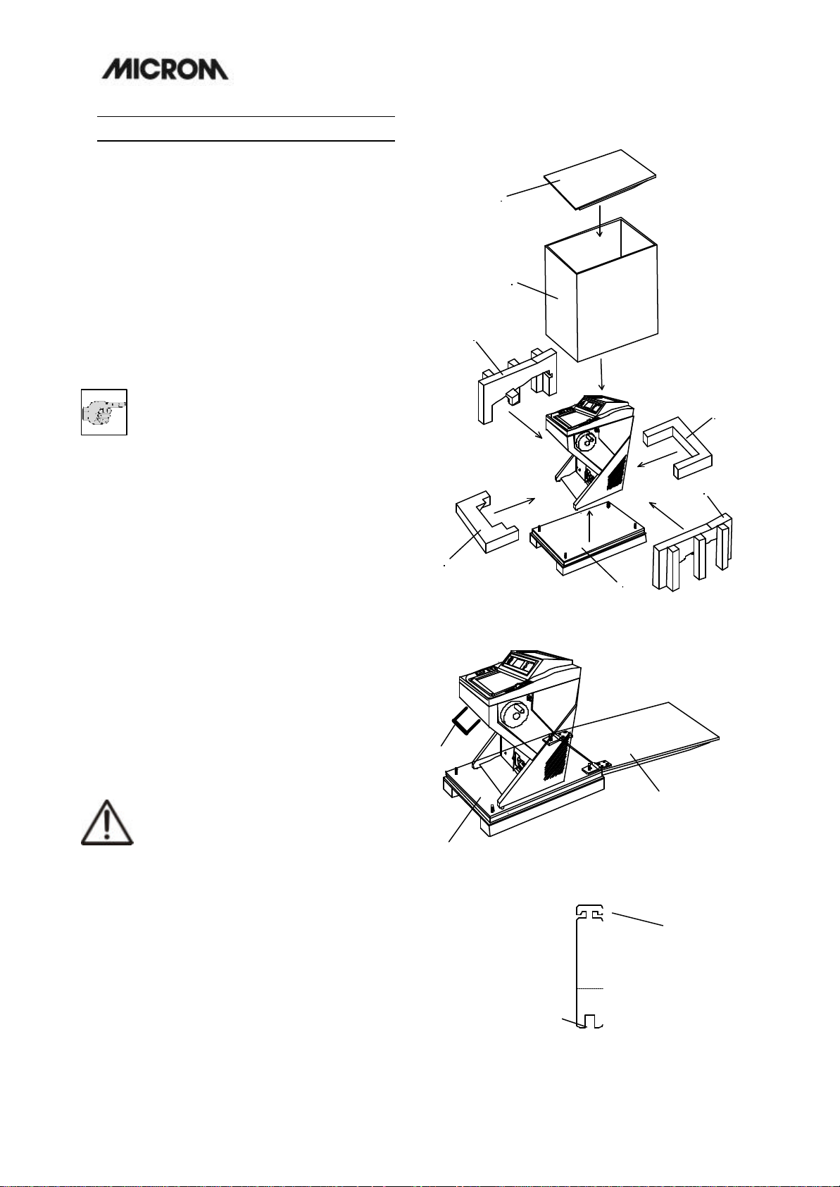
Unpacking the instrument:
??Cut through the three packing straps and
remove the packing.
??Remove the upper wooden cover (fig. 3.1).
??The hinges of the upper wooden cover are
secured with tape.
??Remove this tape.
??Lift the packing (fig. 3.2) over the instrument.
??Remove the upper and lower supporting foams
(fig. 3. 3, 3.4, 3.5, 3.6) from the cryostat.
Note:
The upper wooden cover now serves as
an incline (fig. 3a.1) on which the
cryostat can be moved from the palett
to the floor by using the handle (fig. 3a.2)
??The hinges of the upper wooden cover (fig. 3.1)
are inserted into the screws of the bottom
plate (fig. 3a.3). The correct side for this is
marked with arrows.
??The tool (fig. 3b.2, size 30) for the height
adjustment of the setting feet of the cryostat is
packed together with the accessories of the
cryostat (separate carton on the foot rest of
the cryostat).
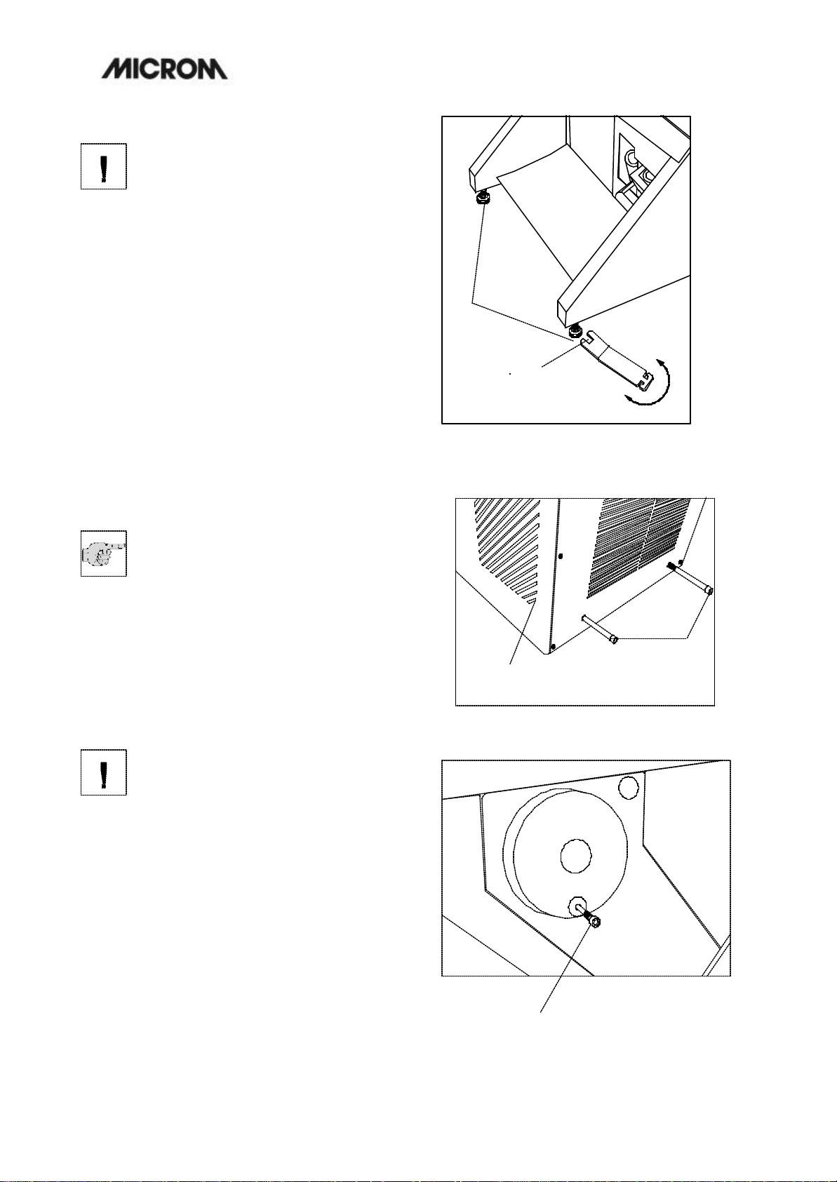
??Turn the setting feet completely upwards via
this tool so that the cryostat stands with its
rollers on the bottom plate (fig. 3a.3).
??Via the handle (fig. 3a.2) roll the cryostat from
the bottom plate (fig. 3a.3) over the wooden
cover (fig. 3a.1). In doing so, the rear side of
the instrument must show to the incline (fig.
3a.1).
Caution:
The instrument is very heavy. While the
instrument rolls down on the incline, it
must be guaranteed that the instrument
does not move in an uncontrolled way.
??Now the cryostat can be rolled to its site of
installation.
??For possible return shipments, please keep
the packing.
1
2
3
HM550MVD
0
1
2
3
6
7
5
4
Fig. 3
2
3
HM550M
0
1
Fig. 3a
1
2
Fig. 3b
MICROM International GmbH
Robert-Bosch-Str. 49
D- 69190 Walldorf
5

HM 525
MICROM International GmbH
Robert-Bosch-Str. 49
D- 69190 Walldorf
HM 525
Warning:
The instrument must only be moved in
standing or slightly tilted (approx. 30°)
position.
Choose installation site that
??enough ventilation for the cooling system is
guaranteed.
??the distance between wall and rear panel is
approx. 15 cm. For this, install the distance
bolts (fig. 4a.1).
??the suction areas (fig. 4a.2) on either side are
kept free.
??the mains switch for separating the instrument
from the power supply is accessible any time.
Moreover, the installation site must be free
from:
??draught by open doors or by air conditioning
systems.
??direct exposure to sunlight into the cooling
chamber.
Note:
Both measures reduce the formation of
frost and therefore result in more
favourable work conditions. A high air
moisture as well as high ambient temperatures
reduce the maximum performance of the
instrument.
?? To fix the complete unit, tighten the screws
(fig. 4.1) by using the attached tool.
?? Install the separate packed handwheel
handle.
Warning:
Instead of the handwheel handle, a
transportation screw (fig. 4b.1) is
inserted into the handwheel. This way,
the handwheel is tightly and securely connected
with the housing of the cryostat. It is
absolutely necessary to remove this
transportation screw before the initial turnon!
?? Loosen the transportation screw (fig. 4b.1)
via the Allan key, size 6.
?? Now fix the separately packed handwheel
handle on the handwheel with the attached
screw by means of the Allan key.
MICROM International GmbH
Robert-Bosch-Str. 49
D- 69190 Walldorf
1
SW13
Fig. 4
1
2
Fig. 4a
Fig. 4b
1
HM 525
1
2
2-2 INITIAL TURN-ON
Note:
The kind of the used examination
materials and all special conditions for
their processing, pre-treatment and, if
necessary, storage as well as instrument
controls for correct and safe operation is in the
responsibility of the operator.
The operator is also responsible for special
equipment and materials and/or reagents for the
operation of the instrument.
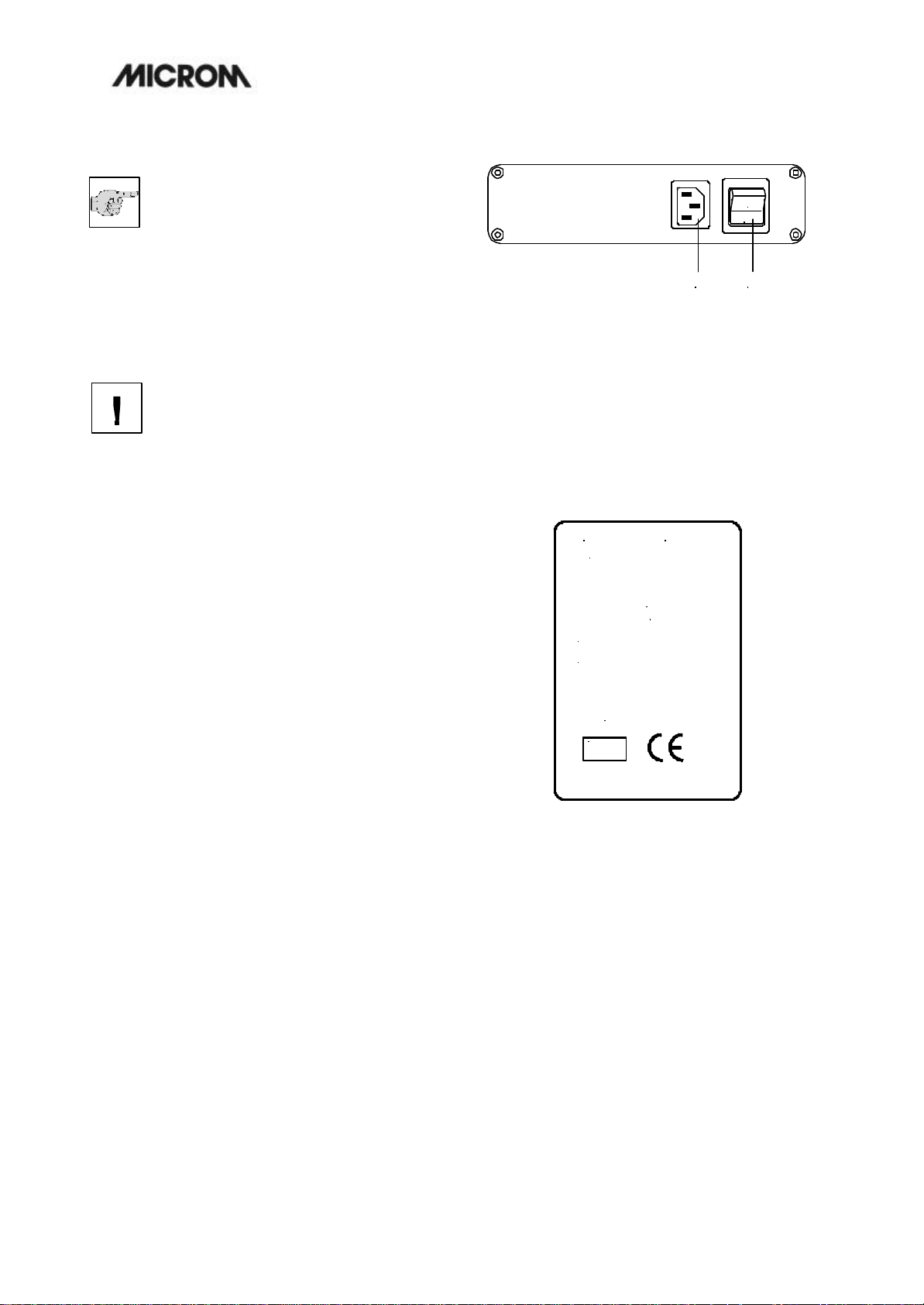
Warning:
Before turning on the instrument for the
first time, please check if the power
requirements indicated on the type
plate (fig. 6) correspond to the power supply
voltage being used.
??No other instruments should be connected to
the circuit used for the cryostat, as the
compressor needs high surge currents when
started.
??Do not use multi-socket power outlets with
small wire sizes for the supply of the
instrument.
??We recommend to immediately install all
accessories belonging into the cryo chamber,
e.g. blade carrier.
??The instruction manual of the instrument can
be found in the separate carton which is
placed on the foot part of the cryostat.
??Connect the power line of the instrument to
the power outlet.
??Turn on the power switch (fig. 5.1) on the rear
side of the instrument.
??Close the heated sliding window and cool
down the instrument.
The cooling phase will take several hours
depending on the set chamber temperature.
1 = Power switch
2 = Mains plug
MICROM
Chamber
Refr.: R 404a
Amount: _ _ _ _ _kg
Max. Press.: 1900kPa
69190 Walldorf, Germany
Type HM 520_
Type HM 525
Ser. No. _ _ _ _
Cat. No. _ _ _ _ _ _
_ _A /_ _ _V _ _ Hz
Made in Germany
GmbH
I V D
I
0
Fig. 5
Fig. 6
MICROM International GmbH
Robert-Bosch-Str. 49
D- 69190 Walldorf
HM 525
2-3 BASIC OPERATIONAL RULES
After having turned on the instrument, the two
displays show the set chamber temperature as
well as the number of sections, the section
thickness sum as well as the remaining travel to
the front end position. Section thicknesses are
indicated via LEDs.
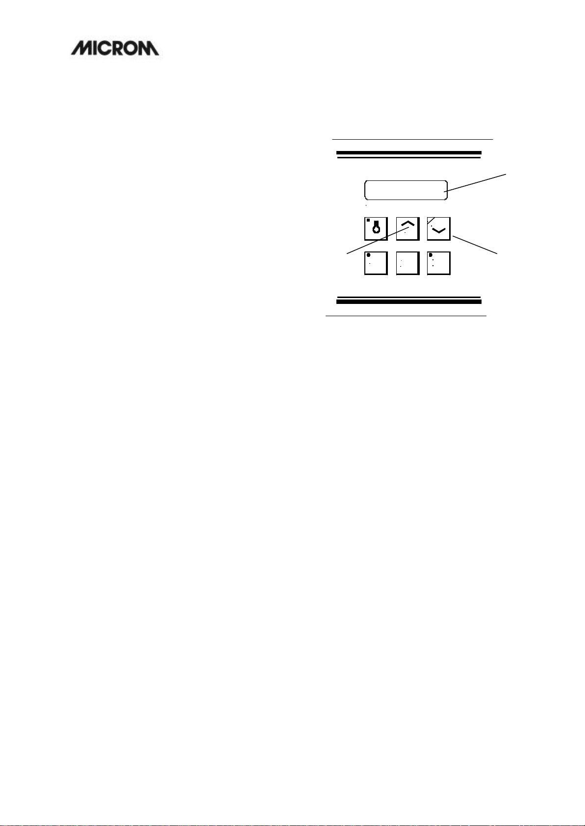
2-3-1 ACTUAL AND SET VALUE OF
THE TEMPERATURE
The cooling of the microtome chamber can be
controlled by the corresponding part of the
operating controls. The actual temperature of
the microtome chamber is shown in °C on the
digital display (fig. 7.1). Briefly press the UP - or
DOWN-button (fig. 7.2 or 7.3), the set value of
the temperature in the microtome chamber is
shown for approx. 2 sec. Afterwards, the display
shows again the actual value of the temperature
of the microtome chamber. To change the set
value, press permanently the UP-button (fig.
7.2) or DOWN-button (fig. 7.3). The UP-button
leads to higher, the DOWN-button to lower
temperatures.
The valid range of the set value goes from +5°C
down to -35°C. If the UP -button is used beyond
the limit of +5°C, the display shows
" - - -" and the temperature control is turned off.
Using the DOWN-button the cooling system is
turned on again.
CHAMBER TEMPERATURE ° C
P
DOWN
UP
2 3
MEMO
DEFR
TIME
INTER
RUPT
1
Fig. 7
MICROM International GmbH
Robert-Bosch-Str. 49
D- 69190 Walldorf
 Loading...