

Page 1
#86908
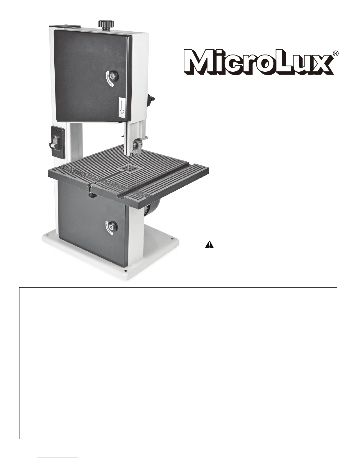
7-3/4" Band Saw
User's Manual
WARNING: To reduce the risk
of injury, the user must read and
understand the user's manual
before using this product.
LIMITED WARRANTY
Micro-Mark guarantees this product to be free of manufacturing
defects for a period of 90 days from date of shipment, regardless
of the amount of time the product has been used and/or stored.
The product, or parts thereof, will be repaired or replaced (at our
option) and shipped back to you free of charge if the following
conditions have been met:
• the product is shipped back to us within the warranty period,
• incoming transportation charges have been pre-paid,
• proof of purchase has been provided, and
• our Service Department determines that the problem was
caused by a defect in material and/or workmanship.
Please return to Micro-Mark Product Service Dept. at the address
below with a note explaining the problem.
For products returned after the warranty period, our regular repair
charges shall apply. Please include your telephone number so
we may advise you of the repair estimate. Any product returned
to the purchaser without repair work being performed shall be
shipped C.O.D. for the return transportation charges.
This warranty does not cover damages resulting from improper
assembly, adjustment or maintenance, accident, alterations,
normal wear, abuse or misuse, and does not apply where
products are used commercially. The warranty shall also not
apply when the product has been used for purposes beyond
those for which it was designed or unreasonable for its size.
Micro-Mark makes no other warranty of any kind whatever,
expressed or implied, and all implied warranties of merchantability
and fitness for a particular purpose which exceed the above
mentioned obligation are hereby disclaimed by Micro-Mark and
excluded from this warranty.
This warranty gives you specific legal rights and you may also
have other rights which vary from state to state. The obligation
of the warrantor is solely to repair or replace the products.
The warrantor is not liable for any incidental or consequential
damages due to such defect. Some states do not allow the
exclusion or limitations of incidental or consequential damages,
so the above limitations or exclusion may not apply to you.
If you have any questions, please contact our Product Service
Department by email: [email protected]
Product Service Department
340 Snyder Avenue
Berkeley Heights, NJ 07922
MM041117
Page 2

GENERAL SAFETY RULES
WARNING:
READ ALL INSTRUCTIONS. Failure to follow all instructions listed below may result in electric
shock, re and/or serious personal injury.
1. KNOW YOUR POWER TOOL. Read this manual carefully. Learn the applications and limitations,
as well as the specic potential hazards related to this tool.
2. GUARD AGAINST ELECTRICAL SHOCK by preventing body contact with grounded surfaces. For
example: pipes, radiators, ranges, refrigerator enclosures.
3. KEEP GUARDS IN PLACE and in good working order.
4. REMOVE ADJUSTING KEYS AND WRENCHES. Make a habit of checking to see that keys and
adjusting wrenches are removed from tool before turning it on.
5. KEEP WORK AREA CLEAN. DO NOT leave tools or pieces of wood on the saw while it is in
operation.
6. DO NOT USE IN DANGEROUS ENVIRONMENTS. Do not use power tools near gasoline or other
ammable liquids, in damp or wet locations, or expose them to rain.Keep the work area well-lit.
7. KEEP CHILDREN AND VISITORS AWAY. All visitors should wear safety glasses and be kept a
safe distance from the work area.
8. MAKE WORKSHOP CHILDPROOF with padlocks, master switches, or by removing starter keys.
9. DON’T FORCE THE TOOL. It will do the job better and safer at the feed rate for which it was
designed.
10. USE THE RIGHT TOOL. Do not force the tool or attachment to do a job for which it was not
designed.
11. USE THE PROPER EXTENSION CORD. Make sure your extension cord is in good condition.
Use only a cord heavy enough to carry the current your tool will draw. An undersized cord will cause a
drop in line voltage resulting in loss of power and overheating. A wire gauge size (A.W.G.) of at least
16 is recommended for an extension cord 25 feet or less in length. If in doubt, use the next heavier
gauge. The smaller the gauge number, the heavier the cord.
12. DRESS PROPERLY. Do not wear loose clothing, gloves, neckties, or jewelry. They can get
caught and draw you into moving parts. Wear protective hair covering to contain long hair.
13. ALWAYS WEAR SAFETY GLASSES WITH SIDE SHIELDS. Everyday eyeglasses are NOT
safety glasses.
14. DON’T OVERREACH. Keep proper footing and balance at all times.
15. MAINTAIN TOOLS WITH CARE. Keep tools sharp and clean for better and safer performance.
Follow instructions for lubricating and changing accessories.
16. DISCONNECT TOOLS. When not in use, before servicing, or when changing attachments,
blades, bits,cutters, etc., all tools should be disconnected from the power source.
17. AVOID ACCIDENTAL STARTING. Be sure switch is set to OFF when plugging in any power tool.
Page 3
GENERAL SAFETY RULES, CONTINUED
18. CHECK FOR DAMAGED PARTS. Before using the tool, visually inspect for any part that is
damaged. Damaged parts must be properly repaired or replaced by an authorized service center to
avoid risk of personal injury. Also check for alignment of moving parts, binding of moving parts, and
any other conditions that may affect operation of the tool.
19. NEVER LEAVE TOOL RUNNING UNATTENDED. TURN THE POWER OFF. Do not leave the
tool until it comes to a complete stop.
20. PROTECT YOUR LUNGS. Wear a face mask or dust mask when generating saw dust.
21. INSPECT POWER CORD. Repair or replace a damaged or worn cord immediately. Stay
constantly aware of cord location and keep it well away from the rotating blade. If the cord is
damaged, have it repaired by a qualied service technician at an authorized service facility. The wire
with green insulation (with or without yellow stripes) is the equipment-grounding conductor. If repair
or replacement of the electric cord or plug is necessary, do not connect the equipment-grounding
conductor to a live terminal.
22. GROUND ALL TOOLS. If the tool is equipped with a three-prong plug, it should be plugged into a
three-hole electrical receptacle.
23. NEVER TOUCH THE BLADE or other moving parts while the tool is in use.
24. NEVER START A TOOL WHEN ANY ROTATING COMPONENT IS IN CONTACT WITH THE
WORKPIECE.
25. DO NOT OPERATE A TOOL WHILE UNDER THE INFLUENCE OF DRUGS, ALCOHOL, OR
MEDICATION.
26. WHEN SERVICING THE TOOL use only identical replacement parts. Use of any other parts may
create a hazard and/or cause product damage.
27. DOUBLE CHECK ALL SETUPS. Make sure the blade is tight and is not making contact with any
other part of the tool or workpiece before connecting the tool to power supply.
CALIFORNIA PROPOSITION 65
WARNING:
This product and some dust created by power sanding, sawing, grinding, drilling, and other
construction activities may contain chemicals, including lead, known to the State of California to
cause cancer, birth defects, or other reproductive harm. Wash hands after handling.
Some examples of these chemicals are:
• lead from lead-based paints,
• crystalline silica from bricks and cement and other masonry products and,
• arsenic and chromium from chemically-treated lumber.
Your risk from these exposures varies, depending on how often you do this type of work. To reduce
your exposure to these chemicals: work in a well ventilated area, and work with approved safety
equipment, such as those dust masks that are specially designed to lter out microscopic particles.
Page 4

ELECTRICAL
WARNING:
Keep the extension cord clear of the working area. Position the cord so that it will not get caught on
lumber, tools, or other obstructions while you are working with a power tool. Failure to do so can result
in serious personal injury.
WARNING:
Check extension cords before each use. If damaged, replace immediately. Never use the product with
a damaged cord since touching the damaged area could cause electrical shock resulting in serious
injury.
ELECTRICAL CONNECTION
This product is powered by a precision-built electric motor. It should be connected to a power supply
that is 120VAC only (normal household current), 60 Hz. Do not operate this product on direct current
(DC). A substantial voltage drop will cause a loss of power and the motor will overheat. If the product
does not operate when plugged into an outlet, double check the power supply.
SPEED AND WIRING
The no-load speed of this tool is approximately 2,500 sfpm. This speed is not constant and decreases
under load or with lower voltage. For voltage, the wiring in a shop is as important as the motor’s
horsepower rating.
BAND SAW FEATURES
Blade Width........................................1/8" to 3/8"
Blade Length..................................55" to 56-1/8"
Frame to Blade Capacity.............................7-3/4"
Cutting Thickness Capacity..................3-5/32"
Table Size..................................11-3/4" x 11-3/4"
Input............................120 V~, 2.5 Amps, 60 Hz.
No-load Speed.........................2,640 feet/minute
Dust Port.....................................................1-1/2"
KNOW YOUR BAND SAW
The safe use of this product requires an
understanding of the information on the tool and
in this user's manual, as well as a knowledge of
the project you are attempting. Before use of this
product, familiarize yourself with all operating
features and safety rules.
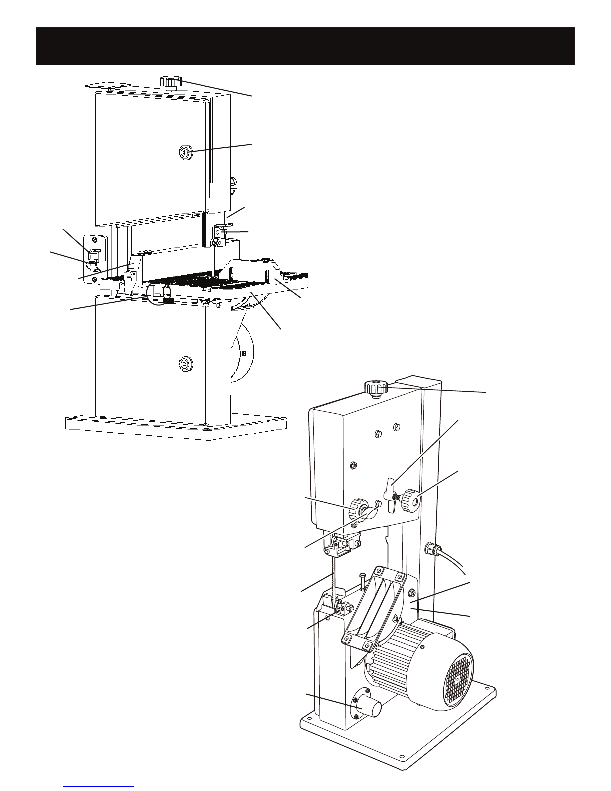
BLADE GUARD
Protects the operator from coming in contact
with the blade.
BLADE GUIDE ADJUSTMENT KNOB
Moves the blade guide assembly up and down,
and keeps the blade from twisting or breaking.
Always lock the blade guide assembly in place
before turning on the band saw.
BLADE GUIDES
Upper and lower blade guides helps keep the
blade from twisting during operation.
DUST EXHAUST PORT
A 1-1/2" dust exhaust port makes dustless
cutting possible. Attach a dust bag or a shop vac
to the dust exhaust port.
DOOR LATCH LOCK SCREW
Easy open latches allow front covers to be
opened for making adjustments.
MITER GAUGE
This gauge aligns the wood for a crosscut. The
easy-to-read indicator shows the exact angle for
a miter cut at 90° and 45°.
Page 5
BAND SAW FEATURES, CONTINUED
Switch
Switch
Key
Fence
Table
retainer
Blade tension
control knob
Door latch
lock screw
Blade guard
Upper blade guide
Miter gauge
Saw table
SAW BLADE
Saw includes a standard 1/4" blade.
SCALE
The scale and scale indicator show
the angle or degree the saw table is
tilted for bevel cutting.
SWITCH AND SWITCH KEY
Your band saw has an easy access
power switch. To lock in the OFF
position, remove the yellow switch
key. Place the key in a location
inaccessible to children and others
not qualied to use the tool.
TRACKING CONTROL KNOB
Adjusts tracking to keep blade
centered on the wheels.
ANGLE ADJUSTMENT KNOB
Loosening the table lock lever
allows the saw table to be tilted
at different angles. Tightening the
table lock lever locks the saw table
in place.
Blade guard
Blade guard
adjusting knob
adjustment knob
Blade guard
locking knob
Saw blade
Lower
blade guide
Dust
exhaust
port
Blade tension
Blade tensioner
control knob
Blade wheel lock knob
Tracking control knob
Angle adjustment
knob (on underside)
Scale
Page 6
SAW TABLE ASSEMBLY
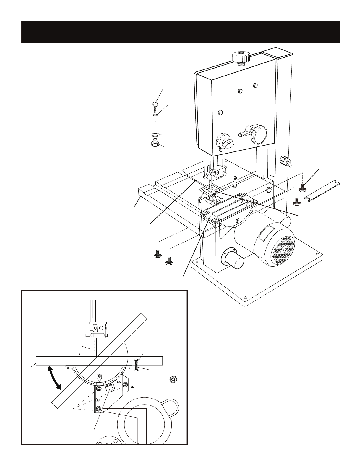
Using the four bolts provided,
attach the table to the
trunnion, tightening the bolts
after all four have been tted.
Once attached, position the
2-sided table insert into the
square recess. The side of
the insert with beveled edges
should face upward when
performing 45˚ angled cuts.
ASSEMBLY
Bolt
Small
Washer
Big
Washer
Lock nut
Saw table
Work table
locking
locking nut
screws
Table
set square
Saw table
Work table
Blade install Slot
Saw table supportSaw table support
level stop
screw
Lower nut
Angle scale
Lock knob
Wrench
Table insert
Table support
The level stop screw is adjustable. Using
a square, level the table to the blade as
shown. Once level is achieved, tilghten the
lower nut against the saw housing.
Table position
adjusting bolts
Angle adjustment knob
Page 7
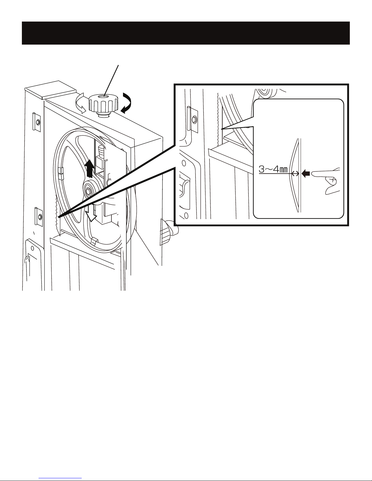
SAW SET-UP
Blade tension adjusting knob
Blade tension control knob
Loosen
Tighten
WITH THE MACHINE UNPLUGGED, adjust the blade tension with the blade tension control knob
on top of the upper housing. Turning the knob clockwise tightens the blade; turning the knob counter-
clockwise loosens the blade. Note: When increasing the tension on a loose blade, be sure to keep
the blade centered on the upper and lower wheels.
"Pluck" the back of the blade, as you would the string of a double bass, at the point shown in the
drawing. As blade tension increases, the pitch of the sound rises when the blade is plucked. Stop
increasing the tension as soon as the sound starts to become dull. Alternatively, raise the blade guard
to its highest position and adjust tension until the blade, at the midpoint between table and guard, can
be deected only 3 to 4 mm with nger pressure.
Once the blade is properly tensioned, set the travel of the blade on the upper wheel by using the
tracking control knob at the rear of the machine. Slowly rotate the upper wheel by its spokes while
watching the blade. If the blade does not stay centered and "walks" forward or backward, adjustment
is required. Turn the blade wheel lock knob counter-clockwise 2 rotations; this will allow the blade
to be adjusted with the tracking control knob. Turn the tracking control knob clockwise to move the
blade backward as you rotate the wheel by hand; turn the knob counter-clockwise to move the blade
forward. Adjust slowly until the blade runs centered, then tighten the blade wheel lock knob.
Page 8
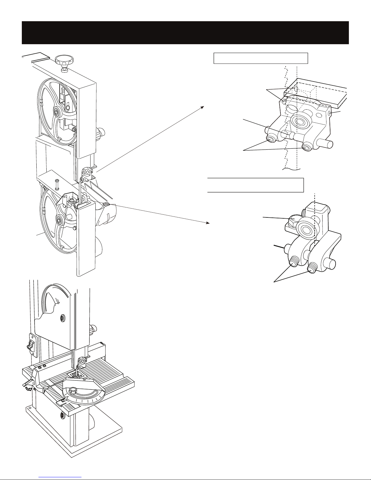
UPPER BLADE GUIDE
Front,back and angle
adjustment
Locking screw
Guide pin
SAW SET-UP, CONTINUED
Lower blade guide
Guide bearing
Guide pin
Locking screw
The upper and lower thrust bearings and guide pins should be
set-up next.
The thrust bearing should be about 0.5 mm behind the back of
the blade. Adjust it and lock it place.
Slacken the guide pin locking screws, then push the pins in
until they touch the blade. Rotate the top wheel by hand a few
turns and lock the pins in the position they have assumed. They
should be behind the teeth and against the spine of the blade.
The lower thrust bearing is adjusted similarly.
This band saw is equipped with a rip fence and a miter gauge
which can be tted as shown.
Your band saw is now ready for use, but it is recommended
that it be bolted to a bench and that a suitable dust extractor be
tted.
Page 9
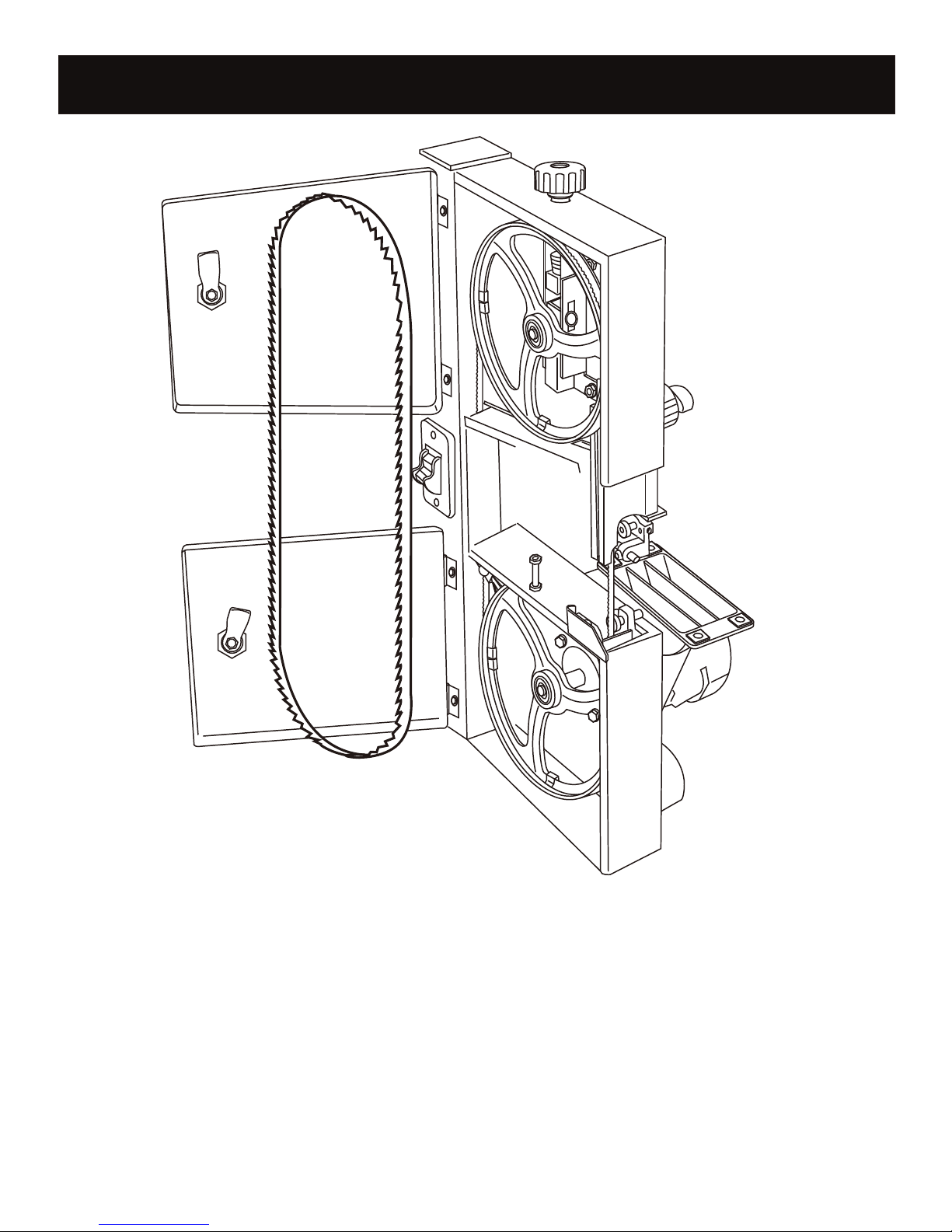
BLADE CHANGE
Table not shown in picture for
clearer view only; table does not
have to be removed for blade change
Band saw blades are sharp enough to cause injury even when too blunt to cut wood!
It is recommended that protective gloves be worn when handling blades.
Unplug the band saw from the power source, slacken off the blade tension and open the upper and
lower housing doors with the aid of hex key provided.
Remove the blade retainer from the table.
Slide the blade off the upper and lower wheels, bringing it out of the machine via the slots in the rear
frame and the blade guard. Reverse these steps to t the new blade. Ensure that the teeth are at the
front and pointing down.
Position the blade between the guide pins. Tension and adjust the tracking as done during the initial
set-up. Check and adjust, if necessary, the position of the two thrust bearings and the guide pins.
Page 10
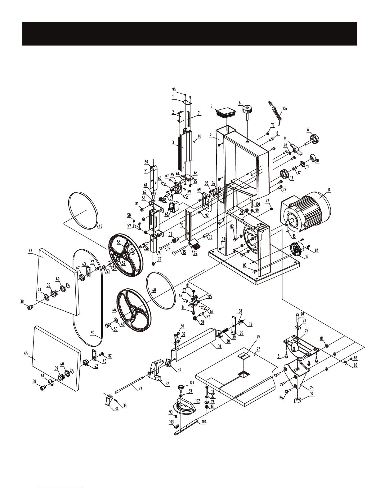
PARTS DIAGRAM
Page 11
socket head screw+wave washer
PARTS LIST
NO. Description Qty NO. Description Qty
1 upper guide bar plate 1 54 ball bearing 2
2 sliding plate 1 55 upper wheel 1
3 upper guide bar 1 56 upper wheel shaft 1
4 frame assy. 1 57 connecting shaft 1
5 Frame seal cap 1 58 split washer 2
6 tension lever 2 59 guide support assy. 1
7 Rack 1 60 U type support 1
8 hex flange bolt 9 61 butterfly spring shaft 1
9 wing type nut 1 62 butterfly spring 11
10 lock knob 2 63 upper guide base 1
11 spring pressure palte 1 64 guide base connecting shaft 1
12 lock spring 1 65 upper guide 1
13 guide adjustable knob 1 66
14 motor assy. 1 67 inner hex lock screw 8
15 flat key 1 68 switch 1
16 dust port 1 69 switch plate 1
17 hex bolt 1 70 guide block 1
18 worktable lock knob 1 71 adjustable gear 1
19 big flat washer 1 72 carriage bolt 1
20 carriage bolt 1 73 brush sleeve 1
21 sliding block 1 74 brush 1
22 worktable asupport 1 75 carriage bolt 1
23 worktable angle support 1 76 flat washer 1
24 carriage bolt(zincing) 3 77 strain relief 2
25 worktable cap plate 1 78 hex flange bolt 2
26 worktable 1 79 hex nut 1
27 lock screw 1 80 hex lock nut 1
28 rip fence lock plate 1 81 hex flange nut 9
29 rip fence lock spring 1 82 hex screw+spring screw+flat screw 6
30 rip fence washer 2 83 worktable pointer 1
31 rip fence plate 1 84 philips screw 3
32 rip fence bracket 1 85 flange nut 3
33 locknut 1 86 philips screw 9
34 rip fence lock knob 1 87 adjustable shaft2 2
35 flexible round pin 1 88 ball bearing 2
36 hex bolt 2 89 adjustable shaft3 1
37 flat washer 5 90 blade 1
38 lock cylinder 2 91 philips screw 4
39 lock sleeve 2 92 philips screw 2
40 lock washer 2 93 philips screw+spring washer+flat 3
41 w
42 hex thin nut 2 95 philips self-tapping screw 4
43 tongue plate 2 96 flexible round pin 1
44 upper door assy. 1 97 upper wheel shaft base 1
45 lower door assy. 1 98 Pain washer 1
46 lower wheel 1 99 hex screw 1
47 snap ring 1 100 hex head bolt 1
48 rubber washer 2 101 miter gauge lock knob 1
49 big flat washer 1 102 miter gauge 1
50
51 spring nut 1 104 bevel connecting bar 1
52 wave washer 1 105 lower guide 1
53 snap ring 1 106 Plug 1
ave washer 2 94 outer toothed lock washer (zincing 2
1 103 miter gauge pointer 1
adjustable shaft 1 3
 Loading...