

Page 1

Microlink 770
Man ual
Biodata Limited
Page 2

Man ual Code: 770PDF-1.1
Is sue Date: November 2015
Information in this document is subject to change without notice.
Updates are listed on our web site at
http://www.microlink.co.uk/techsupp.html
Biodata Limited 2011http://www.windmill.co.uk/help/http://www.windmill.co.uk/help/http://www.windmill.co.uk/help/
10 Stocks Street
Manchester M8 8QG
UK
Telephone: +44 (0)161 834 6688
Facsimile: +44 (0)161 833 2190
E-mail: [email protected]
http://www.microlink.co.uk/
Page 3

Table of Contents
1 Introduction 1.1
2 Installing the Microlink 770 USB Unit 2.1
2.1 Plugging the Microlink 770 into the Computer 2.1
2.2 The Microlink’s Lights 2.1
2.3 Analogue Input Connection Notes 2.2
2.4 Clock and Trigger Connection Notes 2.7
2.5 Specifications 2.9
2.6 The 59x Screw Terminal Units 2.10
3 Installing Windmill Software 3.1
3.1 Introduction 3.1
3.2 Installing Windmill Software 3.2
3.3 Configuring Your System 3.3
4 Using Windmill with Microlink 770 Hardware 4.1
4.1 Introduction 4.1
4.2 Using SetupIML 4.1
4.3 The Rest of the Windmill Software Suite 4.8
I
Table of Contents
Page 4

II
Microlink 770 Man ual
Page 5

Introduction
Thank you for pur chas ing the Microlink 770 High Speed Cap ture
Pack age. This Man ual tells you:
• About the Microlink 770 unit and how to con nect your
signals (Chap ter 2)
• How to in stall the Wind mill soft ware (Chap ter 3)
• How to use Windmill with the 770 unit
(Chap ter 4)
To use the 770 sys tem you need a PC with a USB port. It should be
run ning Win dows 98SE, Win dows 2000 or later.
The Microlink 770 unit plugs into the USB (uni ver sal se rial bus)
socket of your com puter. It pro vides the PC with 16 an a logue volt age
in puts, which you can sam ple up to 100 000 times a sec ond. When
Microlink 59x sig nal con di tion ing units are added, you can also use the
770 to mon i tor thermocouples, cur rent, strain gauge bridges and bal anced bridges such as pres sure transducers. The 59x units also allow
you to make your con nec tions to screw ter mi nals, rather than to the
37-way D con nec tor.
Here is a brief list of the fea tures of a Microlink 770 sys tem.
• In de pend ent in put ranges let you mix dif fer ent types of
mea sure ments—thermocouples and 4-20 mA pro cess
signals for ex am ple–with out los ing res o lu tion (set with the
SetupIML soft ware mod ule).
• Use the 770 to switch on other equip ment si mul ta neously
with the start of data cap ture (Sec tion 2.4.4).
• Save data both be fore and af ter an event oc curs (pre- and
post-trig ger data). Use ful for see ing, for ex am ple, what
hap pened im me di ately be fore a fault. (Set with the
Streamer soft ware mod ule.)
1.1
Introduction
Page 6

• A dig i tal in put into the 770 lets other equip ment trigger
data cap ture (Sec tion 2.4.2).
• Al ter na tively wait un til 1 or 2 read ings cross a thresh old
be fore au to mat i cally start ing to col lect data. For ex am ple,
when the tem per a ture goes above or be low your set
points (set with Streamer).
• Ex clude chan nels from a scan. This lets you use the 770
with dif fer ent set-ups with out hav ing to re wire, and maxi mises the speed of data cap ture. (Set with SetupIML.)
• Set both the in ter val be tween read ing each chan nel (ther -
mo cou ple, strain gauge, etc), and how of ten all chan nels
are read. For ex am ple, you may choose to wait a mil li sec ond be tween read ing each chan nel, but af ter the last
chan nel has been read pause for 10 sec onds be fore start ing again. (Avail able from both SetupIML and Streamer.)
• For more ac cu rate tim ing than your com puter clock al lows,
you can con nect an ex ter nal crys tal-con trolled clock
( Section 2.4.3).
• All re sults pre sented in en gi neer ing units:
o
C, oF, etc (set
with SetupIML).
1.2Introduction
Microlink 770 Man ual
Page 7

Installing the
Microlink 770 USB Unit
This chap ter tells you how to con nect your sig nals to the Microlink
770, and about the 59x screw ter mi nal units. After mak ing your con nec tions see Chap ter 3 for de tails of in stall ing the Wind mill soft ware.
2.1 Plugging the Microlink 770 into the
Computer
Plugging the Microlink into your PC could not be eas ier: just use the
USB cable pro vided. You don’t have to switch off your com puter
first—or even restart Win dows.
The Microlink 770 is pow ered from the USB port. Un less you are
using strain gauges, you don’t need an extra power sup ply unit.
2.2 The Microlink’s Lights
The Microlink 770 has a green light la belled ENUM and a red light
la belled BUSY. Neither of these will come on until you have in stalled
the Wind mill soft ware.
ENUM ENUM stands for Enumerated. This is lit when the
Microlink has been powered on by the USB plug and
play controller. It is a good indication that the Windmill
USB driver software has been correctly loaded.
BUSY This is lit for the duration of each USB communication. It
is not active until the Microlink has been enumerated.
2.1
Installing the Microlink 770 USB Unit
Page 8

2.3 Analogue Input Connection Notes
The Microlink 770 pro vides 16 dif fer en tial an a logue input chan nels
which you can use to mea sure volt ages. With the ad di tion of 59x units
you can also mon i tor thermocouples, cur rent, strain gauge bridges and
balanced bridges like pres sure trans duc ers.
2.3.1 Differential Inputs
All the in puts are dif fer en tial: for each input sig nal there are two sig nal wires. The mea sure ment is the dif fer ence in volt age be tween the
two wires. The two sig nals go into sep a rate high-im ped ance am pli fi ers
which mon i tor the volt age be tween the input and ground. The out puts
of the two am pli fi ers are then sub tracted to give the dif fer ence be tween
the + and – in puts. For small sig nals dif fer en tial in puts are much better
than sin gle-ended in puts. This is be cause the sub trac tion of the volt ages on each of the input wires means that any volt age com mon to
both wires is re moved, thus re duc ing noise.
It is im por tant to re mem ber that the volt ages at both in puts must be
within the am pli fier op er at ing range. A clas sic error is to con nect a bat tery be tween pos i tive and neg a tive in puts with no other con nec tion.
Al though the dif fer ence be tween the in puts is well de fined, the ac tual
volt age at each input could be any thing. Con necting one end of the bat tery to the 0 V input, ei ther di rect or via a re sis tor, would solve the
prob lem.
The 0 V of the Microlink 770 is con nected to com puter earth, which
is usu ally con nected to the mains earth. When mak ing your con nec tions you should fol low this pol icy.
a. If your signal source is “floating”, i.e. has no reference to mains
earth, then you must provide a reference by connecting one end of
it to the 0 V input, either direct or via a resistor. The resistor could
have any value up to several MΩ. However large values could
cause 50 Hz problems if your signal source has much leakage to
earth.
2.2Installing the Microlink 770 USB Unit
Microlink 770 Man ualAnalogue Input Connection Notes
Page 9
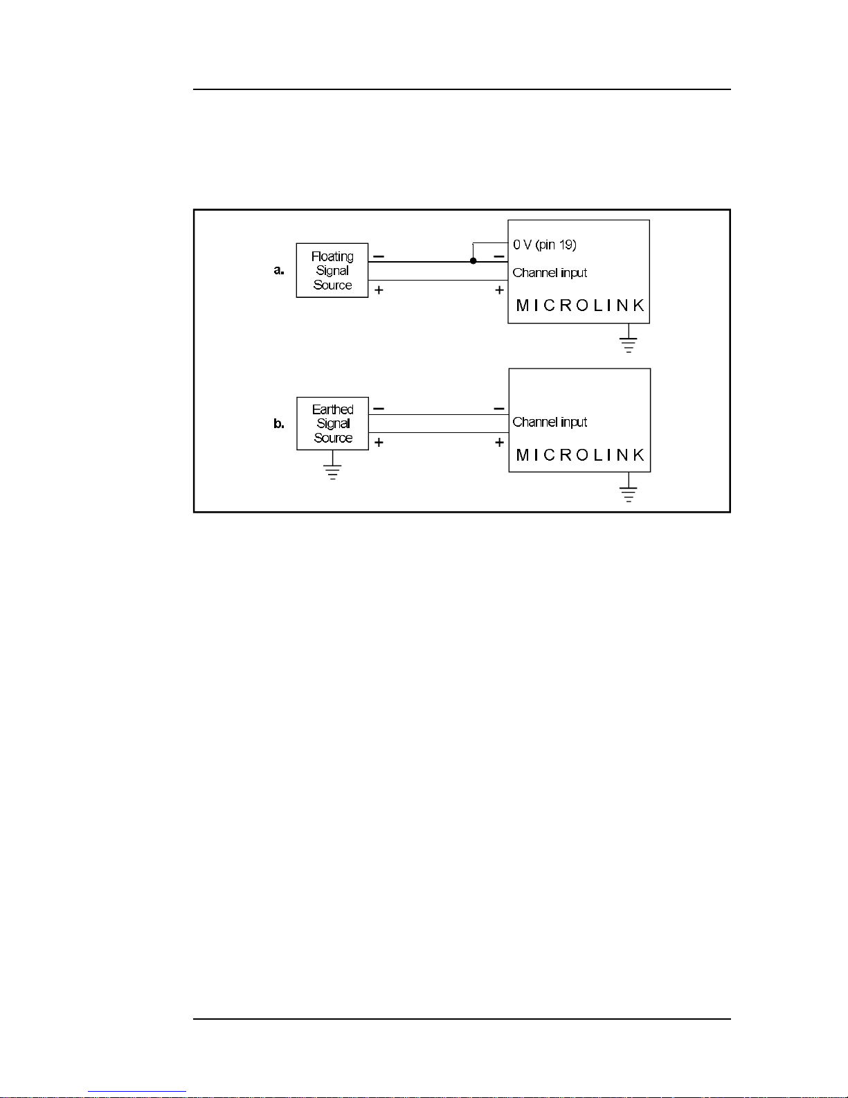
b. If your signal source is itself earthed then you should connect only
positive and negative inputs. You should make no connection to
Microlink 770 earth.
2.3.2 Input Voltage Range
The Microlink 770 op er ates cor rectly with input volt ages in the
range ±11 V. The in puts will re ject volt ages which are com mon to both
pos i tive and neg a tive in puts. These com mon mode volt ages could be
as big as 10 V.
2.3.3 Maximum Input Voltage
The input multiplexers are pro tected to 20 volts be yond the power
sup ply. This means ±35 V if the Microlink is switched on, ±20 V if it is
switched off. When a volt age above the power sup ply is ap plied to the
unit, its pro tec tion mech a nism comes into ac tion and this draws some
cur rent from the sig nal source. This ef fect can be a prob lem when the
com puter is switched off as it now draws cur rent from any sig nal. Extra
se ries re sis tors can be added to re duce this fault cur rent. Such re sis tors will also pro tect the unit from much higher volt ages. How ever, they
Analogue Input Connection Notes2.3
Installing the Microlink 770 USB Unit
Figure 2.1 For floating signals you need to connect one end
of the signal to the 0 V input on pin 19
Page 10

will re sult in higher noise and slower sam pling rates. The extra re sis tors
can be con ve niently housed on a 590 screw ter mi nal unit.
2.3.4 Unconnected Inputs
You can leave un used in puts un con nected, but if you at tempt to
read from these un con nected in puts do not ex pect to get 0 V. They
could be any value. If an other con nected chan nel has re cently been
read, the un con nected input will re turn a sim i lar value. This is not
crosstalk. It oc curs be cause the input ca pac i tance of the am pli fier is
charged to the volt age of the pre vi ous chan nel and has lit tle in cen tive
to change when con nected to an open cir cuit.
2.3.5 High Impedance Signals
A sim i lar ef fect to that de scribed above can occur with high im ped ance sig nal sources. When the source is se lected it must sup ply
cur rent to charge the am pli fier input ca pac i tance. A high im ped ance
sig nal source may take some time to do this so slow ing the max i mum
sam pling rate.
2.3.6 Auxiliary Input
This input has all the fa cil i ties of the other six teen. In Wind mill soft ware it is re served for mea sur ing cold junc tion tem per a tures with
thermocouples or ex ci ta tion volt age in bridge cir cuits. When you use a
593 ther mo cou ple input unit or a 594 bridge input unit, the aux il iary
input is au to mat i cally con nected as re quired by the soft ware.
2.3.7 Use with Microlink 593 Thermocouple Input Unit
When used with this unit the aux il iary input is au to mat i cally con nected to the cold junc tion sen sor. This is an RTD (re sis tance
tem per a ture de vice) with 0.8 mil li am pere flow ing through it. If in puts
are un con nected the ther mo cou ple break de tec tion cir cuitry will cause
them to read pos i tive full scale.
Pins 18 and 37 (–15 V and +15 V) pro vide a power sup ply for the
593—don’t con nect any other sig nals to these pins.
2.4Installing the Microlink 770 USB Unit
Microlink 770 Man ualAnalogue Input Connection Notes
Page 11

2.3.8 Use with Microlink 594 Bridge Input Unit
When used with this unit the aux il iary input au to mat i cally measures
the ex ci ta tion volt age con nected to the 594.
2.3.9 Analogue Input Pin Numbers
Make your con nec tions to the an a logue 37-way D con nec tor as
detailed in the table.
Analogue Input Connection Notes2.5
Installing the Microlink 770 USB Unit
Page 12

2.6Installing the Microlink 770 USB Unit
Microlink 770 Man ualAnalogue Input Connection Notes
19 0 V
+15 V 37
18 –15 V
+ Auxiliary 36
17 – Auxiliary
+ Input 15 35
16 – Input 15
+ Input 14 34
15 – Input 14
+ Input 13 33
14 – Input 13
+ Input 12 30
13 – Input 12
+ Input 11 31
12 – Input 11
+ Input 10 30
11 – Input 10
+ Input 9 29
10 – Input 9
+ Input 8 28
9 – Input 8
+ Input 7 27
8 – Input 7
+ Input 6 26
7 – Input 6
+ Input 5 25
6 – Input 5
+ Input 4 24
5 – Input 4
+ Input 3 23
4 – Input 3
+ Input 2 22
3 – Input 2
+ Input 1 21
2 – Input 1
+ Input 0 20
1 – Input 0
Please read the Connection Notes on the previous pages before
making your connections.
Microlink 770 - 16 An a logue In puts
Pin Con nec tions for 37-Way D Plug (Wiring View)
Page 13

2.4 Clock and Trigger Connection Notes
If you are using an ex ter nal clock or trig ger, make your con nec tions
to the 15-way dig i tal con nec tor. (If you are using Streamer soft ware for
trig ger ing and tim ing you can ig nore this sec tion.)
2.4.1 Inputs
The + in puts are tied to 0 V, and the – in puts to 5 V, by 10K re sis tors.
This means that you may safely leave the in puts un con nected. Volt ages ap plied should be re stricted to the range 0–5 V.
2.4.2 External Trigger Inputs
There are 2 trig ger in puts to ac com mo date pos i tive and neg a tive
edge trig ger ing. For a ris ing edge to ini ti ate sam pling, con nect your sig nal to Trig ger +. For a fall ing edge to ini ti ate sam pling, con nect your
sig nal to Trig ger –. In both cases leave the un used input un con nected.
Your trig ger pulse should be at least 1 µsec wide.
2.4.3 External Clock Inputs
There are 2 ex ter nal clock in puts to ac com mo date pos i tive and neg a tive edge tim ing. To ini ti ate a scan on a fall ing edge, con nect your
sig nal to Ex ter nal Clock –. For a ris ing edge to start a scan, con nect
your sig nal to Ex ter nal Clock +. Your clock pulse should be at least 1
µsec wide.
The ac tive edge of the clock pulse causes each an a logue chan nel
to be sam pled in turn from the first to the last. Er rors will re sult if an other
clock pulse oc curs be fore the pre vi ous scan is fin ished.
Use the Wind mill SetupIML soft ware to con trol the num ber of
channels in cluded in the scan, and Wind mill Streamer to set the in ter val be tween sam pling each chan nel.
Clock and Trigger Connection Notes2.7
Installing the Microlink 770 USB Unit
Page 14

2.4.4 Trigger Output
This out put goes to 5 V when the unit starts to sam ple. You can use
it as a trig ger to syn chro nise ex ter nal equip ment with the Microlink 770.
The out put stays at 5 V until sam pling stops.
2.4.5 Digital Pin Numbers
Make your con nec tions to the dig i tal 15-way D con nec tor as
detailed below.
1 RUN Out put Sig nal
5 V when the 770 is sam pling
Use to trig ger ex ter nal events
2 Ex ter nal Trig ger In put –
A fall ing edge on this in put trig gers the Microlink 770
3 Ex ter nal Trig ger In put +
A ris ing edge on this in put trig gers the Microlink 770
4 Ex ter nal Clock –
A fall ing edge on this in put causes one full scan to be taken
5 Ex ter nal Clock +
A ris ing edge on this in put causes one full scan to be take
8 0 V
All sig nals are 5 V logic lev els. The + in puts are tied to 0 V by 10K
resistors. The – in puts are tied to 5 V by 10K re sis tors.
2.8Installing the Microlink 770 USB Unit
Microlink 770 Man ualClock and Trigger Connection Notes
Page 15

2.5 Specifications
2.5.1 Microlink 770 Unit
Di men sions (mm) 180 x 120 x 40
Max i mum length of ca ble 5 m per ca ble
Max i mum dis tance from PC can be in creased by use of USB hubs
2.5.2 Analogue Inputs
Num ber of in puts 16
Max i mum safe in put volt age
Com puter on ±35 V
Com puter off ±20 V
Volt age Ranges ±10 V, ±1 V, ±0.1 V
Com mon mode range ±10 V
A-D Res o lu tion 16 bits
Through put 100 kHz
Max i mum lin ear ity er ror ±0.02%
In put im ped ance 100 MΩ
Crosstalk 75 dB
On re sis tance ~400 Ω
Switch off leak age <2 nA
In put bias cur rent ±30 nA
Set tling time to 0.01% 15 µsec
Ini tial ac cu racy of gain and off set ±1 LSB
In put noise volt age 2 µV rms
2.5.3 Trigger and Clock Inputs and Outputs
Sig nal com pat i bil ity 5 V logic level
Run out put (ex ter nal trig ger) 5 V when sam pling
Trig ger in put – Trig ger on fall ing edge
Trig ger in put + Trig ger on ris ing edge
Ex ter nal clock – Scan starts on fall ing edge
Ex ter nal clock + Scan starts on ris ing edge
+ In puts Tied to 0 V by 10K re sis tors
– In puts Tied to 5 V by 10 K re sis tors
Specifications2.9
Installing the Microlink 770 USB Unit
Page 16

2.6 The 59x Screw Terminal Units
The Microlink 59x range pro vides screw ter mi nals for the Microlink
770, al low ing you to per ma nently wire your sig nals . These 59x units sit
next to the Microlink 770. Some of the 59x range allow trans duc ers like
thermocouples and strain gauge bridges to be mon i tored by the 770.
Extra fa cil i ties are avail able when com po nents are fit ted, such as pro tec tion from high volt ages. There are 3 units you can use with the
Microlink 770.
Microlink 590 Screw Ter mi nals
Microlink 590-8a Screw Ter mi nals with Cur rent Mea sure ment
Microlink 593 Screw Ter mi nals with Tem per a ture Mea sure ment
Microlink 594 Screw Ter mi nals with Strain Mea sure ment
The 59x range is op tional, so you can ig nore the rest of this Man ual if
you have bought just the Microlink 770 and Wind mill pack age.
2.6.1 Microlink 590 Unit—Screw Terminals
The 590 is a boxed screw ter mi nal card. Extra fa cil i ties avail able
with this card in clude:
• noise fil ter ing,
• in put pro tec tion from high volt ages,
• higher volt age in puts than nor mal,
• con tact clo sure in puts,
• ac in puts,
• cur rent to volt age con ver sion,
• bi as ing to ground,
• ex ter nal cur rent source switch ing,
• pro gram ma ble re sis tance.
CONNECTION
The 590 unit has space for 3 rows of 18 screw ter mi nals. The row
near est the front panel is con nected to pin 19 of the an a logue D con nec tor on the front of the Microlink. This pin is con nected to 0 V. The
other 2 rows are con nected to pins 1–18 and 20–37 as in di cated by the
small fig ures by the ter mi nals.
2.10Installing the Microlink 770 USB Unit
Microlink 770 Man ualThe 59x Screw Terminal Units
Page 17

FITTING AP PLI CA TION COM PO NENTS
Se ries Com po nents
Com po nent posi tions S1 to S37 (0.4 inch pitch) are avail able to
mount com po nents in series with D-type pins 1 to 37. Only S1
and S37 are named on the PCB because of lack of space. How ever the num ber ing sequence is the same as that of the nearby
B1 to B37 com po nents. To fit a com po nent in series with, for
exam ple, pin 10
• Place the com po nent in the S10 po si tion (level with B10),
• Sol der it on the cop per side,
• Cut the track un der S10 at the point where it nar rows.
The main appli ca tion of series com po nents is series pro tec tion
resis tors. These could have any value from hun dreds of ohms to
meg ohms depend ing on require ments.
Par al lel Com po nents
Com po nent posi tions P0 to P17 (0.2, 0.3, 0.4 inch pitch) are pro vided to mount com po nents across ana logue inputs 0 to 15, 16
is the aux il iary input, 17 com pletes the pat tern. Com po nents can
be sim ply sol dered into these posi tions.
In put Fil ters
Low pass ana logue input fil ters can be pro duced by fit ting resis tors in the 2 series ele ments of an ana logue chan nel, and a
capac i tor in the par al lel ele ment. For instance a fil ter can be
imple mented on chan nel 1 by fit ting resis tors to S2 and S21 and
a capac i tor to P1. Typ i cal val ues would be 10 KΩ and 1 µF.
These would pro duce a cut off fre quency of about 8 Hz.
2.6.2 Microlink 590-8a Unit—Screw Terminals with
Current Measurement
The 590-8A is a boxed milliamp cur rent de tec tion card, ar ranged as
8 cur rent and 8 volt age in puts. The same extra fa cil i ties are avail able
with this card as with the 590.
The 59x Screw Terminal Units2.11
Installing the Microlink 770 USB Unit
Page 18

2.6.3 Microlink 593 Unit—Screw Terminals with
Temperature Measurement
The Microlink 593 is an iso ther mal box spe cial ised for mon i tor ing
thermocouples. It in cludes a cold junc tion sens ing RTD with an as so ci ated con stant cur rent source (0.8 milliamps). The RTD de ter mines the
tem per a ture at the ter mi na tion point. This ref er ence tem per a ture is
used with the an a logue input chan nel’s volt age read ing to cal cu late the
tem per a ture at the ther mo cou ple junc tion.
The Wind mill soft ware au to mat i cally con nects the cold junc tion to
the aux il iary chan nel and com pen sates for it. It reads the chan nel di rectly, show ing the cold junc tion tem per a ture in Cel sius.
Pro tec tion from high volt age in puts is pro vided when se ries re sis tors are added. Noise prob lems can be solved by fit ting an input fil ter
and bro ken ther mo cou ple leads can be de tected.
The cold junc tion sens ing cir cuitry is lo cated be tween the two
leftmost rows of screw ter mi nals. This cir cuitry is con nected by the PCB
to the aux il iary chan nel. Bias re sis tors are fit ted to pro duce a small cur rent through the thermocouples. This al lows ther mo cou ple break
de tec tion.
2.12Installing the Microlink 770 USB Unit
Microlink 770 Man ualThe 59x Screw Terminal Units
Page 19

2.6.4 Microlink 594 Unit—Screw Terminals with Strain
Measurement
The 594 is a boxed 16 bridge in puts card, which en ables the 770
unit to mon i tor strain gauge bridges and bal anced bridges such as
pres sure trans duc ers.
For strain gauges you need an ex ter nal ex ci ta tion volt age, which
can sup ply suf fi cient cur rent to keep all the bridge cir cuits energised.
Four sets of 16 screw ter mi nals give + and – ex ci ta tion and + and – sig nals for each of 16 bridges. Two 1 kΩ ter mi na tion re sis tors are mounted
in half bridge con fig u ra tion whilst high qual ity 350 and 120 Ω re sis tors
can be pro vided for the com ple tion of quar ter bridges. The aux il iary
chan nel of the 770 unit mon i tors the ex ci ta tion volt age.
When mon i tor ing a bridge input, the Wind mill soft ware au to mat i cally reads ex ci ta tion volt age and per forms the bridge cal cu la tion to
pro duce a read ing in microstrain. You can set a zero ref er ence level
and mon i tor changes rel a tive to that level.
With the 594 unit you can con fig ure each input chan nel for any of
the fol low ing in puts.
volt age in put
quar ter bridge sin gle strain gauge
half bridge ten sile + com pres sive strain gauge
half bridge nor mal + trans verse strain gauge
full bridge 2 ten sile + 2 com pres sive gauges
full bridge 2 nor mal + 2 trans verse gauges
full bridge ten sile nor mal + com pres sive nor mal +
ten sile trans verse + com pres sive trans verse
gauges
The fig ure on page 15 shows the gen eral ar range ment of the
Microlink 594. For each input chan nel (0–15) there are 5 screw ter mi nals. These are ar ranged in 5 rows la belled, 0V, +EX , —EX, +IN, –IN,
with the chan nel num ber printed by each ter mi nal. Com mon to all chan nels are the POWER INPUT ter mi nals and two pre ci sion re sis tors
con nected across the power sup ply to form a half bridge. The power
The 59x Screw Terminal Units2.13
Installing the Microlink 770 USB Unit
Page 20
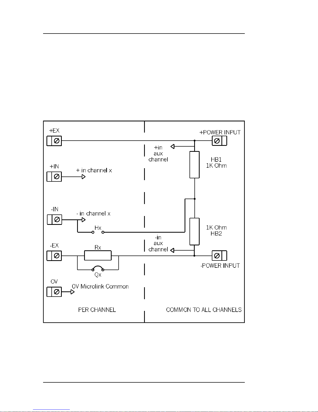
input ter mi nals are di rectly con nected to the aux il iary chan nel of the
770. Wind mill soft ware reads this chan nel to mea sure the ex ci ta tion
volt age for use in the bridge equa tions. Each chan nel has as so ci ated
with it 2 link mount ing po si tions and one re sis tor po si tion. These are:
Rx Po si tion for mount ing a quar ter bridge com ple tion re sis tor
Qx Link to short out the quar ter bridge com ple tion re sis tor
Hx Link to con nect the half bridge to the –IN of chan nel x
2.14Installing the Microlink 770 USB Unit
Microlink 770 Man ual
Gen eral Ar range ment of Microlink 594
Page 21
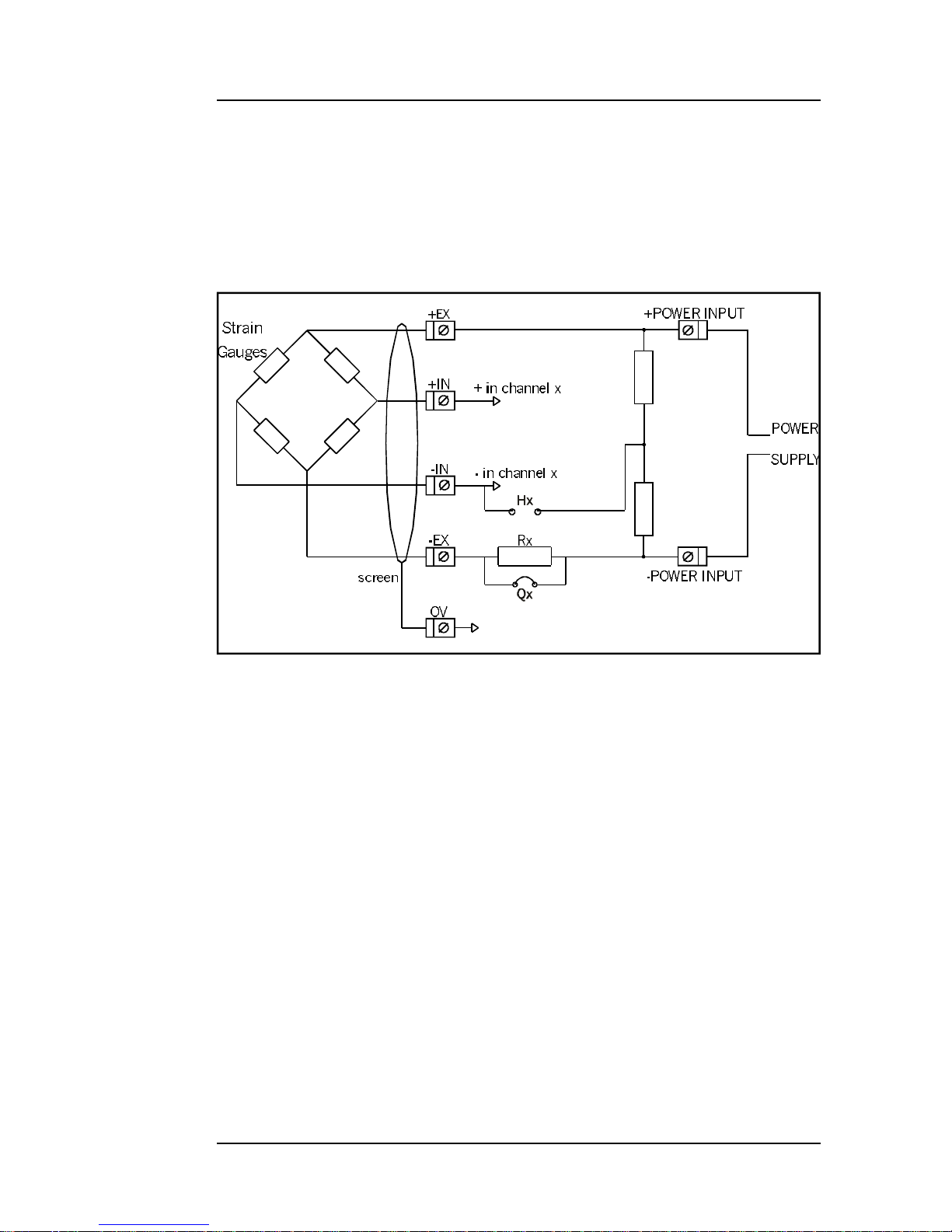
Full Bridge Con nec tion
The fig ure below shows a full bridge con nec tion. The Qx quar ter
bridge link must be fit ted to con nect the –POWER INPUT to the –EX.
Four wires are needed to con nect your bridge and the earth is avail able
for a cable screen.
The 59x Screw Terminal Units2.15
Installing the Microlink 770 USB Unit
Microlink 594 Full Bridge Con nec tion
Page 22
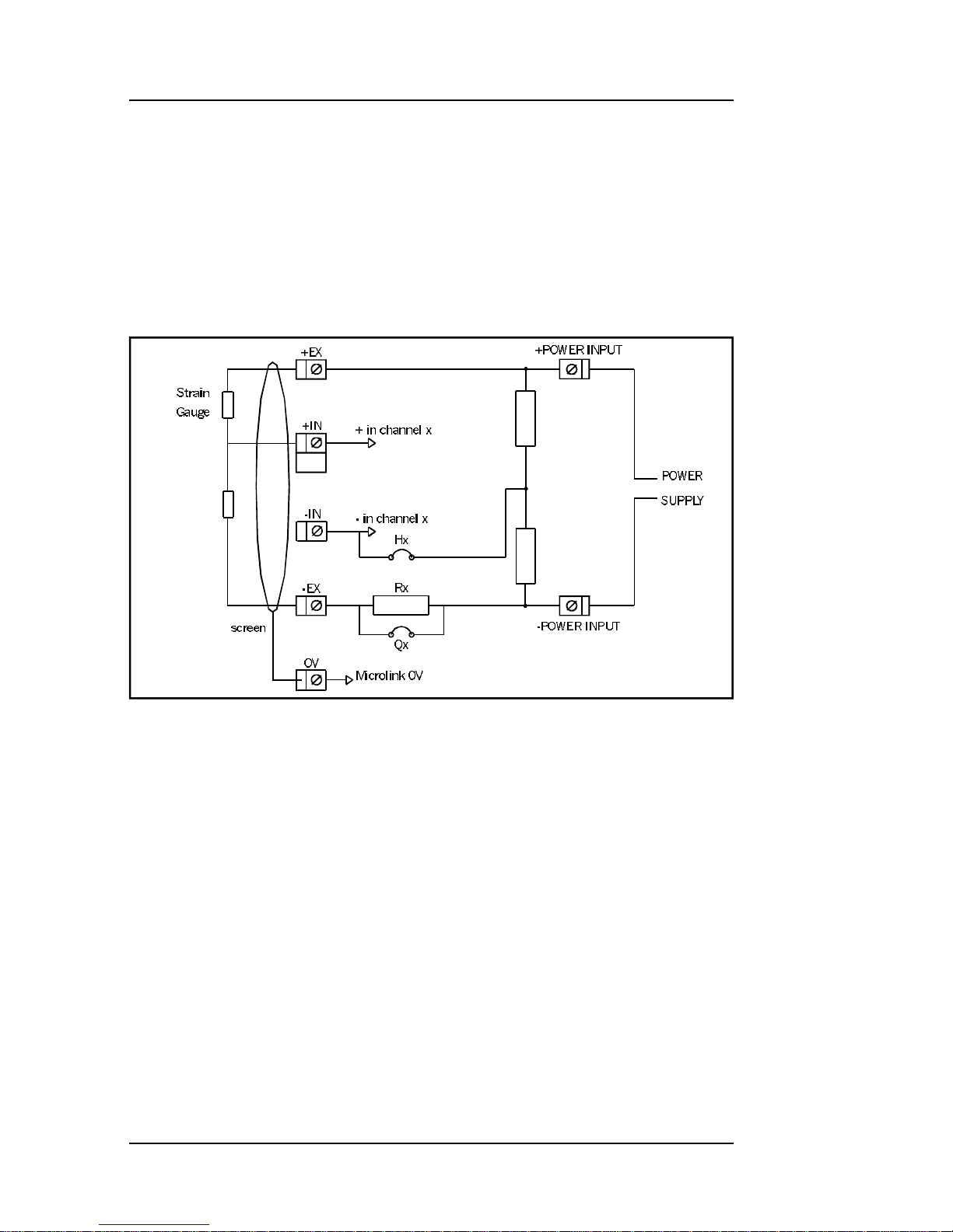
Half Bridge Con nec tion
This fig ure shows a half bridge con nec tion. The Hx and Qx links
must both be fit ted. The Hx link con nects the half bridge to the –IN of
the chan nel, whilst the Qx link con nects the –POWER INPUT to the
–EX. Three wires are needed to con nect your bridge and the earth is
avail able for a cable screen.
2.16Installing the Microlink 770 USB Unit
Microlink 770 Man ualThe 59x Screw Terminal Units
Microlink 594 Half Bridge Con nec tion
Page 23
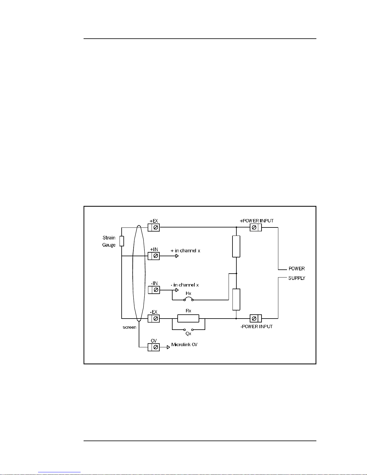
Quar ter Bridge Con nec tion
The fig ure below shows a quar ter bridge con nec tion. The Hx link
con nects the half bridge to the –IN. The Rx bridge com ple tion re sis tor
must be fit ted. This re sis tor should be a high pre ci sion, low tem per a ture
co ef fi cient de vice. Its value should be the same as the nom i nal re sis -
tance of your strain gauge, 120 and 350 Ω being the com mon est
val ues. In other ap pli ca tions it should be cho sen to bal ance the bridge
near the cen tre of your mea sure ment range. For in stance if you are
mak ing pre cise RTD mea sure ments around am bi ent tem per a ture then
100 Ω would be suit able. If how ever you were mon i tor ing higher tem per a tures a suit ably larger value would be cho sen.
It is nor mal prac tice when mak ing a quar ter bridge con nec tion to
take all 3 wires to the trans ducer. This bal ances out the ef fects of lead
re sis tance.
The 59x Screw Terminal Units2.17
Installing the Microlink 770 USB Unit
Microlink 594 Quar ter Bridge Con nec tion
Page 24

Power Sup ply
The bridges must be pow ered by an ex ter nal power sup ply. The
volt age used should be cho sen by the user to suit his ap pli ca tion. The
cur rent re quire ment can then be cal cu lated as fol lows:
Full Bridge cur rent = volt age / Rg
where Rg = gauge re sis tance
usu ally 120 or 350 Ω
Half or Quar ter Bridge cur rent = volt age / (2*Rg)
Typ i cal Ex am ples
16 * 120 Ω quar ter bridges with 10 V exci ta tion. These use
42 mA per bridge mak ing a total of 0.67 amps.
16 * 350 Ω full bridges with 10 V exci ta tion. These use 28 mA per
bridge mak ing a total of 0.45 A.
Con nec tion of Power Sup plies
Power sup plies are often float ing de vices, i.e. they are not ref er enced to mains earth. If this is the case a con nec tion must be made
from Microlink 770 0 V to the power sup ply neg a tive. This can eas ily be
done on the Microlink 594. If this is not done, the bridge out put volt ages
may be be yond the range of the 770 input am pli fi ers and false read ings
will re sult.
If sev eral 594 units are used on a com mon power sup ply, each
should be given its own con nec tion to the power sup ply. This mini mises the cur rent flow ing in any par tic u lar power sup ply wire, and so
re duces volt age drop in the wires.
2.18Installing the Microlink 770 USB Unit
Microlink 770 Man ual
Page 25

Installing Windmill Software
3.1 Introduction
Wind mill is a ready-to-run suite of ap pli ca tions for data ac qui si tion
and con trol. You can be up and run ning in very lit tle time as no
programming is re quired. The stan dard suite in cludes data log ging and
chart ing ap pli ca tions. You can also trans fer data directly into third-party
ap pli ca tions like Microsoft Excel. Other Windmill mod ules are
available—see the Wind mill Soft ware Internet cat a logue for de tails
http://www.windmillsoft.com/.
Full de tails of using the soft ware are given in the Wind mill
programs’ Help. Here we ex plain how to:
1. Install the Windmill measurement and control software on your
computer.
2. Configure the software by telling it what type of measurement
hardware you have connected to your computer.
3. Choose the settings to use with the Microlink 770.
Make sure you have con nected your Microlink 770 to the PC be fore
in stall ing Wind mill.
Introduction3.1
Installing Windmill Software
Page 26

3.2 Installing Windmill Software
For in stal la tion you will need a per sonal com puter run ning Microsoft
Win dows 98 or later, with at least 8 MB RAM.
1. Insert the CD-ROM into the CD drive. Windows should detect the
CD and automatically start the installation program. If it doesn’t,
then run the setup.exe program on the CD.
2. At the end of installation, the Configuration
program—ConfIML—starts. This asks you for details of your data
acquisition hardware and the default working directory. See
Section 3.3 for details.
3.2.1 Upgrading From Earlier Versions of Windmill
You can run Wind mill along side ear lier ver sions of the soft ware.
Once you are happy that you no lon ger need a pre vi ous copy of
Windmill sim ply run its “Uninstall” pro gram to de lete it.
3.2.2 Running Several Copies of Windmill
Un less you have bought a mul ti ple licence, you are only per mit ted
to run one copy of the soft ware at any one time. Please con tact your
supplier if you re quire a mul ti ple licence.
3.2Installing Windmill Software
Microlink 770 Man ualInstalling Windmill Software
Page 27

3.3 Configuring Your System
The Wind mill Con fig u ra tion pro gram, ConfIML, re cords the de tails
of your data ac qui si tion hard ware. It will run at the end of the in stal la tion
pro cess, and you should run it again from Win dows when ever your
acquisition hard ware changes—for ex am ple when you in stall ad di tional units. For sug ges tions on the set tings to choose in ConfIML
press the Help but ton.
The first thing you need to do is press the Add but ton to in clude your
Microlink 770 unit.
Configuring Your System3.3
Installing Windmill Software
The main ConfIML win dow be fore you have added the Microlink 770.
Page 28

3.3.1 Adding New Hardware
When you press the Add but ton in the main ConfIML win dow, the
Add IML Hard ware di a logue ap pears. This lists the ac qui si tion and
control devices for which you have in stalled driv ers.
Se lect a de vice and press Add. You will now see the Hard ware
Settings dialogue (Sec tion 3.3.2).
Re peat for any other de vices you plan to use.
3.3.2 Changing Hardware Settings
ConfIML needs to know some in for ma tion about your 770 unit.
Press the Help but ton or see below if in doubt about the an swers. The
Default but ton will reset all the answers to the Microlink’s default
set tings.
Which Type of Card do you have?
Choose the Microlink 770.
Which Type of Trans ducer Con nec tion Unit is At tached?
There are three options. Which you choose depends on the 59x
units you have con nected.
None/Gen eral Pur pose
Choose this if you:
• are not us ing a 59x unit,
• are us ing a 590 screw ter mi nal volt age unit, or
• are us ing a 590-8A screw ter mi nal cur rent unit.
3.4Installing Windmill Software
Microlink 770 Man ualConfiguring Your System
Adding New Hard ware De vices to the Wind mill Sys tem
Page 29

Ther mo cou ple
Choose this if you are us ing a 593 ther mo cou ple ter mi nal
unit.
This mon i tors the tem per a ture of con nec tions, which is
es sen tial when us ing thermocouples. You can use chan nels not re quired for thermocouples for gen eral volt age
mea sure ment.
Strain Bridges
Choose this if you are us ing a 594 strain gauge bridge
con nec tion unit.
This mon i tors an ex ter nal bridge ex ci ta tion sup ply so that
strain gauge out puts can be con verted into read ings in
microstrain. Again, you can use chan nels not re quired for
strain for gen eral volt age mea sure ment.
Press OK and the Microlink 770 should be listed as:
Microlink 770 USB An a logue In puts
Microlink 770 Unit - Clock
3.3.3 Setting the Working Directory
When you use Wind mill you will cre ate two types of files, those
which hold data and those which hold the Wind mill pro grams’ set tings.
You can spec ify a de fault folder in which to store these files— known as
the Working Di rec tory. Ini tially the work ing di rec tory is set to wher ever
you in stalled Wind mill. To change this, press the Di rec tory but ton.
Choose a new di rec tory (folder) and press Save. Wind mill will cre ate two sub-di rec to ries under this choice, called setup and data. By
default, all the Wind mill set tings will be stored in “setup” and all the data
you col lect stored in “data”.
3.3.4 The ConfIML Main Window
The main ConfIML Win dow shows the hard ware de vice driv ers you
have added.
You can now:
Configuring Your System3.5
Installing Windmill Software
Page 30

• press Save to re cord the cur rent con fig u ra tion and close
ConfIML;
• press Add to in stall ad di tional hard ware;
• se lect an in stalled de vice and press Set tings to ad just the
set tings you spec i fied for that de vice (if any);
• Se lect an in stalled de vice and press Comms to ad just the
com mu ni ca tions pro to col for that de vice (if any);
• se lect an in stalled de vice and press Re move to de lete that
de vice from the list;
• press Soft ware to author ise your soft ware;
• press Di rec tory to change your work ing di rec tory;
• press Can cel to close ConfIML with out sav ing the
changes.
You must save a con fig u ra tion which lists at least one de vice driver
be fore you can use any other Wind mill pro grams.
After clos ing ConfIML start the SetupIML pro gram and choose how
you wish to use the hard ware. SetupIML will use the first de vice in the
ConfIML Hard ware De vice list as De vice 0—the de fault de vice. For
more on using SetupIML ei ther see its Help or refer to Chap ter 3.
Re mem ber that if you make any changes to your data ac qui si tion
hard ware you must re-run ConfIML and up date the configuration.
3.3.5 The Software Signal Generator
In ad di tion to data ac qui si tion and con trol hard ware, ConfIML lists
the soft ware sig nal gen er a tor. This is a spe cial driver which sim u lates a
de vice with seven chan nels, each chan nel pro duc ing a dif fer ent sig nal.
No spe cial hard ware is re quired—the data val ues are pro duced by
calculation.
The soft ware sig nal gen er a tor lets you ex per i ment and prac tise with
Wind mill. Note though that you can not use it with the Wind mill
Streamer pro gram.
3.6Installing Windmill Software
Microlink 770 Man ual
Page 31

3.3.6 The IML Device Icon
When ever you run a Wind mill pro gram one or more IML De vice
icons will ap pear. Dif fer ent icons iden tify dif fer ent hard ware driv ers.
The Wind mill ap pli ca tions can’t run with out these, so don’t close them
whilst using Wind mill.
3.7
Installing Windmill Software
Page 32

Page 33

Using Windmill with
Microlink 770 Hardware
4.1 Introduction
This chap ter de scribes how to use the SetupIML pro gram to spec ify
how you want to use in di vid ual chan nels. It also gives brief notes on the
other Wind mill pro grams.
You should have al ready:
• con nected the Microlink 770 to your com puter’s USB port,
• plugged any 59x unit into the Microlink 770 and
• wired your sig nals
as de scribed in Chap ter 2.
4.2 Using SetupIML
Use SetupIML to spec ify how you want to use in di vid ual hard ware
chan nels. You save these spec i fi ca tions in a file which is later re called
by the Wind mill log ging and dis play pro grams. You can save a li brary of
these setup files for dif fer ent projects or ex per i ments.
SetupIML lets you
• View the mod ules and chan nels in the hard ware,
• Choose which chan nels are in volved in the cur rent setup,
• Give names to the chan nels,
• Se lect the mode, range and data for mat for chan nels
where ap pro pri ate,
• Set up en gi neer ing unit con ver sion where ap pro pri ate,
• Set tim ing and clock de tails.
4.1
Using Windmill with Microlink 770 Hardware
Page 34

When SetupIML starts it in ter ro gates the hard ware and builds a
default setup file. You can then edit this file, tai lor ing the sys tem to your
needs.
While SetupIML is run ning it con stantly checks each op er a tion with
the hard ware to spot any er rors. Make sure, there fore, that your
Microlink is connected and switched on be fore start ing SetupIML.
For full de tails of using SetupIML se lect its Help menu. Here we de scribe those set tings most per ti nent to the Microlink 770, high light ing
the im por tant set tings when using the 770 with the Wind mill Streamer
high speed data cap ture soft ware.
4.2.1 Starting SetupIML
The first time you start SetupIML you need to “cre ate a new setup”.
Once you have named the setup file and pressed OK, SetupIML in ter ro gates the hard ware and builds a de fault setup ready for ed it ing. The
main win dow then ap pears. You can use most of the set tings as they
are—but if you plan to use Streamer to col lect data at high speed you
must turn off auto-rang ing (Sec tion 3.4.24.2.3). SetupIML de faults to
auto-rang ing be cause with slower soft ware than Streamer this is the
“best guess”. Auto-rang ing, how ever, is too slow for Streamer. When
you’ve turned off auto-rang ing, and the other set tings are to your lik ing,
close the file. You are now ready to use Streamer.
4.2.2 Selecting The Microlink 770
The Microlink 770 should be shown in SetupIML as two mod ules:
770Anin and 770Clck. Anin stands for an a logue in puts and lists the 16
mea sure ment chan nels. Clck stands for Clock and al lows you to set the
tim ing and trig ger ing op tions for the mea sure ment chan nels.
If the 770 is not shown, se lect it from the De vice menu.
4.2Using Windmill with Microlink 770 Hardware
Microlink 770 Man ual
Page 35

4.2.3 Configuring an Analogue Measurement Channel
You can customise each chan nel, chang ing such things as their
names, range and en gi neer ing units.
Se lect a chan nel to con fig ure ei ther by dou ble-click ing the mouse
over the chan nel, or by using the arrow keys on the key board and
press ing the Re turn but ton.
The con fig u ra tion di a logue box for the se lected chan nel ap pears.
If the di a logue box does n’t ap pear, you may be in Se lect Chan nels
mode and should swap to Con fig ure Chan nels mode. If chan nels are
greyed out then re-in clude them en ter ing Se lect Chan nels mode and
dou ble-click ing the clock chan nel.
Dis abling Chan nels
When con fig ur ing an an a logue chan nel, the Usage area lets you set
the di rec tion of the chan nel: input, out put, input and out put or nei ther.
4.3
Using Windmill with Microlink 770 Hardware
Page 36

For Streamer you should set those chan nels you want to in clude in
the scan to input, and those you don’t want read ings from to nei ther
input nor out put—thus dis abling the chan nels.
Set ting the Range
The range of the mea sure ment chan nel you have se lected is
shown in the Input Range / Mode box. Se lect the small est range that
en com passes your sig nals. (Small ranges are gen er ally more ac cu rate
than large ones.) When using Streamer don’t se lect auto-rang ing as
this is too slow.
The Set tling Time
When using Streamer soft ware, the set tling time for the an a logue
chan nel is re placed by chan nel in ter val set tings in the clock op tions
(Sec tion 4.2.4).
The Alarms But ton
Streamer is op ti mised for high speeds and so does n’t sup port
alarms.
Maxi mising Streaming Speed
1. Disable unused channels (Section 4.2.3).
2. Turn off auto-ranging (Section 3.4.24.2.3).
4.4Using Windmill with Microlink 770 Hardware
Microlink 770 Man ual
Page 37

4.2.4 Setting the Clock and Trigger Options
Streamer scans all en abled an a logue input chan nels at high speed,
tak ing a read ing from each chan nel in turn from the first to the last. The
time be tween scans is the Scan In ter val. The time between each
channel read ing is the Chan nel In ter val.
To maxi mise scan speed and re duce the vol ume of data col lected
you should dis able all chan nels that are not needed (clear the Usage
check boxes on the an a logue chan nel di a logue box, Sec tion 4.2.3).
To set the high speed op tions dou ble-click the 770 clock chan nel.
This di a logue ap pears.
Some set tings are dis abled as the 770 does n’t use these fa cil i ties.
Note: the high speed op tions are only sup ported by the Streamer
pro gram, and not by the other Wind mill pro grams such as Log ger or
DDE Panel.
4.5
Using Windmill with Microlink 770 Hardware
Page 38

Set ting the Clock Source
Scans are taken reg u larly ac cord ing to a clock. This clock may be
an in ter nal clock, in which case you use SetupIML to set a Scan Interval
or Fre quency (Sec tion 4.2.4). Al ter na tively you can con nect an ex ter nal
clock to the Microlink hard ware. Now Streamer will take ini ti ate a scan
at each ac tive edge oc cur ring at the clock input of the Microlink. See
the Microlink 770 Hard ware User Man ual for de tails of con nect ing an
external clock.
Un like many other of your choices in SetupIML, you can not change
the clock source from within Streamer.
Set ting the Scan In ter val or Scan Fre quency
The scan in ter val is the time be tween the start of one scan and the
start of the next. The scan fre quency is the num ber of scans taken each
sec ond. Changing ei ther set ting will cause the other to be re cal cu lated.
You can also change the scan in ter val and fre quency in the Streamer
pro gram.
Set ting the Chan nel In ter val
The chan nel in ter val is the time be tween sam pling one chan nel and
the next dur ing the scan. To change the chan nel in ter val erase the cur rent value and type in a new one (in mil li sec onds). The chan nel in ter val
must be small enough to allow all en abled an a logue chan nels to be
read within the time al lowed for each scan.
In creasing the chan nel in ter val may pro duce a more ac cu rate read ing, es pe cially for sig nals with dif fer ent ranges, but the max i mum scan
rate is re duced.
You can also change the chan nel in ter val in Streamer.
Set ting the Trig ger Source
Data ac qui si tion starts when the Microlink re ceives a trig ger. The
trig ger may be a Soft ware trig ger. In this case sam pling be gins ei ther
when you se lect Start from Streamer, or when a spec i fied input crosses
a cho sen thresh old (set in Streamer). Al ter na tively you can se lect an
4.6Using Windmill with Microlink 770 Hardware
Microlink 770 Man ual
Page 39

Ex ter nal trig ger. Sam pling then starts from a logic pulse de rived from
some ex ter nal event. See Chapter 2 for wir ing de tails.
Set ting the Num ber Of Scans
One way of stop ping sam pling is to spec ify the num ber of scans re quired, after which data col lec tion will stop. This method can be used
re gard less of whether sam pling has been started by an ex ter nal or a
soft ware trig ger. To change the num ber of scans erase the cur rent
value and type in a new one.
You can also stop sam pling by press ing a Stop but ton in the
Streamer soft ware.
4.7
Using Windmill with Microlink 770 Hardware
Page 40

4.3 The Rest of the Windmill Software Suite
The Wind mill suite of soft ware that comes with the 770 comprises:
ConfIML, SetupIML, AnalogOut, DigitalOut , DDE Panel, Log ger, Chart
and Streamer.
For high speed ap pli ca tions, or to take ad van tage of the 770’s
tirggering op tions, use the Streamer soft ware. Streamer can stream
data from an a logue in puts di rectly to the com puter’s hard disk. Al ter na tively, for tran sient cap ture, Streamer saves data in mem ory and
cop ies it to disk when col lec tion has fin ished.
Dur ing col lec tion Streamer can dis play charts and ta bles of data. If
you need more so phis ti cated anal y sis or pre sen ta tion, you can share
data with other Win dows ap pli ca tions using dy namic data ex change
(DDE).
For full de tails of using Streamer see its Help. (Up dates to the Help
are avail able from http://www.wind mill.co.uk/help.html)
To be in formed when new Wind mill prod ucts are launched, sub scribe to the free Monitor news let ter (ISSN 1472-0221) at
http://www.wind mill.co.uk/news let ter.html. This also gives hints, tips
and ar ti cles on all as pects of data ac qui si tion and con trol.
4.8Using Windmill with Microlink 770 Hardware
Microlink 770 Man ual
Page 41

Index
590 screw ter mi nal unit 2.10
590-8A cur rent unit 2.11
593 ther mo cou ple unit 2.4, 2.12
594 bridge unit 2.5, 2.13
ac in put 2.10
an a logue in put 2.2-6
aux il iary in put 2.4-5, 2.12
bi as ing to ground 2.10
bridge in put 2.5, 2.13
chang ing hard ware set tings 3.4
chan nel in ter val 4.6
clock 2.7-8, 4.5
clock source 4.6
cold junc tion 2.4, 2.12
Con fig ure Chan nels mode 4.3
ConfIML 3.3-5
con tact clo sure 2.10
cur rent in put 2.11
dif fer en tial in puts 2.2-3
di rec tion 4.3
di rec tory 3.5
dis abling chan nels 4.3
earth 2.2-3
en abling chan nels 4.3
ex ter nal clock 2.7-8
ex ter nal trig ger 2.7-8, 4.7
fil ter 2.11-12
ground 2.2-3
high im ped ance 2.4
high volt age 2.10
in put fil ter 2.12
in put pro tec tion 2.10-12
in stall ing
Microlink 752 unit 2.1-18
Windmill software 3.1-7
iso ther mal box 2.12
Key board 4.3
low pass fil ter 2.11
maxi mis ing stream ing speed 4.4
Mode
Configure Channels 4.3
multiplexing 4.5
new hard ware 3.4
noise 2.10, 2.12
num ber of scans 4.7
plug 2.1
power 2.1
pres sure trans ducer 2.13
pri mary chan nel 4.5-6
pro gram ma ble re sis tance 2.10
range 2.3-4
re sis tance 2.10
scan in ter val/fre quency 4.6
screw ter mi nals 2.10-13, 2.15-17
SetupIML 3.6, 4.1-2
sig nal gen er a tor 3.6
soft ware 2.12-14
see Windmill software
soft ware sig nal gen er a tor 3.6
soft ware trig ger 4.6
spec i fi ca tions 2.9
stop ping sam pling 4.7
strain gauge bridge 2.5, 2.13
Streamer 2.12-14
tem per a ture mea sure ment 2.4, 2.12
i
Index
Page 42

ther mo cou ple 2.4, 2.12
trig ger 2.7-8
trig ger source 4.6
us age 4.3
Wind mill soft ware 2.1, 3.1-7, 4.1-8
ConfIML 3.3-5
earlier versions 3.2
installing 3.1-7
other modules 4.8
SetupIML 3.6, 4.1-7
several copies 3.2
work ing di rec tory 3.5
ii
Microlink 770 Man ual
 Loading...