

Page 1
UM5-CAM
User’s Guide
USB MICROSCOPE
Version 1.4A
Page 2

Page 3
Contents
Object
Quantity
Object
Quantity
USB Digital
Microscope
1
User’s Guide
1
Installation CD
1
Supporter
1
Calibrator
1
1. Product Introduction .......................................... 1
1.1 Packing Content ......................................... 1
1.2 USB Microscope Functions Introduction: .. 1
1.3 USB Microscope Operation: ...................... 2
1.4 USB Cable .................................................. 3
2. Installation ......................................................... 3
2.1 Insert Installation CD (Step 1) .................... 4
2.2 Install Application Program (Step 2) .......... 4
2.3 Exit Installation Program (Step 3) .............. 4
3. Application Program ............................................. 4
3.1 Video Preview Window .............................. 4
3.2 Image Preview Window ............................. 4
3.3 Main Menu ................................................. 5
3.4 Main Button ................................................ 5
3.5 Files List ..................................................... 6
3.6 Special Functional Modules ....................... 6
1. Product Introduction
1.1 Packing Content
1.2 USB Microscope Functions Introduction:
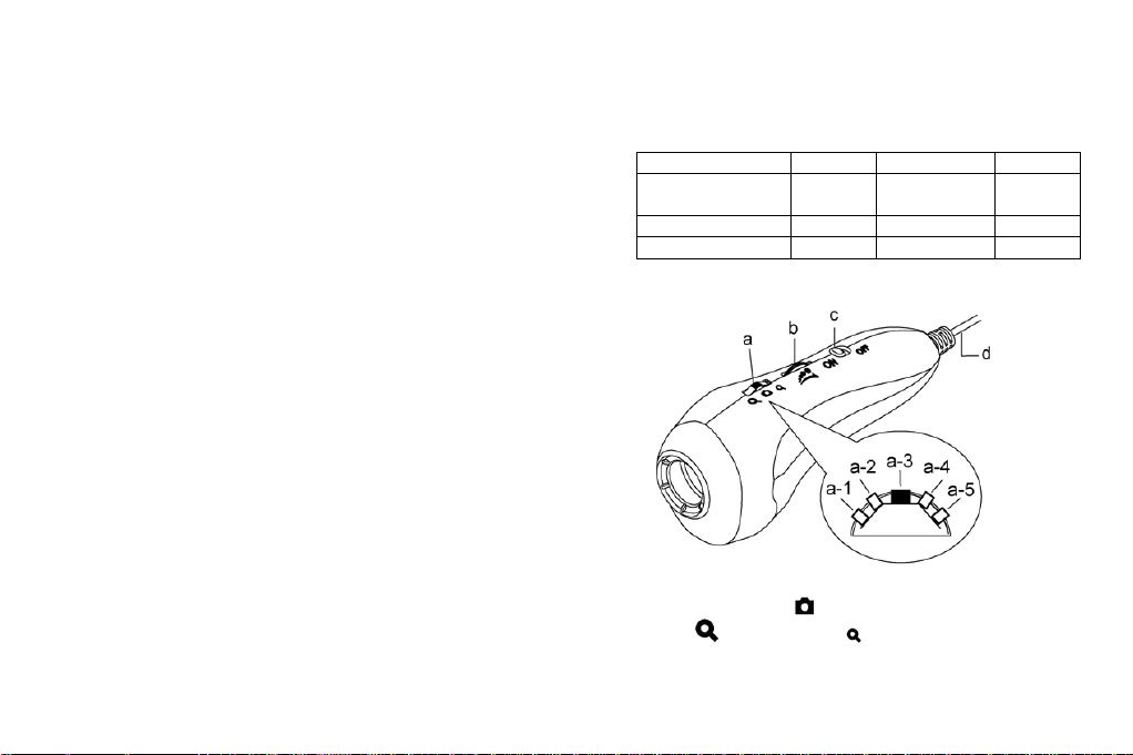
a. Five-Section Switch (hereafter ‘5-Switch’: Press down the
switch to take picture and turn forward/backward for
zooming in and zooming out .
1
Page 4
(a-1) Turn the switch forward to a-1 position is for quick
(High Mag.) Zoom in direction
(Low Mag.) Zoom out direction
Five-Section Switch
focusing (zooming in).
(a-2) Slightly tuning the switch forward to a-2 position for slow
focusing.
(a-3) Press down the switch for photography.
(a-4) Slightly tuning backward the switch to a-4 position for
slowly zooming out the image.
(a-5) Turn backward the switch to the end (a-5 position) is for
quickly zooming out.
b. Light Control Wheel: :Adjust LED brightness. Turn
forward to decrease brightness; on the contrary, turn backward
to increase brightness.
c. Auto-Focus (hereafter ‘AF’) button: Slide to position
means to switch on Auto-Focus function. Slide to
position means to switch off Auto-Focus function.
d. USB Port: It is USB2.0 port. Please connect it with PC USB
Port.
1.3 USB Microscope Operation:
a. Focus
There are different focus points. When turn forward the
5-Swtich can get higher magnification on the tiny object, and turn
backward can get lower magnification on the tiny object. For
long-shot, it is same webcam function; thus, it doesn’t have
magnifier function.
(1) Autofocus: The focus functions are Single AF and Continuous
AF . Single AF means to the device only focus one time by
itself. If the object moves, the image will become blurry.
On the contrary, Continuous AF means the device will re-focus
if the object moves again. Please refer to below instruction
for operating the Five-Section-Switch when AF is ON:
(a-1) Turn the 5-Switch forward to the end (a-1 position), it
will do Single AF for higher magnification.
(a-2) Slightly turn the 5-Swtich forward to a-2 position; it will
do Single AF for low magnification.
(a-3) Press down the dial to photography.
(a-4) Slightly turn the 5-Swtich backward to a-4 position, it is
to Switch the current focusing way
(a-5) Turn the 5-Switch backward to the end (a-5 position), it
will do Single AF of long-shot.
2
Page 5

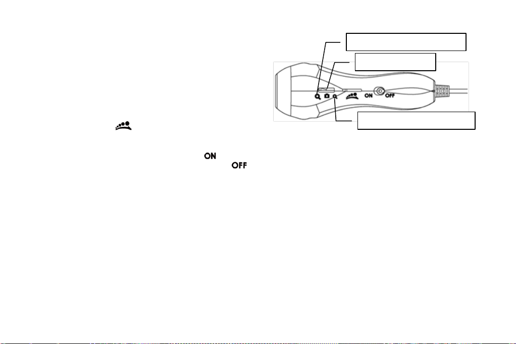
(2) Manual Focus: Push AF button to “OFF” position. Then
PC Connection
Object
Long-Shot
Object
Contacted
observation
Five-Section
Switch
Focus can down manually. Slightly turn forward for higher
magnification; slightly turn backward for lower magnification.
Please refer to [Section 1.2 item(1)].
b. Photography for contacted-observation: Horizontally put the
lens onto the observed object. There are 2 focus points under
contact observation, one is at lower magnification (hereafter (L
mag.)); the other is higher magnification (hereafter (H mag.))
1.4 USB Cable
The USB cable is already connected with the device; thus,
please do not try to remove the USB cable from the device.
The other USB joint is to connect with PC. Note: Please do
not use any USB extension cable.
c. Long Shot: For long shot and preview of Non-contact
observation. To turn the 5-Switch backward to L. mag
direction , till find clear image as long-shot focusing is done.
The magnification will vary per the distance between the object
and device. It can also apply as a webcam
2. Installation
For detailed program installation, please refer to the
Installation Manual set in the Installation CD (User's Manual \
English \ Microscope installation manual.pdf) Programs shall be
installed according to the following 3 steps:
Note: This device does not need to install the driver.
3
Page 6

2.1 Insert Installation CD
2.2
2.3
Insert Installation CD provided together with the product into
the CD-ROM. The CD will be run by computer automatically, and
the installation window will pop out as below:
If the computer does not pop out installation window, please
open the Installation CD folder and select “Autorun.exe”. See
Autorun image:
If the Installation CD provided together with the product is
missing or unknown damaged, please visit http://www.vitiny.com
to download installation files.
2.2 Install Application Program
Please click “Install Application Program”button.
2.3 Exit Installation Program
After installing Application Program, please click “Exit”
button to quit program installation.
3. Application Program
Operation Instruction of Application Program is divided into 6
parts which primary about AP operation. For detailed instructions,
please refer to the Operation manual set in the Installation CD
(User’s Manual \ English \Microscope Application Program
Operates Manual.pdf).
3.1 Video Preview Window
After connecting to microscope camera, the window will show
preview images. As well as video plays, image reviews, and
special function modules will shown in this same window.
3.2 Image Preview Window
4
Page 7

The window is applied to display shot images, edit and process
3.4
3.5
3.2 I
3.1
3.3
images.
3.3 Main Menu
The Main Menu of the Application Program contains the
following selections:
(1) File: open, save and print files.
(2) Setting:includes input device, image quality, video information
formats, sources and compression, as well as automatic storage,
etc.
(3) Window:you can adjust sizes of video information windows
and switch to the single window model.
(4) Tool:open saved file location, default file path, time lapse,
convert video to image, convert image to video..etc
functions….
(5) Language:five languages including Chinese in complex and
simple forms, English, Japanese and Germany are available for
selection.
(6) About: to show the version, copyright and other relevant
information about the Application Program.
3.4 Main Button
Main Button contains more general functions as follows:
(1) Connect / Disconnect : button of connecting and
disconnecting to microscope camera. Video image will be
displayed in Video Preview Window after connection.
(2) Snapshot :press the button to capture image from Video
Preview Window. The captured image will be displayed in
Images Preview Window.
(3) Save Image :store images in Images Preview Window
(4) Editor Image / Exit Editor :to enter or quit Image
Edition function. After entering, tools of image edition are
listed below Images Preview Window as follows:
5
Page 8

(5) Delete Image :Pressing delete Icon will delete image.
(6) Video Record / Stop Record :to record or stop
recording video. Recorded video will be displayed in Video
Preview Window. You can set compressed coding way by
clicking and selecting “Setting->Video Compression” in the
Main Menu. The user is suggested install DivX encoder to
achieve better compression results and quality.
(7) Play Video / Stop Play :to play or stop playing
video. Video of played files will be displayed in Video Preview
Window. Playing tools are listed below the preview window as
follows:
(8) Image Process / Exit Image Process : image
processing include reversed video, grey scale, black and white,
edge detection and other basic functions. After entering Image
Processing model, tools will be displayed below Images
Preview Window as follows:
(9) Print Image :print images displayed in Images Preview
Window.
(10) Exit :close the Application Program.
3.5 Files List
Files List is primarily applied to list all current files contained
in folders. Select BMP, JPG or AVI to view saved images/videos.
3.6 Special Functional Modules
Start and connect Application Program, the toolbars of Special
Function Modules will show below the Video Preview Window;
which includes: comparison, aming mode, image control,
measurement and far distance control mode. See below:
(1) Comparison mode :observe similarity of compared images
through overlapping and half-half comparison. Before using the
model, please load the image for application of other functions.
For tools of comparison model, please refer to the following
image:
(2) Aiming mode :This mode provides 4 different aiming aids,
which are cross, scope, rectangle and circular to aim at shot
objects as an auxiliary function. Please refer to the following
image for tools of the mode.
(3) Video control mode :you can take the device by your left or
right hand, adjust image direction of yourself or object, as well
as adjusting contrast, brightness and exposure rate of the image.
Please refer to the following image for tools of Image Control
Model.
(4) Measurment mode :the mode can be used as rulers and
compasses. Further, the model can measure in the dynamic
6
Page 9

(real-time image) or static (loaded images or frozen image)
images, as well as providing various measuring tools. Please
refer to the following image for tools of Measurement Model.
(5) Device control mode :This mode is to control the device
from AP directly without operate function button on the device.
From the AP control, users allow to photography, zoom in/out
image, and brightness control…etc.
7
Page 10

Page 11

© MicroLinks Technology Corp. All rights reserved.
HTTP://WWW.VITINY.COM
 Loading...