

Page 1
MADE IN ITALY
Page 2
TECHNICAL SPECIFICATIONS
Installation on the wall Coverage 15 mt, angle 90°
Frequency microwave 10.525 GHz
Alarm technology DSP(Digital Signal Processing)
Detecting distance From 3 to 15 mt
Detection areas 8 aeras for each sensor
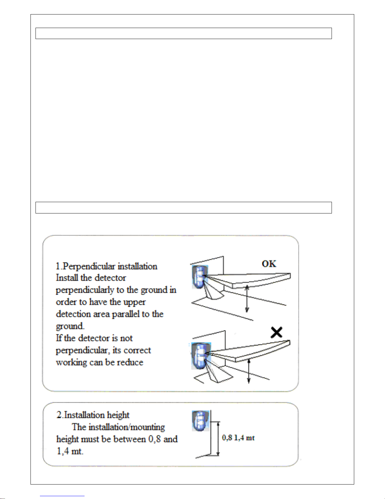
Installation height 0,8-1,4 m (reccomended 1mt)
Detecting mode Selectable: AND-OR
Power supply From 10,5 to 14 VDC
Power consumption Standby < di 1.5 mA
Max power consumption 12 mA X 4 SEC
Relay contact
NC 100mA
MW range adjustment By trimmer
Alarm time 1,2 sec
Light indicators LEFT RED : IR UPPER
RIGHT RED : IR LOWER
YELLOW : MICROWAVE
Detecting speed from 0.2 to 3.5 m/s
RFI/EMI immunity 3 V/m between 0.1MHz-500MHz
Light immunity >10000 Lux
Programming by dip Switch
Operating temperature From -10°C to +55° C
Protection rating IP54
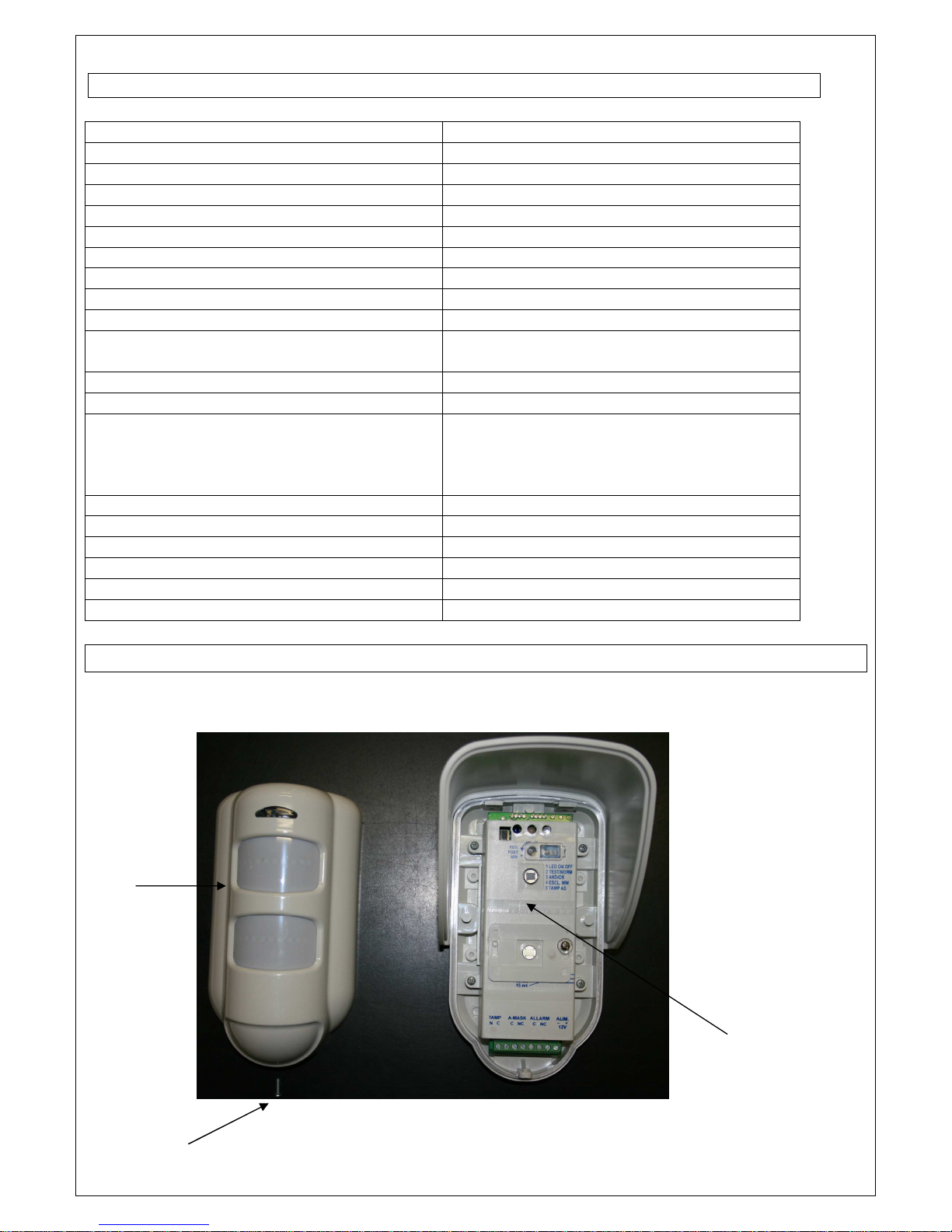
DESCRIPTION
Cover
Closing
screw
Electronic
part
Page 3
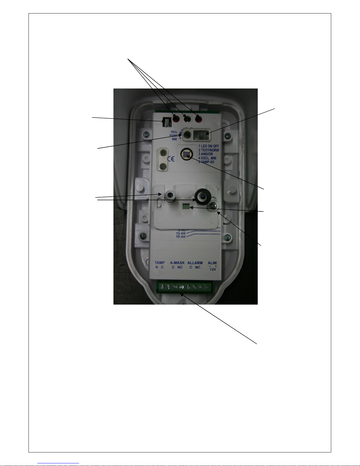
Led Indicator
Tamper
Microwave
Adjustement
Dip switch
PIR 1
PIR 2
PIR 2 Adjustement
screw
Terminal
Block
Antimasking Led
Page 4
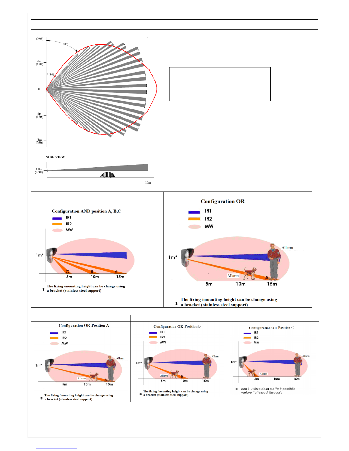
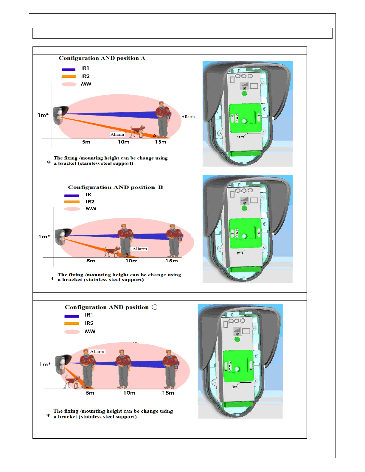
COVERAGE DIAGRAM
Configuration
AND position
A,B,C
Configuration
OR1
Configuration
OR 2
position A Configuration
OR 2
position
B
Configuration
OR 2
position
C
Detection plan view.
The microwave detection
covering area is in red.
Page 5
DETECTION
Configuration AND position A
Configuration AND position B
Configuration AND position C
Page 6
INSTALLATION METHOD
For a correct working of the Triple Technology Detector you have to
know that:
• The microwave is sensitive to any movement, do not point the
sensor towards hedges or tree branches. Adjust the range rightly.
• Metal surfaces reflect the microwave modifying the range
• The two passive infrared sensors are sensitive to rapid temperature
changes. Avoid to direct the sensor towards the sun (point the
sensor directly to the sun). In presence of animals adjust the
detection angle rightly.
• The detector has a regulation time of around 1 minute at the first
functioning.
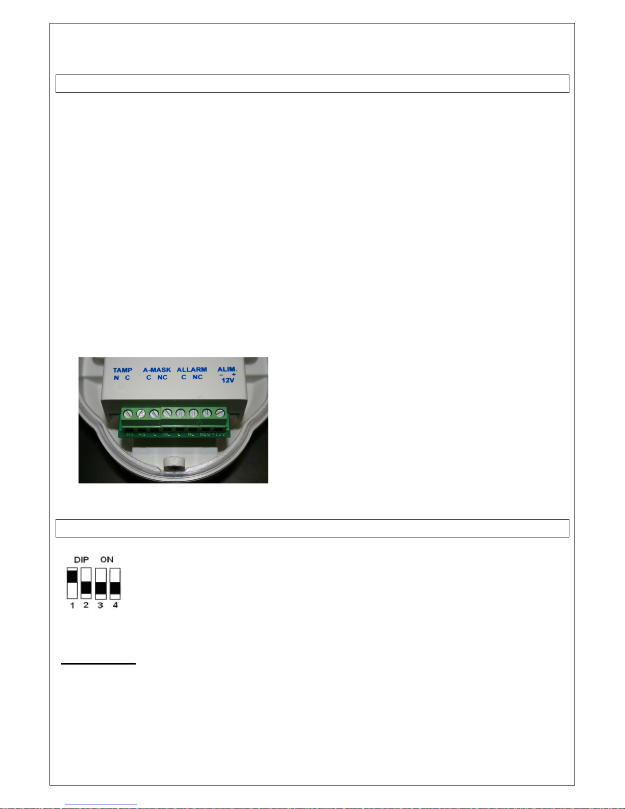
Terminal block
.
DETECTING OPTIONS
From the factory the
programming DIP are set like in
the figure.
DIP1: LED
With this DIP are activates or de-activates the LED indicators
with DIP1=ON light indicator enabled,
with DIP1=OFF light indicator disabled.
Page 7

DIP 2: ANTI MASK
Setting the DIP 2 in OFF anti-masking disabled.
Setting the DIP 2 in ON frontal anti-masking enabled by active infrared.
NOTE:
Open the detector, connect the power supply cables, close the detector
and power it.
Wait for 5 minutes for the stabilization of the system
If obscure the field detection of the detector and the dip 2 is ON, in a
maximum time of 10 seconds generates a tamper alarm (the output-mask
open) and remains in alarm as long as it remains the cause .
DIP3: “AND” FUNCTION
This function is activated setting DIP 3 in OFF position. In this
configuration, when the two infrared sensors and the microwave sensor
detect a movement, the detector, will trigger an alarm. This mode is
recommended in external environments with unstable elements may
cause a false alarm.
DIP 3: “OR” FUNCTION
This mode is activated setting DIP 3 in ON position. In this configuration,
when one of the two infrared sensors and the microwave sensor detect a
movement, the detector will produce an alarm. It is recommended in
completely external environments and in presence of small animals.
With this mode every small movement is detected.
DIP 4: MICROWAVE DE-ACTIVATION
DIP 4 in OFF. Microwave enabled.
DIP 4 in ON . Microwave disabled.
This mode refers to the microwave alarm detection.
In particularly narrow environments ( such as garage passages, gardens
pedestrian areas) it is reccommended setting DIP 4 in On position in
order to have the infrared sensors detection only. If you use this mode,
you will always set DIP 3 in Off position (AND mode).
Page 8
Setting Dip 1 in ON position
Check and adjust the covering area (see the previuos diagramm)
Move into the protecting area and check the specific indicators (LED)
switching on.
Considering that the two infrared sensors are sensitive to the across and not to
the approach.
If the detection do not meet the own needs you will adjust the microwave
range by the trimmer ( to put up turning in an anticlockwise direction and to put
down turning in an clockwise direction) or you will adjust the sensor inclination
angle. N.B. When the microwave detect a movement too, the detector will
produce an alarm, the microwave is always turn off, it is activated with AND
mode if both the two infrared sensors detect an alarm. With OR mode if one of
the two infrared sensors detects an alarm.
INSTALLATION TIPS
WORKING/OPERATING TEST
Page 9
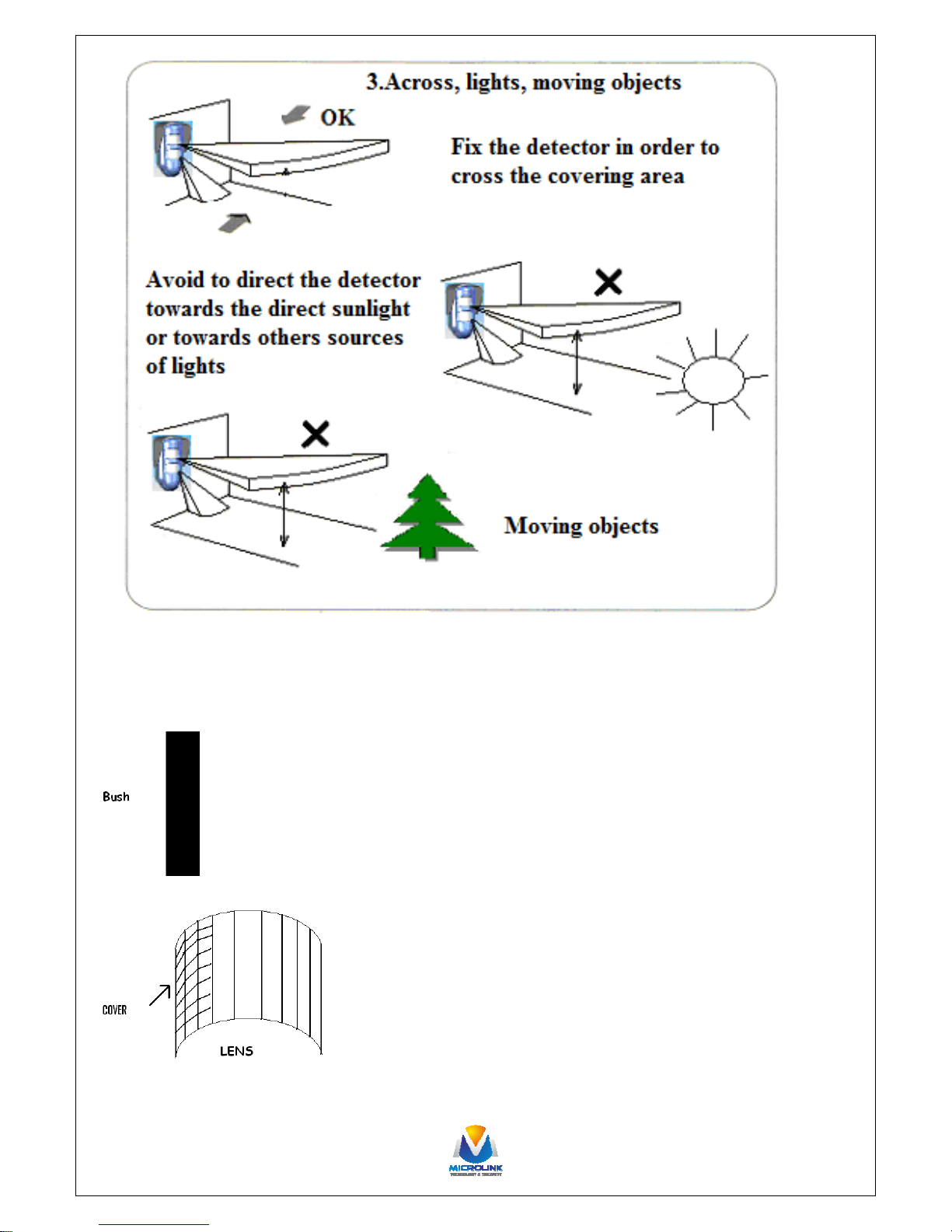
Caution /Take note
In presence of hedges or bushes, cover the beams infrared lens
corresponding to the plants like in the figure.
 Loading...