

Micro Linear Corporation ML6415CS Datasheet
ML6415 S-Video Filter with Summed Composite
Output, Sound Trap, and Group Delay Compensation
GENERAL DESCRIPTION FEATURES
The ML6415 is a dual Y/C 4th-order Butterworth lowpass
video fi lter optimized for minimum overshoot and fl at
group delay. The device also contains a summing circuit
to generate fi ltered composite video, an audio trap and
group delay compensation circuit to notch-out audio, providing an area for the addition of the FM audio carrier(s)
and mimic the group delay distortion introduced at the
transmitter. The group delay predistortion compensates
for the nominal TV receiver IF fi lter distortion.
In a typical application, the Y and C input signals from
DACs are AC coupled into the fi lter. Both channels have
DC restore circuitry to clamp the DC input levels during
video sync. The Y and C channels use a separate feedback
clamp. The clamp pulse is derived from the Y channel.
The outputs are AC coupled. The Y, C, CV, and modulator
outputs can drive 2Vp-p into a 150Ω load (1Vp-p 75Ω
coax load). The Y, C, CV, and notch channels have a gain
of approximately 2 (6dB) with 1Vp-p input levels.
n 7.1MHz Y and C fi lters, with CV out
n 14dB notch at 4.5MHz for sound trap
n 42dB stopband attenuation at 27MHz on Y, C, and CV
n Better than 1dB fl atness to 4.5 MHz on Y, C, and CV
n RF Modulator output differential group delay between
3.0MHz and 3.58MHz is typically -170ns.
n No external frequency select components or clocks
n 9ns group delay fl atness on Y, C, and CV output
n 5% overshoot on Y, C, and CV output edges
n AC coupled inputs and outputs
n 0.4% differential gain on Y, C and CV channels, 0.4º
differential phase on Y, C and CV channels
n 0.8% total harmonic distortion on all channels
n DC restore with low tilt
APPLICATIONS
n Cable Set-top Boxes
n Satellite Set-top Boxes
n DVD Players
June, 2000DATASHEET
ML6415
TABLE OF CONTENTS
General Description..........................................................................................................................................1
Features ............................................................................................................................................................1
Applications......................................................................................................................................................1
Warranty Information.......................................................................................................................................2
Simplifi ed Block Diagram .................................................................................................................................3
Pin Confi guration..............................................................................................................................................4
Pin Descriptions................................................................................................................................................ 4
Functional Description......................................................................................................................................5
Typical Applications Diagram...........................................................................................................................6
Electrical Characteristics...................................................................................................................................7
Electrical Tables................................................................................................................................................7
Physical Dimensions .........................................................................................................................................9
Order Information ............................................................................................................................................9
WARRANTY
© Micro Linear 2000. is a registered trademark of Micro Linear Corporation. All other trademarks are the
property of their respective owners.
Products described herein may be covered by one or more of the following U.S. patents: 4,897,611; 4,964,026; 5,027,116;
5,281,862; 5,283,483; 5,418,502; 5,508,570; 5,510,727; 5,523,940; 5,546,017; 5,559,470; 5,565,761; 5,592,128;
5,594,376; 5,652,479; 5,661,427; 5,663,874; 5,672,959; 5,689,167; 5,714,897; 5,717,798; 5,742,151; 5,747,977;
5,754,012; 5,757,174; 5,767,653; 5,777,514; 5,793,168; 5,798,635; 5,804,950; 5,808,455; 5,811,999; 5,818,207;
5,818,669; 5,825,165; 5,825,223; 5,838,723; 5.844,378; 5,844,941. Japan: 2,598,946; 2,619,299; 2,704,176; 2,821,714.
Other patents are pending.
Micro Linear makes no representations or warranties with respect to the accuracy, utility, or completeness of the contents
of this publication and reserves the right to make changes to specifi cations and product descriptions at any time without
notice. No license, express or implied, by estoppel or otherwise, to any patents or other intellectual property rights is
granted by this document. The circuits contained in this document are offered as possible applications only. Particular
uses or applications may invalidate some of the specifi cations and/or product descriptions contained herein. The customer
is urged to perform its own engineering review before deciding on a particular application. Micro Linear assumes
no liability whatsoever, and disclaims any express or implied warranty, relating to sale and/or use of Micro Linear
products including liability or warranties relating to merchantability, fi tness for a particular purpose, or infringement of
any intellectual property right. Micro Linear products are not designed for use in medical, life saving, or life sustaining
applications.
Datasheet June, 20002
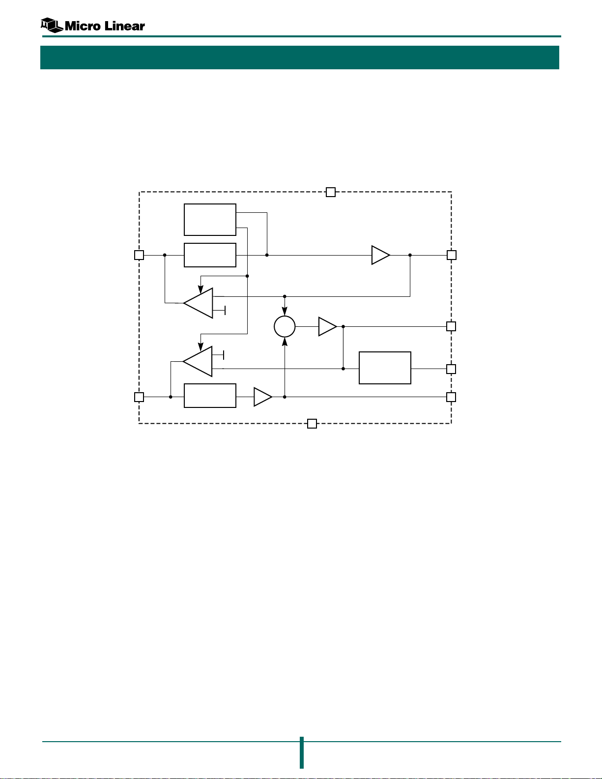
SIMPLIFIED BLOCK DIAGRAM
SYNC STRIP,
REFERENCE,
AND TIMING
ML6415
VCC
7
YIN
CIN
1
4
4TH – ORDER
FILTER
gM
1V
gM
4TH – ORDER
FILTER
1V
+
Σ
+
×2
×2
3
GND
×2
NOTCH,
GROUP
DELAY
6
2
5
YOUT
CVOUT
RF MOD
COUT
June, 2000 Datasheet 3
 Loading...