

Page 1

Chapter 1
1.1 General Information
1.1.01 General Information
The Microline 590 and Microline 591 are letter quality dot-matrix printers which utilize OKISMART paper
handling. Patented Okidata technology does away with the manual head gap adjustment. The Microline
590/591 actually "reads and learns" the media you feed in, then automatically adjusts the head gap to the
optimum distance. This auto-gapping process leads to longer printhead life.
An optional, user-installable Color Kit (coupled with a customer-provided color software package) allows
the printers to add impact to graphics, charts, transparencies and text presentations.
Additional options include the Bottom Feed Push Tractor, Cut-Sheet Feeder, Pull Tractor and Serial
Interface Board.
The Microline 590 is an 80 column printer.
The Microline 591 is a 132 column printer.
Okidata's extended two year limited warranty covers the parts, labor and printhead on both printers.
The following items are included with the printer:
OKISMART Typer - software which provides the flexibility for the Microline 590/591 to function like a
typewriter on checks, labels and envelopes.
OKISMART Panel - a utility program that lets you control selected printer functions from your personal
computer.
Scalable Fonts - 14 scalable fonts, available on diskette.
Note: The OkiSmart software includes three programs:
1. OkiSmart Control
2. OkiSmart Panel Emulator
3. OkiSmart Setup
Refer to the Printer Handbook for more information.
ML590/591 ( 96-02-07 )
Page 2

1.2 Physical Specifications
1.2 PHYSICAL SPECIFICATIONS
1.2.01 Dimensions
Note: Dimensions INCLUDE the platen knob, acoustic cover, and paper separator.
Microline 590
Width: 18.35 inches (466 millimeters)
Depth: 17.24 inches (438 millimeters)
Height: 6.52 inches (165 millimeters)
Microline 591
Width: 24.41 inches (620 millimeters)
Depth: 17.24 inches (438 millimeters)
Height: 6.52 inches (165 millimeters)
1.2.02 Printer Weight
Microline 590
16.5 pounds (6.5 kilograms)
Microline 591
19.8 pounds (8.9 kilograms)
ML590/591 ( 96-02-07 )
Page 3

1.3 Power Requirements
1.3 POWER REQUIREMENTS
1.3.01 Input Power
120 VAC: +5.5 / -15%
230/240 VAC: +10 / -14%
1.3.02 Power Consumption
Operating: 110 VA
Idle: 40 VA
1.3.03 Power Frequency
120 VAC: 60 Hz +/- 2%
230/240 VAC: 50/60 Hz +/- 2%
ML590/591 ( 96-02-07 )
Page 4

1.4 Environmental Conditions
1.4 ENVIRONMENTAL CONDITIONS
1.4.01 Acoustic Rating
Letter Quality Mode: 53 dBA
Quiet Mode: 50 dBA
1.4.01 Altitude
10,000 feet (3,050 meters)
1.4.03 Ambient Temperature and Relative Humidity (RH)
While operating: 41° to 104° F (5° to 40° C)
Operating humidity: 20% to 80% RH
While in storage: 14° to 122° F (-10° to 50° C)
Storage humidity: 5% to 95% RH
ML590/591 ( 96-02-07 )
Page 5
1.6 Operation Spec's - Print Speed and Character Matrix
1.6.01 Character Matrix Sizes
Table of Print Speed and Character Matrix
Mode LQ Utility High Speed Draft
Speed 120 (12 cpi) 360 (12 cpi) 450 (15 cpi)
Matrix (H x V) 29 x 18 9 x 17 7 x 17
Print Speed at Different CPI for the ML 590
Mode CPI CPS Horiz. DPI Vert DPI IPS
Utility 10 300 120 180 30
12 360 120 180 30
15 450 120 180 30
17.1 257 240 180 15
20 300 240 180 15
LQ 10 100 360 180 10
12 120 360 180 10
15 150 360 180 10
17.1 171 360 180 10
20 200 360 180 10
ML590/591 ( 96-02-07 )
Page 6

1.6.02 Characters Per Line
1.6.02 Characters Per Line
Microline 590
Characters Per
Line
Characters Per
Inch
Utility Letter Quality
80 10 164 65
96 12 161 65
120 15 148 65
136 17.1 96 65
160 20 95 65
Microline 591
Characters
Per Line
Characters
Per Inch
Utility Letter
Quality
136 10 105 40
163 12 96 40
204 15 88 40
233 17.1 59 40
272 20 59 40
ML590/591 ( 96-02-07 )
Page 7

1.6.03 Character Pitches
1.6.03 Character Pitches
5, 6, 8.5, 10, 12, 15, 17.1, 20
ML590/591 ( 96-02-07 )
Page 8

1.6.04 Character Sets
1.6.04 Character Sets
Standard ASCII
EPSON Character Set I & II
IBM Character Set I, II & All Characters
Foreign Character Substitution
International Character Sets
Code Page 850, 860, 863 and 865
Bar Code:
Code 39
UPC A
UPC E
EAN 8
EAN 13
Interleaved 2 of 5
Code 128
POSTNET
ML590/591 ( 96-02-07 )
Page 9

1.6.05 Printer Emulations
1.6.05 Printer Emulations
Note: The emulations are co-resident
Epson LQ
IBM XL 24E (AGM)
IBM Proprinter
ML590/591 ( 96-02-07 )
Page 10

1.6.06 Fonts
1.6.06 Fonts
Letter Quality
Courier
Letter Gothic
Prestige
Orator
Roman
Swiss
Draft
Utility
High Speed Draft (15 cpi)
Bar Code
Code 39
UPC A
UPC E
EAN 8
EAN 13
Interleaved 2 of 5
Code 128
POSTNET
ML590/591 ( 96-02-07 )
Page 11

1.6.07 Front Panel Switches
1.6.07 Front Panel Switches
Select Micro Feed Up / Down
Menu Mode Paper Park
Line Feed Pitch Selection
Form Feed Print Quality Selection
Top of Form Tear
Quiet
ML590/591 ( 96-02-07 )
Page 12

1.6.08 Graphics Resolution
1.6.08 Graphics Resolution
Graphics Resolution: 360 x 360 DPI maximum
ML590/591 ( 96-02-07 )
Page 13

1.6.09 Interface
1.6.09 Interface
Standard
Parallel
Optional
RS232C Serial
ML590/591 ( 96-02-07 )
Page 14

1.6.10 Line Feed Increments
1.6.10 Line Feed Increments
Fixed
6 lines per inch (lpi)[0.167 inch (4.23 millimeters)]
8 lines per inch (lpi)[0.125 inch (3.175 millimeters)]
Variable
n/60 inch
n/72 inch
n/180 inch
n/216 inch
n/360 inch
ML590/591 ( 96-02-07 )
Page 15

1.6.11 Line Feed Time
1.6.11 Line Feed Time
65 milliseconds 6 lines per inch (lpi)
6 milliseconds 8 lines per inch (lpi)
1 second 5.0 inches (Continuous paper feed rate)
ML590/591 ( 96-02-07 )
Page 16

1.6.12 Menu Mode
1.6.12 Menu Mode
Print: Prints the entire menu.
Group: Selects Group Function
Item: Selects Item
Set: Selects Item Value
Exit: Exits Menu Mode, Enters Select
ML590/591 ( 96-02-07 )
Page 17

1.6.13 Paper Feed Methods
1.6.13 Paper Feed Methods
Standard
Friction Feed (Top)
Rear Push Tractor (Rear)
Optional
Pull Tractor (Bottom)
Bottom Push Tractor (Bottom)
Single-Bin Cut Sheet Feeder (Top)
CSF 5000 - Narrow
CSF 5001 - Wide
ML590/591 ( 96-02-07 )
Page 18

1.6.14 Paper Feed Paths
1.6.14 Paper Feed Paths
Top Feed (Standard)
Rear Feed (Standard)
Bottom Feed (by using an Optional feed mechanism)
Special Features
Paper Park
Automatic Paper Loading
Forms Tear Off
ML590/591 ( 96-02-07 )
Page 19

1.6.15 Paper Loading
1.6.15 Paper Loading
Auto Loading (Top Feed)
Press LOAD switch for Bottom/Rear Feed
ML590/591 ( 96-02-07 )
Page 20

1.6.16 Paper Out Detection
1.6.16 Paper Out Detection
Distance from end of paper
Rear Feed: 0.5 inches (12.7 mm)
Bottom Feed: 0.5 inches (12.7 mm)
Top Feed: 0.5 inches (12.7 mm)
ML590/591 ( 96-02-07 )
Page 21

1.6.17 Paper Tear Capabilities
1.6.17 Paper Tear Capabilities
Forms Tear-0ff (sharp edge on access cover)
Metal Tear Bar (with optional bottom tractor unit)
ML590/591 ( 96-02-07 )
Page 22

1.6.18 Print Method
1.6.18 Print Method
Printhead Type
General Information
Impact: Dot Matrix
24 pin printhead
.0079 inch (.20 millimeter) diameter pins
Overheat Protection
When printhead temperature exceeds 110 degrees Celsius, the printer stops
bi-directional printing. Uni-directional printing begins.
If the temperature exceeds 115 degrees Celsius, printing stops.
Printing will resume when the printhead temperature drops below 115 degrees Celsius.
Note: Refer to Section Two for more information on printhead operation.
ML590/591 ( 96-02-07 )
Page 23

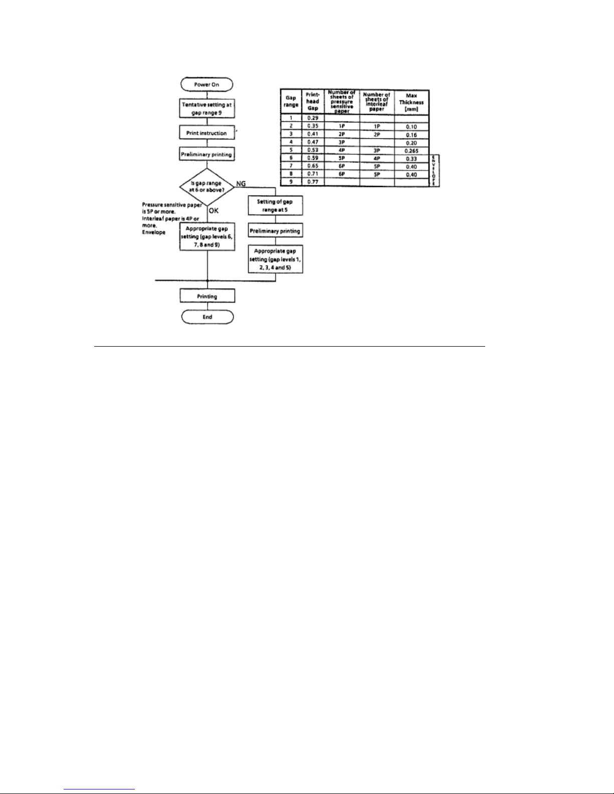
Printhead Gap Information
Printhead Gap Information
Three items factor into printhead gap information.
1. Printhead Gap Adjustment
This is a SERVICE ADJUSTMENT made by a technician.
It is covered in Section 3.3 of this Service Handbook.
The Adjustment measures 0.014, +/- 0.001 inches (0.35, +/- 0.03 mm).
2. Printhead Gap Adjust
This is a MENU ITEM in the SET-UP Group.
It fine tunes the automatic setting of the printhead gap.
The settings are 0, 1, and -1.
0 is the factory default.
Use 1 to darken print (if output is consistently light).
Use - 1 to lighten print (if output is consistently dark).
3. Gap Control
This is a MENU ITEM in each [Paper Feed] Group.
The Groups are REAR FEED, BOTTOM FEED, and TOP FEED.
Gap Control determines how the printhead gap is set.
The settings are listed below.
Auto Gap, Semi Auto Gap, 1, 2, 3, 4, 5, 6, 7, 8, 9
An explanation of each setting follows.
Auto Gap
This is the factory default.
Automatically determines paper thickness of the first page.
During single-sheet feed, each page's thickness is checked while
a job is printing.
Semi Auto Gap
Similar to Auto Gap.
Automatically determines paper thickness of the first page.
During single-sheet feed, each page's thickness IS NOT checked
"while" a job is printing
1, 2, 3, 4, 5, 6, 7, 8, 9
Used when the same paper is used ALL of the time.
Bypasses the automatic head gap adjustment.
1 is the narrowest gap setting.
9 is the widest gap setting.
ML590/591 ( 96-02-07 )
Page 24
ML590/591 ( 96-02-07 )
Page 25

1.6.19 Print Modes
1.6.19 Print Modes
Letter Quality
Utility
High Speed Draft
ML590/591 ( 96-02-07 )
Page 26

1.6.20 Print Speed
1.6.20 Print Speed
Table of Print Speed and Character Matrix
Mode LQ Utility High Speed Draft
Speed 120 (12 cpi) 360 (12 cpi) 450 (15 cpi)
Matrix (H x V) 29 x 18 9 x 17 7 x 17
ML590/591 ( 96-02-07 )
Page 27

1.7 Paper Specifications
1.7 PAPER SPECIFICATIONS
CAUTION: Use Bottom Feed and/or optional Pull Tractor for card stock and labels.
1.7.01 Types
Card Stock
Weight: 120 lbs. (450 g/m2) Maximum
Width: Microline 590 5 to 8 inches (12.7 to 20.3 centimeters)
Microline 591 5 to 14 inches (12.7 to 35.6 centimeters)
Length: 3 to 17 inches (7.62 to 43.18 centimeters)
Thickness: .017 inches (0.44 millimeters)
Paper Feed Path: Bottom
Printhead Gap
Information: Refer to the Printhead Gap Information, Section 1.6(
)
Continuous Form
Weight:
Single Part 12 - 24 lb. (45 to 90 g/m2)
Multi-Part
Carbonless 9 - 11 lb. (35 to 40 g/m2)
Multi-Part,
Interleaf
Paper 10 - 12 lb. (38 to 45 g/m2)Carbon 9 lb. (35 g/m2)
Width: Microline 590 3.5 to 10.5 inches (8.8 to 26.6 centimeters)
Microline 591 3.5 to 16.5 inches (8.8 to 41.9 centimeters)
Length: 3 to 17 inches (7.62 to 43.18 centimeters)
Thickness: 0.014 inches (0.36 millimeters) Rear Feed
0.017 inches (0.44 millimeters) Bottom Feed
Paper Feed Path: Rear or Bottom
Printhead Gap
Information: Refer to the Printhead Gap Information, Section 1.6 (
)
Cut Sheet
Weight: 12 to 24 lbs. (45 to 90 g/m2)
Width: 7.2 to 14.3 inches (18.3 to 36.3 centimeters)
Width: Microline 590 7.2 to 8.5 inches (18.2 to 21.5 centimeters)
Microline 591 7.2 to 14.3 inches (18.2 to 36.3 centimeters)
Length: 3 to 17 inches (7.62 to 43.18 centimeters)
Thickness: 0.014 inches (0.325 millimeters) Maximum
Paper Feed Path: Top
Printhead Gap
Information: Refer to the Printhead Gap Information, Section 1.6. (
)
Envelopes
Weight: 24 lbs. (90 g/m2) Maximum
Size:
Single Feed
Minimum: 6.5 x 3.6 inches (16.5 x 9.1 centimeters)
Maximum: 9.5 x 4.1 inches (24.1 x 10.4 centimeters)
Continuous
Non-overlap type
Thickness: .014 inches (.325 millimeters) Maximum
ML590/591 ( 96-02-07 )
Page 28

Paper Feed Path: Bottom
Printhead Gap
Information: Refer to the Printhead Gap Information, Section 1.6.
Labels
Weight: N/A
Width: Microline 590 3.5 to 10.5 inches (8.8 to 26.6 centimeters)
Microline 591 3.5 to 16.5 inches (8.8 to 41.9 centimeters)
Length: 3 to 17 inches (7.62 to 43.18 centimeters)
Thickness: .011 inches (0.28 mm) Maximum (including backing)
Paper Feed Path: Bottom
Printhead Gap
Information: Refer to the Printhead Gap Information, Section 1.6. (
)
CAUTION: Use Bottom Feed and/or optional Pull Tractor for card stock and labels.
Transparency
Note: Roller marks may mar the transparency under high temperature/
high humidity conditions.
Weight: 12 to 24 lbs. (45 to 90 g/m2)
Width: Microline 590 7.2 to 8.5 inches (18.2 to 21.5 centimeters)
Microline 591 7.2 to 14.3 inches (18.2 to 36.3 centimeters)
Length: 3 to 17 inches (7.62 to 43.18 centimeters)
Thickness: 0.14 inches (0.36 millimeters)
Paper Feed Path: Top
Printhead Gap
Information: Refer to the Printhead Gap Information, Section 1.6.(
)
1.7.02 Length
Note: The recommended length is specific to paper type.
Rear Feed
Minimum 3 inches (7.62 centimeters)
Maximum 17 inches (43.18 centimeters)
Bottom Feed
Minimum 3 inches (7.62 centimeters)
Maximum 17 inches (43.18 centimeters)
Top Feed
Minimum 3 inches (7.62 centimeters)
Maximum 17 inches (43.18 centimeters)
1.7.03 Number of Copies
Original + 4Interleaf
Original + 4Carbonless
Original Cut Sheet
1.7.04 Thickness
0.014 inches / 0.36 mm Maximum Thickness, Rear Feed
0.017 inches / 0.44 mm Maximum Thickness, Bottom Feed
1.7.05 Weight
Note: The recommended weight is specific to paper type.
Minimum: 9 lb. (35 g/m2)
Maximum: 24 lb. (90 g/m2)
1.7.06 Width
Note: The recommended width is specific to paper type.
Paper
Microline 590
ML590/591 ( 96-02-07 )
Page 29

Minimum: 3.5 inches (8.8 centimeters)
Maximum: 10.5 inches (26.6 centimeters)
Microline 591
Minimum: 3.5 inches (8.8 centimeters)
Maximum: 16.5 inches (41.9 centimeters)
Printing Area
Microline 590 8 inches Maximum
Microline 591 13.6 inches Maximum
ML590/591 ( 96-02-07 )
Page 30

1.8 Memory Specifications
1.8 MEMORY SPECIFICATIONS
1.8.01 EEPROM
1 Kbit serial EEPROM (used to store Menu data)
1.8.02 ROM
"Older" Configuration
1 Mbit, Character Generator ROM (located on main control board, 05C)
1 Mbit, Printer Control EPROM (located on main control board, 05D)
"New" Configuration
4 Mbit (located on main control board, 05D)
1.8.03 RAM
Receive Buffer Size is selected through the Menu.
Settings are: 64 K, 32 K, 1 line
ML590/591 ( 96-02-07 )
Page 31

1.9 Consumables
1.9 CONSUMABLES
1.9.01 Ribbon
CAUTION: Using a non-Okidata ribbon may damage the printhead and void any
warranties.
Material
Cartridge Fabric
Types
Black Ribbon
Color Ribbon
Magenta
Yellow
Cyan
Black
Life (On average, at 10 characters per inch, Utility Mode)
Black Ribbon 4 million characters
Color Ribbon
Magenta 1.5 million characters
Yellow 0.8 million characters
Cyan 1.5 million characters
Black 1.5 million characters
ML590/591 ( 96-02-07 )
Page 32

1.10 Options
1.10 OPTIONS
Cut Sheet Feeders ...... (
)
Pull Tractor Kit ............ (
)
Color Ribbon Kit ..........(
)
Bottom Push Tractor .... (
)
Serial Interface ............(
)
Roll Paper Stand .........(
)
Bitstream Facelift 2.0 ... (
)
OKIsmart Typer Utility .. (
)
OKIsmart Panel Utility .. (
)
ML590/591 ( 96-02-07 )
Page 33

1.10.01 Cut Sheet Feeders
1.10.01 Cut Sheet Feeders
The CSF-5000 is a narrow feeder for the Microline 590.
Single Bin with envelope capability
Paper Width: 7.2" to 8.5" (18.3 cm to 36.3 cm)
Paper Length: 10.1" to 14" (25.6 cm to 35.6 cm)
Capacity: 170 sheets (16 lb.), 100 sheets (20 lb.)
The CSF-5001 is a wide feeder for the Microline 591.
Single Bin with envelope capability
Paper Width: 7.2" to 14.3" (18.3 cm to 36.3 cm)
Paper Length: 10.1" to 14" (25.6 cm to 35.6 cm)
Capacity: 170 sheets (16 lb.), 100 sheets (20 lb.)
ML590/591 ( 96-02-07 )
Page 34

1.10.02 Pull Tractor Kit
1.10.02 Pull Tractor Kit
Note: The Pull Tractor Kit (P/N 70023001) is a narrow feeder for the Microline 590.
The Pull Tractor Kit (P/N 70023201) is a wide feeder for the Microline 591.
Bottom Feed
Rear Feed (For Push/Pull Operation)
Paper Types: Continuous Feed and Labels
ML590/591 ( 96-02-07 )
Page 35

1.10.03 Color Ribbon Kit
1.10.03 Color Ribbon Kit
Includes:
Color mechanism
Color Ribbon
End user installable
ML590/591 ( 96-02-07 )
Page 36

1.10.04 Bottom Push Tractor Kit
1.10.04 Bottom Push Tractor Kit
Note: The Bottom Push Tractor Kit (P/N 70022901) is a narrow feeder for the Microline
590. The Bottom Push Tractor Kit (P/N 70023101) is a wide feeder for the
Microline 591.
Bottom Feed
Paper Type: Continuous Feed
Includes: Stand and Metal Tear B
ML590/591 ( 96-02-07 )
Page 37

1.10.05 Serial Interface
1.10.05 Serial Interface
Super-Speed 19.2K RS-232C
Ready/Busy/X-On/X-Off Protocols
Can be configured through the Menu or OKISmart Utility Program
ML590/591 ( 96-02-07 )
Page 38

1.10.06 Roll Paper Stand
1.10.06 Roll Paper Stand
Adapts printer for use with roll-type paper (Model 590 only)
Includes: Stand, Support, Cord and DIN plug for connection to printer
ML590/591 ( 96-02-07 )
Page 39

1.11 Reliability
1.11 RELIABILITY
1.11.01 Mean Time Before Failure (MTBF)
Approximately 6,000 hours: 25% duty cycle / 35% page density
1.11.02 Mean Time To Repair (MTTR)
Approximately 15 minutes to major sub-assembly level
1.11.03 Printer Life
Approximately 16,000 hours of power-on time: 25% duty cycle / 35% page density
1.11.04 Printhead Life
Average 200 million characters in 10 cpi utility mode @ normal 25% duty,35% page
density
1.11.05 Ribbon Life
Black: Approximately 4 million characters
Color:
Black: Approximately 1.5 million characters
Cyan: Approximately 1.5 million characters
Magenta: Approximately 1.5 million characters
Yellow: Approximately 0.8 million characters
1.11.06 Warranty (Limited)
Two years, parts and labor
1.11.07 Service
Authorized Okidata Service Centers
ML590/591 ( 96-02-07 )
Page 40

Chapter 2
2.1 Electrical Operation
2.1 ELECTRICAL OPERATION
2.1.01 General Information
The printers is made of the following electrical components.
Main Control Board
Power Supply Assembly
Operator Panel
Space Motor / Line Feed Motor
Printhead
ML590/591 ( 96-02-07 )
Page 41
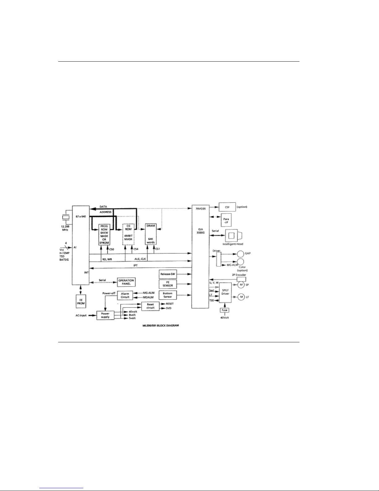
2.1.02 Main Control Board
2.1.02 Main Control Board
The main control board is made up of the microprocessor, peripheral circuits, drive circuits,
sensors and interface connectors.
The power to the main control board is supplied by the power supply assembly through a wire
harness. The power to other electrical parts, such as the line feed motor, space motor and
printhead, is supplied by the power supply assembly through the connectors on the main control
board.
Microprocessor (MPU)
Location 04D: 67X640
16 bit MPU, using CMOS technology.
The MPU contains a 20 bit address bus, a 16 bit data bus.
The MPU can access 1 Mbyte of program memory space and 1 Mbyte of data
memory space.
The microprocessor controls the entire printer by executing the control program
through the LSI and the driver circuit.
ML590/591 ( 96-02-07 )
Page 42
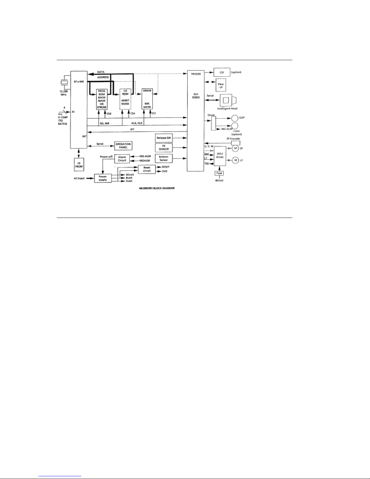
Block Diagram
ML590/591 ( 96-02-07 )
Page 43
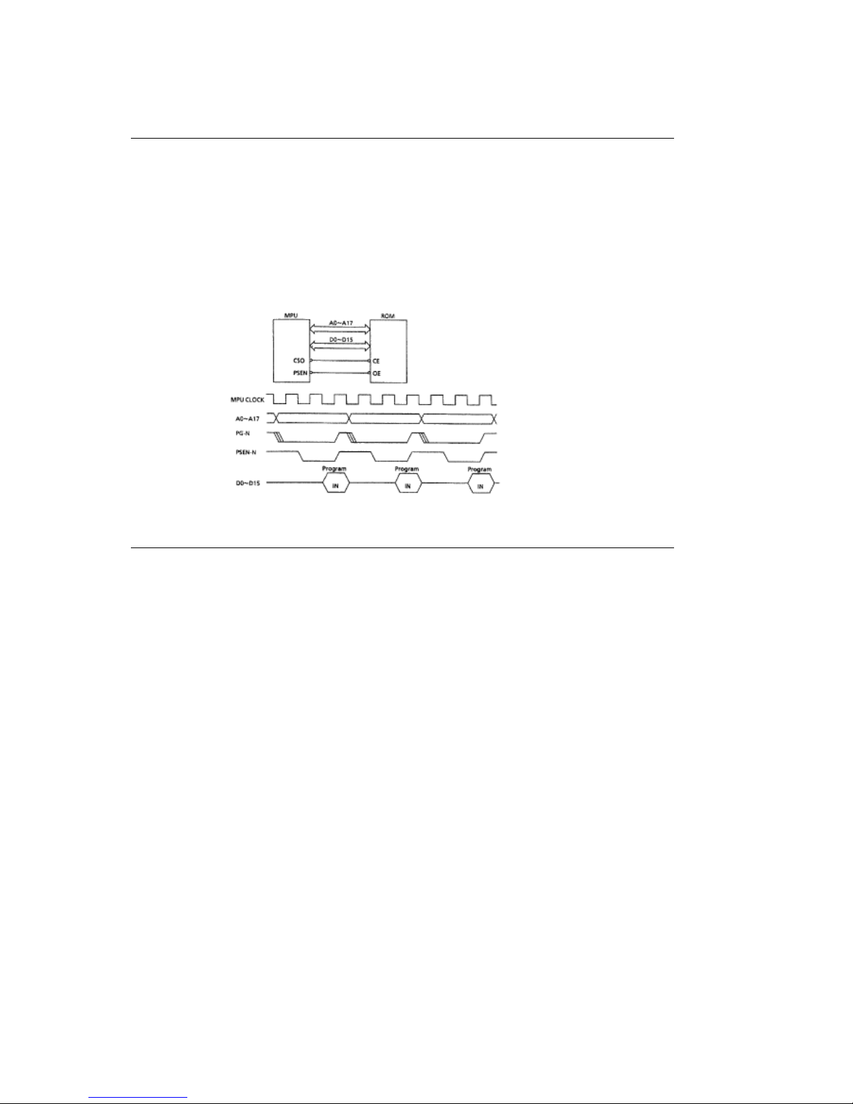
Program ROM
Program ROM
Location 05D: 27C1024
This 64k x 16 bit (Mbit) EPROM contains the control program for the printer. The MPU executes
the instructions contained in this program.
The Program ROM is assigned to the program memory area of the MPU and instructions are
fetched by the PSEN signal of the MPU.
ML590/591 ( 96-02-07 )
Page 44
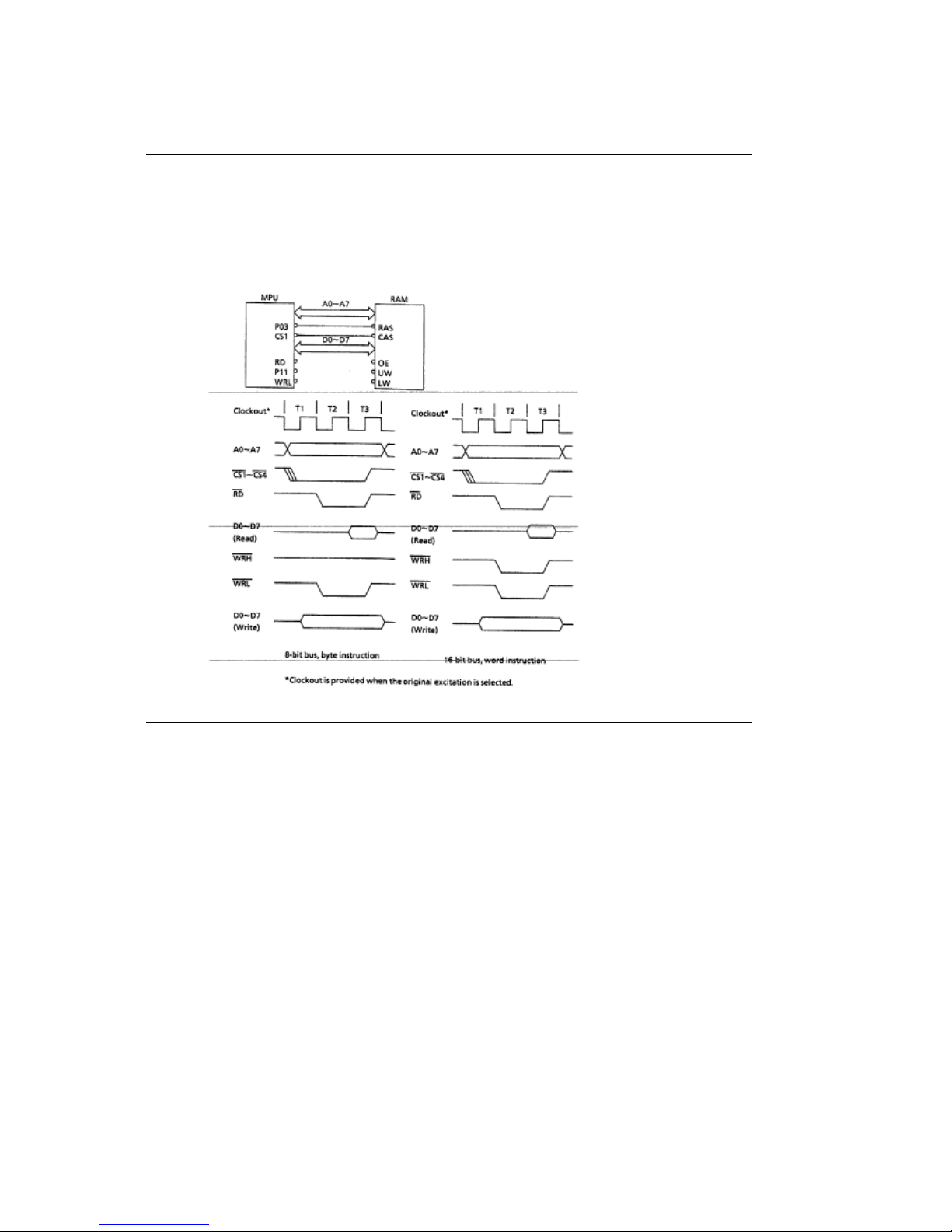
RAM
RAM
Location 05E: 511664Z.
The RAM is CMOS dynamic RAM with 65,536 words x 16-bit configuration, and is used as a
receive buffer, print buffer and work buffer.
ML590/591 ( 96-02-07 )
Page 45
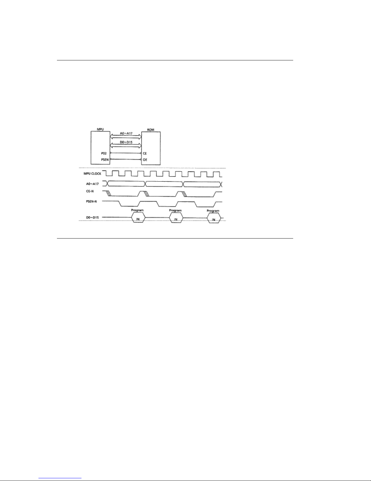
Character Generator ROM (CG ROM)
Character Generator ROM (CG ROM)
Location 05C: 27C4096.
This 256k x 16 bits (4 Mbit) masked EPROM contains the character data for the various fonts.
The CG ROM is assigned to the program memory area of the MPU. The data is accessed by the
PSEN signal of the MPU.
ML590/591 ( 96-02-07 )
Page 46
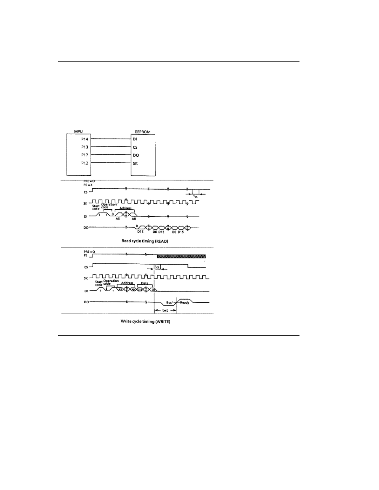
Electrically Erasable Programmable ROM (EEPROM)
Electrically Erasable Programmable ROM (EEPROM)
Location 03C: 93CS46.
The EEPROM is a CMOS serial I/O type memory which is capable of electrically erasing and
writing 1,024bits.
The EEPROM contains the menu data and the head drive time correction data.
ML590/591 ( 96-02-07 )
Page 47

LSI
LSI
Location 02D: MSM(79V035).
Detects the output of the two-phase sensor on the DC space motor to control the motor drive
phase.
Transmits and receives serial data to and from the printhead based on the dot timing (which is
derived from the space motor speed).
Controls the external interface. The LSI is connected to the MPU.
ML590/591 ( 96-02-07 )
Page 48
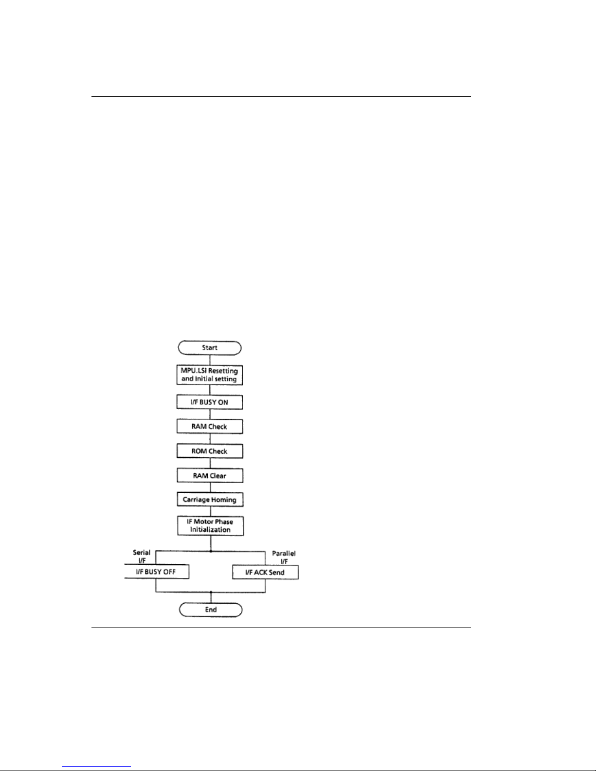
2.1.03 Initialization
2.1.03 Initialization
This printer is initialized when the printer is powered on or when the I-PRIME-N signal is input
from the host via the parallel interface.
Printer Initialization occurs as listed below.
The RST-N signal is output from the Reset circuit to reset the MPU and LSIs.
The program is executed and the LSIs are reset by the MPU via IORST-N.
Note: A Reset operation initiated by I-PRIME does not reset the MPU.
The program sets the LSI (02D) mode, checks the memory (ROM/RAM), then executes carriage
homing and determines the phase of the line feed motor.
Finally, the program establishes the interface signals (P-I/F: ACK-P signal sending, and S-I/F:
BUSY-N signal off) and lights the SELECT lamp to indicate that the printer is in the ON-LINE
state.
ML590/591 ( 96-02-07 )
Page 49
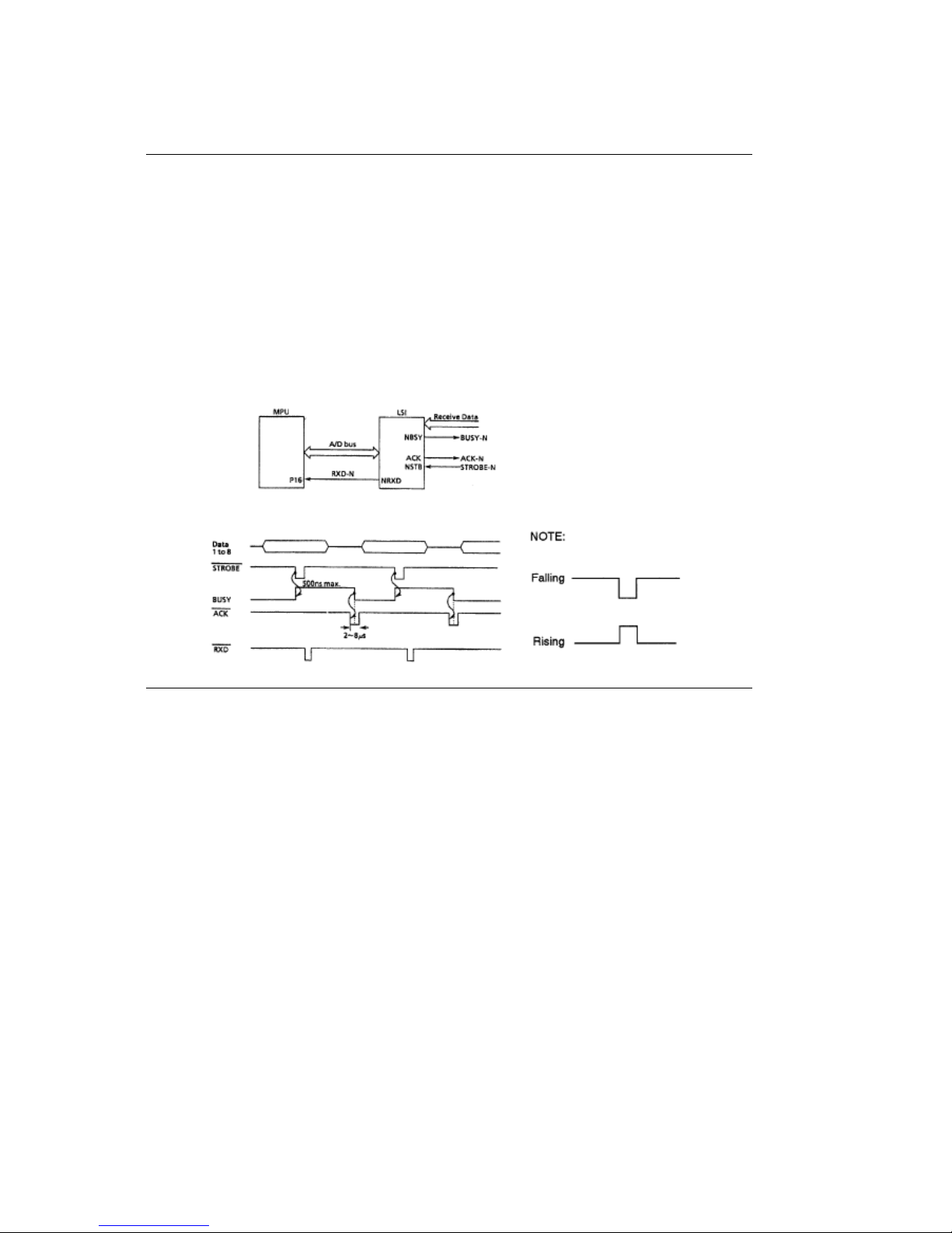
2.1.04 Parallel Interface Control
2.1.04 Parallel Interface Control
The parallel data input from the host to the interface LSI is latched to the internal register by the
falling edge of the STROBE-N signal.
The LSI sets the BUSY-N signal to inform the host that the data is being processed. The LSI also
outputs the RXD-N signal to inform the MPU of data reception. The data is read upon receiving
the RD-N signal from the MPU.
When the data processing is complete, the BUSY-N signal is disabled and the ACK-N signal is
sent to request the next data. When the buffer is full and reception is not desired, the BUSY
signal is sent to request data transmission be stopped.
ML590/591 ( 96-02-07 )
Page 50

2.1.05 Print Control
2.1.05 Print Control
The print data is transmitted as serial data from the LSI to the control circuit and the driver
contained in the printhead.
After the data is printed, the sensor analog circuit controlling each pin returns the pin stroke data
to the MPU. The MPU will make an automatic head gap adjustment. This feedback system sets
the optimum drive time for each pin in order to maintain high print quality.
ML590/591 ( 96-02-07 )
Page 51
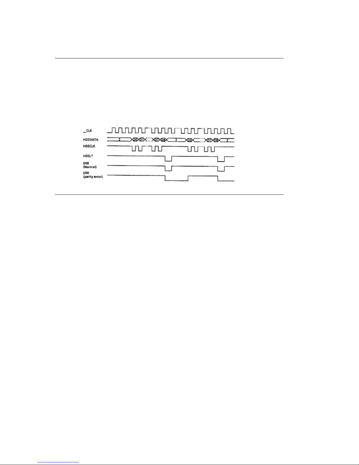
LSI/Printhead Interface
LSI/Printhead Interface
The connection between the LSI and the printhead is made with the bi-directional serial data bus.
The LSI transmits the print data as serial data to the logic circuit of the printhead. The printhead
returns serial data from the printhead sensor analog circuit to the LSI. This information is used to
determine the optimum drive time for the next print request.
The logic circuit of the printhead signals the LSI if a parity error is detected in the print data.
ML590/591 ( 96-02-07 )
Page 52
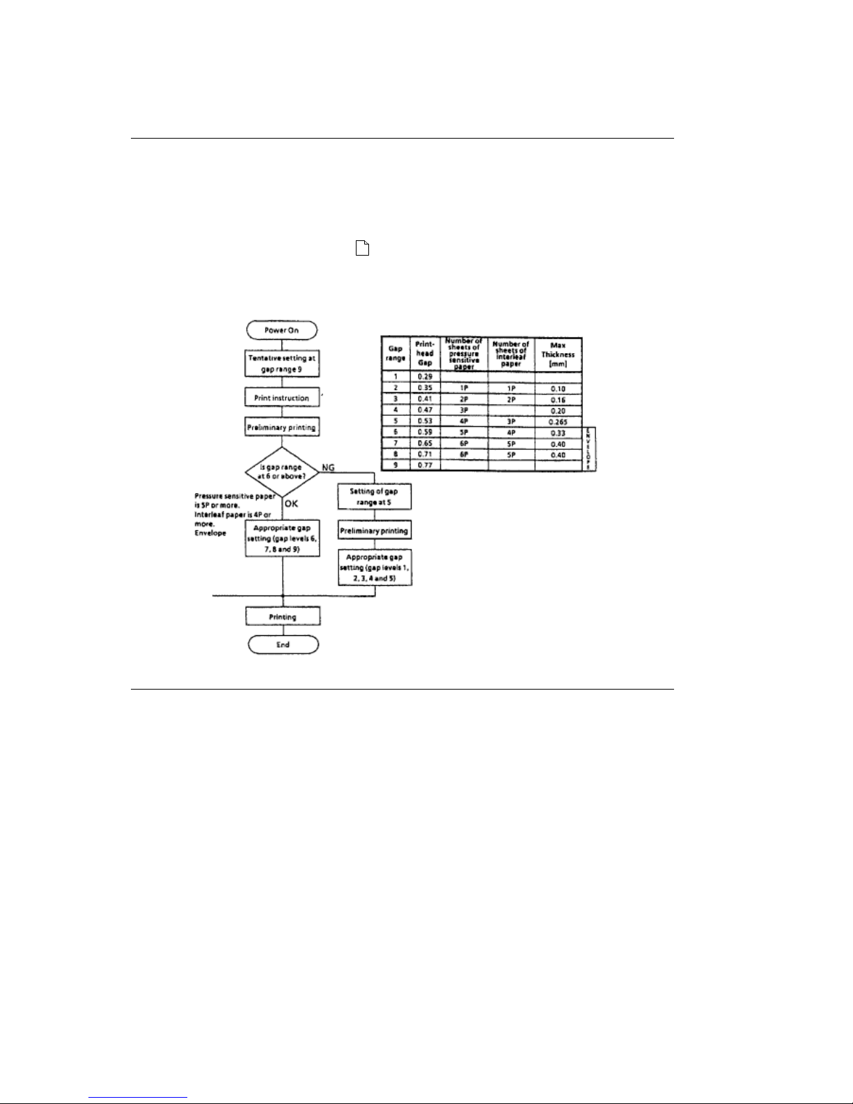
Gap Adjust Control
Gap Adjust Control
The Gap Adjust LSI receives stroke length information for all of the printhead pins from the
sensor analog circuit. The Gap Adjust LSI then sets the optimum printhead gap for the printing
medium.
Note: Refer to Section 2.2.03(
) for a description of the mechanical process.
All values in the chart are in millimeters
ML590/591 ( 96-02-07 )
Page 53
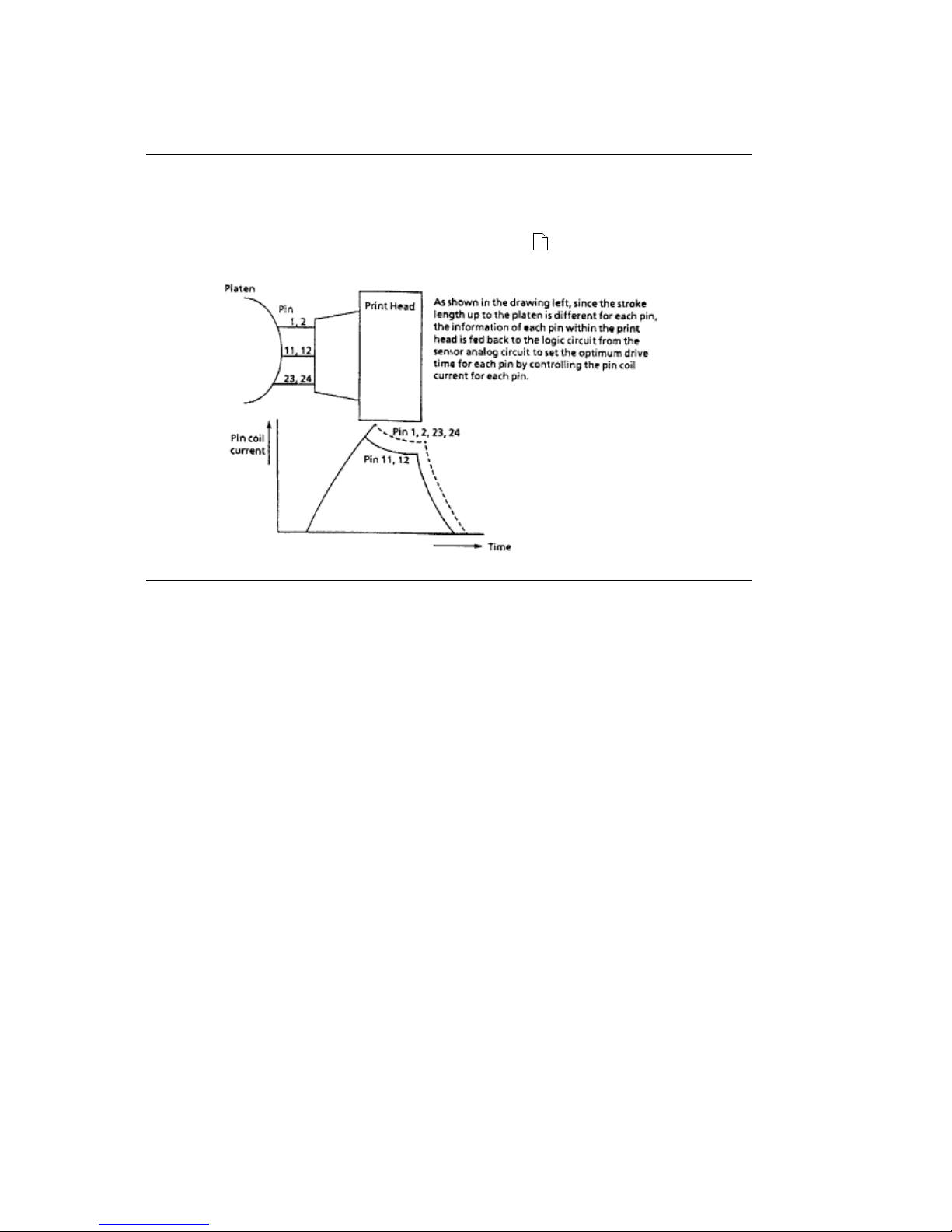
Print Compensation Control
Print Compensation Control
The printhead compensates for the shape of the platen as shown below.
Note: Refer to Section 2.1.08 - Head Drive Time (
)
ML590/591 ( 96-02-07 )
Page 54
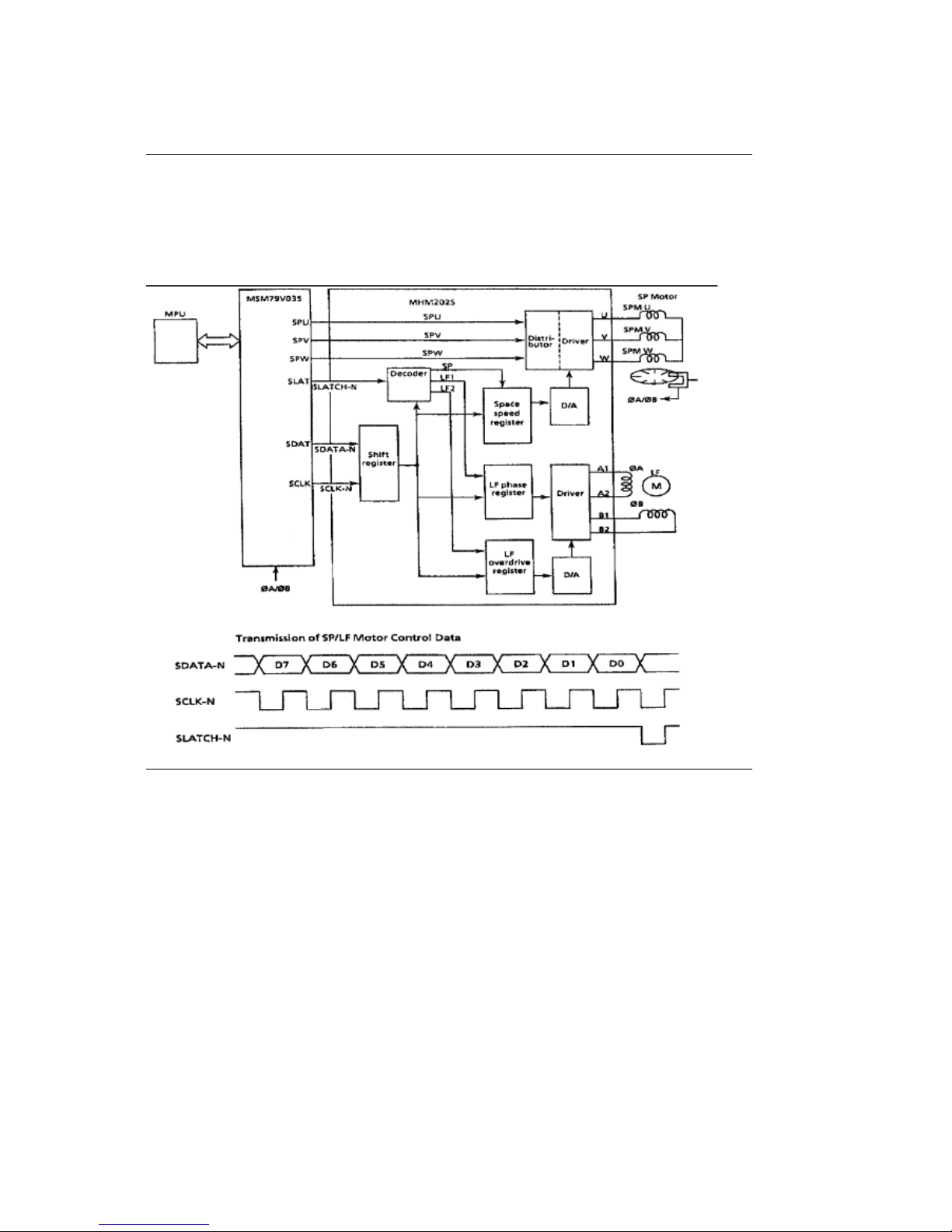
2.1.06 Space and Line Feed (SP/LF) Motor Control
2.1.06 Space and Line Feed (SP/LF) Motor Control
The LSI (Location 02D: MSM79V035) generates the space motor and the line feed motor control
signals according to commands received from the MPU. These signals are sent to the SP/LF
motor driver.
ML590/591 ( 96-02-07 )
Page 55
Line Feed Motor Control
Line Feed Motor Control
The SP/LF motor driver (Location 5A: MHM2025) drives the line feed motor in two-phase bipolar,
based on the phase changeover data output from the LSI.
The serial data from the LSI (02D:MSM79V035) is processed by a register contained in the
SP/LF motor driver to measure the overdrive time and to change the phase.
ML590/591 ( 96-02-07 )
Page 56
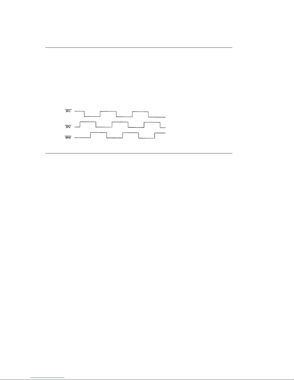
Space Motor Control
Space Motor Control
The SP/LF motor driver (Location 5A: MHM2025) drives the three-phase brushless motor. Motor
movement is based on the phase signal (SPU,SPV and SPW) and the speed instruction data
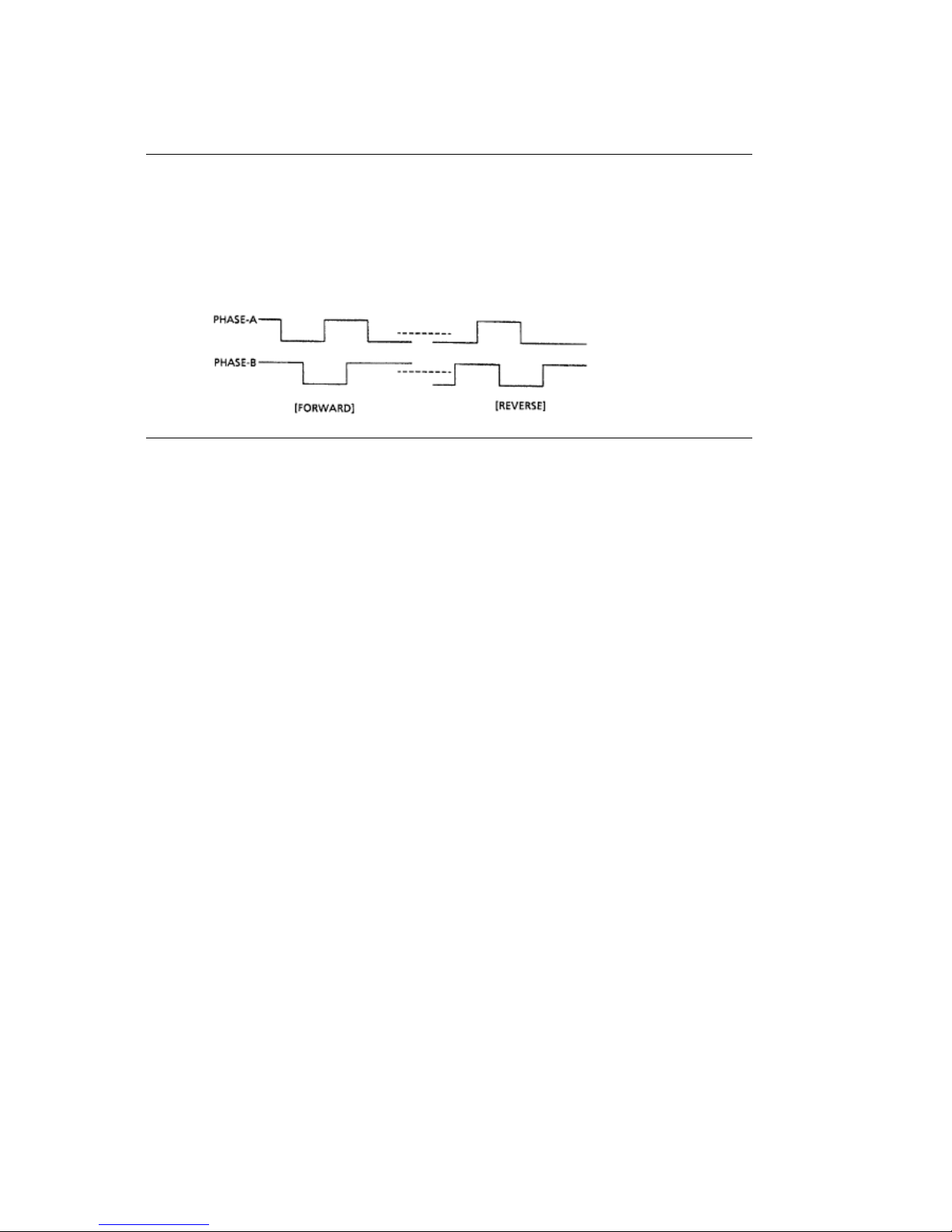
from the LSI. The MPU can identify the current speed of the space motor by measuring the pulse
width of the output (Phase A, Phase B) of the encoder disk sensor.
After comparing the target speed for each print mode with the actual speed, the motor is
accelerated or decelerated to maintain the desired speed for each print mode.
ML590/591 ( 96-02-07 )
Page 57

Encoder Disk
Encoder Disk
As the space motor operates, the encoder disk spins. When the encoder disk interrupts the photo
sensors, the signals Phase A and Phase B are generated. The LSI (Location 02D: MSM79V035)
divides these edge pulse signals (the frequency division is based on the selected print pitch) to
generate the signal IPT. The IPT signal provides dot-on timing and carriage position detection
timing.
ML590/591 ( 96-02-07 )
Page 58
2.1.07 Operation Panel
2.1.07 Operation Panel
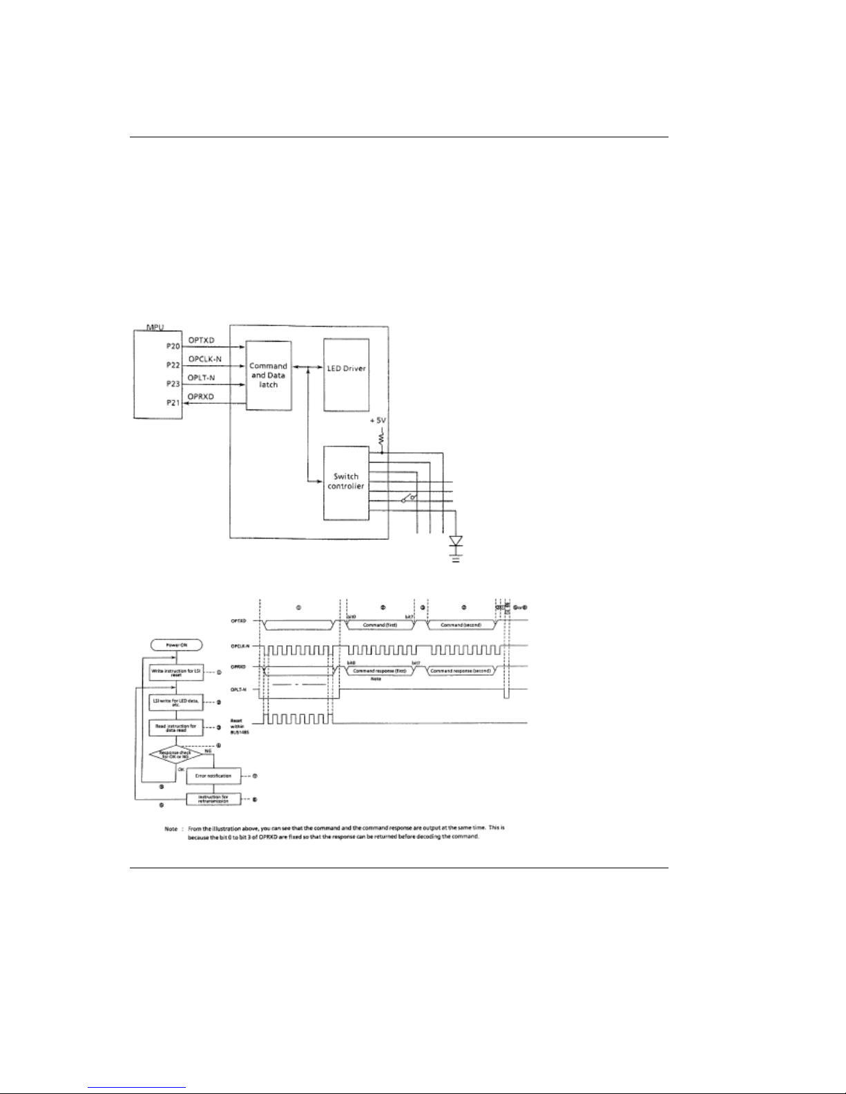
The Serial I/O Port (Ports 20 - 23) of the MPU reads the operation panel switch data from the
operation panel control LSI (Location IC1: BUS148S). The Serial I/O Port also outputs LED data
to the operation panel control LSI.
A two byte (15 bits +1 parity bit (even parity)) command (OPTXD) is transmitted from the MPU to
the operation panel LSI in synchronization with the OPCLK signal. Once the LSI decodes the
command, the command must pass a command code check and have no parity errors. Then, the
specified I/O control will return the two byte command response to the MPU.
ML590/591 ( 96-02-07 )
Page 59
2.1.08 Alarm Circuit
2.1.08 Alarm Circuit
Driver Circuit Alarm Processing
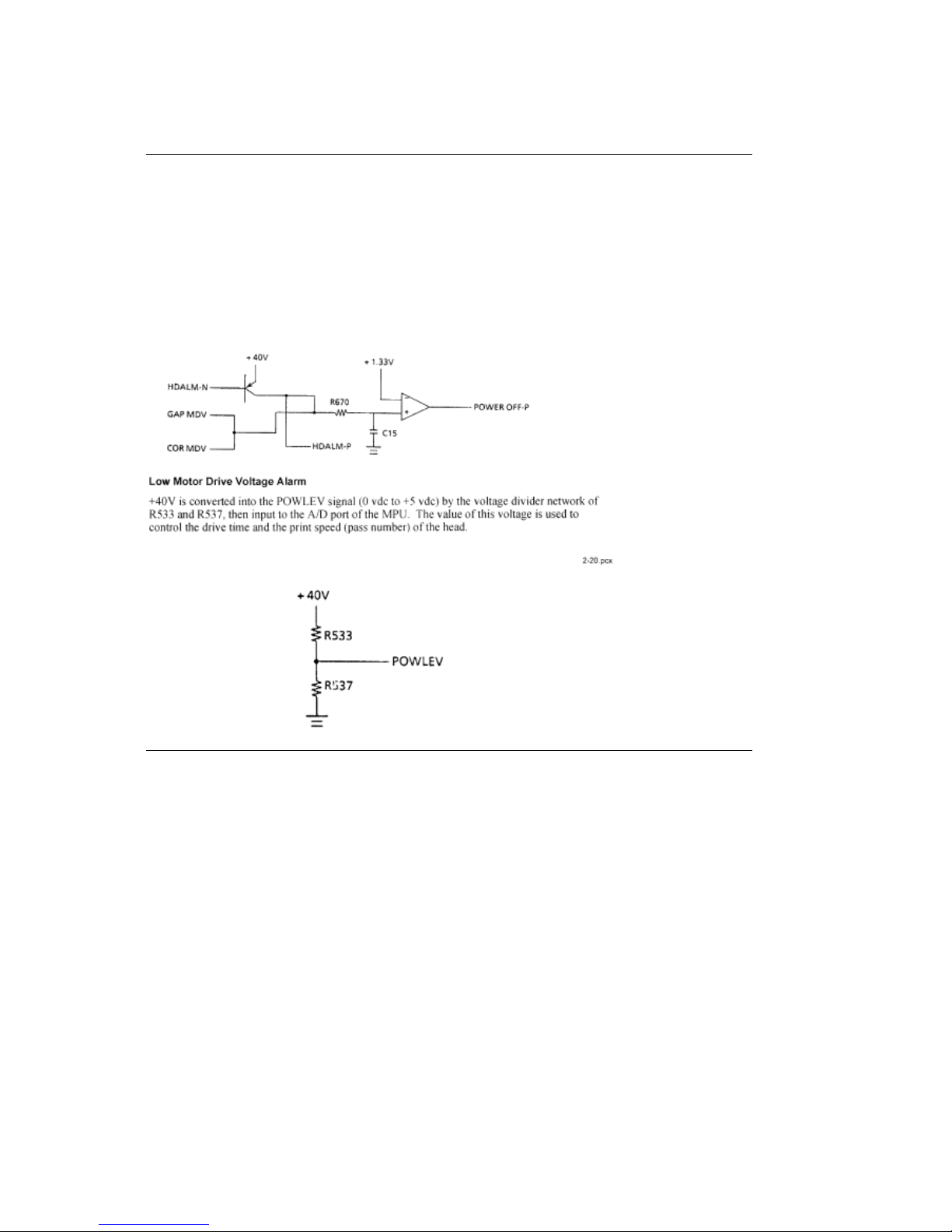
The printhead driver output, the head gap magnet output and the color ribbon magnet drive signal
are monitored at R670 and C15, and the POWER OFF-P signal is output by the comparator
(Location 01A: IC2901) when driven for more than the specified time. This signal becomes the
ALM signal. The ALM signal is sent to the power supply board and causes the DC voltages to be
turned off.
ML590/591 ( 96-02-07 )
Page 60

Head Drive Time
Head Drive Time
The head drive time is modified to compensate for the amount of the voltage drop of the
POWLEV signal. By monitoring the voltage drop every 500 microseconds, the MPU is able to
control and maintain the impact necessary for each printhead pin.
#####
ML590/591 ( 96-02-07 )
Page 61

Print Speed
Print Speed
Actual Voltage (+40 vdc) Passes
Required
Relative Print Speed
+34 vdc or greater 1 100%
+32 vdc to +34 vdc 1 Approximately 85%
+30 vdc to +32 vdc 1 Approximately 50%
+30 vdc or less 2 Less than 50%
ML590/591 ( 96-02-07 )
Page 62
Head Overheat Alarm Processing
Head Overheat Alarm Processing
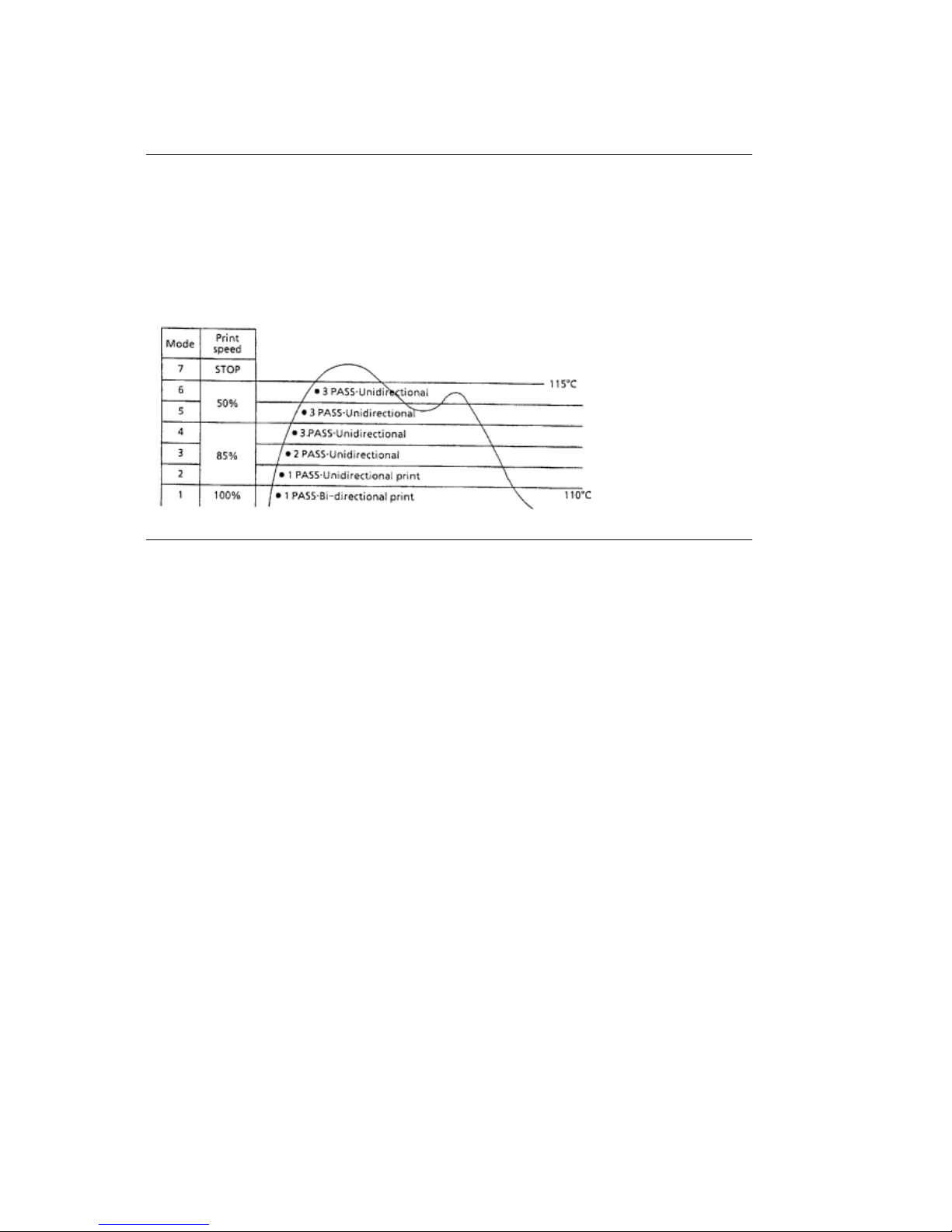
Two thermistors are used to monitor the printhead temperature. One is contained in the printhead
and the other in the printhead driver. The voltage of the TSD signal is monitored at the MPU A/D
port to control the pass number and print method (unidirectional / bi-directional) at each of seven
levels. If the printhead temperature exceeds 110 degrees Celsius, the printer will switch to
unidirectional print. If the temperature exceeds 115 degrees Celsius, printing will stop. Once the
printhead cools, printing will resume.
ML590/591 ( 96-02-07 )
Page 63
2.1.09 Power Supply Circuit
2.1.09 Power Supply Circuit
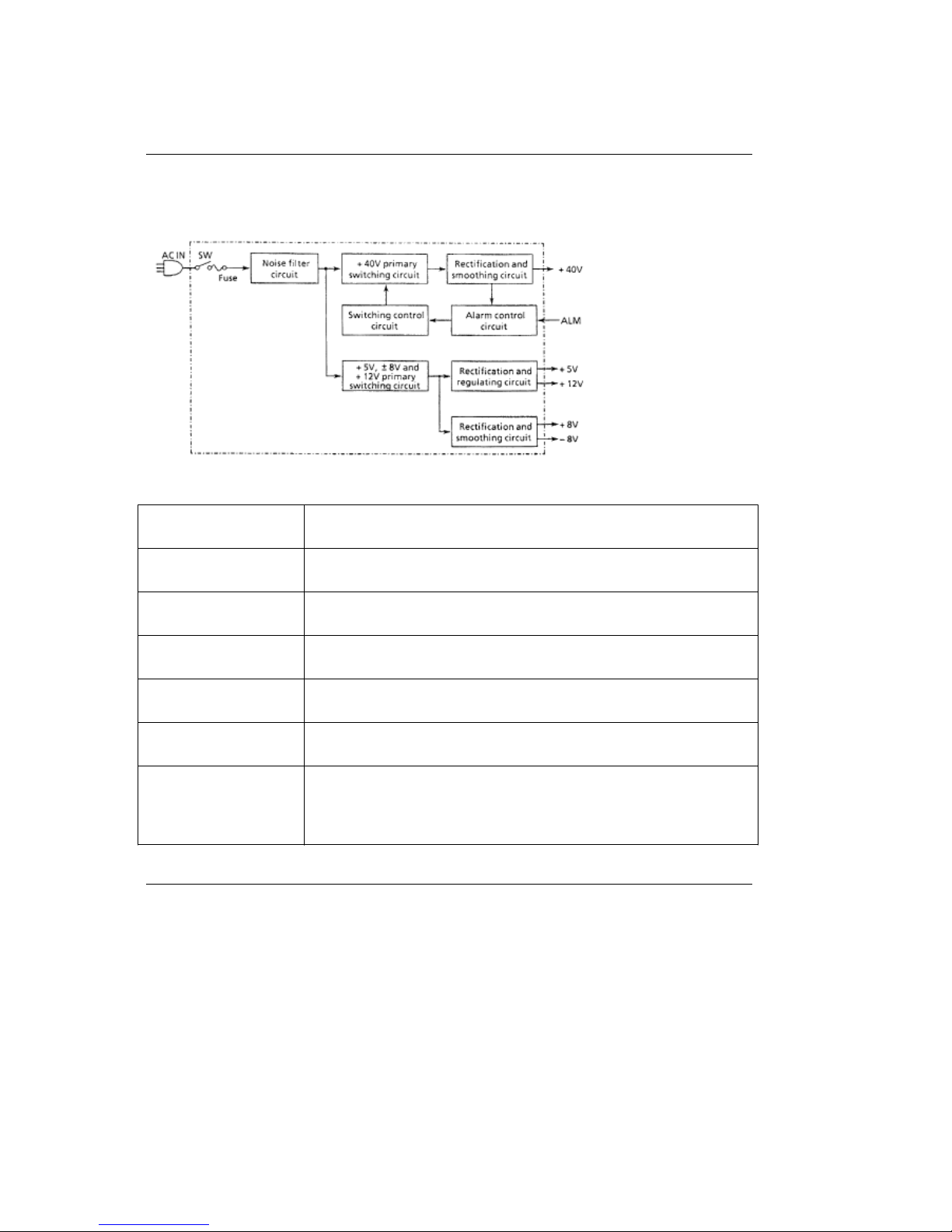
The switching type power supply circuit supplies the +5 vdc, +/-8 vdc, +12 vdc and +40 vdc.
Table of Output Voltages
Voltage / Signal Purpose
+5 vdc IC logic levels LED drive voltages
+8 vdc Serial interface line voltage comparator IC
-8 vdc Serial interface line voltage
+12 vdc Printhead analog circuit
+40 vdc Printhead space motor and line feed motor drive voltage
ALM Output from the main control board upon detection of an
abnormality in the printhead head gap or color ribbon drive circuits.
This signal will cause all DC voltages to be turned off.
ML590/591 ( 96-02-07 )
Page 64

2.2 Mechanical Operation
2.2 MECHANICAL OPERATION
The following section explains the mechanical operation of the printer.
Spacing Mechanism .................................... (
)
Head Gap Mechanism .............................. (
)
Ribbon Drive Mechanism .......................... (
)
Line Feed Mechanism ................................ (
)
Paper Detect Mechanism ......................... (
)
Support Protector Mechanism ................. (
)
Automatic Paper Load ............................... (
)
Paper Park ..................................................... (
)
ML590/591 ( 96-02-07 )
Page 65
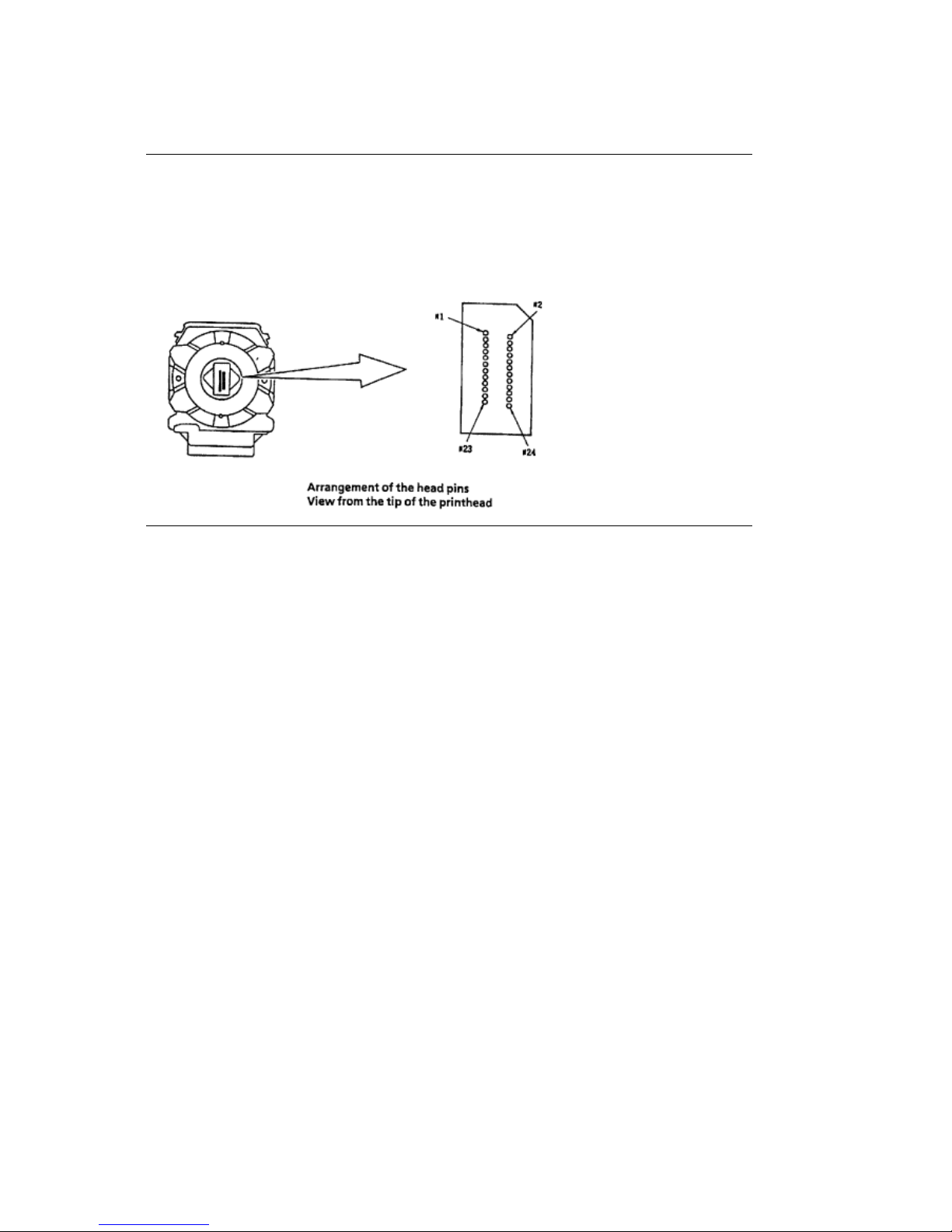
2.2.01 Printhead Mechanism
2.2.01 Printhead Mechanism
The printhead is a spring charged 24-pin printhead. It is attached to the carriage, which moves
parallel to the platen. Electrically, the printhead is controlled by the main control board via the
carriage cable and the space motor.
ML590/591 ( 96-02-07 )
Page 66
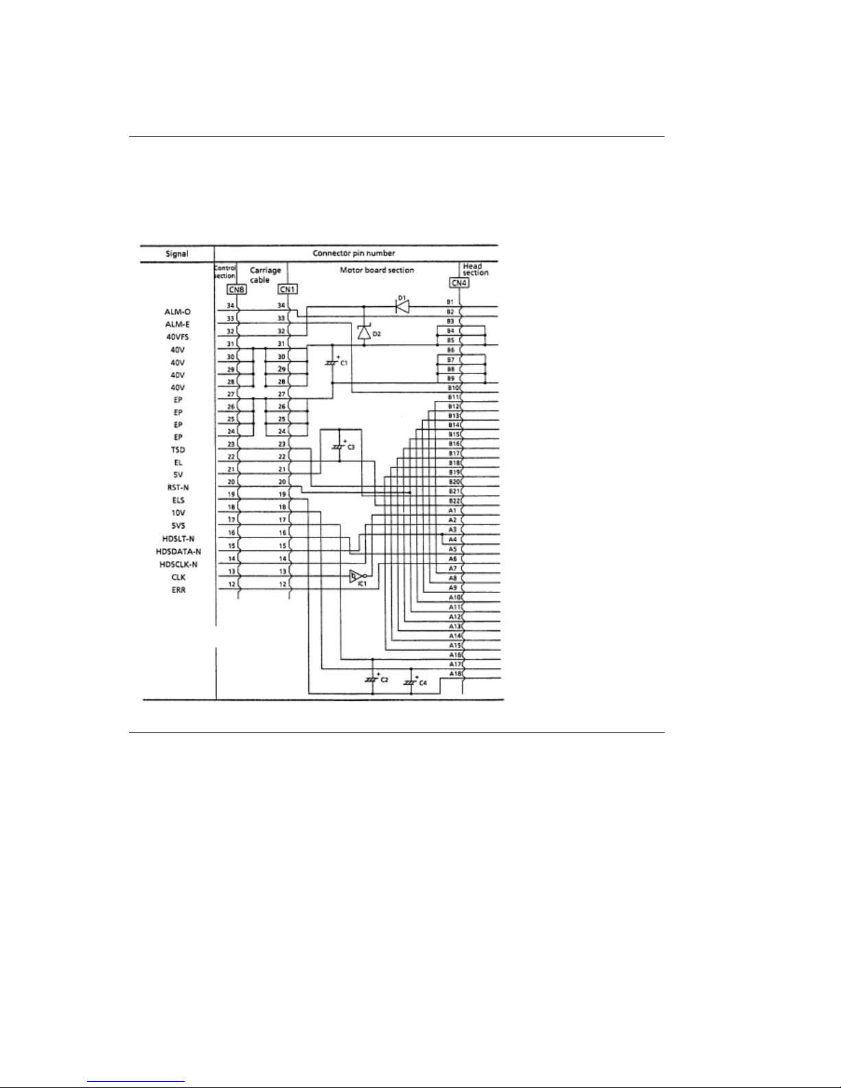
Interconnect Diagram: Control Board to Printhead
Interconnect Diagram: Control Board to Printhead
Note: The printhead coil resistance values ARE NOT LISTED.
The individual print wire control lines CANNOT be accessed on this printhead.
ML590/591 ( 96-02-07 )
Page 67
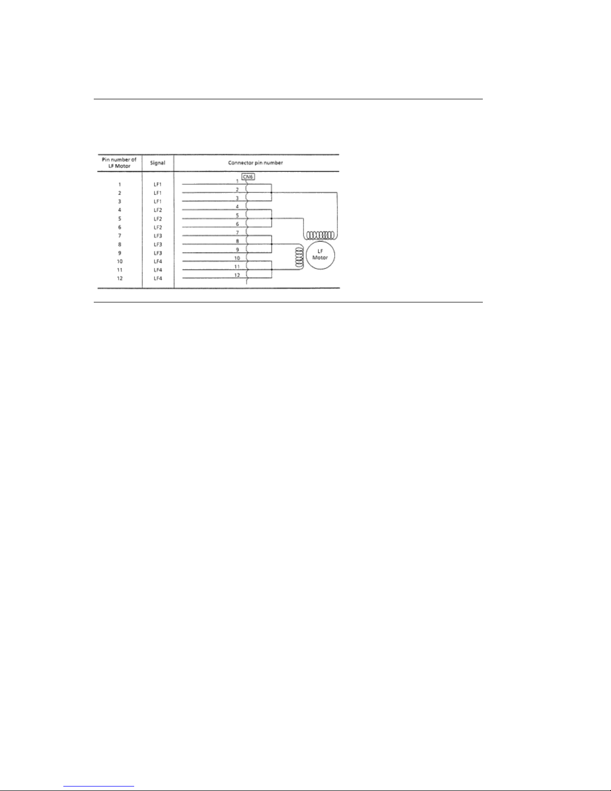
Line Feed Motor Resistance
Line Feed Motor Resistance
The resistance of each coil should be approximately 13 ohms.
ML590/591 ( 96-02-07 )
Page 68

Space Motor Resistance
Space Motor Resistance
The resistance of each coil should be approximately 5 ohms.
ML590/591 ( 96-02-07 )
Page 69

Printhead Operation
Printhead Operation
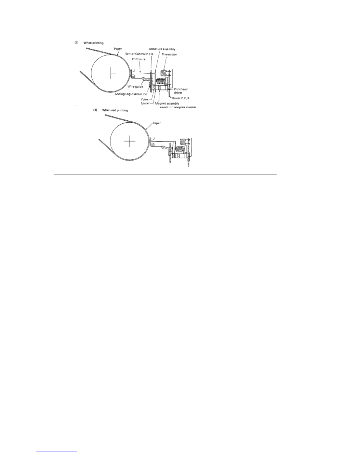
When the printhead is idle, the armature is attracted to the permanent magnet. The print wires,
which are attached to each armature, are then concealed inside the wire guide.
When a signal to print a character is received, current flows through a coil. The magnetic field
generated by the coil opposes the magnetic field between the armature and the permanent
magnet. The armature is then driven in the direction of the platen by the force of the armature
spring. The print wire, which is attached to the armature, protrudes from the tip of the wire guide,
strikes the paper through the ribbon and prints a dot on the paper.
As the armature gets closer to the electrode of the analog sensor, the capacitance between them
increases and a small amount of current flows. This current is amplified and sent to the logic
control LSI to indicate armature activity. In order to attain optimum drive time, this information is
transferred to the MPU. The MPU continually modifies the head gap to maintain the optimum
drive time condition.
The analog sensor element monitors all of the pins. The difference in pin stroke due to the
curvature of the platen is compensated for at the logic control section of the printhead and is not
transferred to the MPU.
After the character has been printed, the permanent magnet attracts the armature and the print
wires are retracted into the wire guide.
Two thermistors are used to monitor the printhead temperature.
A thermistor in the printhead prevents over-heating of the coil during periods of continuous
bi-directional printing. If the printhead temperature exceeds 110 degrees Celsius, the printer will
switch to unidirectional print. If the temperature exceeds 115 degrees Celsius, printing will stop.
Once the printhead cools, printing will resume. When the temperature of the coil exceeds the
pre-determined limits, the control circuit detects the thermistor signal (TSD).
A thermistor in the printhead driver monitors the temperature of the driver. If the temperature of
the driver exceeds the pre-determined limits (110 degrees Celsius - unidirectional printing / 115
degrees Celsius - printing stops) the control circuit detects the thermistor signal (TSD). The
voltage of the TSD signal is monitored at the MPU A/D port to control the pass number and print
method (unidirectional / bi-directional) at each of seven levels.
ML590/591 ( 96-02-07 )
Page 70
ML590/591 ( 96-02-07 )
Page 71
2.2.02 Spacing Mechanism
2.2.02 Spacing Mechanism
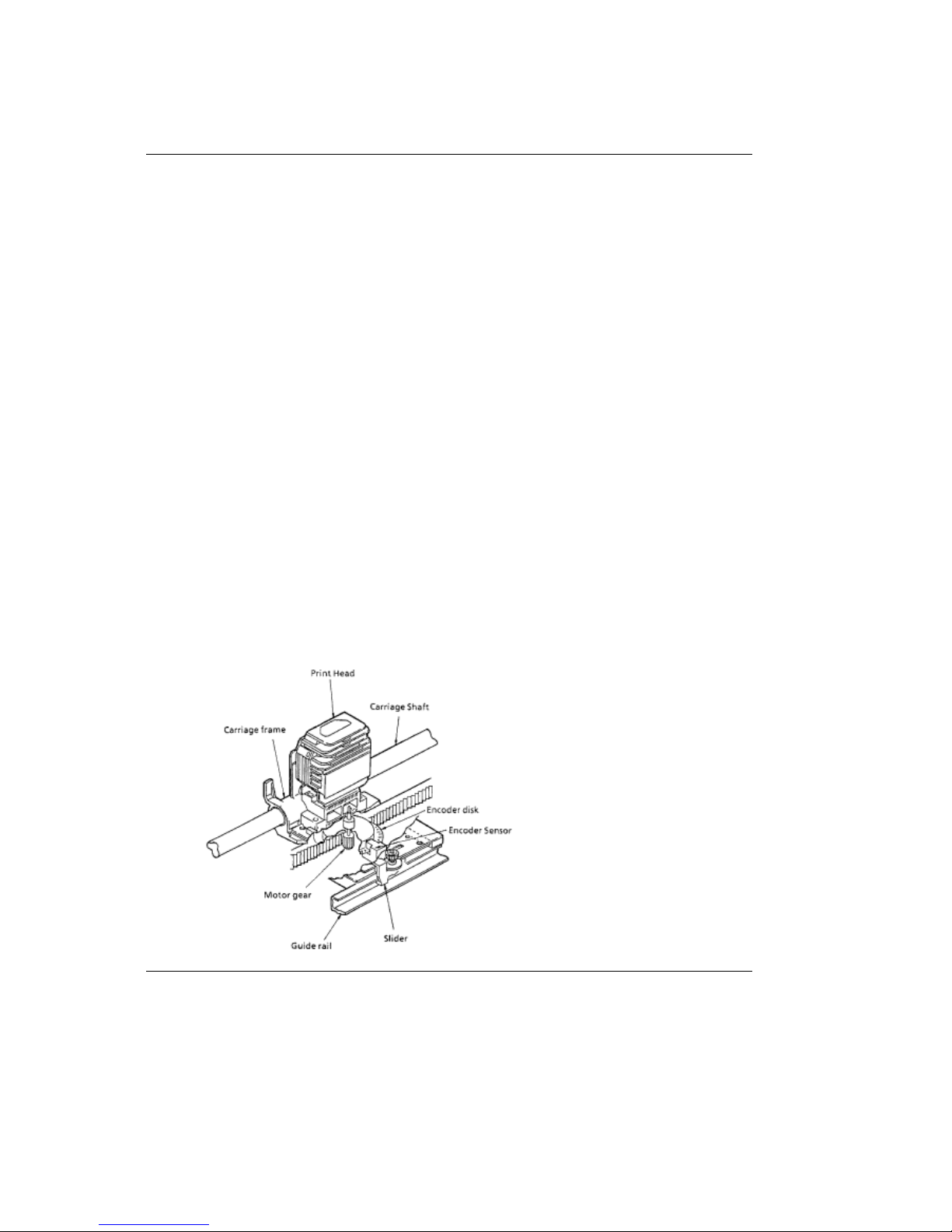
The spacing mechanism consists of a carriage shaft (mounted parallel to the platen), and a
carriage frame which moves along the shaft. The carriage frame is driven by a DC servo motor
mounted on the carriage frame. Items included in the spacing mechanism are listed below.
Space Motor Assembly
DC Servo Motor
Motor gear
Sensor
Encoder Disk
Carriage Frame
Carriage Shaft
Space Rack
Spacing Operation
The carriage frame, which contains the printhead and space motor, moves along the carriage
shaft parallel to the platen. When the space motor rotates, the driving force is transmitted to the
motor gear. As the motor gear rotates, the carriage moves along the platen. For every revolution
of the DC servo motor, the carriage frame moves 0.8 inch (20.32 mm).
As the DC servo motor rotates, a slotted disk (called the encoder disk), passes between a light
source and two photosensors. The position of the carriage frame can be determined by counting
the pulses generated by the photosensors.
In the same way, the rotation of the space motor can be recognized and controlled by measuring
the phase relationship and the pulse width of the signals generated by the photosensors.
ML590/591 ( 96-02-07 )
Page 72
2.2.03 Head Gap Mechanism
2.2.03 Head Gap Mechanism
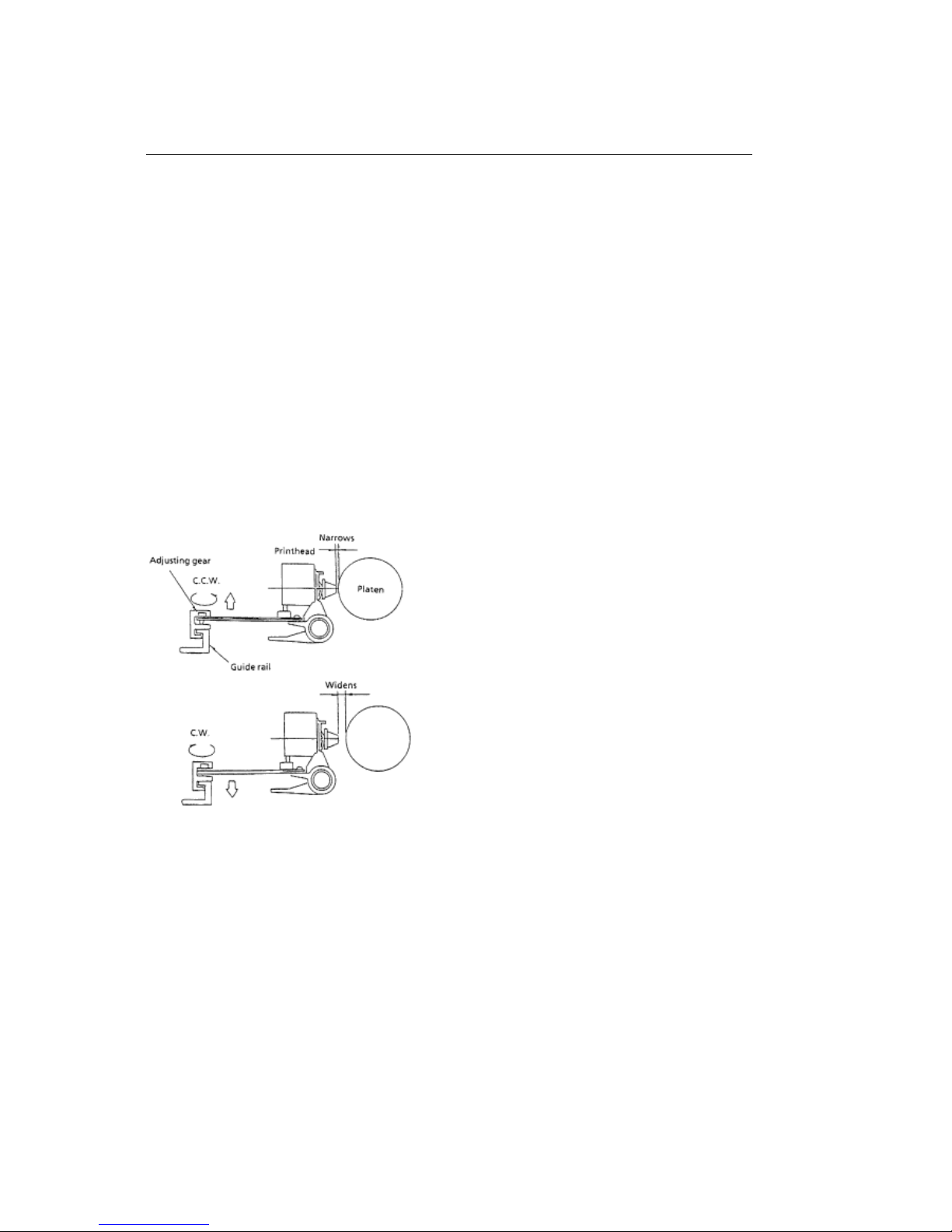
The head gap is automatically set for the thickness of the medium loaded in the printer. In the
case of envelopes, where the medium thickness varies as the printhead moves along the platen,
the head gap changes to compensate for the differences in thickness.
Head Gap Setting Operation
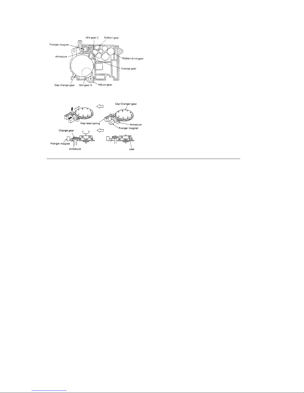
Once printing starts, the space motor rotates the ribbon gear, causing idle gear C to turn the
change gear.
When the MPU requests a change in the head gap setting, the GAP-P signal causes the
armature (which is holding the change gear) to be attracted to the pranger magnet. The gap reset
spring can now push the change gear so it contacts the gap change gear.
The rotation of the gap change gear causes idle gear D to turn the adjust gear. The adjust gear
turns the adjusting screw, resulting in a new head gap setting.
Note: As the adjusting screw turns counter-clockwise, the gap narrows.
As the adjusting screw turns clockwise, the gap widens.
There is a cam at each setting of the gap change gear. When the change gear is at the top of
the cam, the change gear disengages from the gap change gear. At this time, the armature
resets, changing the head gap by one setting.
The head gap is modified in .06 mm units for each range setting.
ML590/591 ( 96-02-07 )
Page 73
ML590/591 ( 96-02-07 )
Page 74
2.2.04 Ribbon Drive Mechanism
2.2.04 Ribbon Drive Mechanism
Black Ribbon Drive Operation
The ribbon drive mechanism feeds the ribbon in synchronization with the spacing operation. The
force required to drive the ribbon is obtained from the space motor.
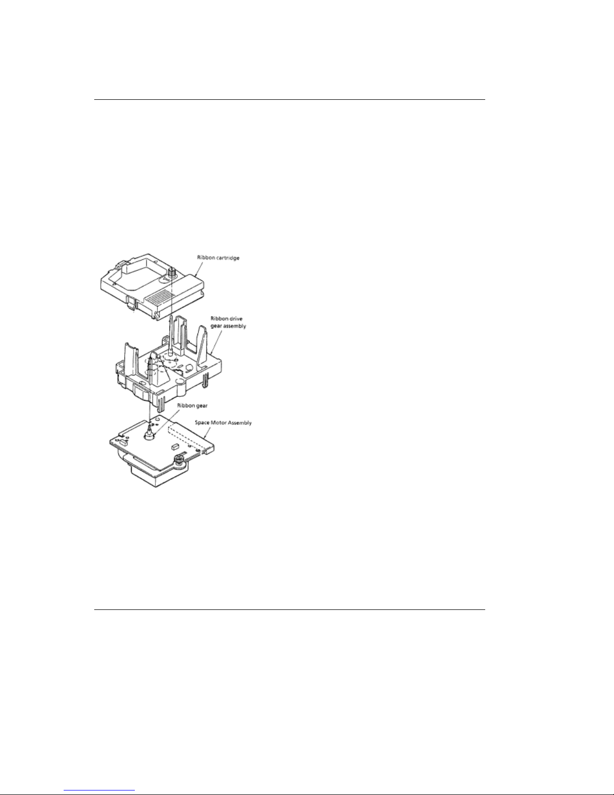
The ribbon drive mechanism is composed of the following items.
Ribbon drive gear assembly
Ribbon gear (located on the space motor assembly)
Ribbon cartridge
A continuous loop ribbon with uni-directional feed is used. Ink is supplied from an ink tank, which
is built into the ribbon cartridge.
When the space motor turns, the ribbon gear on the spacing motor shaft rotates. The rotation is
transmitted via a combination of gears, from the ribbon drive gear assembly to the drive gear in
the ribbon cartridge.
Although the space motor moves in both the forward and reverse directions during bi-directional
printing, the gears in the ribbon drive assembly maintain uni-directional ribbon feed by switching
the rotation direction of the gears.
ML590/591 ( 96-02-07 )
Page 75
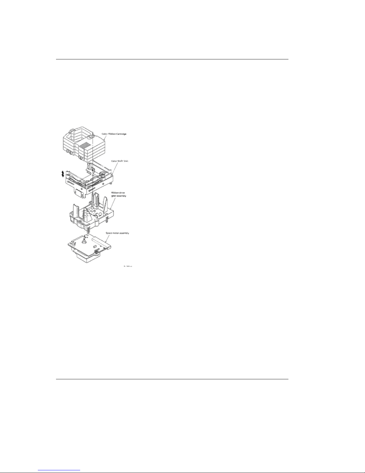
Color Ribbon Shift Mechanism
Color Ribbon Shift Mechanism
Items of the color ribbon unit option are listed below.
Color shift unit
Color ribbon (4 colors)
Four colors can be selected by sliding the color ribbon holder up or down. Here is a description of
how the ribbon holder is shifted.
As the space motor moves, idle gear C on the ribbon drive unit rotates. Idle gear C rotates the
color idle gear, located in the color shift unit.
When the color-P signal from the main control board activates the pranger magnet, the magnet
attracts the armature. This causes the reset spring to force the change gear downward. The color
idle gear rotates the change gear, which turns the color change gear. The color change gear
turns the color cam shaft. The rotation of the color cam shaft moves the color ribbon holder
up/down to select the desired ribbon color.
There is a cam at each setting of the color change gear. When the change gear is at the top of
the cam, the change gear disengages from the color change gear. At this time, the armature
resets, changing the color band selection by one setting.
#####
ML590/591 ( 96-02-07 )
Page 76
2.2.05 Line Feed Mechanism
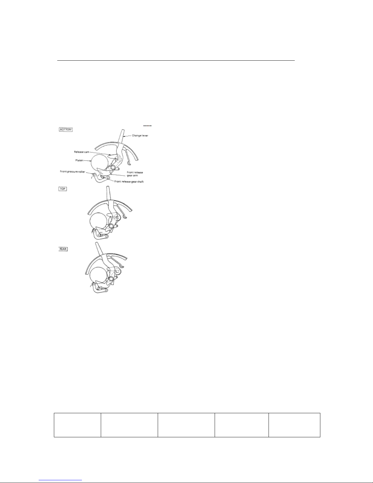
2.2.05 Line Feed Mechanism
The line feed operation is accomplished by activating the line feed motor which turns the platen.
The rotation of the platen is used to feed paper from the selected paper path.
Components of the paper feed mechanism are listed below.
Line Feed Motor (pulse motor) with Gears
Line Feed Idler Gear
Platen
Rear Tractor Feed Unit
Pressure Roller
Change Lever (Paper Path Selection Lever)
The change lever is used to select one of three different paper paths; top, rear or bottom.
Paper Clamp Mechanism
Moving the Change Lever between the Bottom, Top and Rear positions, changes the positions of
the Front Release Gear Arm and the Release Cam.
The movement of the Front Release Gear Arm changes the position of the Front Release Gear
Shaft. This causes the Front Pressure Roller to open or close.
The movement of the Release Cam causes the Rear Pressure Roller to open or close.
Position of
Change Lever
Status of Front
Pressure Roller
Tension of Front
Pressure Roller
Status of Rear
Pressure Roller
Tension of Rear
Pressure Roller
ML590/591 ( 96-02-07 )
Page 77

Bottom OPEN N/A OPEN N/A
Top CLOSED 250 g CLOSED 700 g
Rear CLOSED 90 g OPEN N/A
ML590/591 ( 96-02-07 )
Page 78
Cut Sheet/Continuous Sheet Switching Mechanism
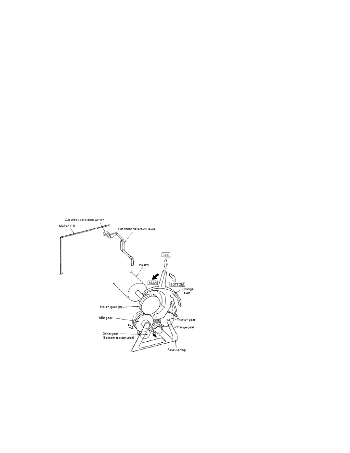
Cut Sheet/Continuous Sheet Switching Mechanism
Top Feed (for cut sheet paper)
When cut sheet paper is used, place the change lever in the Top Feed position.
As the platen turns, the platen gear causes the idle gear to rotate.
At this time, the rear and front pressure rollers press against the platen and feed the cut sheet.
The cut sheet detection lever enables the cut sheet detection switch, which is located on the
main control board. This places the printer in the cut sheet mode.
When cut sheet paper is placed between the platen and the paper chute, the printer automatically
feeds the sheet to the print start position.
Rear/Bottom Feed (for continuous feed paper)
When the continuous feed paper is used, either with the rear tractor, optional bottom tractor or
optional pull tractor, place the change lever in the Rear/Bottom Feed position.
When the change lever is placed in this position, the reset spring pushes the change gear. In this
position, the idle gear is engaged with the bottom tractor unit drive gear and the tractor gear. As
the platen turns, power is transferred from the platen gear - to the idle gear - to the change gear and to the push tractor shaft.
ML590/591 ( 96-02-07 )
Page 79
Cut Sheet Paper Feed Operation
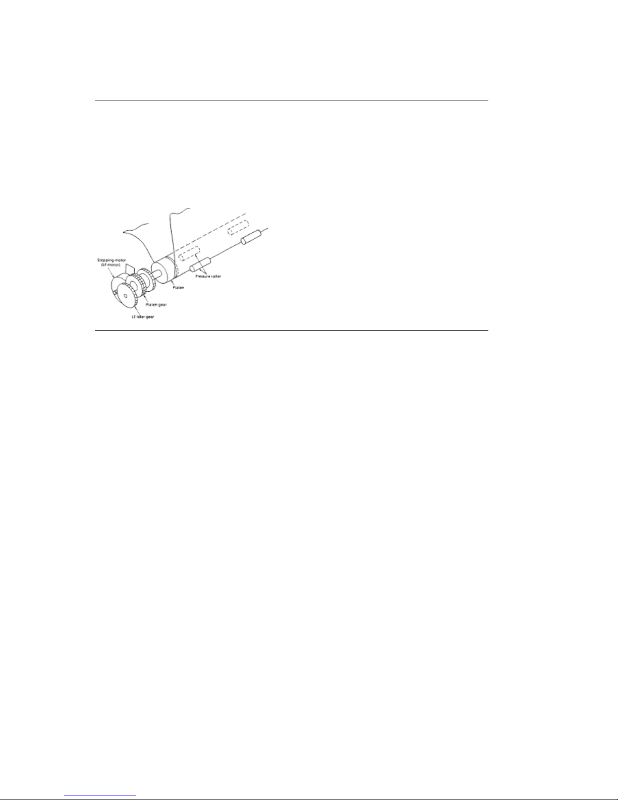
Cut Sheet Paper Feed Operation
As the line feed motor rotates, power is transferred through decelerating gears (line feed idler
gear, platen gear) to the platen.
When using cut sheet paper, the change lever must be in the TOP position so the platen and
pressure rollers can feed the paper. This also disengages the push tractor.
ML590/591 ( 96-02-07 )
Page 80
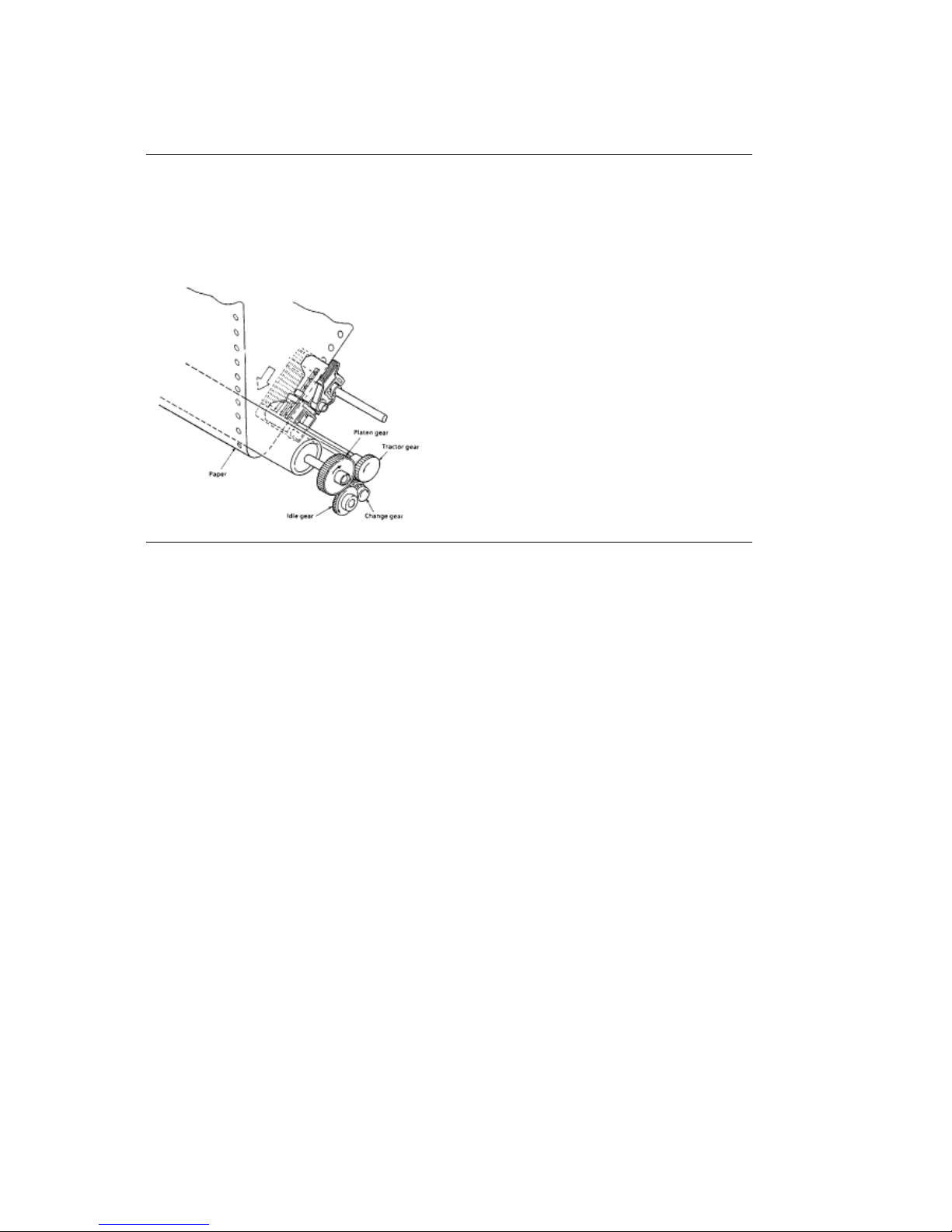
Continuous Paper Feed (Rear Tractor Mechanism)
Continuous Paper Feed (Rear Tractor Mechanism)
As the platen rotates, power is transferred to the tractor gear from the platen gear, the idler gear
and the change gear. The tractor gear drives the pin tractor belts which feed the continuous
paper.
ML590/591 ( 96-02-07 )
Page 81
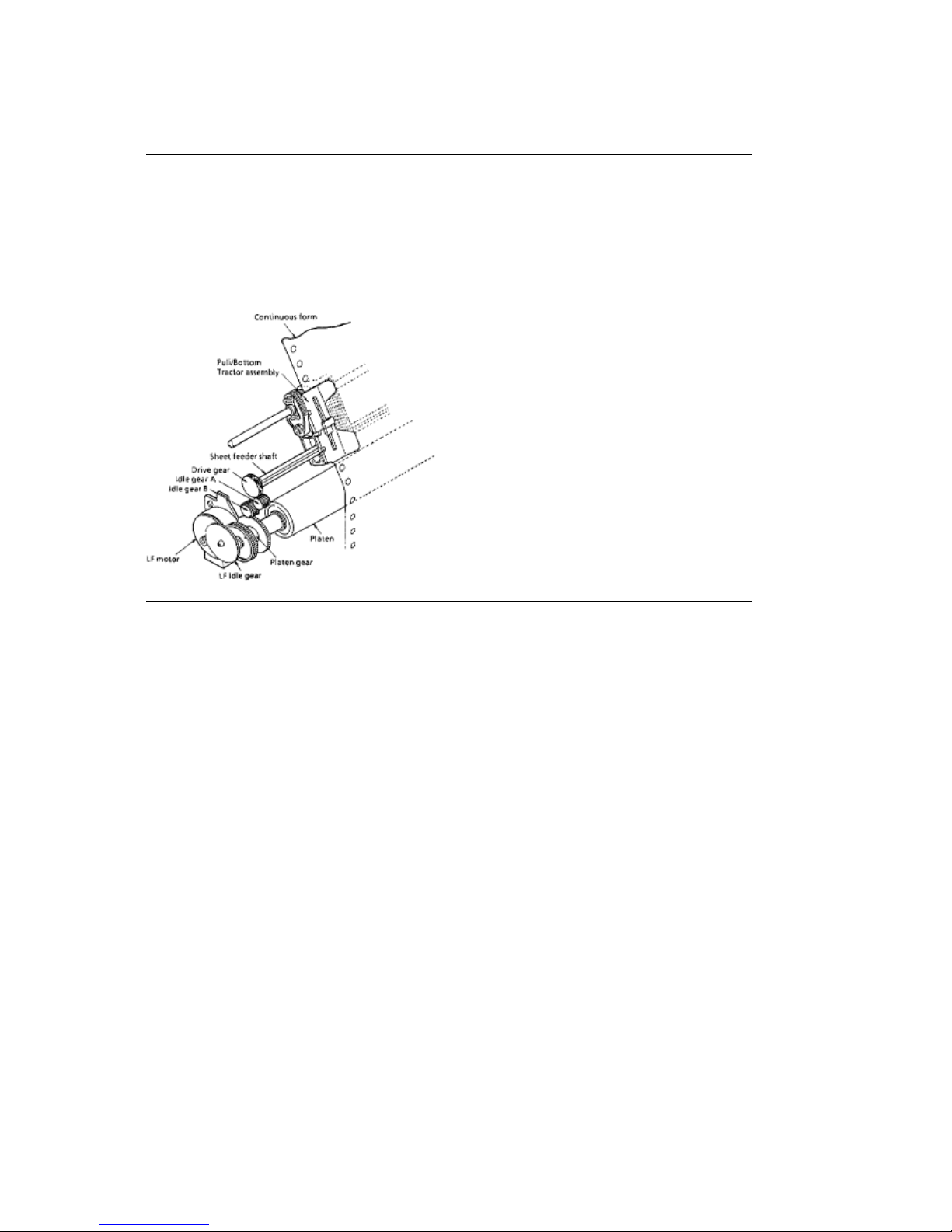
Continuous Paper Feed (Pull Tractor Mechanism)
Continuous Paper Feed (Pull Tractor Mechanism)
Bottom feed of continuous sheets is possible only when an optional pull tractor unit is installed.
As the platen rotates, power is transferred to the drive gear from the LF idler gear, the platen
gear, idler gear B and idler gear A. The drive gear turns the pull tractor assembly which feed the
continuous paper.
ML590/591 ( 96-02-07 )
Page 82
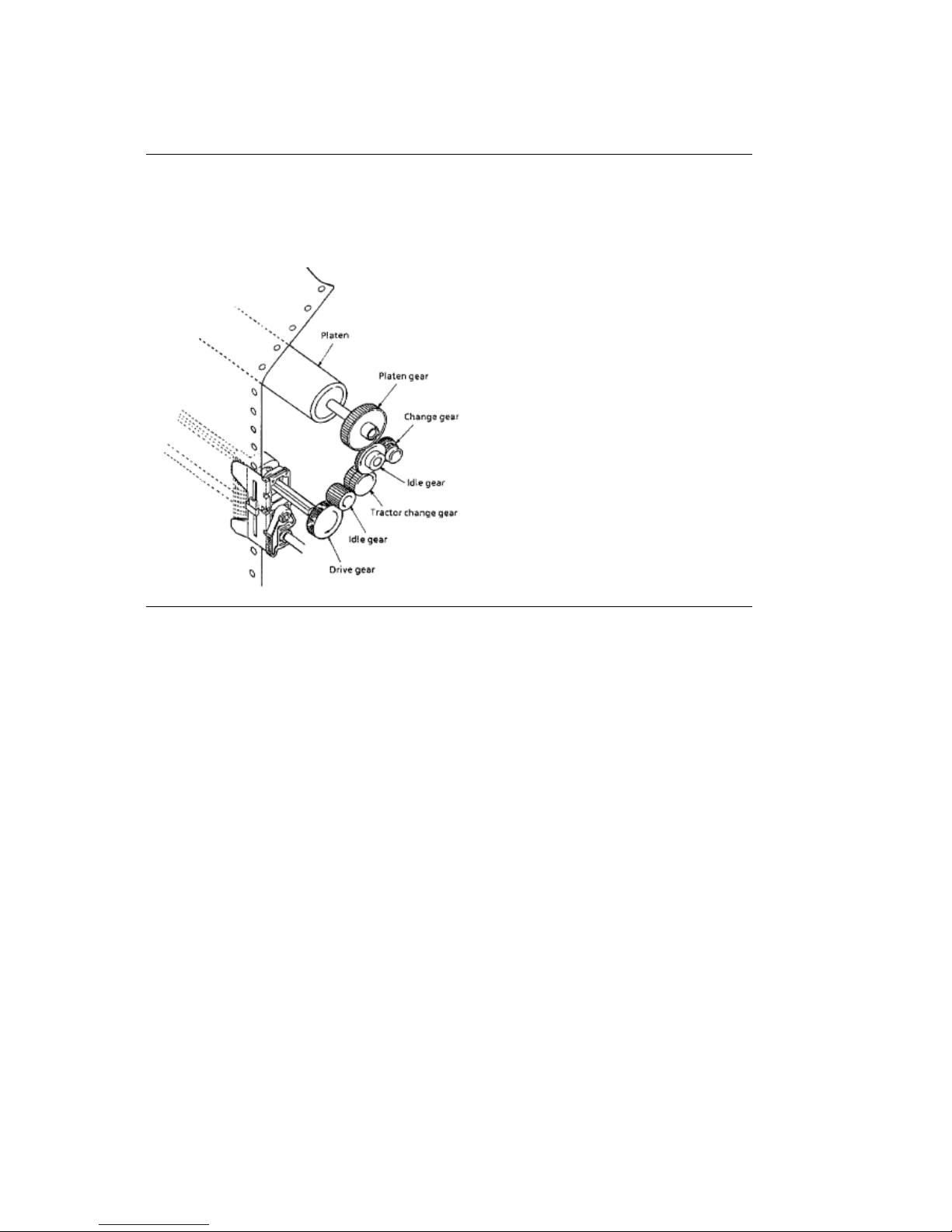
Continuous Paper Feed (Bottom Tractor Feed Mechanism)
Continuous Paper Feed (Bottom Tractor Feed Mechanism)
As the platen rotates, power is transferred to the drive gear from the platen gear, the idle gear
and the tractor change gear. The drive gear turns the pin tractor belts on the bottom tractor feed
unit to feed the continuous paper.
ML590/591 ( 96-02-07 )
Page 83
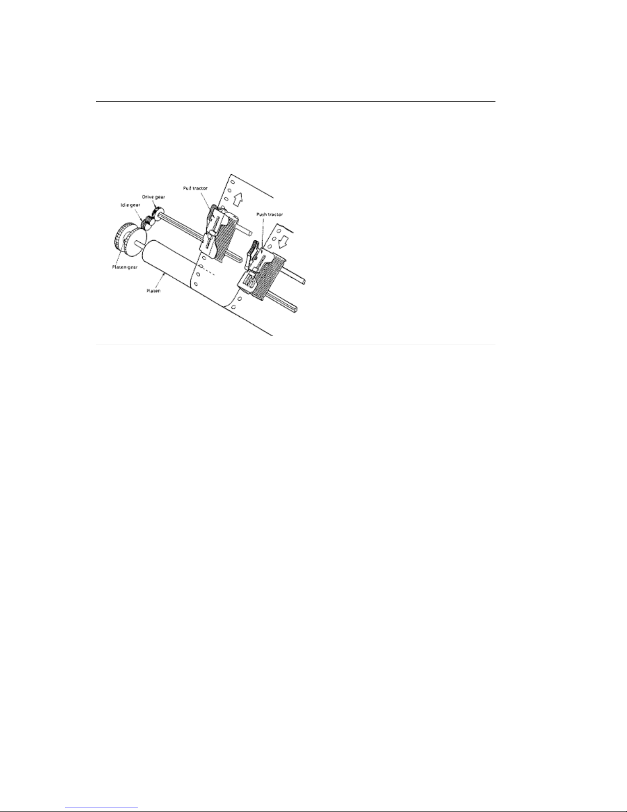
Continuous Paper Feed (Push/Pull Tractor Mechanism)
Continuous Paper Feed (Push/Pull Tractor Mechanism)
This mechanism consists of an optional pull tractor and a standard push tractor mechanism.
Continuous paper is fed by these two tractors at the same time.
ML590/591 ( 96-02-07 )
Page 84
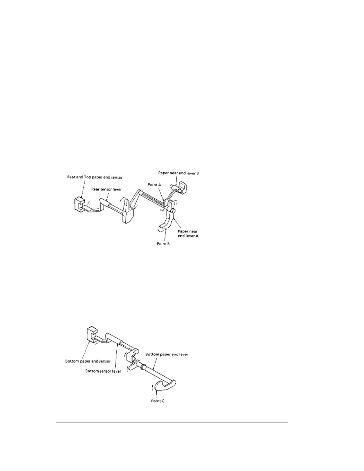
2.2.06 Paper Detection Mechanism
2.2.06 Paper Detection Mechanism
Top Feed Paper Detection
When the cut sheet paper is inserted into the printer, Point A of Paper Near EndLever - B is
pushed backward rotating Paper Near End Lever - A.
As Paper Near End Lever - A rotates, it contacts the Rear Sensor Lever, rotating it.
The Rear Sensor Lever rotates, unblocking the Rear / Top Paper End Sensor.
Rear Feed Detection
When paper is fed from the rear push tractor, Point B is pushed backward rotating Paper Near
End Lever - A.
As Paper Near End Lever - A rotates, it contacts the Rear Sensor Lever, rotating it.
The Rear Sensor Lever rotates, unblocking the Rear / Top Paper End Sensor.
Bottom Feed Detection
When the paper is fed from the bottom of the printer, Point C is pushed, rotating the Bottom
Paper End Lever.
As the Bottom Paper End Lever rotates, it contacts and rotates the Bottom Sensor Lever.
The Bottom Sensor Lever rotates, unblocking the Bottom Paper End Sensor.
Note: The method for detecting a paper-end condition is in the reverse order,
that is, paper-end is detected when the Paper End Sensor is blocked.
ML590/591 ( 96-02-07 )
Page 85
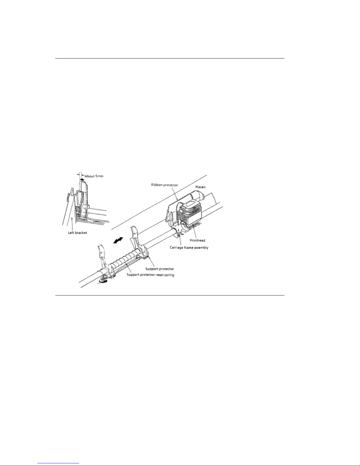
2.2.07 Support Protector Mechanism
2.2.07 Support Protector Mechanism
During printer initialization, the support protector is latched in the stored position (approximately 5
mm from the left bracket of the main frame).
Just before paper is loaded, the printhead moves towards the left bracket and unlatches the
support protector.
As the printhead moves to the right, the support protector reset spring pushes the support
protector toward the center of the platen. With the support protector in this position, the ribbon
protector and the support protector prevent the leading edge of the paper from curling or folding.
Once the paper is ejected, the printhead slowly moves towards the left bracket. The support
protector is latched in the stored position when it is pushed to approximately 5 mm from the left
bracket.
ML590/591 ( 96-02-07 )
Page 86
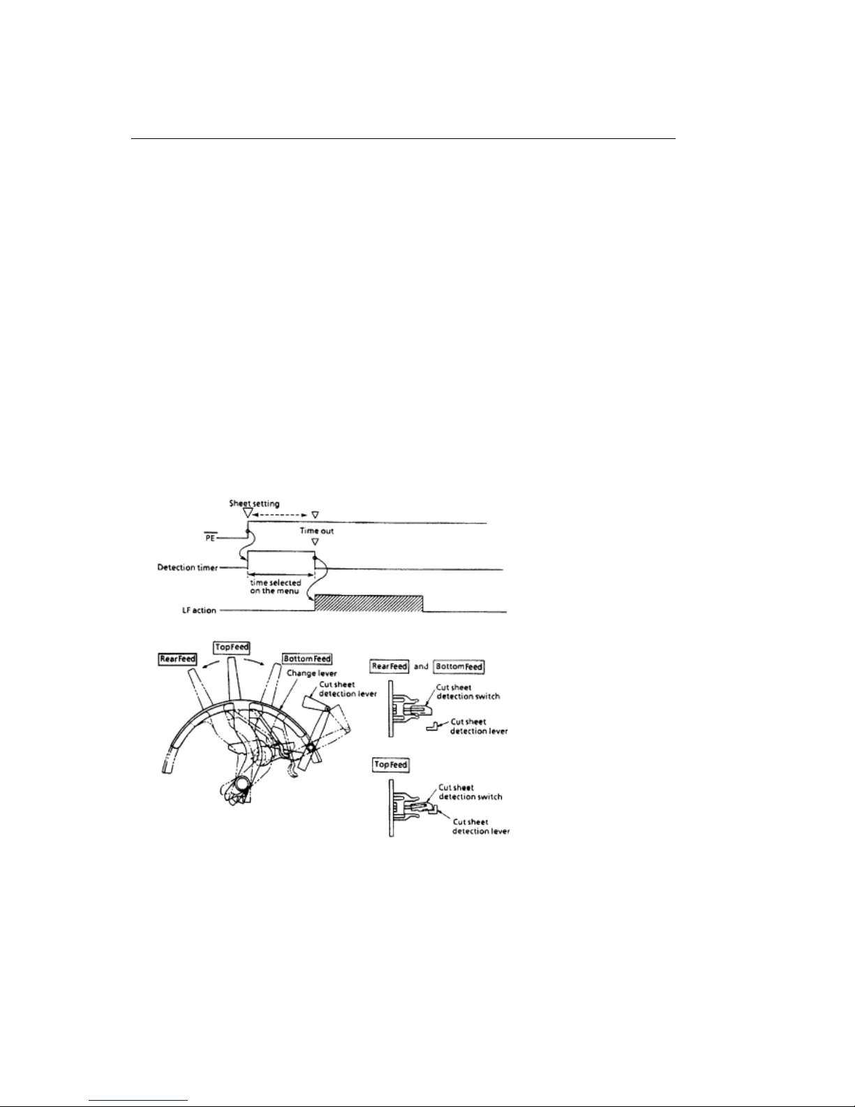
2.2.08 Automatic Paper Load
2.2.08 Automatic Paper Load
The Microline 590/591 printers will automatically detect cut sheet paper and feed the paper to the
TOP OF FORM position.
Cut Sheet Paper
Set the change lever to the TOP FEED position.
Note: When the change lever is in the TOP FEED position, the cut sheet detection lever
contacts the cut sheet detection switch (BASW) which is located on the main control
board.
Insert the sheet of paper between the platen and the paper chute.
Once paper is detected at the paper end sensor and the amount of time selected on the Wait
Time setting of the menu has lapsed, the line feed motor will feed the paper until the leading
edge of the paper reaches the top of form position.
Continuous Feed Paper
Set the change lever to either the REAR FEED or BOTTOM FEED position.
NOTE:
When the change lever is in the REAR FEED or BOTTOM FEED position, the cut sheet
detection lever does not contact the cut sheet detection switch (BASW) which is located on the
ML590/591 ( 96-02-07 )
Page 87
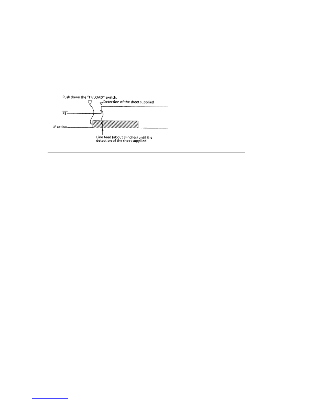
main control board.
Place continuous feed paper in the appropriate tractor.
Press the "FF/LOAD" switch.
The line feed motor will feed the paper until the leading edge of the paper to the top of form
position.
ML590/591 ( 96-02-07 )
Page 88
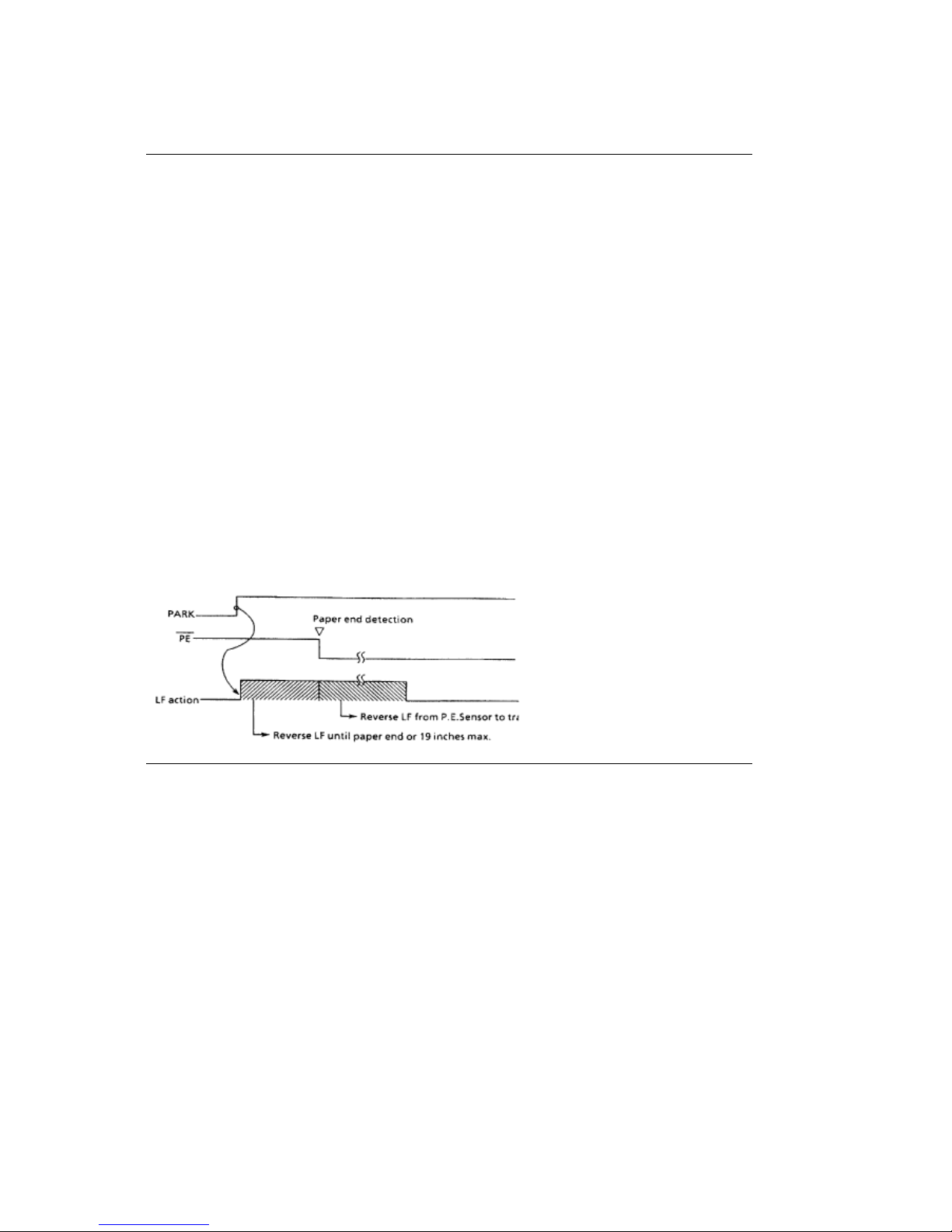
2.2.09 Paper Park
2.2.09 Paper Park
If continuous feed paper is installed and printing on cut sheet paper is desired, it is not necessary
to unload the continuous feed paper. The Paper Park feature provides a means of retracting the
continuous feed paper from the paper path, to allow feeding of the cut sheet paper.
Paper Park Operation
Make sure the change lever is in the REAR FEED or BOTTOM FEED position.
Press the "PARK" switch on the operation panel.
A reverse line feed operation retracts the paper until paper-end occurs or 19 inches of paper
have been retracted.
Note: Retracting 19 inches of paper without detecting a paper-end condition causes the line
feed operation to stop. The line feed operation stops because the printer assumes a jam
has occurred.
The operator can press the SEL switch to reset the ALARM LED and press the PARK switch to
continue the park operation.
This operation may be useful when length of the paper to be parked is greater than 19 inches.
ML590/591 ( 96-02-07 )
Page 89

Chapter 3
3.1.01 General Information
3.1.01 General Information
This section lists the parts replacement, adjustment, cleaning, lubrication, and shipping
procedures.
Disassembly should not be performed unless absolutely necessary.
NEVER
perform disassembly
on a malfunctioning printer until you have followed the failure analysis procedures in Section Four
of this Service Handbook.(
)
Follow the procedures listed in Adjustments and Service Settings.{
} Adjustments may be
required when either consumable or parts are replaced. Failure to perform these procedures
could result in unnecessary service calls.
Proper performance of maintenance and cleaning will help to achieve the best possible print
quality from the printer.
ML590/591 ( 96-02-07 )
Page 90

3.1.02 Maintenance Tools
3.1.02 Maintenance Tools
The following tools are required to service the printer.
#2 Phillips Screwdriver (with magnetic tip)
Straight-slot Screwdriver
Needle Nose Pliers (4 Inch)
Wire Cutters
Digital Multimeter
Feeler Gauge (capable of measuring .014 inches)
Shop Vacuum
Clean, soft, and lint-free Cloth
All-Purpose Cleaner
Contact Kleen
(Okidata P/N 51802301)
Platen Cleaner
Machine Grease
Machine Oil
ML590/591 ( 96-02-07 )
Page 91

3.1.03 Maintenance Precautions
3.1.03 Maintenance Precautions
1. Do not disassemble the unit if it is operating normally.
2. Before starting disassembly and assembly, always turn the AC power switch OFF and pull out
the AC plug.
3. Detach the interface cable, if installed.
4. Do not remove parts unnecessarily. Try to keep disassembly to a minimum.
5. Use the recommended maintenance tools.
6. When disassembling, follow the listed sequence. Failure to follow the correct sequence may
result in damaged parts.
7. Since screws, collars and other small parts are easily lost, they should be temporarily attached to
the original positions.
8. When handling circuit boards use extreme care. Integrated circuits (microprocessors, ROM, and
RAM) can be destroyed by static electricity.
9. Do not place printed circuit boards directly on conductive surfaces.
10 Follow the recommended procedures when replacing assemblies and units.
11 Perform the printhead gap adjustment procedure (Refer to Section 3.3 of this Service
Handbook(
)) when the any of the following occur.
Print Quality is darker on one side of the document.
Parts are replaced:
1. Printhead(3.2.02)
2. Space Motor Assembly(3.2.11)
3. Space Rack(3.2.13)
4. Guide Rail(3.2.15)
5. Platen Assembly(3.2.19)
6. Carriage Shaft(3.2.25)
ML590/591 ( 96-02-07 )
Page 92

3.2 Disassembly/Assembly Procedures
3.2 DISASSEMBLY/ASSEMBLY PROCEDURES
General Information
This section contains the printer disassembly procedures. Only the removal procedures are
explained here. Reverse the procedure for the installation.
At the bottom of each procedure is a listing of the parts covered in that procedure. The Okidata
part number, item description, comment (RSPL, Option, Consumable) and cross-reference to
Appendix B is provided for each part. Items included in the Recommended Spare Parts List are
indicated by the acronym RSPL. N/A will appear where a part number is not available.
590 indicates that the item is specific to the Microline 590.
591 indicates that the item is specific to the Microline 591.
Both indicates that the item is common to both printers.
Part Description Item Comment Appendix B
Number Reference
This Service Handbook lists the disassembly procedures for major components of the unit.
Okidata
DOES NOT
recommend disassembling a unit which is operating normally. If you decide
to perform disassembly during this training, Okidata recommends that you perform only the
disassembly procedures for RSPL items. All other procedures are provided to assist you in
identifying parts. It is not likely that you will perform these procedures while servicing the unit.
Be sure to read all notes, cautions, and warnings, as they contain important information
regarding disassembly / assembly.
ML590/591 ( 96-02-07 )
Page 93
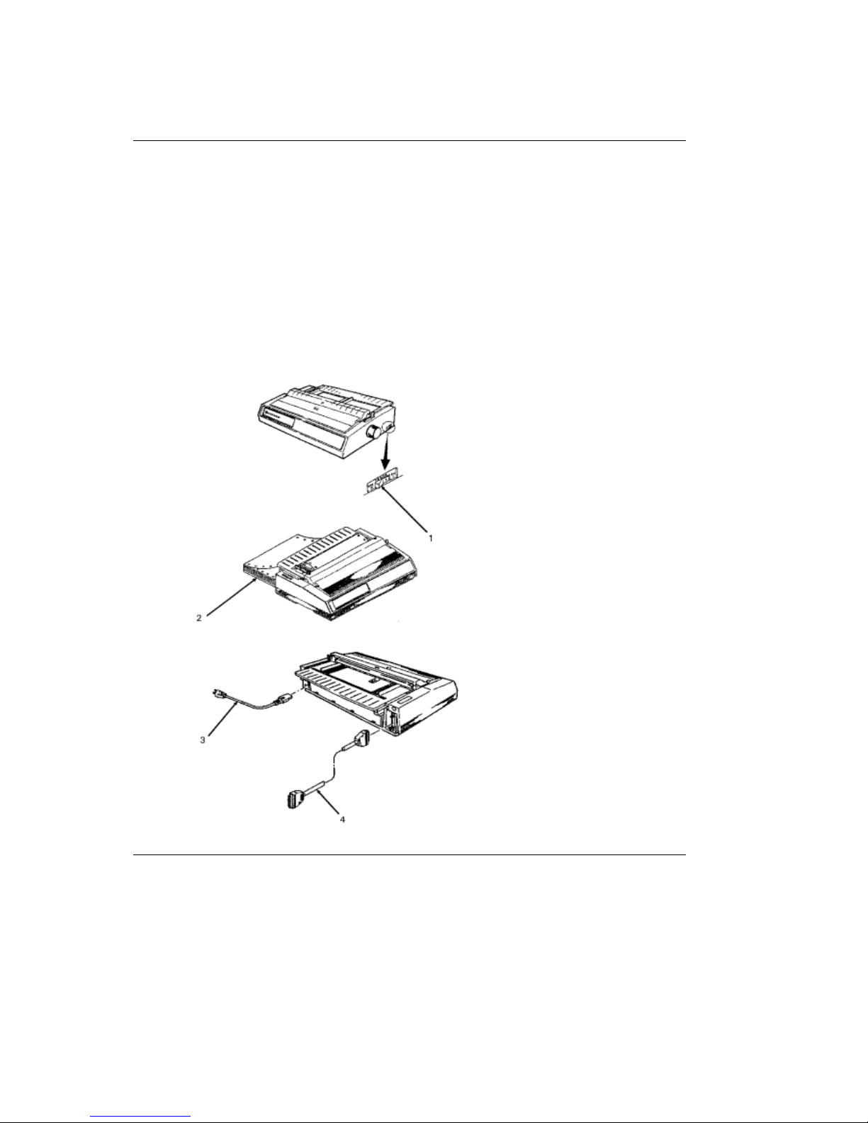
3.2.01 Preliminary Items
3.2.01 Preliminary Items
1. Press the AC switch (1) and power off the printer.
2. Remove the paper, if installed (2).
3. Detach the AC power cord (3).
4. Detach the interface cable, if installed (4).
P/N 56609701 Cord: AC RSPL Both B.2.02
P/N 56624101 Cord: AC 220V (ML Series) Right Angle Option RSPL Both B.2.02
P/N 56624401 Cord: AC 240V Option RSPL Both B.2.07
P/N 70000803 Kit: Parallel Interface Option Both B.2.07
Plug'n'Play Accessory
P/N 70012801 Kit: RS232-C Serial Interface Option Both B.2.07
ML590/591 ( 96-02-07 )
Page 94
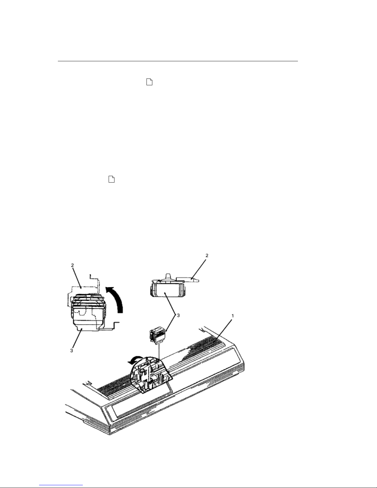
3.2.02 Printhead Assembly
3.2.02 Printhead Assembly
1. Perform this procedure: 3.2.01(
).
2. Open the access cover (1).
3. Lift and remove the ribbon. (Not shown)
4. Pull the head clamp (2) towards the right and then rotate it up to release the printhead (3).
5. Pull the printhead straight up to remove it.
NOTE:
Installation
After installing the printhead, check the printhead gap adjustment. Refer to Section 3.3 of this
Service Handbook.{
}
P/N 52106001 Ribbon: Black Consumable Both B.2.09
P/N 52106002 Ribbon: Color Consumable Both B.2.09
P/N 50707401 Clamp: Head RSPL Both B.2.06
P/N 50217201 Assembly: Printhead RSPL Both B.2.02
ML590/591 ( 96-02-07 )
Page 95
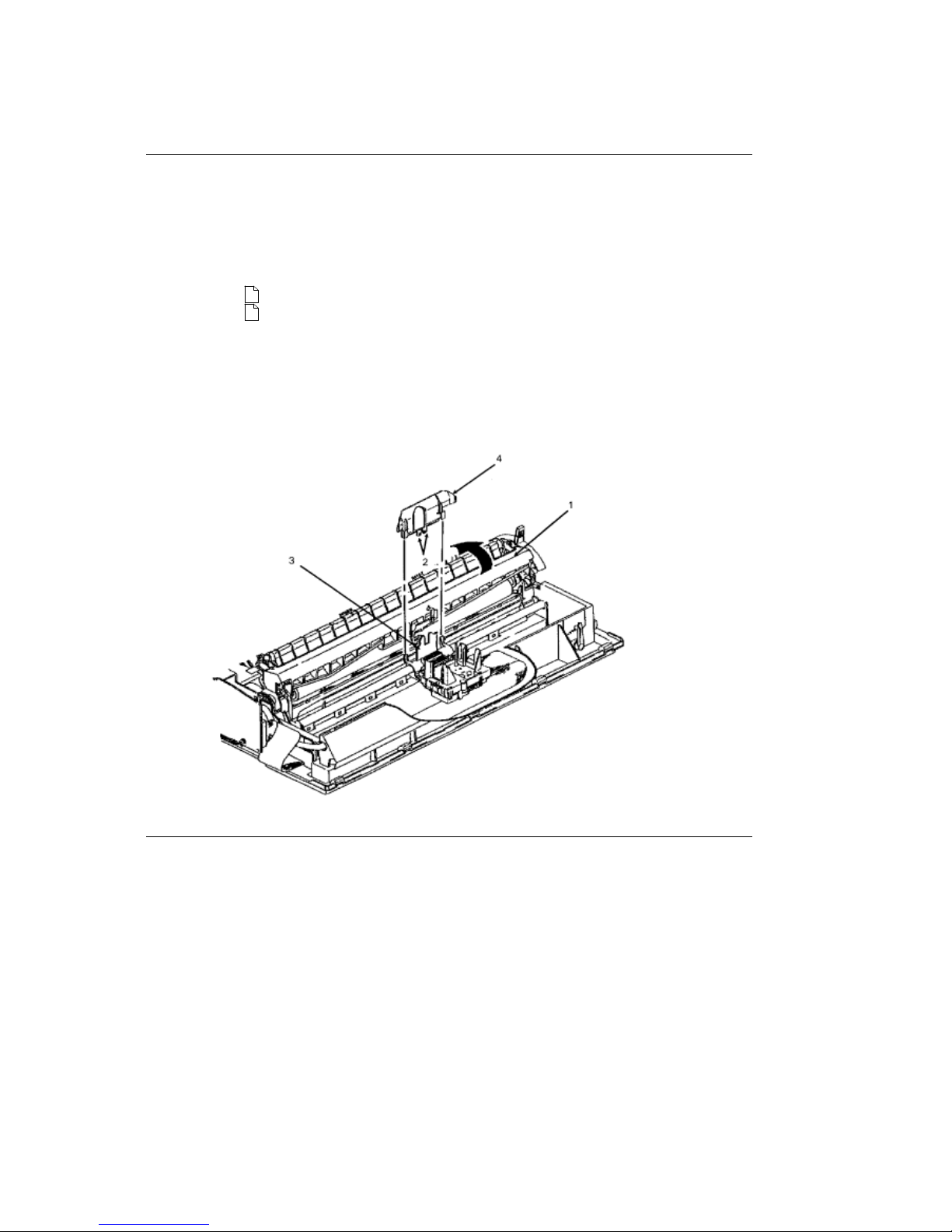
3.2.03 Ribbon Protector
3.2.03 Ribbon Protector
CAUTION
You MUST use a straight slot screwdriver to release the ribbon protector. If you attempt
to lift the protector without releasing the tabs, the protector will break.
1. Perform these procedures:
3.2.01{
}
3.2.02{
}
2. Open the pull-up roller cover (1).
3. Use a straight-slot screwdriver to release the extensions (2) from the carriage frame set (3).
4. Lift the ribbon protector (4) straight up and remove it.
P/N 53562801 Protector: Ribbon RSPL Both B.2.06
ML590/591 ( 96-02-07 )
Page 96
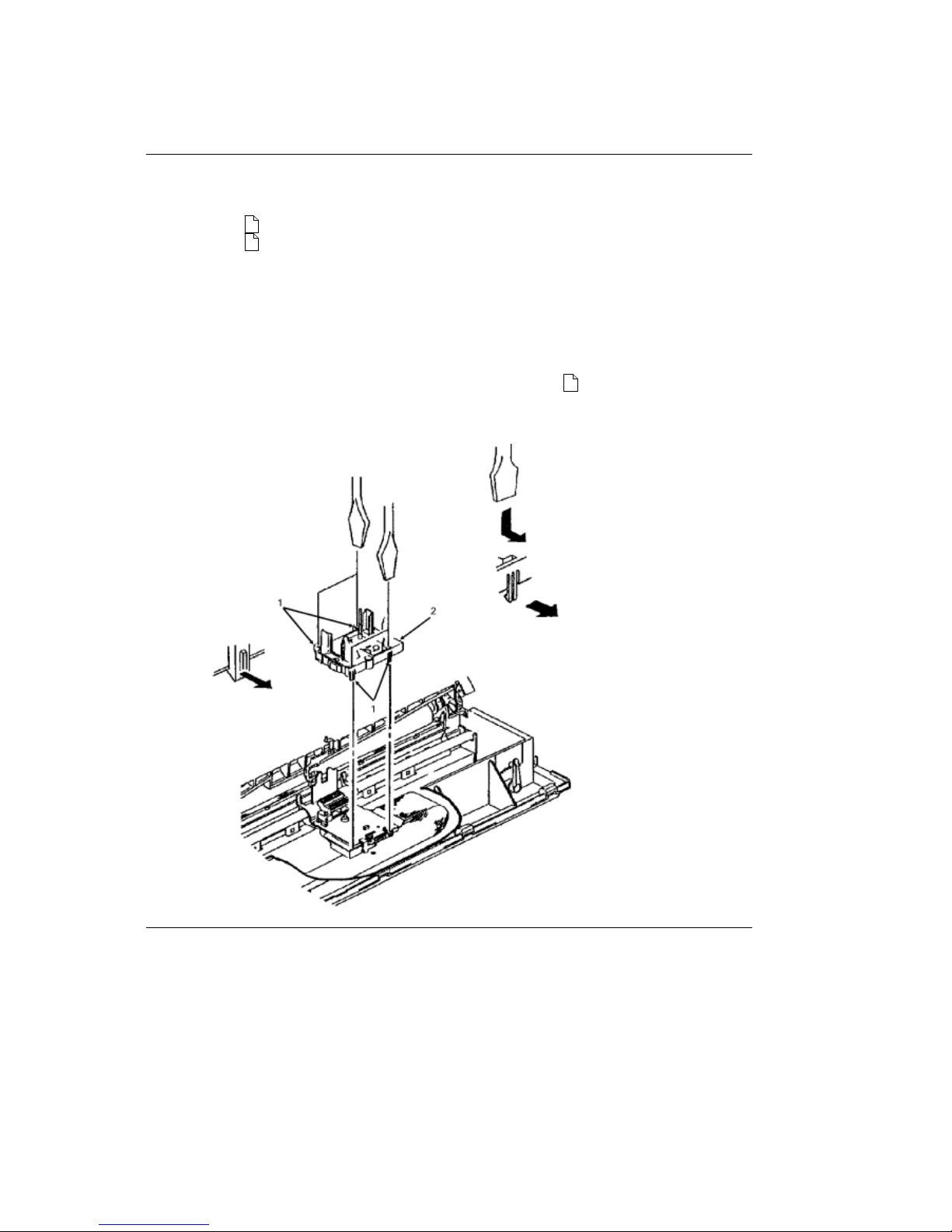
3.2.04 Gear Case Assembly
3.2.04 Gear Case Assembly
1. Perform these procedures:
3.2.01{
}
3.2.02{
}
2. Use a straight-slot screwdriver to release the four claws (1) of the gear case assembly (2).
3. Lift and remove the gear case assembly.
NOTE:
Lubrication
When lubricating, refer to Section 3.5 of this Service Handbook.{
}
P/N 51228501 Gear: Case (Assembly) RSPL Both B.2.06
ML590/591 ( 96-02-07 )
Page 97
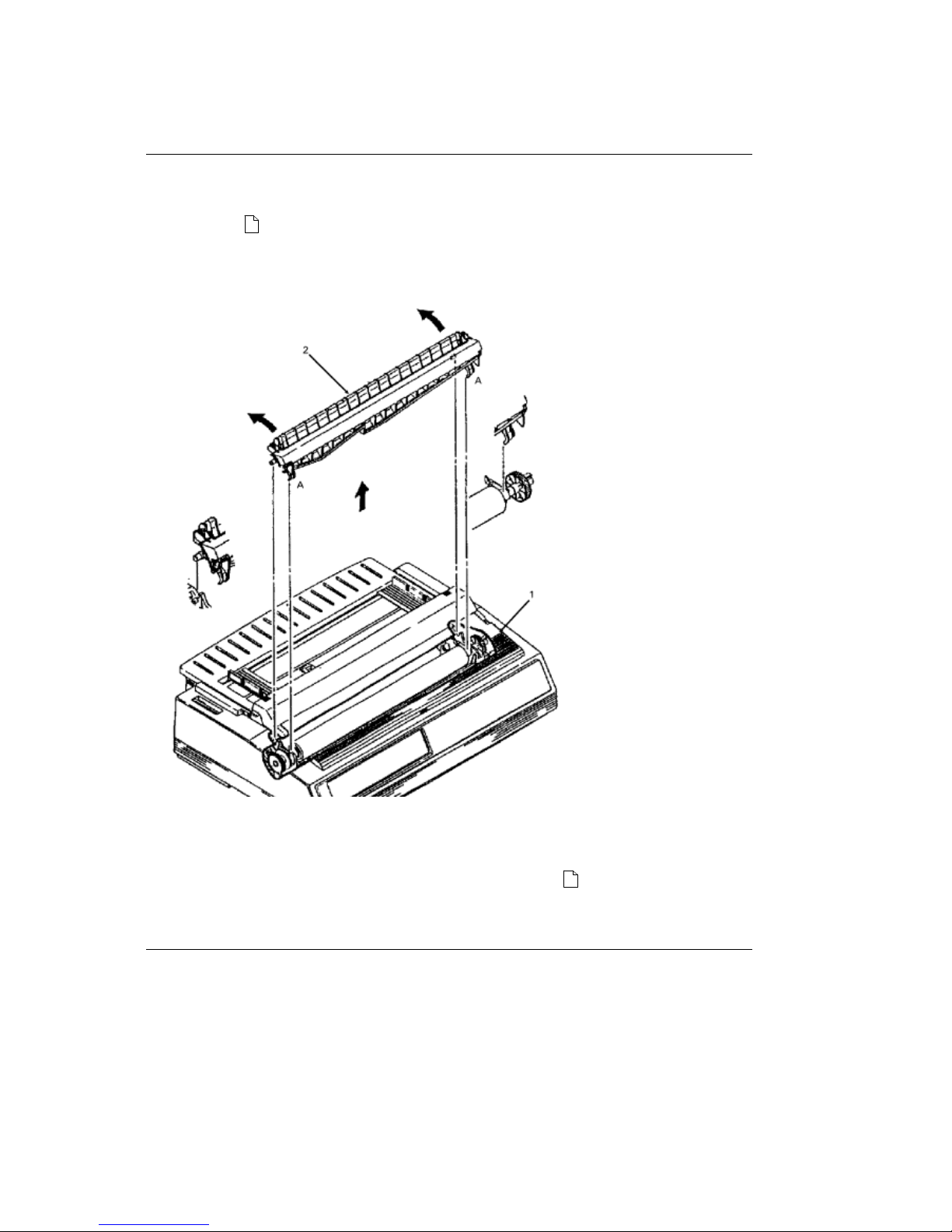
3.2.05 Pull-up Roller Assembly
3.2.05 Pull-up Roller Assembly
1. Perform this procedure:
3.2.01{
}
2. Open the access cover (1).
3. Open the cover of the pull-up roller assembly (2).
4. Press at A while rotating the assembly towards the back of the printer.
5. Remove the assembly.
NOTE:
Lubrication
When lubricating, refer to Section 3.5 of this Service Handbook.{
}
P/N 53341501 Roller: Pull Up Assembly(Narrow) RSPL 590 B.2.04
P/N 53341601 Roller: Pull Up Assembly (Wide) RSPL 591 B.2.04
ML590/591 ( 96-02-07 )
Page 98
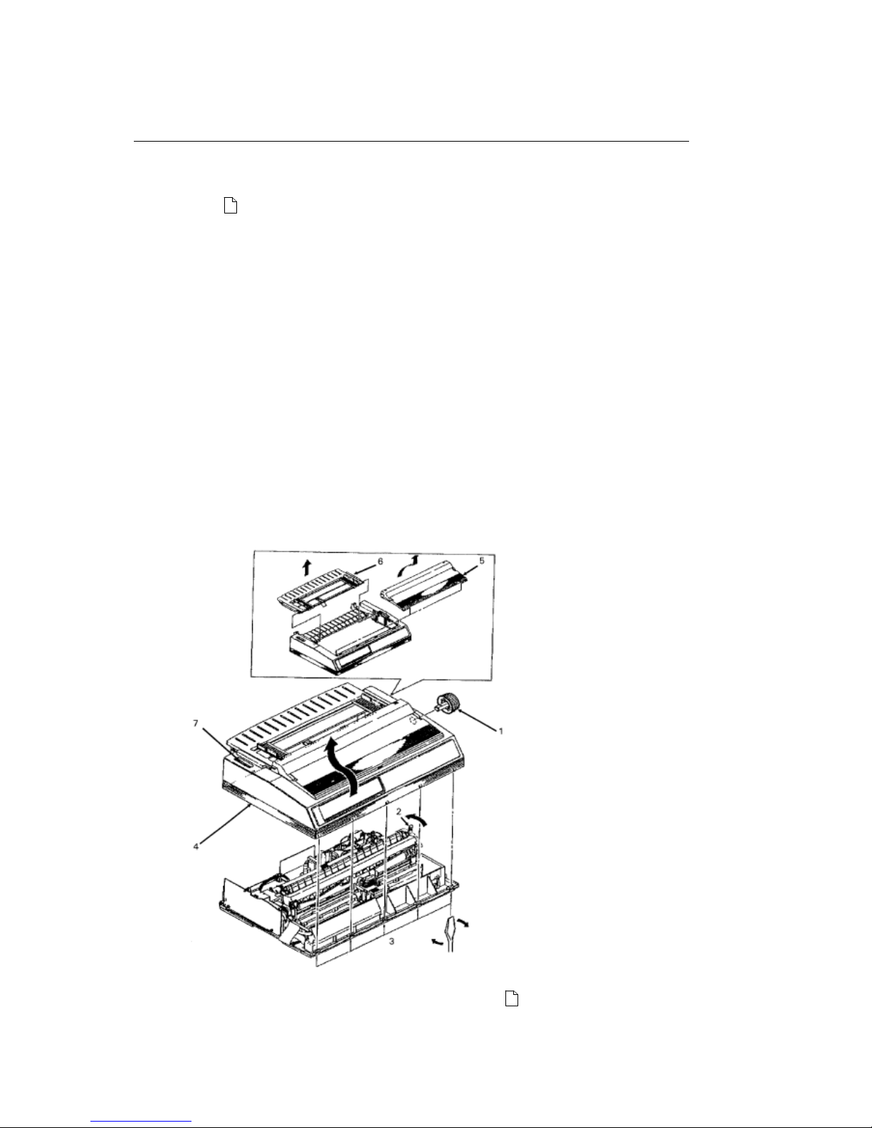
3.2.06 Upper Cover, Access Cover, and Sheet Guide Assemblies
3.2.06 Upper Cover, Access Cover, and Sheet Guide Assemblies
1. Perform this procedure:
3.2.01{
}
2. Pull the platen knob (1) straight out and remove it.
3. Set the change lever (2) to the bottom feed position (toward the rear of the printer).
4. Insert a flat-blade screwdriver into the grooves (3) of the frame and pry the upper cover (4)
away from the frame.
5. Raise the front side of the upper cover assembly.
6. Tilt the upper cover assembly toward the rear to disengage the claws (not shown) at the rear
of the frame.
7. Lift the upper cover assembly and remove it.
CAUTION:
Do not rotate the access cover past the vertical when removing it or you will break the tab
extensions.
8. Raise the access cover assembly (5) until it is vertical, then lift it straight up to remove it.
9. Remove the sheet guide assembly (6).
10. Note the position of the cover (B) <for card slot> (7). This is part of the upper cover and
should not be removed. No font cards are currently available.
NOTE:
When cleaning, refer to Section 3.4 of this Service Handbook.{
}
ML590/591 ( 96-02-07 )
Page 99
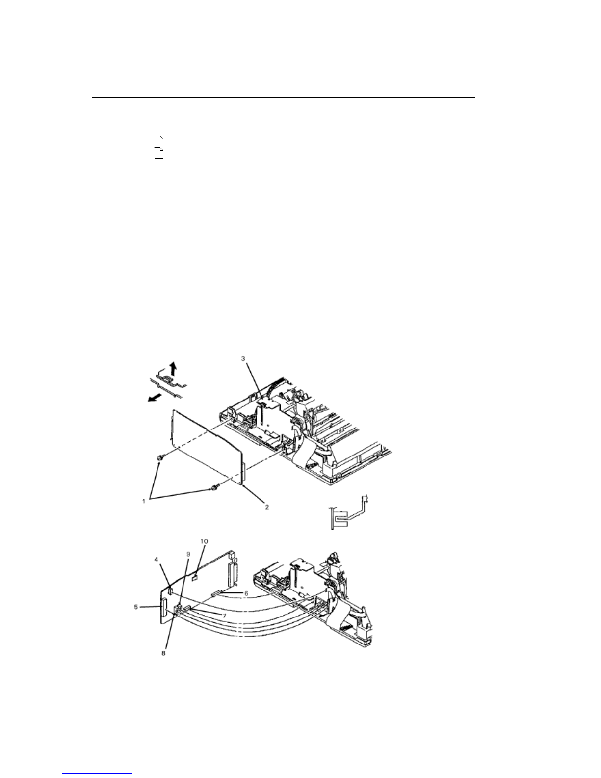
3.2.07 Control Board (AKGI)
3.2.07 Control Board (AKGI)
1. Perform these procedures:
3.2.01{
}
3.2.06{
}
2. Remove the two screws (1).
3. Release the control board (AKGI) (2) from the bracket (3).
4. Tilt the board to access the connectors.
5. Detach connectors CN7 - operator panel (4), CN8 - carriage cable (5), CN3 - power supply
(6), and CN6 - line feed motor (7).
6. Remove the board.
NOTE:
Installation:
The bottom sensor lever must be positioned in the SNS3 sensor (8).
The rear sensor lever must be positioned in the SNS1 sensor (9).
The cut sheet/continuous sensor lever must be positioned below the BASW sensor (10). The
lever should contact the sensor only when the change lever is in the top feed (middle) setting.
The IC: EEPROM is soldered in on the board.
P/N 55937401 PCB: AKGI (w/o ROM) RSPL Both B.2.02
P/N 55938301 IC: EEPROM BR93CC46A RSPL Both B.2.02
ML590/591 ( 96-02-07 )
Page 100
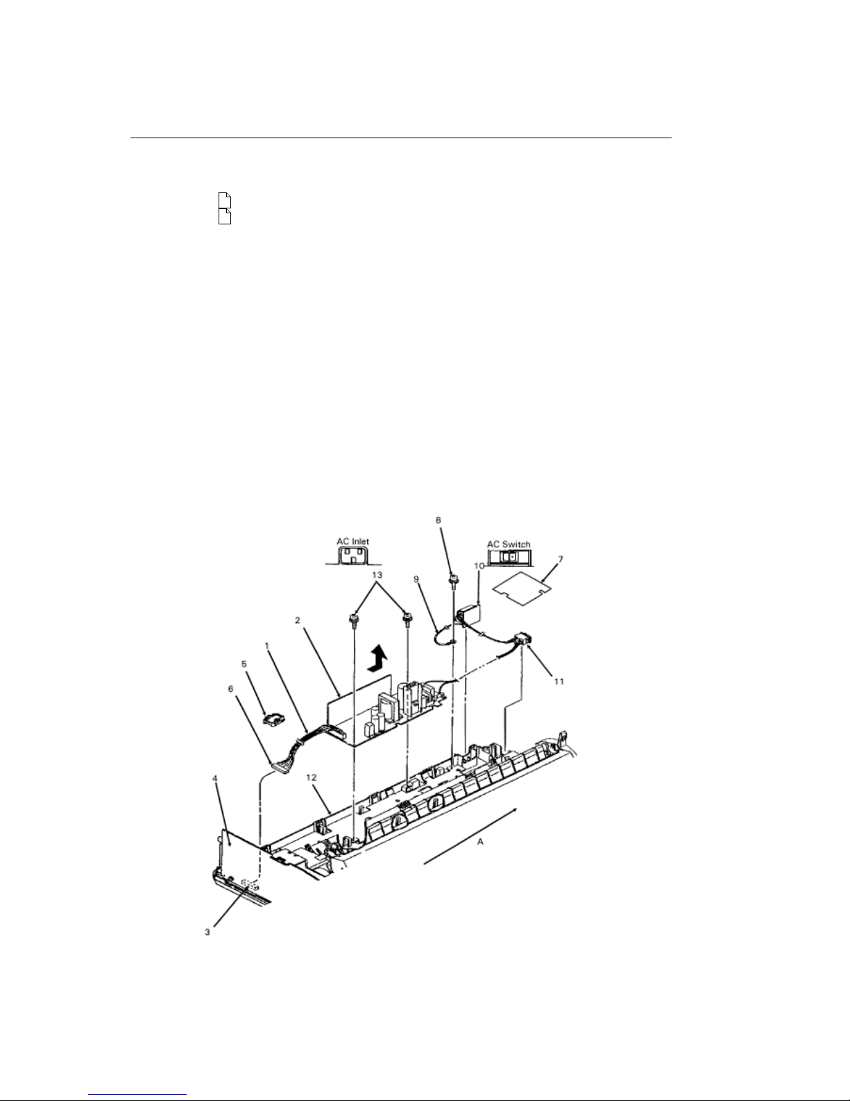
3.2.08 Power Supply Assembly
3.2.08 Power Supply Assembly
Perform these procedures:
3.2.01{
}
3.2.06{
}
1. Detach the cable from connector CN2 (1) of the power supply board (2).
2. Detach the cable from connector CN3 (3) of the control board (4).
3. Use a straight slot screwdriver to release the claws and remove the cable clamp (5).
4. Remove the cable (6).
5. Release the tab and remove the cover (7).
6. Remove the screw (8) and detach the ground cable (9).
7. Lift the AC inlet (10) and the AC switch (11) from the main frame (12).
8. Remove the two screws (13).
9. Slide the power supply in the direction of arrow A to clear the claws of the base frame.
10. Lift and remove the power supply assembly.
NOTE:
The 5 amp fuse is on the end of the board facing the AC inlet and the AC switch.
The 2.5 amp fuse is near the middle of the board.
When installing, verify that the AC inlet and AC switch are oriented correctly.
P/N 50707501 Clamp: Cord RSPL Both B.2.02
P/N 56302901 Fuse: 2.5A 120V RSPL Both B.2.02
ML590/591 ( 96-02-07 )
 Loading...