

Page 1
EN
WatchBP O3
Transferring and deleting measurement data
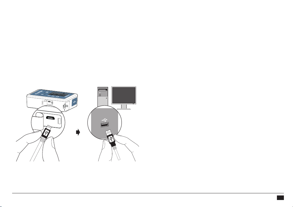
Transferring measurement data
Connect the device to the PC. Start the software program.
Click <Download> and follow the procedure of the
WatchBP Analyzer to transfer the measurement data to a
computer.
Deleting measurements
The measurement data on the device will be
automatically deleted after clicking <Program Device>
in the WatchBP Analyzer software to program a
measurement schedule for the next patient.
See instruction manual of WatchBP Analyzer for details.
23
Page 2
Appendix
“AAA” alkaline batteries are the main power source of the
device.
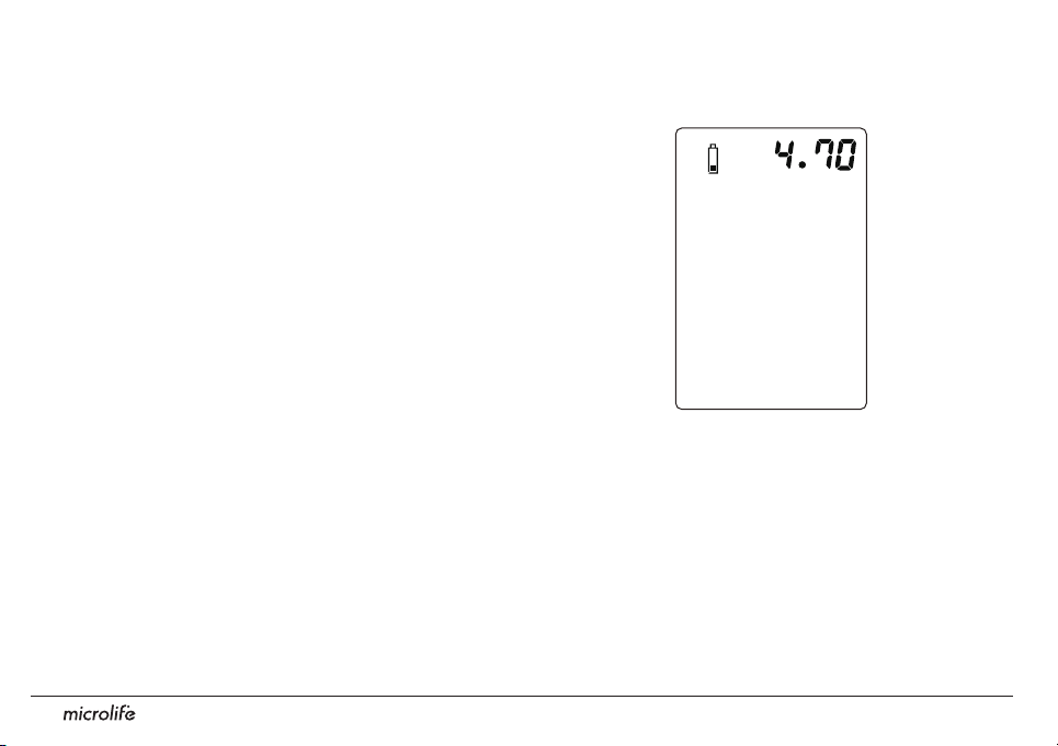
If the voltage is low, the buzzer of the device beeps in order
to remind the user that the batteries need to be replaced.
The buzzer keeps beeping until the batteries are replaced.
The battery icon and voltage number are also displayed
on the LCD screen of the device.
How to replace batteries
Open the battery compartment at the back of the device.
Replace the batteries – ensure correct polarity as shown
by the symbols in the compartment.
Do not use rechargeable batteries.
Use 4 new, 1.5V, size AAA alkaline batteries.
Do not use batteries out of expiration date.
Remove batteries if the device will not be used for a prolonged period.
24
Page 3
EN
WatchBP O3
Bluetooth connectivity
Bluetooth connection of the WatchBP Analyzer
supports Microsoft Windows 10
Regarding the connectivity architecture design, we used
proprietary communication protocol to do data transfer
process. The specific communication protocol is assured
that the information (data) is correct. The program checks
ACK firstly. Afterward, the program compares the received
checksum with the sum of encoded raw data.
If the result is correct, the data is guaranteed during
transmission. In contrast, once the device gets wrong
communication command, it will not have any response.
It is a data encryption and decryption architecture. We
used proprietary encryption method to pack blood
pressure raw data. In other word, Blood Pressure Analyzer
need to use proprietary decryption method to unpack the
encrypted data to get blood
pressure raw data.
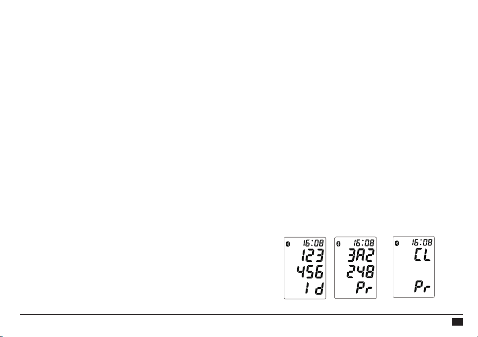
Pairing the device
Press and hold the Start/Stop button for 7 seconds, the
Bluetooth icon flashes and starts pairing mode. The unique 6-
digit device ID of the unit is displayed. Connect the device and
confirm pairing. The Bluetooth icon is displayed on the LCD
screen of the blood pressure monitor to show the presence of
Bluetooth connection.
See the instruction manual of WatchBP Analyzer for details
Please note the following:
Bluetooth is not active when the blood
pressure monitor device is recording data. The blood
pressure monitor device will not sound any alarm
with or without Bluetooth. The Bluetooth is used only
to transfer data from point A to point B.
Press and hold the Start/Stop button for 5 seconds to clear the
connection.
25
Page 4
Safety, care, accuracy test and disposal
Safety and protection
This device may only be used for the purposes as
described in these instructions. The device comprises of
sensitive components and must be treated with caution.
The manufacturer cannot be held liable for damage
caused by incorrect application.
Follow the Instructions for Use. This document provides important
product operation and safety information regarding this Blood Pressure
Monitor. Please read this document thoroughly before using the device
and keep for future reference.
Observe the storage and operating conditions as
described in the “Technical specications” section of this
manual.
Caution: Federal law restrics this device to sale by or on the
order of a physician.
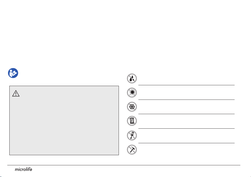
Protect the device from water and moisture
• Ensure that children do not use the device
unsupervised; some parts are small enough to be
swallowed.
• Only activate the pump when the cuff is installed.
• Do not use the device if you think it is damaged or if
anything appears unusual.
• Read the further safety instructions in the individual
sections of the instruction manual.
• Do not connect the device to a computer until
prompted to do so by the computer software.
26
Protect the device from direct sunlight
Protect the device from extreme heat and cold
Avoid proximity to electromagnetic fields, such as
those produced by mobile phones
Never open the device
Protect the device from impact and drops
Page 5
EN
WatchBP O3
M (Medium size) for upper arm
22 - 32 cm (8.7 - 12.6 inches)
With air tube 130 cm
Device care
Use a soft cloth with one of the following recommended
cleaning solutions to wipe the exterior of the device:
• Mild soap and water.
• Hydrogen peroxide solution (3% diluted with water).
• Sodium hypochlorite solution (1:10 dilution of
household chloride bleach in water).
• Isopropyl alcohol (70% solution).
Then wipe the exterior of the device with a soft, dry cloth.
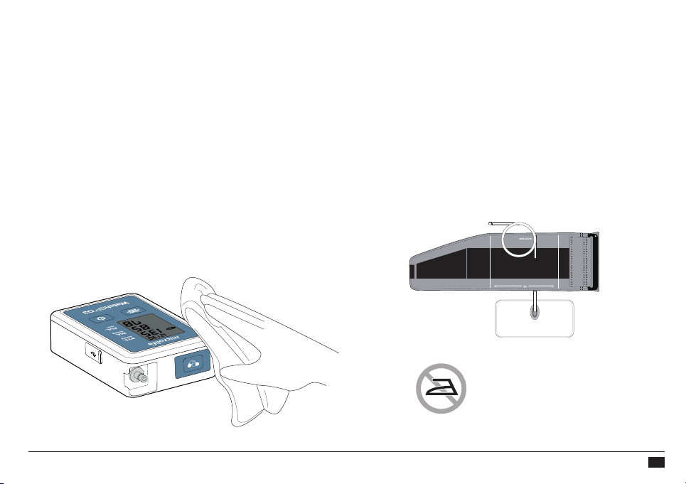
Cleaning the cuff
Take out the bladder. Fold and place the cuff cover
inside a washing bag. Wash the cuff cover with warm
water (43°C; 110°F) and a mild detergent in the
washing machine.
Pasteurization: wash the cuff cover in 75°C(167°F)
hot water for 30 minutes.
Do not iron the cuff!
27
Page 6

Safety, care, accuracy test and disposal
Accuracy test
We recommend the device to be tested for accuracy
every 2 years or after mechanical impact (e.g. Being
dropped). Please contact Microlife to arrange an accuracy
test.
28
Page 7

EN
WatchBP O3
Error messages
If an error occurs during measurement, the measurement
is interrupted and an error message «Er» is displayed.
• The device will take another
measurement automatically
when an error occurs.
• Please consult your doctor,
if this or any other problem
occurs repeatedly.
• If you think the results are
unusual, please read through
the information in this
instruction manual carefully.
Error Description Potential cause and
remedy
"Er 1"
Signal too
weak
The pulse signals on
the cuff are too weak.
Reposition the cuff and
repeat the measurement.
"Er 2"
Error signal
During the measurement,
error signals were
detected by the cuff,
caused for instance by
movement or muscle
tension. Repeat the
measurement, keeping
your arm still.
29
Page 8

Error messages
"Er 3"
"Er 5"
30
No pressure in
the cuff
Abnormal
result
An adequate pressure
cannot be generated
in the cuff. A leak
may have occurred.
Replace the batteries if
necessary. Repeat the
measurement.
The measuring signals
are inaccurate and no
result can therefore
be displayed. Read
through the checklist
for performing reliable
measurements and then
repeat the measurement.
"Er 11"
"Er 12"
Signal too
weak during
central blood
pressure
measurement
Error signal
during central
blood pressure
measurement
The pulse signals on
the cuff are too weak.
Re-position the cuff and
repeat the measurement.
During the measurement,
error signals were
detected by the cuff,
caused for instance by
movement or muscle
tension. Repeat the
measurement, keeping
your arm still.
Page 9

EN
WatchBP O3
"Er 13"
Cuff pressure
errors during
central blood
pressure
measurement
An adequate pressure
cannot be generated
in the cuff. A leak
may have occurred.
Check that the cuff is
correctly connected
and is not too loose.
Replace the batteries if
necessary. Repeat the
measurement.
"Er F"
The device
has gone into
“single fault
condition”
Single fault condition
means that the
measurement is aborted
to protect the patient
from being harmed or
the device from being
damaged.
Re-position the cuff and
repeat the measurement.
Replace the batteries
"Er 15"
Abnormal
result of
central blood
pressure
reading
The measuring signals
are inaccurate and no
result can therefore
be displayed. Read
through the checklist
for performing reliable
"Er A"
Flash memory
error
measurements and then
repeat the measurement.
if necessary. If the error
persists, contact microlife
or the local distributor.
Possible hardware fault.
Try again. If the error
persists, contact Microlife
or the local distributor.
31
Page 10

Error messages
"HI"
"LO"
32
Pulse or cuff
pressure too
high
Pulse too low
The pressure in the cuff
is too high (over 299
mmHg) OR the pulse is
too high (over 239 beats
per minute). Relax for 5
minutes and repeat the
measurement.
The pulse is too low
(less than 30 beats per
minute). Repeat the
measurement.
Page 11

EN
WatchBP O3
Technical specification
Operating
temperature:
Storage temperature:
Weight:
Dimensions:
Measuring procedure:
Method:
Measurement range:
Cuff pressure display:
10 - 40 °C / 50 - 104 °F
•
-20 to 55 °C / -4 to 131 °F
•
15 - 90 % relative maximum humidity
•
240g (including batteries)
•
113 x 77.5 x 33 mm
•
oscillometric, corresponding to
•
Korotkoff
Phase I systolic, Phase V diastolic
•
SYS: 60~255 mmHg
•
DIA: 40~200 mmHg
Pulse: 30 - 239 beats per minute
•
Range: 0 - 299 mmHg
•
Resolution: 1 mmHg
•
Static accuracy: pressure within ±3
•
mmHg
Pulse accuracy: ±5 % of the readout
•
value
Power source:
Expected service life:
Reference to
Standards
• 4X1.5 V Batteries; size AAA
• 2 years
Device corresponds to the
requirements of the standard for noninvasive blood pressure monitor.
EN 1060-1
EN 1060-3
EN 1060-4
IEC 60601-1
IEC 60601-1-2
Microlife reserves the right to alter technical
specifications without prior written notice.
Type BF applied
part
33
Page 12

34
Page 13

Guarantee Card
WatchBP O3
This device is covered by a two-year
guarantee from the date of purchase. This
guarantee is valid only on presentation of
the guarantee card completed by the owner
con rming date of purchase or purchase
receipt. Batteries and wearing parts are not
covered by this guarantee.
Product: WatchBP O3
Product number: BP3SZ1-1
Serial Number:
Date:
Name:
Address:
Date:
Telephone:
Email:
35
EN
Page 14

Distributed by:
Microlife USA, Inc.
1617 Gulf to Bay Blvd
2nd Floor, Suite A Clearwater,
FL 33755, USA Tel. +1 727
442 5353
Fax +1 727 442 5377
Email: msa@microlifeusa.com
www.watchbp.com
IB WatchBP O3 BP3SZ1-1 EN 3819
Page 15

EN
WatchBP O3
37
Page 16

Manufacturer’s Declaration of the Product
(Altogether 4 pages)
Guidance and manufacturer´s declaration – electromagnetic emission –
for all EQUIPMENT AND SYSTEMS
Row
1 Guidance and manufacturer´s declaration – electromagnetic emission
The model BP3SZ1-1(WatchBP O3) is
specified below. The customer or the user of the model BP3SZ1-1(WatchBP O3) should assure
2
that it is used in such an environment.
3 Emissions test Compliance Electromagnetic environment – guidance
RF emissions
4
CISPR 11
RF emissions
5
CISPR 11
Harmonic
emissions
6
IEC 61000-3-2
Voltage fluctuations
/
flicker emissions
7
IEC 61000-3-3
Group 1
Class B
A
Complied
intended for use in the electromagnetic environment
The Model BP3SZ1-1(WatchBP O3) us
for its internal function. Therefore, its RF emissions are
very low and are not likely to cause any interference in
nearby electronic equipment.
The Model BP3SZ1-1(WatchBP O3) is suitable for use
in all establishments, including domestic establishments
and those direc
power supply network that supplies buildings used for
domestic purposes.
tly connected to the public low-voltage
es RF energy only
Page 17

Guidance and manufacturer's declaration – electromagnetic immunity –
for all EQUIPMENT and SYSTEMS
Guidance and manufacturer´s declaration – electromagnetic immunity
The Model BP3SZ1-1(WatchBP O3) are intended for us
specified below. The customer or the user of the Model BP3SZ1-1(WatchBP O3) should assure that it
is used in such an environment.
Immunity test
Electrostatic
discharge (ESD)
IEC 61000-4-2
Electrostatic
transient / burst
IEC 61000-4-4
Surge
IEC 61000-4-5
Voltage dips,
short
interruptions and
voltage
variations
on power supply
input lines
IEC 61000-4-11
Power
frequency
(50/60 Hz)
magnetic field
IEC 61000-4-8
NOTE: UT is the a. c. mains voltage prior to application of the test level.
IEC 60601
test level
± 6 kV contact
±8kVair
± 2 kV for power
supply lines
±1kVfor
input/output
lines
± 1 kV differential
mode
±2kVcommon
mode
<5%UT
(>95 % dip in UT )
for 0.5 cycle
40 % UT
(60%dipinUT)
for 5 cycles
70 % UT
(30%dipinUT)
for 25 cycles
<5%UT
(>95 % dip in UT )
for 5 sec
3A/m
Compliance level
± 6 kV contact
±8kVair
± 2 kV for power
supply lines
± 1 kV for i nput/output
lines
± 1 kV differential mode
± 2 kV common mode
<5%UT
(>95 % dip in UT )
for 0.5 cycle
40 % UT
(60 % dip in UT )
for 5 cycles
70 % UT
(30 % dip in UT )
for 25 cycles
<5%UT
(>95 % dip in UT )
for 5 sec
3A/m
e in the electromagnetic environment
Electromagnetic environment -
guidance
Floors should be wood, concrete or
ceramic tile. If floors are covered
with synthetic material, the relative
humidity should be at least 30 %.
Mains power quality should be that
of a typical commercial or hospital
environment.
Mains power quality should be that
of a typical commercial or hospital
environment.
Mains power quality s
of a typical commercial or hospital
environment. If the user of the
models BP3SZ1-1(WatchBP O3)
product name requires
continued operation during
power mains interruptions, it is
recommended that the models
BP3SZ1-1(WatchBP O3) be
powered from an uninterruptible
power supply or a battery.
Power frequency magnetic fields
should be at levels characteristic of
a typical location in a typical
commercial or hospital
environment.
hould be that
Page 18

Guidance and MANUFACTURER’S declaration – electromagnetic IMMUNITY – for ME
EQUIPMENT and ME SYSTEMS that are not LIFE-SUPPORTING
Guidance and manufacturer’s declaration – electromagnetic immunity
The BP3SZ1-1(WatchBP O3) is intended for use in the electromagnetic environment specified below. The
ustomer or the user of the BP3SZ1-1(WatchBP O3) should assure that it is used in such an environment.
c
Immunity test IEC 60601 test
level
Conducted RF
IEC 61000-4-6
3Vrms
150 kHz to 80
MHz
Radiated RF
IEC 61000-4-3
3V/m
80 MHz to 2.5
GHz
Compliance
level
3V
3V/m
Electromagnetic environment - guidance
Portable and mobile RF c
ommunications
equipment should be used no closer to any
part of the Models BP3SZ1-1(WatchBP O3),
including cables, than the recommended
separation distance calculated from the
equation applicable to the frequency of the
transmitter.
Recommended separation distance
where P is the maximum output power rating
of the transmitter in watts (W) according to the
transmitter manufacturer and d is the
recommended separation distance in
metres(m).
Field strengths from fixed RF transmitters, as
determined by an electromagnetic site survey,
a
should be less than the compliance level in
each frequency range
b
Interference may occur in the vicinity of
equipment marked with the following symbol:
NOTE 1 At 80 MHz and 800 MHz, the higher frequency range applies.
NOTE 2 These guidelines may not apply in all situations. Electromagnetic propagation is affected by
absorption and reflection from structures, objects and people.
a
Field s
trengths from fixed transmitters, such as base stations for radio (cellular/cordless) telephones and
land mobile radios, amateur radio, AM and FM radio broadcast and TV broadcast cannot be predicted
theoretically with accuracy. To assess the electromagnetic environment due to fixed RF transmitters, an
electromagnetic site survey should be considered. If the measured field strength in the location in which the
Model BP3SZ1-1(WatchBP O3) are used exceeds the applicable RF compliance level above, the Model
BP3SZ1-1(WatchBP O3) should be observed to verify normal operation. If abnormal performance is
observed, additional measures may be necessary, such as re-orienting or relocating the Model
BP3SZ1-1(WatchBP O3).
b
Over the frequency range 150 kHz to 80 MHz, field strengths should be less than 3 V/m.
Page 19

Recommended separation distances between portable and mobile
RF communications equipment and the EQUIPMENT or SYSTEM -
for EQUIPMENT and SYSTEMS that are not LIFE-SUPPORTING
Recommended separation distances between
portable and mobile RF communications equipment and the model BP3SZ1-1(WatchBP O3)
The Model BP3SZ1-1(Watc
radiated RF disturbances are controlled. The customer or the user of the Model
BP3SZ1-1(WatchBP O3) can help prevent electromagnetic interference by maintaining a minimum
distance between portable and mobile RF communications equipment (transmitters) and the Model
BP3SZ1-1(WatchBP O3)as recommended below, according to the maximum output power of the
communications equipment.
Rated maximum
output of
transmitter
W
0.01 0.12 0.12 0.23
0.1 0.38 0.38 0.73
11.2 1.2 2.3
10 3.8 3.8 7.3
100 12 12 23
For transmitters rated at a maximum output power not listed above the recommended separation distance
d in metres (m) can be estimated using the equation applicable to the frequency of the transmitter, where P
is the maximum output power rating of the transmitter in watts (W) according to the transmitter
manufacturer.
NOTE 1 At 80 MHz and 800 MHz, the separation distance for the higher frequency range applies.
hBP O3) is intended for use in an electromagnetic environment in which
Separation distance according to frequency of transmitter
m
150 kHz to 80 MHz
5.3
d ]
[
P
V
1
80 MHz to 800 MHz
5.3
d ]
[
P
E
1
800 MHz to 2.5 GHz
7
d ]
P
[
E
1
NOTE 2 These guidelines may not apply in all situations. Electromagnetic propagation is affected by
absorption and reflection from structures, objects and people.
Page 20

38
 Loading...