


P/N: 28180021306
Manufactured in Taiwan
User’s Manual
4CH/ 8CH/ 16CH
Digital Surveillance Stand-Alone System
PART II

FCC NOTICE
This device has been tested and found to comply with the limits for a Class B digital device, pursuant to Part 15 of the FCC Rules.
These limits are designed to provide reasonable protection against harmful interference in a commercial, industrial or business
environment. This equipment can generate, use and radiate radio frequency energy and, if not installed and used in
accordance with the instruction, may cause harmful interference to radio communications. However, there is no guarantee that
interference will not occur in a particular installation. If this equipment does cause harmful interference to radio or television
reception, which can be determined by turning the equipment off and on, the user is encouraged to try to correct the interference
by one or more of the following measures:
Reorient or relocate the receiving antenna.
Increase the separation between the equipment and receiver.
Connect the equipment into an outlet on a circuit different from that to which the receiver is connected.
Consult the dealer or an experienced radio/TV technician for help.
This device complies with Part 15 of the FCC Rules. Operation is subject to the following two conditions: (1) this device may not
cause harmful interference, and (2) this device must accept any interference received, including interference that may cause
undesired operation.
CAUTION ON MODIFICATIONS
All cables used to connect the computer and peripherals must be shielded and grounded. Operation with non-certified
computers or non-shielded cables may result in interference to radio or television reception.
Any changes or modifications not expressly approved by the grantee of this device could void the user’s authority to operate the
equipment.
CE NOTICE
This is a Class B product.
DISCLAIMER
No warranty or representation, either expressed or implied, is made with respect to the contents of this documentation, its quality,
performance, merchantability, or fitness for a p articular purpose. Information presented in this documentation has been carefully
checked for reliability; however, no responsibility is assumed for inaccuracies. The information contained in this documentation
is subject to change without notice.
In no event will MicroJack Multimedia, Inc. be liable for direct, indirect, special, incidental, or consequential damages arising out
of the use or inability to use this product or documentation, even if advised of the possibility of such damages.

TRADEMARKS
MicroJack is a registered trademark of MIT Computer Supplies Co. Ltd. IBM PC is a registered trademark of International
Business Machines Corporation.
Microsoft is a registered trademark and Windows is a trademark of Microsoft Corporation. All other products or corporate
names mentioned in this documentation are for identification and explanation purposes only, and may be trademarks or
registered trademarks of their respective owners.
COPYRIGHT
®2006 by MicroJack Multimedia, Inc. All rights reserved. No part of this publication may be reproduced, transmitted, transcribed,
stored in a retrieval system, or translated into any language in any form by any means without the written permission of
MicroJack Multimedia, Inc.
LIMITED WARRANTY
MicroJack Multimedia, Inc. warrants that this product to be free of defects resulting from faulty manufacturing or components
under the following terms:
WARRANTY LENGTH
Labor is warranted for 12 months from the date of purchase.
Replacement products will be warranted for the remainder of the 12-months warranty period or 30 days, whichever is longer.
WHO IS PROTECTED
This warranty is enforceable only by the first consumer purchaser.
WHAT IS AND IS NOT COVERED
Except as specified below, this warranty covers all defects resulting from faulty manufacturing of this product. The following are
not covered by the warranty.
1. Any product on which the serial number has been defaced, modified, or removed.
2. Damage, deterioration, or malfunction resulting from:
A. Accident, abuse, misuse, neglect, fire, water, lightning, or other acts of nature, commercial or industrial use,
unauthorized product modification, or failure to follow instructions included with the products.
B. Misapplication of service by someone other than the manufacturer’s representative.
C. Any shipment damages. (Claims must be made with carriers.)
D. Any other cause that does not relate to a product defect.
3. Cartons, cases, batteries, cabinets, tapes, or accessories used with products
4. MicroJack Multimedia, Inc, does not warrant that this product will meet your requirements; it is your responsibility to
determine the suitability of this product for your purpose.

WHAT WE WILL AND WILL NOT PAY FOR
We will pay labor and material expenses for covered items. However we will not pay for the following:
1. Removal or installation charges.
2. Shipping charges
3. Any incidental charges
EXCLUSION OF DAMAGES
THE MANUFACTURER’S SOLE OBLIGATION AND LIABILITY UNDER THIS WARRANTY IS LIMITED TO THE REPAIR OR
REPLACEMENT OF A DEFECTIVE PRODUCT AT OUR OPTION. THE MANUFACTURER SHALL NOT, IN ANY EVENT, BE
LIABLE TO THE PURCHASER OR ANY THIRD PARTY FOR ANY INCIDENTAL OR CONSEQUENTIAL DAMAGE (INCLUDING,
BUT NOT LIMITED TO, DAMAGES RESULTING FROM INTERRUPTION OF SERVICE AND LOSS OF BUSINESS) OR
LIABILTY LIMITATIONS OF IMPLIED WARRANTIES.
There are no other oral or written warranties, expressed or implied, including but not limited to
those of merchantability or fitness for a particular purpose. Any implied warranties are limited in
duration to 15 months from the date of purchase.
STATE LAW AND YOUR WARRANTY
This warranty gives you specific legal rights, and you may also have other rights granted under state law. These rights vary from
state to state.
WARRANTY REGISTRATION
Please go to www.microjack.com , under Support -> Warranty to register your warranty.
CONTACT INFORMATION
Phone: 716-236-0009
Address: 8676 Buffalo Ave. Niagara Falls, NY 14304
Web site: www.microjack.com

Table of Contents
CHAPTER 1 INTRODUCTION 3
1.1 Package contents…………………………………….……………………………………………………………………1
1.1.1 Included Item
……………………………………………………………………………………….……………………………1
1.1.2 Optional items….…………………...……………………………………………………….……………………….…………1
1.2 Specifications……………………….…………………………………………………………………………………..…...2
1.3 Major Features………………………………………………………………………………………….…………………...3
1.4 Manual Conventions………………………………………………………………………………………………….…….3
CHAPTER 2 HARDWARE INTRODUCTION 4
2.1 Front Panel…...………………………….………………………………………………………………………… ………..4
2.1.1
Keypad Control……………………………………………………………………………………………………….4
2.1.2
Mouse Control………………………………..……………………………………………… ……………………...4
2.1.3 Buttons Descriptions…………………………………………………………………………………………………5
2.2 Rear Panel..............................................................................................................................................................6
2.3 75Ω Termination Dip-Switch Setting………………………………………………………………………………………8
CHAPTER 3 INSTALLATION AND SETUP 9
3.1 Installation Flow Chart…………………………………………………………………………………………………..….9
3.2 Tool and Equipment Needed to be Prepared in Advance……………………………………………………………..10
3.3 Hard Disk Space Check…….…………………………………………………………………………………………….12
3.4 Take Out Hard Disk for Replacement…………..……………………………………………………………………….12
3.5 On Screen Display (OSD) SETUP ………………………………………………………………………………………13
4CH DVR...............................................................................................................................................................13
8CH DVR...............................................................................................................................................................14
16CH DVR..............................................................................................................................................................15
CHAPTER 4 GENERAL OPERATIONS 16
4.1 Change Screen Display and Activate SEQ Under Live Mode… ………………… ……………… …………………...16
4.2 PTZ Setup………………………………………………………………………………………………………………….17
4.3 Motion Area Setup…………………………………………………………………………………………………………18
4.4 REC Schedule Setup……………………………………………………………………………… ……………………...18
4.5 Confirm Alarm Buzzer………………………… ……………………………… …………………… ……………………..18
4.6 Playback……………………………………………………………………………………………………………………19
4.7 Date/ Time Search Playback …………………………………………………………………………………………….20
4.8 Alarm/Motion Search Playback…………………………………………………………………………………………..20

CHAPTER 5 OFF-LINE PLAYBACK 21
5.1 Connection Options……………………………………………………………………………………………………….21
5.2 Recommended PC requirement for OFF-LINE viewer software……………………………………………………..22
5.3 Data Transfer Rate Table of Different Interface Port ............................................................................................22
5.4 Install the OFF-LINE viewer software into your PC……………………………………… ……………………………. 23
5.5 Run Off-line Viewer Software…………………………………………………………………………………………….23
5.5.1 AVI Video output...........................................................................................................................................24
5.5.2 Images Printing ............................................................................................................................................24
5.5.3 Image Zooming ............................................................................................................................................25
5.5.4 Alarm Log.....................................................................................................................................................25
5.5.5 Date/ time Search Playback.........................................................................................................................25
CHAPTER 6 REMOTE VIEWER SOFTWARE 26
6.1 Install Remote Viewer Software Into Your PC……………………………………………………………………. …...26
6.2 Run Remote Viewer Software……………………………………………………………………………………………26
6.2.1 Setup ............................................................................................................................................................26
6.2.2 Connect........................................................................................................................................................27
6.2.3 Playback Mode.............................................................................................................................................27
6.2.4 History ..........................................................................................................................................................28
CHAPTER 7 FAQ 29
APPENDIX A: NETWORK SETUP………………………………………………………………………………………….30
APPENDIX B: PTZ CAMERA CONTROLLER SETUP…………………………………………………………………..40
APPENDIX C: DDNS SOLUTION…………………………………………………………………………………………...41

MicroJack Part II DVR 4CH/8CH/16CH User’s Manual
Chapter 1 Introduction
1.1 Package Contents
1.1.1 Included Items
4
1
5
2
6
3
MicroJack Part II Digital Surveillance Stand-Alone System Package includes the following items:
1. 1 MicroJack Part II DVR unit
2. 1 Removable Hard Drive Bay (Hard Drive not included)
3. 1 Power Cable
4. 1 Wired Wheel Mouse
5. 1 User Manual
6. 1 Software CD (includes Off-line Viewer, Remote Viewer and 1 electronic version User Manual)
2
1.1.2 Optional Items
1
MicroJack Part II Digital Surveillance Stand-Alone System Optional Items includes:
1. USB 2.0/IDE Converter Kit
2. BNC to VGA PC/TV Converter Kit

Chapter 1 Introduction
1.2 Specifications
4CH 8CH 16CH
Video Input BNC x 4 BNC x 8 BNC x 16
Loop Through BNC x 4 BNC x 8 BNC x 16
Video Output BNC x 1
Audio Input RCA x 2
Audio Output RCA x 2
PTZ Interface
RS232 interface (please refer to Appendix B)
Network Interface RJ 45 x 1
USB 2.0 Interface YES
Mouse Interface YES
Display Resolution 720x480 (NTSC), 720x576 (PAL)
Display Rate (NTSC/PAL) 120 fps / 100 fps 240 fps / 200 fps 480 fps/ 400 fps
Recording Resolution CIF (360x240) CIF (360x240),
½ D1 (720x240)
CIF (360x240),
½ D1 (720x240)
Recording Rate (max) 120 fps (NTSC), 100 fps (PAL)
Recording Quality Low, Fair, Good, Better, Best
Recording Mode 24hrs, Schedule, Sensor Input/Motion Recording
Camera Title Up to 8 characters
Video Adjustment Color, Contrast, Brightness on each camera
Hard Disk IDE type x 1 (support 80, 120, 160, 200, 250 GB)
Playback Control Fast Forward, Play, Rewind, Speed Up & Down
Search Playback Index Day/Time, Alarm, Motion
System Setup KeyPad Control / Mouse Driven OSD
System Alarm Video loss, Motion, Alarm, Hard Drive Full
Real-Time Clock Built in
Power Source 110/220 V, 50/60 Hz Switching
Power Consumption <30W <40W
Weight <4 kgs (8.9 lbs) <4.5 kgs (10 lbs) <4.6 kgs (10.2 lbs)
Dimensions 425w x 300D x 44H mm (16.74W x 11.82D x 1.74H inches)
Approval CE, FCC
* Specifications are subject to change without notice
- 2 -

MicroJack Part II DVR 4CH/8CH/16CH User’s Manual
1.3 Major Features
Reliable Embedded System Design
Real-time Clock
Proprietary Wavelet Format (DVD Quality)
LIVE Monitoring, Recording, Remote Viewing
Alarm Input & Control Output
Motion Detection (up to 4 zones; 8-level sensitivity adjustment per camera)
512 Event Log
Hard Drive Full Alarm
Password Protection Security
USB (Built-in Port or/ USB Kit) + Off-line proprietary Player software
Connect to any PC via USB2.0
Ease of video search & playback
AVI export to CD, Hard Drive, and Memory Stick …
Remote Viewer supplied
IP Addressable, LAN/WAN/ Internet (static IP)
DDNS solution (please refer to Appendix C)
Multi-channel (1/4/9/16CH) Live View Simultaneously
Remote Playback (date/time search)
Remote Alarm Event Call-back
Viewer software CD included
Swappable Hard Drive with FAT32 file system
1.4 Manual Convention
To make sure that you perform the installation or operation properly, take note of the following symbols used
throughout this Manual.
Caution Message: These messages are to advise you to proceed carefully. Failure to pay
attention could result in damage to the system and may put
personnel and environment at risk.
Informational Message: These messages are intended to provide additional information for
the purpose of clarification
- 3 -
Chapter 2 Hardware Introduction
Chapter 2 Hardware Introduction
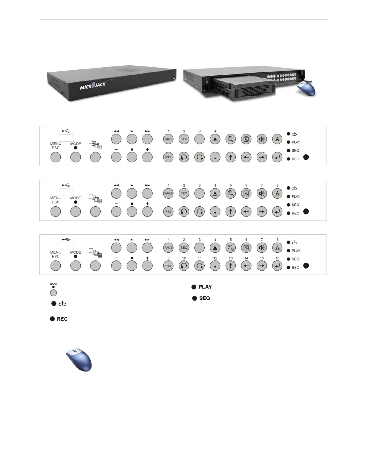
2.1 FRONT PANEL
2.1.1 KEYPAD CONTROL
4CH DVR
USB
8CH DVR
USB
16CH DVR
USB
“MODE” button and LED
“POWER” LED
“REC” LED
“Playback” LED
“Sequence Channel” LED (Live Mode only)
2.1.2 Mouse Control
Left Button: 1. Increase value
2. Enable/Disable Full screen/Quad-screen display
Right Button: 1. Decrease value
2. Switch Page of Screen Display
3. Hide/Call out REC and Playback Mode Control Bar
Press both Left and Right Button: Enter PTZ Setup Page
- 4 -

MicroJack Part II DVR 4CH/8CH/16CH User’s Manual
2.1.3 BUTTONS DESCRIPTIONS
MENU
-On Screen Display (OSD)
Setup
ESC
-Back to the Previous Page
-Back to Live/REC Mode
-Disable Sequence (SEQ)
Change Screen Display
-Enter Playback Mode
-Play
Stop Playback
Rewind During Playback
FF During Playback
Decrease (-) Playback Speed
Increase (+) Playback Speed
4CH 1~4
8CH 1~8
16CH 1~16
-Full Screen Display of the
Selected Channel
-Spot Screen Display of the
Selected Channel (8CH only)
-Alarm Confirmation under Live
Mode
Switch Page of Screen Display
(Press MODE+
)
Enable Sequence Channel
(Press MODE +
)
Remove Hard Drive
(Press MODE+
press
confirm
)
Export video into CF card
during Playback mode
(One file at a time)
Hard disk usage indicator
(Press MODE +
)
Time Search Function in
Playback mode
(Press MODE +
)
Enable/Disable the display title
(Press MODE +
)
Audio Output
(Audio1/Audio2/Off/ Audio1,2)
(Press MODE +
)
Enter
- OSD: Up、Down、Left、Right
- Motion area setup
PTZ Buttons Description (For PTZ feature only) (Press MODE+ )
Down
Up
Left
Right
Auto Pan (Pan left)
Auto Pan (Pan Right)
Zoom Out
Zoom In
Stop
- 5 -
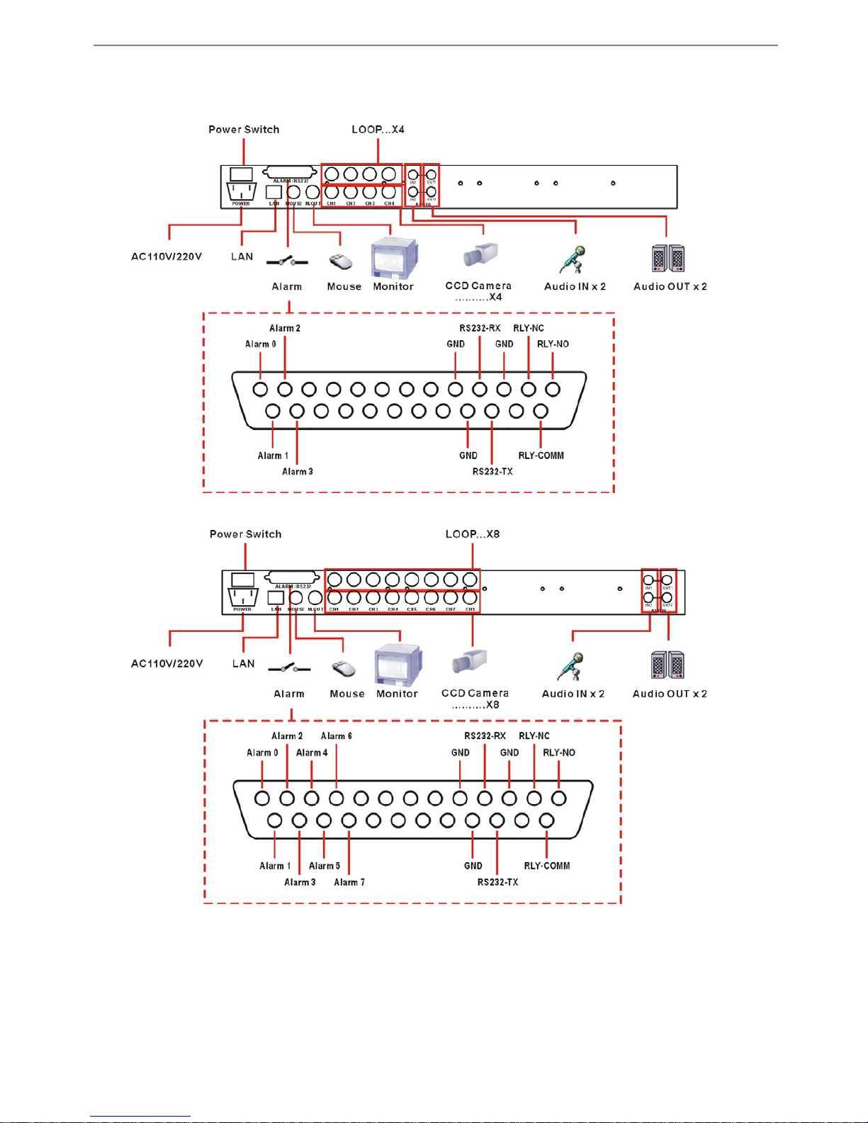
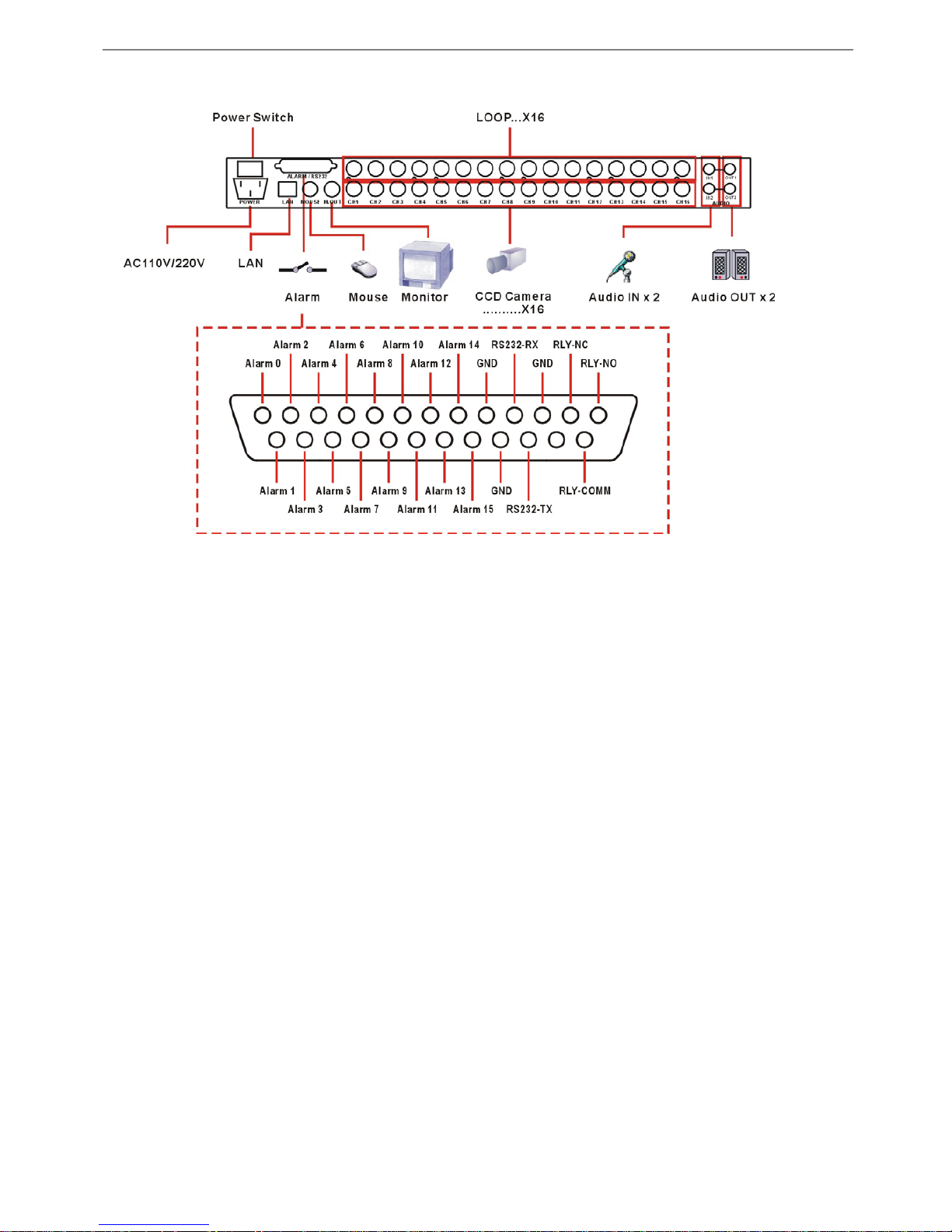
Chapter 2 Hardware Introduction
2.2 REAR PANEL
4CH DVR
8CH DVR
- 6 -
MicroJack Part II DVR 4CH/8CH/16CH User’s Manual
16CH DVR
- 7 -

Chapter 2 Hardware Introduction
2.3 75Ω TERMINATION DIP-SWITCH SETTING
4CH DVR
8CH DVR
16CH DVR
You MUST set 75 ohm dipswitch “OFF” when the LOOP of the camera is connecting to a 3rd device!
Connect to nothing -> 75 ohm termination switch: ON
Connect to camera only-> 75 ohm termination switch: ON
Connect to camera + Loop (Monitor) -> 75 ohm termination switch: OFF
- 8 -

MicroJack Part II DVR 4CH/8CH/16CH User’s Manual
Chapter 3 Installation and Setup
3.1 INSTALLATION FLOW CHART
Prepare a hard disk (HDD),
Maxtor 80/120/160/250GB is recommended
Install Off-line Player to play the
recorded video on PC
Set the 75-ohm dipswitch setting for each channel.
Connect cameras to DVR
Connect the power cable to Power Source
(110~220 V, 50/60Hz); then power on
End
DVR is working properly
Message shown as Fig. 3.1/ 3.2
Parameter (OSD) setting
Insert caddy into HDD slot and lock the HDD
protection key
Install the HDD inside the caddy
- 9 -

Chapter 3 Installation and Setup
3.2 TOOL AND EQUIPMENT NEEDED TO BE PREPARED IN ADVANCE
- Screw driver “+” type
- Hard drive
Maxtor (preferred) or Seagate’s HDD is highly recommended
(80/ 120/ 160/ 250 GB). Hitachi’s 400GB is OK. But Western Digital
is
NOT SUPPORTED. For most updated information about
supported Hard Drive, please refer to our website:
www.microjack.com
Fig. 3.1 (Keypad Control)
4CH DVR 8CH DVR
16CH DVR
2006/01/13 13:58:03
120 REC
Spot Screen
A
larm/ V-Loss/ Motion event will appear on
the screen when alarm is triggered
Alarm
Motion (RED color)
Video Loss (WHITE color)
Press the corresponding channel button on
the front panel to acknowledge the event.
Camera Title
8、16 CH Recording
Rate (FPS)
NTSC PAL
120/60 100/50
32/32 32/24
24/16 24/12
16/8 16/8
8/4 8/4
4 4
4 CH Recording
Rate (FPS)
NTSC PAL
120/60 100/50
60/30 50/25
30/16 25/12
16/8 12/8
8/4 8/4
4 4
- 10 -

MicroJack Part II DVR 4CH/8CH/16CH User’s Manual
Fig 3.2 (Mouse Control)
4CH DVR
OSD Menu Playback Hard Disk Space Remove Hard Disk Audio Control SEQ/ Quad-screen Display
(Audio1/Audio2/Off/ Audio1,2)
8CH DVR 16CH DVR
Status
z REC = Recording
Live = Live Monitoring (No
Recording ongoing)
A
udio Status:
Audio1/Audio2/AudioOFF/
Audio1.2 can be selected
by clicking Audio output
control button
A
larm/ V-Loss/ Motion event will appear
on the screen when alarm detonates
Alarm
Motion (RED color)
Video Loss (WHITE color)
Left click corresponding flashing led to
acknowledge the event.
Camera Title
4 CH Display Rate
(FPS)
NTSC PAL
120/60 100/50
60/30 50/25
30/16 25/12
16/8 12/8
8/4 8/4
44
Spot Screen
Control Bar will be shown only if the mouse is connected before powering on the unit;
Right click to recall the Control Bar .
4CH: SEQ
8CH: 1
st
click = Quad-screen
mode
2
nd
click = SEQ
16CH:1st click = 9-screen
display mode
- 1 1 -

Chapter 3 Installation and Setup
3.3 HARD DISK SPACE CHECK
Keypad Control: Press MODE, then press
;
DVR will show the usage indication bar as
below.
Mouse Control: Left click
on the
screen; DVR will show the usage indication bar
as below.
Note: If your “HDD Full” under Display/Record is set to “STOP,” the message, “HARD is FULL,” will be shown on the
screen and DVR will stop recording until the HDD is replaced or inserted again
3.4 TAKE OUT HARD DISK FOR REPLACEMENT
Keypad Control: Press MODE then press “
“
Don’t remove the HDD until “REMOVE HDD NOW” message is shown.
DVR will keep beeping with the message “INSERT HDD NOW” until you have inserted
the hard disk back for recording.
Mouse Control: Left click
Don’t remove the HDD until “REMOVE HDD NOW” message is shown.
DVR will keep beeping with the message “INSERT HDD NOW” until you have inserted
the hard disk back for recording.
HDD USAGE 41%
INSERT HDD NOW
DVR will keep
beeping after
HDD is
REMOVE HDD NOW
DVR
will keep
beeping after
HDD is
- 12 -

MicroJack Part II DVR 4CH/8CH/16CH User’s Manual
3.5 O
N SCREEN DISPLAY (OSD) SETUP
4CH DVR
Keypad:
Cursor movement
Enter
Mouse Control:
Left click-Increase value
Right click-Decrease value
Administrato
r
Password xxxx
New ID xxxx
Confirm New ID xxxx
Update New ID
Exit
CH1/Title: xxxxxxxx
Bright. : 50
Contr : 50
Color : 50
Hue : 50
Alarm : Off
V_Loss : Off
Motion : Off
PTZ :NULL
Motion Area
Default
Exit
Date/Time
Format :YY/MM/DD
Year : xx
Month : xx
Day : xx
Hour : xx
Min : xx
Sec : xx
Update
Exit
Channel1: channel1
PAGE: 01/01
0 1 2 3 4 5 6 7 8 9 : / _ -- .
! A B C D E F G H I J K L M N O
P Q R S T U V W X Y Z a b c d e
f g h I j k l m n o p q r s t u
Operator’s authority:
- Live View & Playback
(Exclude OSD Setup, HDD
take out, Erase HDD & etc..)
Administrator’s authority
-
A
ll Tasks
v w x y z
Exit
Motion sensitivity: from Off to 08.
Motion Area: The Alarm will be activated once there is motion in the
selected areas.
Motion Area Setup: Please see Chapter 4 General Operation
Display/Record
REC Setting
Title On/Off : OFF (On/Off)
REC Mode : 24hrs (24hrs/Schedule/Trigger)
HDD Full : Cyclic (Cyclic/Stop)
Alarm REC : 10 (01 – 60 secs)
REC Resume : OFF (On/Off)
AUDIO 1 Vol. : OFF (Off/1/2/3/4/5/6/7/8)
AUDIO 2 Vol. : OFF (Off/1/2/3/4/5/6/7/8)
Exit
REC Setting
Quality : Best (Best/Better/Good/Fair/Low)
REC Resolution : CIF
Tota Rate : 120 (120/60/30/16/8/4) l
Exit
Alarm REC: Once the alarm is triggered under
Schedule/Trigger REC Mode, DVR will record any
motion for 01-60 sec after the motion occurred.
When REC Resume is set to “ON” under Playback mode
or Main Menu for more than 5 minutes without any
action, the system will exit to REC mode automatically
The inserted PTZ ID (1-255) has to match with the ID on
the
PTZ.
Password
Password Check: OFF
Administrator
Operator
Exit
Change value
MAIN MENU
Password
Channel 1
Channel 2
Channel 3
Channel 4
Date/Time
Display/Record
Others
Alarm Log
Internet
Exit
Password
Channel 1
Channel 2
Channel 3
Channel 4
Date/Time
Display/Record
Others
Alarm Log
Internet
Exit
Password
Channel 1
Channel 2
Channel 3
Channel 4
Date/Time
Display/Record
Others
Alarm Log
Internet
Exit
Password
Channel 1
Channel 2
Channel 3
Channel 4
Date/Time
Display/Record
Others
Alarm Log
Internet
Exit
Password
Channel 1
Channel 2
Channel 3
Channel 4
Date/Time
Display/Record
Others
Alarm Log
Internet
Exit
Password
Channel 1
Channel 2
Channel 3
Channel 4
Date/Time
Display/Record
Others
Alarm Log
Internet
Exit
Others
Buzzer : ON
Set UART (1200/2400/4800/9600)
DWELL (02-30sec)
Event return:ON/OFF
Setup REC Schedule
Exit
A
larm Log Page (1~64)
MM-DD-HH-MM-SS-CH-TP
12-18-19 -37-02-xxxxx
Xx -xx-xx -xx- xx-xx
Xx -xx-xx -xx- xx-xx
Xx -x
x-xx -xx- xx-xx
Exit
Port IP
TCP :1220
UDP :1350
Default
Exit
Default: user (lower case)
Default: 99999999 (8 digits)
DWELL: The time for each
channel displayed in a sequence
Event Return: when setting ON;
and an alarm being triggered;
DVR will revert back to
multi-divided screen display
(Live)
Schedule
Day: Sun、Mon、Tue、Wed、Thu、Fri、Sat
Time REC Rate Mode
00:00
00:00 OFF 120 BEST
00:00 OFF 120 BEST
00:00 OFF 120 BEST
00:00 OFF 120 BEST
Exit
Setup REC schedule for each day of a week
The initial time 00:00 in the first column
cannot be adjusted.
Insert the desire time schedule in an
ascending order from the top row to the
bottom.
The message “Error” will appear, if the
schedule is not in a consecutive order
E.g. Tuesday 08:00 am - 02:00 pm, the
schedule should be set as:
Time REC Rate Mode
00:00
08:00 OFF 120 BEST
08:01 ON 120 BEST
14:00 ON 120 BEST
14:01 OFF 120 BEST
Internet
Username: user
Password: 99999999
Port IP
IP Address:
192.168.000.100
Sub mask
255.255.255.000
Gateway:
192.168.000.001
Exit
Password
Channel 1
Channel 2
Channel 3
Channel 4
Date/Time
Display/Record
Others
Alarm Log
Internet
Exit
- 13 -

Chapter 3 Installation and Setup
8CH DVR
Keypad Control:
Cursor movement
Others
Buzzer : ON
V – center
Set UART (1200/2400/4800/9600)
DWELL (02-30sec)
Event return:ON/OFF
Setup REC Schedule
Exit
MAIN MENU
Password
Channel 1-2
Channel 3-4
Channel 5-6
Channel 7-8
Date/Time
Display/Record
Others
Alarm Log
Internet
Exit
Title : xxxxxxxx
Bright. : 50
Contr : 50
Color : 50
Hue : 50
Alarm : Off
V_ Loss : Off
Motion : Off
PTZ : NULL
Motion Area
Default
Exit
Channel 1: Camera 1
Channel 2: Camera 2
Exit
Date/Time
Format :YY/MM/DD
Year : xx
Month : xx
Day : xx
Hour : xx
Min : xx
Sec : xx
Update
Exit
A
larm Log Page (1~64)
MM-DD-HH-MM-SS-CH-TP
12-18-19 -37-02-xxxxx
Xx -xx-xx -xx- xx-xx
Xx -xx-xx -xx- xx-xx
Xx -x
x-xx -xx- xx-xx
Exit
Channel1: Channel1
PAGE: 01/01
0 1 2 3 4 5 6 7 8 9 : / _ -- .
! A B C D E F G H I J K L M N O
P Q R S T U V W X Y Z a b c d e
f g h I j k l m n o p q r s t u
v w x y z
Exit
Password
Channel 1-2
Channel 3-4
Channel 5-6
Channel 7-8
Date/Time
Display/Record
Others
Alarm Log
Internet
Exit
Password
Channel 1-2
Channel 3-4
Channel 5-6
Channel 7-8
Date/Time
Display/Record
Others
Alarm Log
Internet
Exit
Password
Channel 1-2
Channel 3-4
Channel 5-6
Channel 7-8
Date/Time
Display/Record
Others
Alarm Log
Internet
Exit
Password
Channel 1-2
Channel 3-4
Channel 5-6
Channel 7-8
Date/Time
Display/Record
Others
Alarm Log
Internet
Exit
Password
Channel 1-2
Channel 3-4
Channel 5-6
Channel 7-8
Date/Time
Display/Record
Others
Alarm Log
Internet
Exit
Password
Channel 1-2
Channel 3-4
Channel 5-6
Channel 7-8
Date/Time
Display/Record
Others
Alarm Log
Internet
Exit
Motion sensitivity: from Off to 08.
Display/Record
Title On/Off : OFF
Quality : Best
REC Mode : 24hrs
REC Resolution : CIF
Total Rate : 120
HDD Full : Cyclic
Alarm REC : 10
REC Resume : OFF
AUDIO 1 GAIN : OFF
AUDIO 2 GAIN : OFF
Exit
(On/Off)
(Best/Better/Good/Fair/Low)
(24hrs/Schedule/Trigger)
(Half-D1/CIF)
(120/32/24/16/8/4)
(Cyclic/Stop)
(01 – 60 secs)
(On/Off)
(Off/1/2/3/4/5/6/7/8) Level 8 is the loudest volume
(Off/1/2/3/4/5/6/7/8) Level 8 is the loudest volume
Alarm REC: Once the alarm is triggered
under Schedule/Trigger REC Mode,
DVR will record any motion for 01-60
sec after the motion occurred.
When REC Resume is set to
“ON” under Playback mode
or Main Menu for more than
5 minutes without any action,
the system will exit to REC
mode automatically.
(DD/MM/YY)
Password
Password Check: OFF
Administrator
Operator
Exit
The inserted PTZ ID
(1-255) has to match
with the ID on the PTZ.
Motion Area: The Alarm will be
activated once there is motion in the
selected areas.
Motion Area Setup: Please see
Chapter 4 General Operation
Change value
Administrato
r
Password xxxx
New ID xxxx
Confirm New ID xxxx
Update New ID
Exit
Enter
Mouse Control:
Left click-Increase value
Operator’s authority:
- Live View & Playback
(Exclude OSD Setup, HDD
take out, Erase HDD & etc..)
Administrator’s authority
-
A
ll Tasks
Right click-Decrease value
Schedule
Day: Sun、Mon、Tue、Wed、Thu、Fri、Sat
Time REC Rate Mode
00:00
00:00 OFF 120 BEST
00:00 OFF 120 BEST
00:00 OFF 120 BEST
00:00 OFF 120 BEST
Exit
Internet
Username: user
Password: 99999999
Setup REC schedule for each day of a week
The initial time 00:00 in the first column
cannot be adjusted.
V-Ce nter : Adjust vertical
position of the screen.
DWELL: The time for each
channel displayed in a
sequence
Event Return: when setting
ON; and an alarm being
triggered; DVR will revert
back to multi-divided screen
dis
play (
Live
)
Insert the desire time schedule in an
ascending order from the top row to the
bottom.
The message “Error” will appear, if the
schedule is not in a consecutive order
E.g. Tuesday 08:00 am - 02:00 pm, the
schedule should be set as:
Time REC Rate Mode
00:00
08:00 OFF 120 BEST
08:01 ON 120 BEST
14:00 ON 120 BEST
14:01 OFF 120 BEST
Default: user (lower case)
Default: 99999999 (8 digits)
Port IP
IP Address:
192.168.000.100
Port IP
TCP :1220
UDP :1350
Default
Exit
Sub mask
255.255.255.000
Gateway:
192.168.000.001
Exit
- 14 -

MicroJack Part II DVR 4CH/8CH/16CH User’s Manual
16CH DVR
Keypad/IR Control:
Cursor movement
Enter
Mouse Control:
Left click-Increase value
Right click-Decrease value
Change value
Others
Buzzer : ON
V – center
Set UART (1200/2400/4800/9600)
DWELL (02-30sec)
Event return:ON/OFF
Setup REC Schedule
Exit
MAIN MENU
Password
Channel 1-4
Channel 5-8
Channel 9-12
Channel 13-16
Date/Time
Display/Record
Others
Alarm Log
Internet
Exit
Title : xxxxxxxx
Bright. : 50
Contr : 50
Color : 50
Hue : 50
Alarm : Off
Password
Password Check: OFF
Administrator
Operator
Exit
Operator’s authority:
- Live View & Playback
(Exclude OSD Setup, HDD
take out, Erase HDD & etc..)
Administrator’s authority
- All Tasks
Administrato
r
Password xxxx
New ID xxxx
Confirm New ID xxxx
Update New ID
Exit
Channel1: Channel1
PAGE: 01/01
0 1 2 3 4 5 6 7 8 9 : / _ -- .
! A B C D E F G H I J K L M N O
P Q R S T U V W X Y Z a b c d e
f g h I j k l m n o p q r s t u
v w x y z
Exit
Password
Channel 1-4
Channel 5-8
Channel 9-12
Channel 13-16
Channel 1: Camera 1
Channel 2: Camera 2
V_ Loss : Off
Motion : Off
PTZ :NULL
Motion Area
Channel 3: Camera 3
Default
Exit
Channel 4: Camera 4
Exit
Date/Time
Format :YY/MM/DD
Year : xx
Month : xx
Day : xx
Hour : xx
Min : xx
Sec : xx
Update
Exit
Display/Record
Title On/Off : OFF
Quality : Best
REC Mode : 24hrs
REC Resolution : CIF
Total Rate : 120
HDD Full : Cyclic
Alarm REC : 10
REC Resume : OFF
AUDIO 1 Vol. : OFF
AUDIO 2 Vol. : OFF
Exit
A
larm Log Page (1~64)
MM-DD-HH-MM-SS-CH-TP
12-18-19 -37-02-xxxxx
Xx -xx-xx -xx- xx-xx
Xx -xx-xx -xx- xx-xx
Xx -x
x-xx -xx- xx-xx
Exit
Date/Time
Display/Record
Others
Alarm Log
Internet
Exit
(On/Off)
(Best/Better/Good/Fair/Low)
(24hrs/Schedule/Trigger)
(Half-D1/CIF)
(120/32/24/16/8/4)
(Cyclic/Stop)
(01 – 60 secs)
(On/Off)
(Off/1/2/3/4/5/6/7/8) Level 8 is the loudest volume
(Off/1/2/3/4/5/6/7/8) Level 8 is the loudest volume
Motion Area: The Alarm will be
activated once there is motion in the
selected areas.
Motion Area Setup: Please see Ch4
General Operation
Motion sensitivity: From Off to 08.
The inserted PTZ ID
(1-255) has to match
with the ID on the PTZ.
Internet
Username: user
Password: 99999999
Port IP
Default: user (lower case)
Default: 99999999 (8 digits)
Port IP
TCP :1220
UDP :1350
Default
Exit
Setup REC schedule for each day of a week
The initial time 00:00 in the first column
cannot be adjusted.
Insert the desire time schedule in an
ascending order from the top row to the
bottom.
The message “Error” will appear, if the
schedule is not in a consecutive order
E.g. Tuesday 08:00 am - 02:00 pm, the
schedule should be set as:
Time REC Rate Mode
00:00
08:00 OFF 120 BEST
08:01 ON 120 BEST
14:00 ON 120 BEST
14:01 OFF 120 BEST
Schedule
Day: Sun、Mon、Tue、Wed、Thu、Fri、Sat
Time REC Rate Mode
00:00
00:00 OFF 120 BEST
00:00 OFF 120 BEST
00:00 OFF 120 BEST
00:00 OFF 120 BEST
Exit
V-Ce nter : Adjust vertical position
of the screen.
DWELL: The time for each
channel displayed in a sequence
Event Return: when setting ON;
and an alarm being triggered;
DVR will revert back to
multi-divided screen display
IP Address:
192.168.000.100
Sub mask
255.255.255.000
Gateway:
192.168.000.001
Exit
When REC Resume is set
to “ON” under Playback
mode or Main Menu for
more than 5 minutes
without any action, the
system will exit to REC
mode automaticall
y
.
Alarm REC: Once the alarm is
triggered under Schedule/Trigger REC
Mode, DVR will record any motion for
01-60 sec after the motion occurred.
Password
(DD/MM/YY)
Channel 1-4
Channel 5-8
Channel 9-12
Channel 13-16
Date/Time
Display/Record
Others
Alarm Log
Internet
Exit
Password
Channel 1-4
Channel 5-8
Channel 9-12
Channel 13-16
Date/Time
Display/Record
Others
Alarm Log
Internet
Exit
Password
Channel 1-4
Channel 5-8
Channel 9-12
Channel 13-16
Date/Time
Display/Record
Others
Alarm Log
Internet
Exit
Password
Channel 1-4
Channel 5-8
Channel 9-12
Channel 13-16
Date/Time
Display/Record
Others
Alarm Log
Internet
Exit
Password
Channel 1-4
Channel 5-8
Channel 9-12
Channel 13-16
Date/Time
Display/Record
Others
Alarm Log
Internet
Exit
- 15 -

Chapter 4 General Operations
Chapter 4 General Operations
4.1 CHANGE SCREEN DISPLAY AND ACTIVATE SEQ UNDER LIVE MODE
Keypad Control:
Screen Display:
Press
to switch the screen display one at a time, then press MODE+ to switch page of
screen display:
4CH: Quad-screen → Full screen display → Back to Quad-screen display
8CH: 8-screen display → Quad-screen (2 pages) → Back to 8-screen display
16CH: 16-screen display → 9-screen (2 pages) → Quad-screen (4 pages) → Back to 16-screen
display
Press the corresponding channel buttons for full-screen display.
SEQ Display:
Press MODE+
to activate SEQ. SEQ display order as below: (press ESC to exit SEQ)
4CH: 1st Full → 2nd Full → 3rd Full → 4th Full → Quad → (Repeat)
8CH: 1st Full → 2nd Full → 3rd Full → (Continue to 8th Full) → 8-screen → (Repeat)
16CH: 1st Full → 2nd Full → 3rd Full → (Continue to 16th Full) → 16-screen → (Repeat)
Mouse Control:
Screen Display and SEQ Display:
1. The button
contains screen-display and SEQ features. Left click
to switch the
screen display one at a time, and activate SEQ display. Display order as below:
4CH: Quad-screen (see *1) → SEQ → Back to Quad-screen display
8CH: 8-screen display → Quad-screen (2 pages, see *1, **2) → SEQ → Back to 8-screen display
16CH: 16-screen display →9-screen display (2 pages, see*1, **2) → Quad-screen (4 pages, see *1,
**2) → SEQ →Back to 16-screen display
*1.Left click on the selected camera for Full-screen display
**2. Right click to switch page.
2. Click
once for 4CH, click twice for 8CH, click thrice for 16CH to activate SEQ
display. The display order is the same as keypad control:
4CH: 1st Full → 2nd Full → 3rd Full → 4th Full → Quad → (Repeat)
8CH: 1st Full → 2nd Full → 3rd Full → (Continue to 8th Full) → 8-screen → (Repeat)
16CH: 1st Full → 2nd Full → 3rd Full → (Continue to 16th Full) → 16-screen → (Repeat)
- 16 -

MicroJack Part II DVR 4CH/8CH/16CH User’s Manual
4.2 PTZ S
ETUP
Keypad Control:
1. Press MODE, then press
to enter PTZ setup menu of Ch1.
2. Change PTZ position by pressing
.
Press
for pan right. Press for pan left. Press any button to stop.
Press
to zoom in/out.
3. To switch channel, Press MODE and the desired channel button
4. Repeat step 2 to adjust PTZ setting
5. Press ESC to exit back to the original REC screen display.
Please make sure your PTZ ID under the menu corresponds to the ID number on the PTZ.
Mouse Control:
1. Under live original screen display, click both right and left button at once to call out PTZ setup page, and
then choose the desired channel.
OR, under full-screen display of the selected camera (left click desired camera for full screen), click both
right and left button at once to call out PTZ setup control bar.
MOUSE PTZ Control Bar
+\-
■
▼ ▲ ◄ ► EXIT
For more information about connecting the PTZ camera through RS232/485 controller, please refer to
Appendix B
- 17 -

Chapter 4 General Operations
4.3 MOTION AREA SETUP
Keypad Control: (Please refer to Section 3.5 the OSD Setup)
1. Select “Motion Area” under the selected camera. The previous Motion Area setting will be shown on the
screen.
2. Use
to move the cursor to the beginning (upper left) point of the wanted detection zone
then press
for confirmation
3. Move the cursor to the end (right bottom) point of the zone; then press
for confirmation.
4. Repeat step 2, step 3 to have up to four (4) zones
5. Press
to complete the motion setup
(“Motion setup OK!” will be shown on the screen)
6. Adjust Alarm REC if your DVR is not in 24-hr REC Mode
7. Video Motion Detection (VMD) function will be enabled ONLY if the “Motion” has been turned to ON; and
one (minimum) detection zone has been set up.
Mouse Control: (Please refer to Section 3.5 the OSD Setup)
1. Select “Motion Area” under the selected camera. The previous Motion Area setting will be shown on the
screen.
2. Use the mouse to select the wanted detected zone from the beginning (upper left) to the end (right b ottom).
3. Repeat step 2 to select up to four zones
4. Right click the mouse for confirmation
(“Motion setup OK!” will be shown on the screen)
5. Adjust Alarm REC if your DVR is not in 24-hr REC Mode
6. VMD will be enabled ONLY if the “Motion” has been turned to ON; and one (minimum) detection zone has
been set up.
4.4 REC S
CHEDULE SETUP
Please make sure your REC Mode under Display/Record is in Schedule mode (not 24hrs or Trigger), and set
the desired recording time into Setup REC Schedule under Others
4.5 CONFIRM ALARM BUZZER
Once the alarm has been triggered, the screen will switch back to the original screen display.
Keypad Control: Push the button with the corresponding channel number to acknowledge the alarm and
disable the alarm buzzer.
Mouse Control: Left click on the screen of corresponding channel number to acknowledge the alarm and
disable the alarm buzzer.
- 18 -

MicroJack Part II DVR 4CH/8CH/16CH User’s Manual
4.6 PLAYBACK
Keypad Control:
Press
button to activate Playback mode. Use the buttons on the front panel to adjust playback status.
Press the corresponding channel buttons for full-screen display.
8CH: Press MODE+ to switch page of screen display.
16CH: Press
to enable/disable quad-screen display and press MODE+
to switch page
Mouse Control: Click button to activate Playback mode. Click on the buttons on the control bar to
adjust playback status.
Playback Status
Stop
Play
(+) / (-) (+) / (-) Speed
Fast Rewind 2x -16x
Fast Forward 2x -16x
120
Playback Status
Stop
Play
(+) / (-) (+) / (-) Playback speed
Rewind (2X/4x/8x/16X)
Fast Forward (2X/4x/8x/16X)
A
udio Status:
Audio1/Audio2/AudioOFF/Audio1.
2 can be selected under the
REC/Live Status when pressing
Audio output control
Increase (+) left click mouse
Decrease (-) Right click mouse
Playback Speed
Fast Forward
2X/4X/8X/16X
A
udio Output Control
Stop
Exit
Time Search
Playback
Playback
Rewind
2X/4X/8X/16X
Quad-screen Display
16CH Series ONLY
Left Click
to switch screen display
Left Click on the desired camera for full screen
Right Click to switch page
- 19 -

Chapter 4 General Operations
4.7 DATE/ TIME SEARCH PLAYBACK
Keypad Control: Press MODE, then press on the front panel.
TIME SEARCH
MM-DD HH:MM:SS
12-08 15:05:04
“WAITING for SEARCH now”
¼ DVR is searching video now
“FILE NOT EXIT”
Enter
Exit
START TIME
¼ No recorded video is found
YY-MM-DD HH-MM-SS
END TIME
YY-MM-DD HH-MM-SS
Mouse Series: Enter Playback Mode and click to enter Date/Time Search Playback.
Operation:
1. Move the cursor to the date/ time you want to change the
value
- Left button of the mouse: increase the value
- Right button of the mouse: decrease the value
2. Move the cursor to “Enter”
3. LEFT click to start the video search
“WAITING for SEARCH now”
¼ DVR is searching video now
“FILE NOT EXIT”
¼ No recorded video is found
4.8 A
LARM/MOTION SEARCH PLAYBACK
Once an alarm has occurred, the date/time will be saved to Alarm Log. Enter the OSD main menu and select
Alarm Log (Please refer to OSD Setup Chapter).
Keypad Control:
Mouse Control:
Note: There is no “Time Search” under Alarm Log playback mode
A
larm Log Page (1~64)
MM-DD-HH-MM-SS-CH-TP
12-18-19 37-02 xx-xx
xx-xx-xx xx-xx xx-xx
xx-xx-xx xx-xx xx-xx
xx-xx-xx xx-xx xx-xx
xx-xx-xx xx-xx xx-xx
Exit
1. Select the alarm you want to playback
2. Left click to playback the selected alarm video
Operation
Move the cursor
or
Playback
- 20 -

MicroJack Part II DVR 4CH/8CH/16CH User’s Manual
Chapter 5 OFF-LINE PLAYBACK
5.1 CONNECTION OPTIONS
1. Via IDE interface
Step 1: Make sure the installed HDD caddy (drawer) is compatible with the following: BT-27, BT-32, BT-42,
RH-17, RH-27, RH-32, RH-42, MR-27 or L-007.
Step 2: Power-off PC before inserting the hard drive with drawer directly into the PC
Step 3: Power on the PC and run the supplied off-line player to play back the recorded files
If your PC cannot recognize the HDD, please change the hard disk jumper configuration. (Master only)
Internal HDD caddy (Drawer) is compatible
with one of following:
BT-27, BT-32, BT-42, RH-17, RH-27, RH-32,
RH-42, MR-27 and L-007
2. Via built-in USB2.0 interface
Make the USB2.0 connection between the USB 2.0 port & the PC
3. Via USB2.0/IDE converter (Optional item purchased from local distributor or PC peripheral supplier)
Step 1: Plug the USB2.0/IDE converter into the IDE socket of the mobile drawer properly
Step 2: Connect the USB2.0 converter to PC with the USB2.0 cable
Step 3: Power on the USB2.0 converter then run the off-line player
Please complete Step 1 before powering on the USB2.0 converter to prevent unnecessary HDD
damage. Please keep the jumper configuration of hard disk in “Master Mode”.
USB2.0 Kit Package includes:
- USB2.0/IDE converter
- USB2.0 cable
- 90-240 V power adaptor for
USB2.0/IDE converter
- Driver Setup Disk
- Removable HDD with caddy
- 21 -

Chapter 5 Off-Line Playback
5.2 RECOMMENDED PC REQUIREMENTS FOR OFF-LINE VIEWER SOFTWARE
Your PC should have the following specifications to use the off-line player software.
CPU: P3 1.0 GHz or above (preferred P4)
RAM: 256MB or above
Hard drive space: 100MB or more
Operating System: Windows Me or Windows 2000 with Microsoft DirectX9.0 or later,
Windows XP with Microsoft DirectX 8.1 or later
IMPORTANT:
For NTSC and/or PAL the screen resolution should be set to 1024x768 pixels or above and the color
quality set to 24Bit or 32Bit for playback on a PC
5.3 DATA TRANSFER RATE TABLE OF DIFFERENT INTERFACE PORTS
Interface Port Data Transfer Rate Recommended
(Yes/ No)
1 IDE ATA66 66 MB/s Yes
2 IDE ATA 100 100 MB/s Yes
3 IDE ATA 133 133 MB/s Yes
4 USB 2.0 60 MB/s (480M bps) Yes
5 USB 1.1 1.5 MB/s (12Mbps) No
MB/s = 8 Mbps, e.g.
The time required for the player to read the files structure and image in the hard drive for the first time:
- USB 1.1: 5 to 10 minutes
- USB 2.0: 30 seconds
- IDE ATA 100: 15 seconds
It is NOT recommended to use the USB1.1 interface because of its slow transfer rate. You could upgrade
your PC from USB1.1 to USB2.0 by adding “IDE/USB2.0 card” for desktop or/ PCMCIA/USB2.0 card for notebook
PC.
- 22 -

MicroJack Part II DVR 4CH/8CH/16CH User’s Manual
5.4 INSTALL THE OFF-LINE VIEWER SOFTWARE INTO YOUR PC
1. Insert the supplied software CD into CD-ROM, and installation program will start automatically.
2. Click “playback software” to install.
3. If the CD does not start automatically , please follow the steps below:
3.1 Go to “My Computer” double click CD-ROM drive.
3.2 Double click software folder.
3.3 Double click NR folder.
3.4 Double click “setup.exe” to start installation.
After setup is completed, a shortcut
is created on the desktop.
5.5 RUN OFF-LINE VIEWER SOFTWARE
(Double-click the shortcut, and select language on the pop-up window or on the main menu)
1. Click to browse for folder shown:
2. Select the path where the recorded files are located and click on PLAY. (Recorded files should be in hard
drive with label TC-400_0001)
3. Click OK.
4. Click
a loading dialog box will be shown on screen, and USB message box wil l be
displayed as below:
5. Playback screen will be shown after loading is completed. (Control bar is shown on the next page)
- 23 -

Chapter 5 Off-Line Playback
5.5.1 AVI V
IDEO OUTPUT
Rewind
Stop
Date/time
Search
Speed Up
(Up to 16x)
Play
A
larm Log
Printing
AVI
Video output
Exit
Playback Speed
Speed Down
(Down to 1/32x)
A
udio Output:
A
udio1/Audio2/Audio1&2
/Audio off
- “Select Camera No.” will be shown when pressing “AVI” button
- Choose the record time scale and then press “OK”
- After pressing “SAVE” button, the files will be transformed to AVI format automatically
5.5.2 I
MAGES PRINTING
Please make sure your computer has been connected to a functional printer
- 24 -

MicroJack Part II DVR 4CH/8CH/16CH User’s Manual
- 25 -
5.5.3 IMAGE ZOOMING
To zoom an image or picture, select the image you want and it will be displayed as following:
5.5.4 ALARM LOG
Save as
Print
Exit
Zoom
Zoom
Original
Preview
Screen
Contrast adjustment
Color adjustment
Brightness adjustment
Default: Default value
Optimized: optimization value (auto)
5.5.5 DAT E/ TIME SEARCH PLAYBACK
Log # Start Time
A
larm Type Ending Time
Alarm Playback
Exit
Search Time:
The time and date in this section always fall
within the Start Time and End Time parameters.
Enter the time and date press OK button to
search.
Start Time:
Start Time shows the starting time of the first
recorded file on hard disk.
End Time
End Time shows the starting time of the last
recorded file on hard disk.

Chapter 6: Remote Viewer
Chapter 6
Remote Viewer Software (Single Site Connection, supplied)
6.1 INSTALL REMOTE VIEWER SOFTWARE INTO YOUR PC
1. Insert the supplied software CD into CD-ROM, the installation will st art automatically and then click “Inst all
Remote Viewer software”
2. If the installation does not start automatically, please follow the steps below:
2.1 Go to “My Computer” and double click or right click CD-ROM drive.
2.2 Double click software folder.
2.3 Double click TR folder.
2.4 Double click “setup.exe” to start the installation.
After setup process is completed, a shortcut
is created on the desktop.
6.2 RUN REMOTE VIEWER SOFTWARE
6.2.1 SETUP
-Click
1. Click
to create a new DVR remote site. (Site Name/ IP Address/ Username/ Password)
2. Click
or
to save/cancel the new remote site
3.
Click
to delete the site
4.
Click
to edit the remote site
5.
Click “Alarm Sound” to Disable
or Enable
the alarm sound
6.
Scroll down the “Language” bar to select the desired language
7.
Click “Motion Alarm Color, Event Alarm Color, Video Loss Alarm Color” to change the color of the
message on the screen
- 26 -

MicroJack Part II DVR 4CH/8CH/16CH User’s Manual
6.2.2 CONNECT
-Click
1. After clicking “connect” button, select the desired Site name then click “connect” again.
Playback Mode
Live Mode
9-screen
display
16-screen
display
Exit
Switch channel
1~8 or 9~16
Full
Screen
Quad
Screen
A
larm History
Mode
Right click to change directly to
different DVR sites without
closing the window.
6.2.3 P
LAYBACK MODE
-Click
Enter the time and date of the recorded video then press “Time Search” to search the video clip
Rewind
Stop
Pla
y
Forward
Show
Time Search
window
Video Export
Function
Increase/
Decrease
playback
s
p
eed
We use our own format to save the video export file (*.VDO). These export files can be saved anywhere
in your device or hard drive, but can be only played in our “off line player” software.
Please see Chapter 5 for more information
- 27 -

Chapter 6: Remote Viewer
6.2.4 HISTORY
-Click
You can Enable or
Disable the site address
or Alarm time on the
screen.
Each alarm event is
sorted into Motion Alarm,
Event Alarm or Video loss
A
larm
Delete Event EXIT
Print out the
alarm picture
Delete all
Events
Save the picture
to HDD
- 28 -

MicroJack Part II DVR 4CH/8CH/16CH User’s Manual
Chapter 7 FAQ
Q1. How long will it take to format the hard disk?
Ans: DVR will support the FAT32 REC automatically. You don't have to partition the hard drive before you inserting
it into DVR. It will take around 10 minutes for a 80GB hard drive and 20 minutes for a 160GB hard drive for
DVR to prepare the FAT32 format hard drive by itself automatically.
Q2. What is the highest hard drive capacity MicroJack PART II series DVR can support?
Ans: MicroJack P A RT II can support all hard drives from Maxtor and Seagate with capacities from 40GB up to
250GB (for larger capacity please contact us directly or get information from our web site
www.microjack.com.)
Some models like Western Digital hard drive will not work with MicroJack PART II DVR.
Q3. What is V_Loss (Video Loss Alarm)?
Ans: V_Loss is the alarm mode that monitors the connections of the cameras. The alarm will be triggered if any
camera loses connection to DVR.
Q4. Will my DVR record any motion that occurs during any time other than my REC schedule?
Ans: Yes. Once your cameras are
in any alarm mode, your DVR will automatically record any motion even if it is not
in the REC schedule.
Q5. How long will my DVR record, if the motion occurs during any time other than my REC schedule?
Ans: The entire motion and 01-60 seconds after the motion occurs. The recording time after the motion occurs can
be adjusted in Alarm REC under Display/Record.
Q6. Can I search for a recorded file via the index of date/time or alarm log?
Ans.: Yes. You can easily playback the recorded video by searching the index of date, time or alarm on the unit or
via the off-line player in your PC.
Q7. Will my DVR keep recording during Playback mode?
Ans: No. But please note that once REC Resume is on, the system will automatically return to live record mode
after 5 minutes of inaction during Playback mode.
Q8. How can I get a video clip from MicroJack PART II series DVR?
Ans.:
1. Connect the video tape recorder to the monitor output.
2. Playback PART II by skipping to the time you need.
3. Record the video clip you need on the video tape recorder.
Q9. Why is my USB 2.0/IDE external converter not working properly?
Ans.: Only WIN XP and WIN 2000 support USB2.0, and you need to update service pack or patch file from
Windows Update. For more information, please visit
http://support.microsoft.com
Q10. Why VMD (video motion detection) will NOT work when I’ve set “Motion” ON already?
Ans.: In addition in turning on “Motion”, you have to setup at least one (1) motion area to ENABLE the VMD.
- 29 -

Appendix A: Network Setup
Appendix A: Network Setup
Part II network information:
- IP addressable, supports fixed IP address.
- Supports fast Ethernet (RJ-45) connection
- The default TCP port on the MicroJack DVR is 1220 and UDP 1350.
Example 1:
ADSL/Cable Modem Router MicroJack PART II
The Broadband Router, which lets you connect to your wired-Ethernet devices and lets your whole network share a high-speed cable or
DSL Internet connection to MicroJack PART II and your local network. (We are using LinkSys router for example)
Step 1 Get your DNS settings (You need a client computer connected to network and to set up
your router):
Step 1.1 Go to your desktop and double click on the Internet Explorer icon (On Windows XP
Internet Explorer is located on the "Start Menu")
Step 1.2 In the "Address" field type in
http://192.168.1.1/Status.htm and click Go
Step 1.3 The "Enter Network Password" box will appear.
- 30 -

MicroJack Part II DVR 4CH/8CH/16CH User’s Manual
Step 1.4 Skip user name and type admin (admin is the default password) as the password, and
click OK
Step 1.5 You should now be in the "Status" section of the router. Scroll down and you will see a
section called DNS.
Please make note of all the numbers in the DNS section.
Remember, the purpose of these steps is to find out what your DNS server addresses are.
Step 2 Set up a static IP in MicroJack PART II:
Step 2.1 Go to your MicroJack PART II network setting (MAIN (OSD) Internet)
Step 2.2 Choose the IP Address tab. Select Specify an IP Address, and input:
- IP Address: 192.168.1.4 (Please note that this number must be unique for each computer you
use this procedure for.)
- Gateway: 192.168.1.1 (Usually this IP address is the same as your router IP)
- Sub Mask: 255.255.255.0 (This number need to be the same with the other computer
settings)
- 31 -

Appendix A: Network Setup
Step 2.11 Click Exit and exit the OSD manual to finish.
Username: user
Password: 99999999
IP Address:
192.168.001.004
Gateway:
192.168.001.001
Sub mask
255.255.255.000
Password
Channel 1
Channel 2
Channel 3
Channel 4
Date/Time
Display/Record
Others
Alarm Log
Internet
Exit
Exit
Part 2
Installation guide on how to setup PART II behind a LinkSys router.
To setup your router:
Step 3: (Configure the LinkSys):
You will need to setup what is called "Port Forwarding" on the LinkSys. Normally, the LinkSys
blocks all incoming traffic. Port Forwarding, once enabled, allows people on the Internet to have
access to computers
on your LAN (computers behind the LinkSys) by means of a specific port number or range of
port numbers. The standard port number for MicroJack is 6716.
Step 3.1 Connect to the web administration interface on the LinkSys.
This is usually
http://192.168.1.1
Step 3.2 Enter your password. Default is “admin” and leave the username blank.
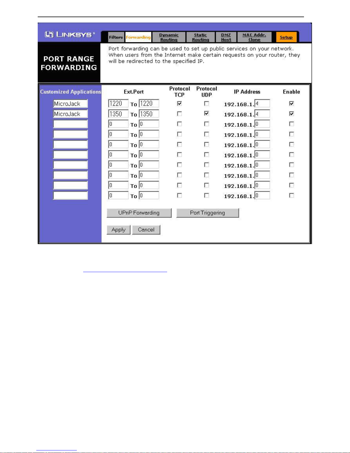
Step 3.3 Click on the "Advanced" tab at the top and then the "Forwarding" tab.
Step 3.4 Enter port 1220 Protocol TCP & port 1350 Protocol UDP. (In my previous step,
I had set my IP address to 192.168.1.4)
- 32 -
MicroJack Part II DVR 4CH/8CH/16CH User’s Manual
Step 3.5 Go to: http://192.168.1.1/Filters.htm and Disable "Block Wan Request"
- 33 -

Appendix A: Network Setup
- 34 -

MicroJack Part II DVR 4CH/8CH/16CH User’s Manual
Router
IP: 61.221.65.58
TCP 1220 192.168.1.4
UDP 1350 192.168.1.4
MicroJack PART II
IP: 192.168.1.4
Gateway: 192.168.1.1
Local Computer #1
IP: 192.168.1.101
Gateway: 192.168.1.1
Sub Mask:255.255.255.0
Local Computer #2
IP: 192.168.1.102
Gateway: 192.168.1.1
Sub Mask:255.255.255.0
Local Computer #3
IP: 192.168.1.103
Gateway: 192.168.1.1
Sub Mask:255.255.255.0
Internet
Computer with Internet service
Remote software connect to
IP: 61.221.65.58
Local Computer #4
IP: 192.168.1.104
Gateway: 192.168.1.1
Sub Mask:255.255.255.0
- 35 -

Appendix A: Network Setup
Other network setting information
ADSL/Cable Modem PART II
You need to have static IP Internet service from your local Internet Service provider.
Just get the IP setting information from your Internet provider and enter it into the DVR Internet settings
(IP address / Gateway / Sub Mask). Then your DVR is ready to support the network function.
MicroJack DEMO site setting:
ADSL / Cable MODEM
MicroJack PART II
IP: 61.221.65.58
Gateway: 61.221.65.50
SubMask:255.255.254.0
- 36 -

MicroJack Part II DVR 4CH/8CH/16CH User’s Manual
Local HUB PART II
This setting only can let you use the remote feature on your local area network.
The IP Address you set must be unique for each computer in your local network.
HUB
MicroJack PART II
IP: 192.168.1.4
Gateway: 192.168.1.1
Sub Mask:255.255.255.0
Local Computer #1
IP: 192.168.1.101
Gateway: 192.168.1.1
Sub Mask:255.255.255.0
Local Computer #2
IP: 192.168.1.102
Gateway: 192.168.1.1
Sub Mask:255.255.255.0
Local Computer #3
IP: 192.168.1.103
Gateway: 192.168.1.1
Sub Mask:255.255.255.0
Local Computer #4
IP: 192.168.1.104
Gateway: 192.168.1.1
Sub Mask:255.255.255.0
- 37 -

Appendix A: Network Setup
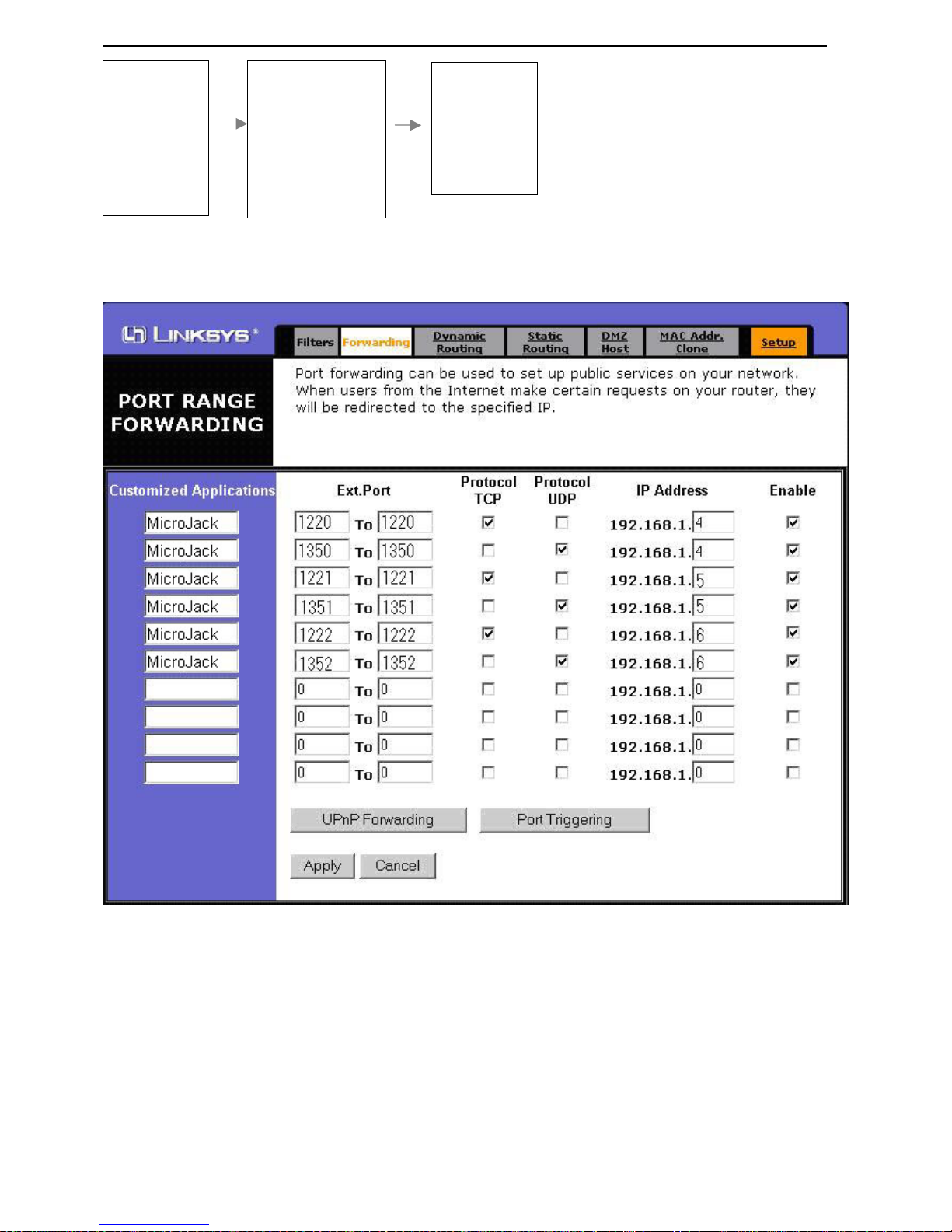
Multi-DVR work with a IP
Router
WAN IP: 61.221.65.58
Local IP: 192.168.1.1
TCP 1220 192.168.1.4
UDP 1350 192.168.1.4
TCP 1221 192.168.1.5
UDP 1351 192.168.1.5
TCP 1222 192.168.1.6
UDP 1352 192.168.1.6
Computer with Internet service
Remote software connect to
P A RT II #1 IP:
61.221.65.58:1220
P A RT II #2 IP:
61.221.65.58:1221
P A RT II #3 IP:
61.221.65.58:1222
PART II
IP: 192.168.1.6
Gateway: 192.168.1.1
Sub Mask:255.255.255.0
TCP: 1222
UDP: 1352
PART II
IP: 192.168.1.5
Gateway: 192.168.1.1
Sub Mask:255.255.255.0
TCP: 1221
UDP: 1351
PART II
IP: 192.168.1.4
Gateway: 192.168.1.1
Sub Mask:255.255.255.0
TCP: 1220
UDP: 1350
Internet
The PORT number can be changed by PART II OSD
Go to your PART II network setting MAIN (OSD) Internet Port IP
- 38 -
MicroJack Part II DVR 4CH/8CH/16CH User’s Manual
Port IP
TCP :1220
UDP :1350
Default
Exit
Password
Channel 1
Channel 2
Channel 3
Channel 4
Date/Time
Display/Record
Others
Alarm Log
Internet
Exit
Username: user
Password: 99999999
Port IP
IP Address:
192.168.001.004
Gateway:
192.168.001.001
Sub mask
255.255.255.000
Exit
Different IP Gateway or IP sharing devices have different setup screens (But the idea is the
same), this example is for LINKSYS only.
Here is example for Multi-DVR PORT setting in LINKSYS router.
- 39 -

Appendix B: PTZ Camera Controller Setup
Appendix B: PTZ Camera Controller Setup
- 40 -

MicroJack Part II DVR 4CH/8CH/16CH User’s Manual
Appendix C: DDNS Solution
DDNS stands for Dynamic Domain Name Service; it is a simple way to attach a static host
name to a dynamic IP address. It also simplifies your IP addresses into easy-to-remember and
meaningful domain names.
MicroJack Part II DVR does not have DDNS function built in at this moment. However, we can
find other solutions to fulfill our users’ need for DDNS.
Solution 1: PC acts as IP-reporter in the same LAN as the DVR.
Most of the DDNS run IP-report programs to signal the DDNS server about the IP changes.
Since MicroJack Part II DVR runs in a real-time embedded OS, which is different from the
ordinary OS like Windows, these IP-report programs cannot be installed on the DVR. If the DVR
is running within a LAN (local area network) and there are other computers within the same
LAN as well, one of the other computers can act as the IP-reporter. Then we can apply port
forwarding to allow the router to direct the traffic to the DVR. In this way we can use DDNS to
access the DVR.
Demonstration Diagram (IP address or DDNS address that appear in this diagram may vary due
to different scenarios)
Router
WAN IP: 66.146.128.196
LAN IP: 192.168.0.1
Port Forwarding: 192.168.0.1 11
TCP: 1220 UDP: 13501
IP Reporter Computer
IP: 192.168.0.110
Gateway: 192.168.0.1
Sub Mask: 255.255.255.0
DDNS: part2.123dss.com
PART II
IP: 192.168.0.111
Gateway: 192.168.0.1
Sub Mask: 255.255.255.0
TCP: 1220 UDP: 13501.1
- 41 -

Appendix C: DDNS Solution
Step1: Obtain your DDNS from a DDNS provider. (E.g. www.123dss.com)
Step2: Set up the DDNS reporter program in one of the computers within the same network as
the DVR, this computer is going to act as the IP reporter.
Step3: Set up the Network information in the DVR (Please refer to Step1 and 2 in the Appendix
A Network Setup Example1)
Step4: Use Port Forwarding to direct the traffic from the router to the DVR. (Please refer to
Step3 in the Network Setup Example1)
Solution 2: Use the DDNS function inside the router and connect the DVR to this router.
A lot of routers have the DDNS function built in. Customers can choose to use this
function instead of using an IP-reporter computer solution. This solution uses less
resources but it requires more network knowledge to set up.
Demonstration Diagram (IP address or DDNS address appearing in this diagram may vary due to
different scenario)
Router
WAN IP: 66.146.128.196
LAN IP: 192.168.0.1
Port Forwarding: 192.168.0.1 11
TCP: 1220 UDP: 13501
PART II
IP: 192.168.0.111
Gateway: 192.168.0.1
Sub Mask: 255.255.255.0
TCP: 1220 UDP: 13501.1
- 42 -

MicroJack Part II DVR 4CH/8CH/16CH User’s Manual
Step1: Purchase a router with DDNS function built in or check your current router to see
whether it supports DDNS function. (We have tested the D-Link DI-604 router and this can
support the DDNS function)
Step2: Obtain DDNS that your router can support from a DDNS provider. (For our tested router
D-Link DI-604, we found the DDNS from www.dyndns.com is comp atible with the D-Link DI-604
router)
Step3: Set up the network for both the router and the DVR (please refer to Appendix A
Example1)
Step4: Set up DDNS function in the router setting (please refer to D-Link and www.dyndns.com
online FAQ or how to set up DDNS parameters.)
- 43 -
 Loading...