

MODELS: UT CT ST
Station mode instructions
For Office furniture, storage cabinets, lockers, safes, vaults, secured enclosures
Getting Started
Two operating modes:
1. Station mode (repeated use with the same code)
2. Locker mode (use with a temporary code)
The operating mode is specified at the time of order. To determine which operating mode the lock is in, remove the battery, press and
release the program button, and reinsert the battery. Note the color sequence of the LED flashes when the battery is reinserted:
☼ (green, red, yellow) indicates station mode
☼ (green, yellow, red) indicates locker mode
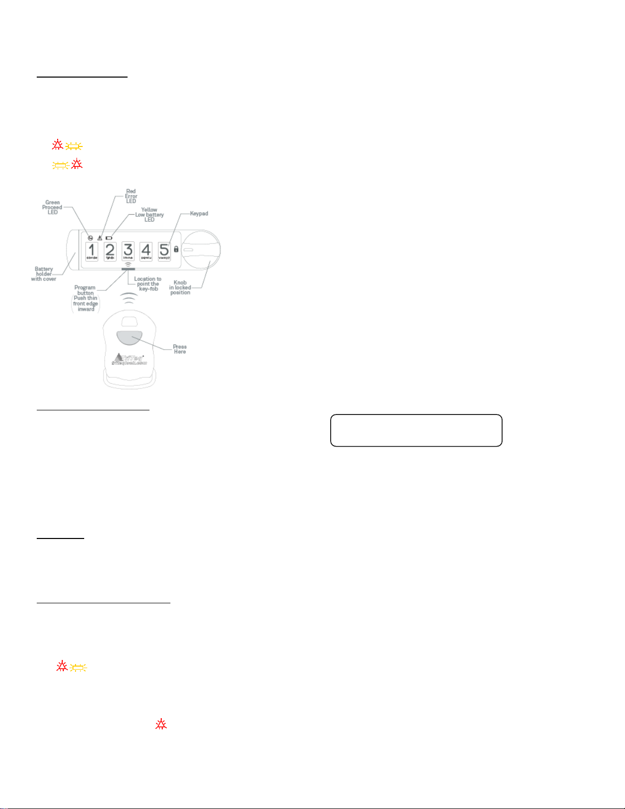
Program button:
Initiate the lock programming mode by pressing the front thin edge of the black button
inward toward the mounting surface the Micro IQ is mounted to.
Infrared Receiver:
The Infrared Receiver will receive a signal from an electronic TriTeq key fob when it is
pointed at the receiver located behind the Program button. The Program button is
slightly opaque so the key-fob signal will penetrate the button.
Knob:
To move the lock mechanism 90 or 180 degrees clockwise or counterclockwise from
the locked and unlocked states.
Multiple levels of access:
1.Master code and/or blue control key fob The factory master code is: 135243
2.Supervisor code and/or black key fob The factory supervisor code is: 123
3.User code and/or black key fob
Note: The MicroIQ is pre-programmed with a factory master code and a factory supervisor code.
Operation:
Unlock with a code by entering a valid code. The green LED will illuminate. Turn the knob to unlock.
To lock, turn the knob to align the knob pointer with the lock icon on the keypad.
Programming Chart Symbols:
P = press program button
●▲■ - Solid color indicates LED is lit
☼ - Indicates LED is flashing
(Nx) – indicates flashes N times
1,2,3,4,5 = Indicates the button number to press
Note: If any there are any errors in executing the steps below or too much time
elapses between the steps, (3x) and the lock will exit the programming mode.

Station Mode Programming Instructions
CHANGE THE MASTER CODE (6 DIGITS) USING THE FACTORY MASTER CODE
CHANGE THE SUPERVISOR CODE (3-6 DIGITS) USING THE FACTORY SUPERVISOR CODE
ADD A USER CODE (3-6 DIGITS) USING THE SUPERVISOR CODE
CHANGE THE MASTER CODE (6 DIGITS)
CHANGE THE SUPERVISOR CODE(3-6 DIGITS) USING A SUPERVISOR CODE
CHANGE THE SUPERVISOR CODE (3-6 DIGITS) USING THE MASTER CODE
P P P P P ● factory master code ●▲ factory master code ▲●■ new master code(2x) ☼ (6x)
Example: P P P P P ● 135243 ●▲ 135243 ▲●■ 112233 (2x) ☼ (6x)
Result: Factory master code 135243 was erased and the new master code 112233 was accepted.
P ● factory supervisor code ▲ new supervisor code P ☼ (6x)
Example: P ● 123 ▲ 4321 P ☼ (6x)
Result: Supervisor code 123 was erased and supervisor code 4321 was added.
P P ▲ supervisor code ■ user code P ☼ (6x)
Example: P P ▲ 4321 ■ 54321 P ☼ (6x)
Result: Supervisor code 4321 was used to add user code 54321.
P P P P P ● old master code ●▲ old master code ▲●■ new master code(2x) ☼ (6x)
Example: P P P P P ● 112233 ●▲ 112233 ▲●■ 123455 123455 ☼ (6x)
Result: Old master code 112233 was erased and new master code 123455 was accepted.
P ● old supervisor code ▲ new supervisor code P ☼(6x)
Example: P ● 4321 ▲ 111555 P ☼(6x)
Result: Supervisor code 4321 was erased and supervisor code 111555 was added.
P ● master code ▲ new supervisor code P ☼ (6x)
Example: P ● 123455 ▲ 531 P ☼ (6x)
Result: Master code 123455 was used to change the supervisor code to 531.

REMOVE THE USER CODE USING THE SUPERVISOR CODE
P P ▲ supervisor code ■ 1 1 1 1 1 P ☼(6x)
ADD A CONTROL FOB
ADD A SUPERVISOR CODE (3-6 DIGITS) USING THE CONTROL FOB
ADD A SUPERVISOR FOB USING THE MASTER CODE
ADD A SUPERVISOR FOB USING THE CONTROL FOB
ADD A USER FOB USING THE SUPERVISOR CODE
Example: P P ▲ 531 ■ 1 1 1 1 1 P ☼(6x)
Result: Supervisor code 531 was used to remove the user code. User code is no longer valid for access.
P ● master code ▲ point control
Example: P ● 123455 ▲ point control fob
Result: Master code 123455 was used to add a control fob.
at P and press fob button
P ● point control fob
Example: P ● point control fob
Result: Control fob was used to add new supervisor code 543.
at P and press fob button ▲ supervisor code P ☼ (6x)
at P and press fob button ▲ 543 P ☼ (6x)
P ● master code ▲ point supervisor fob
Example: P ● 123455 ▲ point supervisor fob
Result: Master code 123455 was used to add a supervisor fob.
at P and press fob button ☼ (6x)
at P and press fob button ☼ (6x)
button ☼(6x) fob at P and press fob
☼(6x)
P ● point control fob at P and press fob button ▲ point supervisor fob
button ☼ (6x)
P P ▲ supervisor code ■ point the user fob
Example: P P ▲ 543 ■ point the user fob
Result: Supervisor code 543 was used to add a user fob.
at P and press fob button ☼ (6x)
at P and press fob button ☼ (6x)
at P and press fob

ADD A USER FOB USING THE SUPERVISOR FOB
REMOVE THE USER FOB USING THE SUPERVISOR CODE
REMOVE THE USER FOB USING THE SUPERVISOR FOB
TO UNLOCK WITH A FOB
at P and press fob button ■ point the user fob P P ▲ point supervisor fob
fob button ☼ (6x)
Result: Supervisor fob was used to add a user fob.
at P and press
P P ▲ supervisor code ■ 1 1 1 1 1 P ☼ (6x)
Example: P P ▲ 543 ■ 1 1 1 1 1 P ☼ (6x)
Result: Supervisor code 543 was used to remove the user fob. User fob is no longer valid for access.
at P and press fob button
Result: User fob is no longer valid for access.
■ 1 1 1 1 1 P ☼ (6x) P P ▲ point supervisor fob
Point a valid fob
Result: The lock will unlock.
at P and press fob button ● turn knob to unlock the lock
Double digit codes:
The numbers 6, 7, 8, and 9 can be entered by pressing two keys simultaneously in order to produce a
sum. For example 2 and 4 can be pressed simultaneously to produce the number 6 (2+4=6). Note, if
the code was programmed using 2+4 as the 6 digit, the 2+4 must be used when accessing the lock,
because other combinations that equal six such as 1+5 are distinguished from 2+4.

Switching Modes
Note: The master code is retained when switching modes.
1. Unlock the MicroIQ and turn the knob to the unlocked position
2. Remove the battery for 10 seconds
3. While holding the program button P, reinsert the battery and wait until all 3 LED’s ●▲■
fade in and fade out simultaneously
4. Release the program button
5. Enter the 6 digit master code. When the master code is entered correctly, the yellow LED will
illuminate.
6. Press button number 1 for station mode, Press button number 2 for locker mode.
7. Once the lock switches modes, the LED’s will flash in a certain order according to the mode
selected.
a. Station Mode: ●▲■
b. Locker Mode: ●■▲
8. Proceed to operate the lock in the selected mode
To watch the programming videos for the station mode please visit http://microiqlock.com/station_mode
For the locker mode video instructions please visit http://microiqlock.com/locker_mode
 Loading...