

Page 1

Operating Manual
pX2
1W OEM 802.11b/g/n Ethernet/Serial WIFI Router
Document: pX2 Operating Manual.v1.1.2.pdf
FW: v1.3.0 Build 1012
January 2016
150 Country Hills Landing NW
Calgary, Alberta
Canada T3K 5P3
Phone: (403) 248-0028
Fax: (403) 248-2762
www.microhardcorp.com
Page 2

Important User Information
Warranty
Microhard Systems Inc. warrants that each product will be free of defects in material and workmanship for a
period of one (1) year for its products. The warranty commences on the date the product is shipped by Micro-
hard Systems Inc. Microhard Systems Inc.’s sole liability and responsibility under this warranty is to repair or
replace any product which is returned to it by the Buyer and which Microhard Systems Inc. determines does
not conform to the warranty. Product returned to Microhard Systems Inc. for warranty service will be shipped
to Microhard Systems Inc. at Buyer’s expense and will be returned to Buyer at Microhard Systems Inc.’s ex-
pense. In no event shall Microhard Systems Inc. be responsible under this warranty for any defect which is
caused by negligence, misuse or mistreatment of a product or for any unit which has been altered or modified
in any way. The warranty of replacement shall terminate with the warranty of the product.
Warranty Disclaims
Microhard Systems Inc. makes no warranties of any nature of kind, expressed or implied, with respect to the
hardware, software, and/or products and hereby disclaims any and all such warranties, including but not limited to warranty of non-infringement, implied warranties of merchantability for a particular purpose, any interruption or loss of the hardware, software, and/or product, any delay in providing the hardware, software, and/
or product or correcting any defect in the hardware, software, and/or product, or any other warranty. The Purchaser represents and warrants that Microhard Systems Inc. has not made any such warranties to the Purchaser or its agents MICROHARD SYSTEMS INC. EXPRESS WARRANTY TO BUYER CONSTITUTES MICROHARD
SYSTEMS INC. SOLE LIABILITY AND THE BUYER’S SOLE REMEDIES. EXCEPT AS THUS PROVIDED, MICROHARD
SYSTEMS INC. DISCLAIMS ALL WARRANTIES, EXPRESS OR IMPLIED, INCLUDING ANY WARRANTY OF MERCHANTABILITY OR FITNESS FOR A PARTICULAR PROMISE.
MICROHARD SYSTEMS INC. PRODUCTS ARE NOT DESIGNED OR INTENDED TO BE USED IN
ANY LIFE SUPPORT RELATED DEVICE OR SYSTEM RELATED FUNCTIONS NOR AS PART OF
ANY OTHER CRITICAL SYSTEM AND ARE GRANTED NO FUNCTIONAL WARRANTY.
Indemnification
The Purchaser shall indemnify Microhard Systems Inc. and its respective directors, officers, employees, successors and assigns including any subsidiaries, related corporations, or affiliates, shall be released and discharged from any and all manner of action, causes of action, liability, losses, damages, suits, dues, sums of
money, expenses (including legal fees), general damages, special damages, including without limitation,
claims for personal injuries, death or property damage related to the products sold hereunder, costs and demands of every and any kind and nature whatsoever at law.
IN NO EVENT WILL MICROHARD SYSTEMS INC. BE LIABLE FOR ANY INDIRECT, SPECIAL, CONSEQUENTIAL,
INCIDENTAL, BUSINESS INTERRUPTION, CATASTROPHIC, PUNITIVE OR OTHER DAMAGES WHICH MAY BE
CLAIMED TO ARISE IN CONNECTION WITH THE HARDWARE, REGARDLESS OF THE LEGAL THEORY BEHIND
SUCH CLAIMS, WHETHER IN TORT, CONTRACT OR UNDER ANY APPLICABLE STATUTORY OR REGULATORY
LAWS, RULES, REGULATIONS, EXECUTIVE OR ADMINISTRATIVE ORDERS OR DECLARATIONS OR OTHERWISE,
EVEN IF MICROHARD SYSTEMS INC. HAS BEEN ADVISED OR OTHERWISE HAS KNOWLEDGE OF THE POSSIBILITY OF SUCH DAMAGES AND TAKES NO ACTION TO PREVENT OR MINIMIZE SUCH DAMAGES. IN THE EVENT
THAT REGARDLESS OF THE WARRANTY DISCLAIMERS AND HOLD HARMLESS PROVISIONS INCLUDED ABOVE
MICROHARD SYSTEMS INC. IS SOMEHOW HELD LIABLE OR RESPONSIBLE FOR ANY DAMAGE OR INJURY, MICROHARD SYSTEMS INC.'S LIABILITY FOR ANYDAMAGES SHALL NOT EXCEED THE PROFIT REALIZED BY MICROHARD SYSTEMS INC. ON THE SALE OR PROVISION OF THE HARDWARE TO THE CUSTOMER.
Proprietary Rights
The Buyer hereby acknowledges that Microhard Systems Inc. has a proprietary interest and intellectual property rights in the Hardware, Software and/or Products. The Purchaser shall not (i) remove any copyright, trade
secret, trademark or other evidence of Microhard Systems Inc.’s ownership or proprietary interest or confiden-
tiality other proprietary notices contained on, or in, the Hardware, Software or Products, (ii) reproduce or modify any Hardware, Software or Products or make any copies thereof, (iii) reverse assemble, reverse engineer or
decompile any Software or copy thereof in whole or in part, (iv) sell, transfer or otherwise make available to
others the Hardware, Software, or Products or documentation thereof or any copy thereof, except in accordance with this Agreement.
© Microhard Systems Inc. 2
Page 3
Important User Information (continued)
About This Manual
It is assumed that users of the products described herein have either system integration or
design experience, as well as an understanding of the fundamentals of radio communications.
Throughout this manual you will encounter not only illustrations (that further elaborate on the
accompanying text), but also several symbols which you should be attentive to:
Caution or Warning
Usually advises against some action which could result in undesired or
detrimental consequences.
Point to Remember
Highlights a key feature, point, or step which is noteworthy. Keeping
these in mind will simplify or enhance device usage.
Tip
An idea or suggestion to improve efficiency or enhance usefulness.
Information
Information regarding a particular technology or concept.
© Microhard Systems Inc. 3
Page 4

Important User Information (continued)
Regulatory Requirements / Exigences Réglementaires
WARNING:
To satisfy FCC RF exposure requirements for mobile transmitting devices, a separation distance of 23 cm or more should be maintained between
the antenna of this device and persons during device operation. To ensure compliance, operations at closer than this distance is not recommended.
The antenna used for this transmitter must not be co-located in conjunction with any other antenna or transmitter.
WARNING:
Operation is subject to the following two conditions: (1) this device may not cause harmful interference, and (2) this device must accept any
interference received including interference that may cause undesired operation.
WARNING:
Changes or modifications not expressly approved by Microhard Systems Inc. could void the user’s authority to operate the equipment. This device
has been tested with UFL to Reverse Polarity SMA connectors with the antennas listed in Appendix A When integrated in OEM products, fixed
antennas require installation preventing end-users from replacing them with non-approved antennas. Antennas not listed in the tables must be
tested to comply with FCC Section 15.203 (unique antenna connectors) and Section 15.247 (emissions).
WARNING:
MAXIMUM EIRP
FCC Regulations allow up to 36 dBm equivalent isotropically radiated power (EIRP). Therefore, the sum of the transmitted power (in dBm), the
cabling loss and the antenna gain cannot exceed 36 dBm.
WARNING:
EQUIPMENT LABELING
The FCC and IC numbers depend on the model of the radio module. Do NOT use the Marketing Name of the product but the Model to distinguish
the Certifications Numbers. This device has been modularly approved. The manufacturer, product name, and FCC and Industry Canada
identifiers of this product must appear on the outside label of the end-user equipment.
WARNING:
This device complies with Industry Canada’s license-exempt RSSs. Operation is subject to the following two conditions:
(1) This device may not cause interference; and (2) This device must accept any interference, including interference that may cause undesired
operation of the device.
SAMPLE LABEL REQUIREMENT / EXIGENCE D'ÉTIQUETTE: px2
FCCID: NS915PX2
IC: 3143A-15PX2
This device complies with Part 15 of the FCC Rules.
Operation is subject to the following two conditions:
(1) this device may not cause harmful interference,
and (2) this device must accept any interference
received including interference that may cause
undesired operation.
Please Note: These are only sample labels; different products contain different identifiers. The actual identifiers should be seen on
your devices if applicable. S'il vous plaît noter: Ce sont des exemples d'étiquettes seulement; différents produits contiennent des
identifiants différents. Les identifiants réels devrait être vu sur vos périphériques le cas échéant.
© Microhard Systems Inc. 4
Page 5
Important User Information (continued)
Regulatory Requirements / Exigences Réglementaires
WARNING:
Pour satisfaire aux exigences de la FCC d'exposition RF pour la base et mobiles sur une distance de séparation de 23 cm ou plus doit être
maintenue entre l'antenne de cet appareil et des personnes lors de fonctionnement du dispositif. Pour assurer la conformité d es opérations au
plus près que cette distance n'est pas recommandée. L'antenne utilisée pour ce transmetteur ne doit pas être co-localisés en conjonction avec
toute autre antenne ou transmetteur.
WARNING:
Son fonctionnement est soumis aux deux conditions suivantes : ( 1 ) ce dispositif ne doit pas causer d'interférences nuisibles et ( 2) cet appareil
doit accepter toute interférence reçue, incluant les interférences qui peuvent provoquer un fonctionnement indésirable .
WARNING:
Les changements ou modifications non expressément approuvés par Microhard Systems Inc. pourraient annuler l'autorité de l'utilisateur à utiliser
l'équipement . Ce dispositif a été testé avec MCX et connecteurs SMA à polarité inverse sur les antennes répertoriées à l'annexe A Lorsqu'il est
intégré dans les produits OEM , antennes fixes nécessitent une installation empêchant les utilisateurs finaux de les remplacer par des antennes non
approuvées . Antennes ne figurant pas dans les tableaux doivent être testés pour se conformer à la Section 15.203 (connecteurs d'antenne
uniques ) et à la Section 15.247 ( émissions ) .
WARNING:
MAXIMUM PIRE
Règlement FCC permettent jusqu'à 36 dBm puissance isotrope rayonnée équivalente ( PIRE) . Par conséquent, la somme de la puissance émise ( en
dBm ), la perte de câblage et le gain d'antenne ne peut pas dépasser 36 dBm.
WARNING:
ÉQUIPEMENT DE MARQUAGE
Les numéros FCC et IC dépendent du modèle du module radio . Ne pas utiliser le nom marketing du produit, mais le modèle de distinguer les
numéros Certifications . Ce dispositif a été approuvé de façon modulaire . Le fabricant , nom du produit, et les identificateurs de la FCC et
d'Industrie Canada de ce produit doivent figurer sur l'étiquette à l'extérieur de l'équipement de l'utilisateur final .
WARNING:
Cet appareil est conforme aux CNR exempts de licence d'Industrie Canada . Son fonctionnement est soumis aux deux conditions suivantes : ( 1 ) Ce
dispositif ne peut causer des interférences ; et ( 2 ) Ce dispositif doit accepter toute interférence , y compris les interférences qui peuvent causer un
mauvais fonctionnement de l'appareil.
SAMPLE LABEL REQUIREMENT / EXIGENCE D'ÉTIQUETTE: px2
FCCID: NS915PX2
IC: 3143A-15PX2
This device complies with Part 15 of the FCC Rules.
Operation is subject to the following two conditions:
(1) this device may not cause harmful interference,
and (2) this device must accept any interference
received including interference that may cause
undesired operation.
Please Note: These are only sample labels; different products contain different identifiers. The actual identifiers should be seen on
your devices if applicable. S'il vous plaît noter: Ce sont des exemples d'étiquettes seulement; différents produits contiennent des
identifiants différents. Les identifiants réels devrait être vu sur vos périphériques le cas échéant.
© Microhard Systems Inc. 5
Page 6

Important User Information (continued)
Regulatory Requirements / Exigences Réglementaires
Co-Location with Cellular Modems
The maximum calculated MPE ratio for the EUT with 2 dBi dipole antenna is 0.238, this configuration can be co-located with
other antennas provided the sum of the MPE ratios for all the other simultaneous transmitting antennas incorporated in a
host device is < 1.0 - 0.238 < 0.762. The following co-location were evaluated for mobile configurations:
1. EUT with 2 dBi dipole antenna co-located with Data Card Module (FCC ID RI7LN930, IC: 5131A-LN930)
2. EUT with 2 dBi dipole antenna co- located with LTE Data Transmitter Module (FCC ID R5Q-TOBYL100, IC
8595B-TOBYL100)
3. EUT with 2 dBi dipole antenna co- located with GSM/UMTS/LTE Data Module (FCC ID XPYTOBYL200, IC
Co - localisation avec Cellular Modem
Le maximum calculé rapport EMT pour l'EST avec antenne dipôle 2 dBi est de 0,238 , cette configuration peut être cosituée avec d'autres antennes à condition que la somme des rapports MPE pour tous les autres antennes de transmission
simultanées incorporés dans un dispositif hôte est < 1,0 à 0,238 < 0,762 . Le co- emplacement suivant ont été évalués pour
les configurations mobiles :
8595A-TOBYL200)
1. EUT avec 2 dBi antenne dipôle co-localisé avec module de carte de données ( FCC ID RI7LN930 , IC : 5131A
- LN930)
2. EUT avec 2 dBi antenne dipôle co- localisé avec LTE données Module émetteur ( FCC ID R5QTOBYL100 , IC
8595B - TOBYL100 )
3. EUT avec 2 dBi antenne dipôle situé coopération avec les réseaux GSM / UMTS / LTE du module de données
( FCC ID XPYTOBYL200 , IC - 8595A TOBYL200 )
© Microhard Systems Inc. 6
Page 7

Revision History
Revision Description Initials Date
0.0 Preliminary Release. Based on Firmware v1.0.0 Build 1003 PEH July 2015
0.1 Added pX2 Development Board PEH Sept 2015
0.2 Added/Updated AT Commands as of firmware v1.3.0-r1007-13 PEH Sept 2015
0.3 Updated Network Section PEH Oct 2015
0.31 AT Command Corrections PEH Oct 2015
1.0 Updated to firmware 1.3.0 Build 1010 PEH Dec 2015
1.1 Updated Network > WAN, Firewall > Port forwarding Firewall >
Rules. Updated AT Commands.
1.1.1 Updated to firmware 1.3.0 Build 1011-60 PEH Jan 2016
1.1.2 Updated to firmware 1.3.0 Build 1012 PEH Jan 2016
PEH Dec 2015
© Microhard Systems Inc. 7
Page 8

Table of Contents
1.0 Overview ......................................................................................................... 11
1.1 Performance Features ................................................................................................... 11
1.2 Specifications ................................................................................................................ 12
1.3 pX2 Performance .......................................................................................................... 13
2.0 QUICK START ................................................................................................. 14
2.1 Getting Started .............................................................................................................. 12
2.2 Simple Access Point and Client ..................................................................................... 16
2.2.1 Configuring the Access Point (AP) ....................................................................... 16
2.2.2 Configuring the Client/Station .............................................................................. 18
2.2.3 Testing the Connection ........................................................................................ 20
3.0 Hardware Features ......................................................................................... 21
3.1 pX2 ............................................................................................................................... 21
3.1.1 pX2 Mechanical Drawings .................................................................................... 22
3.1.2 Recommended Solder Mask (Pad Landing) ......................................................... 23
3.1.3 Recommended Solder Paste Pattern ................................................................... 24
3.1.4 OEM Connectors ................................................................................................. 24
3.1.5 OEM Pin Descriptions .......................................................................................... 25
3.2 pX2 Development Board ............................................................................................... 28
3.2.1 Connectors & Indicators ....................................................................................... 29
4.0 Configuration.................................................................................................. 31
4.0 Web User Interface ...................................................................................................... 31
4.0.1 Logon Window ..................................................................................................... 32
4.1 System ......................................................................................................................... 33
4.1.1 Summary ............................................................................................................. 33
4.1.2 Settings ............................................................................................................... 34
Host Name .......................................................................................................... 34
Console Timeout.................................................................................................. 34
Date/Time ............................................................................................................ 35
NTP Server Settings ............................................................................................ 36
4.1.3 Services .............................................................................................................. 37
SSH ..................................................................................................................... 37
Telnet .................................................................................................................. 37
HTTP/HTTPS ...................................................................................................... 37
4.1.4 Maintenance ........................................................................................................ 38
Firmware Upgrade ............................................................................................... 38
Backup & Restore Configurations ........................................................................ 39
4.1.5 Reboot ................................................................................................................. 40
4.2 Network ....................................................................................................................... 41
4.2.1 Status .................................................................................................................. 41
4.2.2 LAN ..................................................................................................................... 42
LAN DHCP .......................................................................................................... 44
MAC Binding........................................................................................................ 46
4.2.3 WAN .................................................................................................................... 47
4.2.4 Ports .................................................................................................................... 49
4.2.5 Device List ........................................................................................................... 50
© Microhard Systems Inc. 8
Page 9

Table of Contents
4.3 Wireless ....................................................................................................................... 51
4.3.1 Status .................................................................................................................. 51
4.3.2 Radio1 ................................................................................................................. 52
Radio1 PHY Configuration ................................................................................... 52
Radio Mode ......................................................................................................... 52
Radio Channel (Frequency) ................................................................................. 53
Wireless TX Power .............................................................................................. 53
Radio1 Virtual Interface........................................................................................ 55
Operating Mode ................................................................................................... 55
Wireless SSID ..................................................................................................... 57
4.4 Firewall ....................................................................................................................... 59
4.4.1 Summary ............................................................................................................. 59
4.4.2 General ............................................................................................................... 60
4.4.3 Port Forwarding ................................................................................................... 62
4.4.4 MAC-IP List ......................................................................................................... 64
4.4.5 Rules ................................................................................................................... 66
4.4.4 Default ................................................................................................................. 68
4.5 Serial ............................................................................................................................ 69
4.5.1 Summary ............................................................................................................. 69
4.5.2 RS232 Port Settings ............................................................................................ 70
Data Baud Rate ................................................................................................... 71
IP Protocol Config ................................................................................................ 73
TCP Client/Server ........................................................................................... 74
UDP Point-to-Point .......................................................................................... 74
SMTP Client .................................................................................................... 74
PPP ................................................................................................................ 75
4.6 Apps ............................................................................................................................ 76
4.6.1 Event Report ...................................................................................................... 76
4.6.1.1 Configuration ....................................................................................... 76
4.6.1.2 Message Structure ............................................................................... 77
4.6.1.3 Message Payload................................................................................. 78
4.7 Diag .............................................................................................................................. 79
4.7.1 Ping ................................................................................................................... 79
4.7.2 Traceroute ......................................................................................................... 79
4.7.3 Iperf ................................................................................................................... 80
4.8 Admin .......................................................................................................................... 81
4.8.1 Users ................................................................................................................. 81
4.8.2 Authentication (RADIUS) .................................................................................... 83
4.8.3 NMS .................................................................................................................. 84
4.8.4 SNMP ................................................................................................................ 88
4.8.5 Discovery ........................................................................................................... 91
4.8.6 Logout ................................................................................................................ 92
© Microhard Systems Inc. 9
Page 10

Table of Contents
5.0 AT Command Line Interface........................................................................... 93
5.1 AT Command Overview .............................................................................................. 93
5.1.1 Telnet (TCP/IP) .................................................................................................. 93
5.2 AT Command Syntax .................................................................................................. 94
5.3 Supported AT Commands .......................................................................................... 95
6.0 Installation ....................................................................................................... 131
6.1 Path Calculation .......................................................................................................... 133
6.2 Installation of Antenna System Components ............................................................ 134
6.2.1 Antennas............................................................................................................ 135
6.2.2 Coaxial Cable ..................................................................................................... 135
6.2.3 Surge Arrestors .................................................................................................. 135
6.2.4 External Filter ..................................................................................................... 135
Appendices .......................................................................................................... 136
Appendix A: Serial Interface .................................................................................................. 136
Appendix B: Firmware Recovery ........................................................................................... 137
Appendix C: Approved Antennas ........................................................................................... 138
Appendix D: Sample Interface Schematic .............................................................................. 139
Appendix E: Troubleshooting/FAQ ........................................................................................ 141
© Microhard Systems Inc. 10
Page 11

1.0 Overview
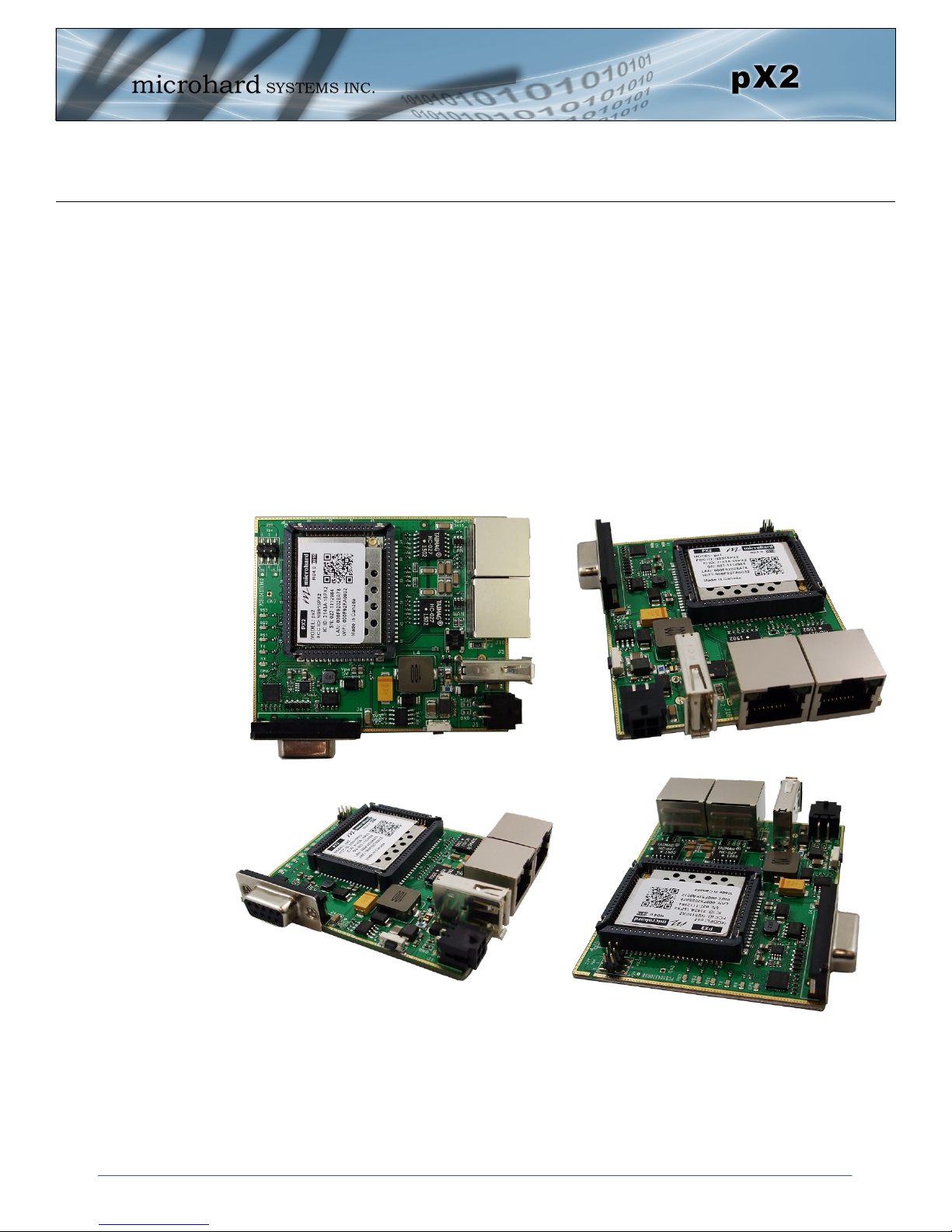
The pX2 is a feature rich, high power, OEM, 802.11 Ethernet/Serial WIFI Router. The pX2 is
designed to provide high performance 802.11b/g/n WIFI capabilities in a compact and rugged
OEM module for system integration. The PX2 features dual 10/100 Ethernet, Serial (RS232)
Gateway and 802.11 WIFI capabilities for wireless applications
The pX2 can be configured using a built-in WebUI interface which does not require any additional software or tools to setup or download. The unit can operate as a Access Point, providing 802.11b/g/n WIFI to wireless devices. It can also operate in Station or Repeater modes to
establish workstations and/or long range wireless links between locations.
Providing reliable wireless Ethernet bridge functionality as well gateway service for most
equipment types which employ an RS232 interface, the pX2 can be used in various types of
applications such as:
High-speed backbone
IP video surveillance
Voice over IP (VoIP)
Ethernet wireless
extension
Mobile Internet
Legacy network/device
migration
SCADA (PLC’s, Modbus,
Hart)
Display Signs
Fleet Services
1.1 Performance Features
Key performance features of the pX2 include:
High Power Tx (up to 1W) w/ Excellent Rx Sensitivity
Up to 150 Mbps data rate
Support for 802.11b/g/n Devices
Firewall with ACL Security, Port Forwarding
Full Scale Access Point, AP Station
Multiple SSID Support
Serial Gateway (RS232)
Dual 10/100 Ethernet Ports
RSSI LED pins for Antenna Alignments
Industrial grade operating temperature (-40oC to +85oC)
Administration via local console, telnet, web browser, SNMP
Local and remote wireless firmware upgradable
© Microhard Systems Inc. 11
Page 12

1.0 Overview
1.2 Specifications
For detailed specifications, please see the specification sheets available on the Microhard website @
http:///www.microhardcorp.com for your specific model.
Electrical/General
Frequency: 2.4000 - 2.4835 GHz
Link Rate: Up to 150 Mbps
Radio Operation 802.11b/g/n
TX Power: 11 dBm - 30 dBm (Selectable)
Channel Bandwidth: 20 or 40 MHz (Selectable)
Error Detection/Control: ARQ/FEC
Data Encryption*: WEP, WPA(PSK), WPA2(PSK), WPA+WPA2 (PSK)
(May require an export permit)
Range: Up to 10 miles (16km) (Antenna Dependant)
Serial Port: 300bps to 921kbps - RS232 (Tx, Rx, RTS, CTS, DTR, DSR)
Ethernet: Dual 10/100 BaseT, Auto - MDI/X, IEEE 802.3
Network Protocols: TCP, UDP, TCP/IP, ARP, ICMP, DHCP, HTTP, HTTPS*, SSH*,
SNMP, FTP, DNS, Serial over IP
(*May require an export permit)
Operating Modes: Access Point, Client/Station, Repeater, Mesh Point
Management: Local Serial Console, Telnet, WebUI, SNMP, FTP &
Wireless Upgrade
Diagnostics: Status LED’s, RSSI, remote diagnostics, SNR, TX/RX CCQ
Input Voltage: Vcc: 3.3 VDC Nominal (+/- 0.3V)
Vrf: 3.3 to 5.0 VDC (5V for 1W output)
Environmental
Operation Temperature: -40oF(-40oC) to 185oF(85oC)
Humidity: 5% to 95% non-condensing
Mechanical
Dimensions: 1.05” (26.5mm) X 1.3” (33mm) X 0.13” (3.5mm)
Weight: Approx. 5 grams
Connectors: Antenna: UFL
Data: 80 Pin SMT
© Microhard Systems Inc. 12
Page 13

1.0 Overview
1.3 Performance Specifications
Rate Mode Tx Power
1 Mbps 802.11b 30 dBm -97 dBm ±1 dB
2 Mbps 802.11b 30 dBm -96 dBm ±1 dB
5.5 Mbps 802.11b 30 dBm -95 dBm ±1 dB
11 Mbps 802.11b 30 dBm -92 dBm ±1 dB
6 Mbps 802.11g 30 dBm -94 dBm ±1 dB
9 Mbps 802.11g 30 dBm -93 dBm ±1 dB
12 Mbps 802.11g 30 dBm -91 dBm ±1 dB
18 Mbps 802.11g 30 dBm -90 dBm ±1 dB
24 Mbps 802.11g 28 dBm -86 dBm ±1 dB
36 Mbps 802.11g 28 dBm -83 dBm ±1 dB
48 Mbps 802.11g 26 dBm -77 dBm ±1 dB
54 Mbps 802.11g 26 dBm -75 dBm ±1 dB
MCS0 802.11n (HT20) 30 dBm -96 dBm ±1 dB
MCS1 802.11n (HT20) 30 dBm -95 dBm ±1 dB
MCS2 802.11n (HT20) 30 dBm -92 dBm ±1 dB
MCS3 802.11n (HT20) 28 dBm -90 dBm ±1 dB
MCS4 802.11n (HT20) 28 dBm -86 dBm ±1 dB
MCS5 802.11n (HT20) 26 dBm -83 dBm ±1 dB
MCS6 802.11n (HT20) 26 dBm -77 dBm ±1 dB
MCS7 802.11n (HT20) 26 dBm -75 dBm ±1 dB
MCS0 802.11n (HT40) 30 dBm -94 dBm ±1 dB
MCS1 802.11n (HT40) 30 dBm -93 dBm ±1 dB
MCS2 802.11n (HT40) 30 dBm -90 dBm ±1 dB
MCS3 802.11n (HT40) 28 dBm -89 dBm ±1 dB
MCS4 802.11n (HT40) 28 dBm -84 dBm ±1 dB
MCS5 802.11n (HT40) 26 dBm -81 dBm ±1 dB
MCS6 802.11n (HT40) 26 dBm -75 dBm ±1 dB
MCS7 802.11n (HT40) 26 dBm -73 dBm ±1 dB
Table 1-1: pX2 Performance Specifications
(Vpa=5V)
Receive
© Microhard Systems Inc. 13
Page 14
2.0 Quick Start
This QUICK START guide will walk you through the setup and configuration of a few
basic applications. The QUICK START will rely on the WebUI for configuration. This
walkthrough also assumes the units used are installed in microhard interface/
development boards or custom boards that allow access to the LAN port. See the
appropriate section for pin-outs.
Note that the units arrive from the factory with a Radio Configuration of ‘Access
Point’ and the Local Network setting configured as ‘Static’ (IP Address
192.168.168.1, Subnet Mask 255.255.255.0). DHCP is enabled by default, and will
assign an IP to a connected device.
2.1 Getting Started
Connect an appropriate Antenna to the ANTENNA connector of the pX2.
Connect and/or apply a suitable power source to the unit.
To reset to factory
defaults, press and
hold the CONFIG for 8
seconds with the pX2
powered up. The pX2
will reboot with factory
default settings.
The factory default
network settings:
IP: 192.168.168.1
Subnet: 255.255.255.0
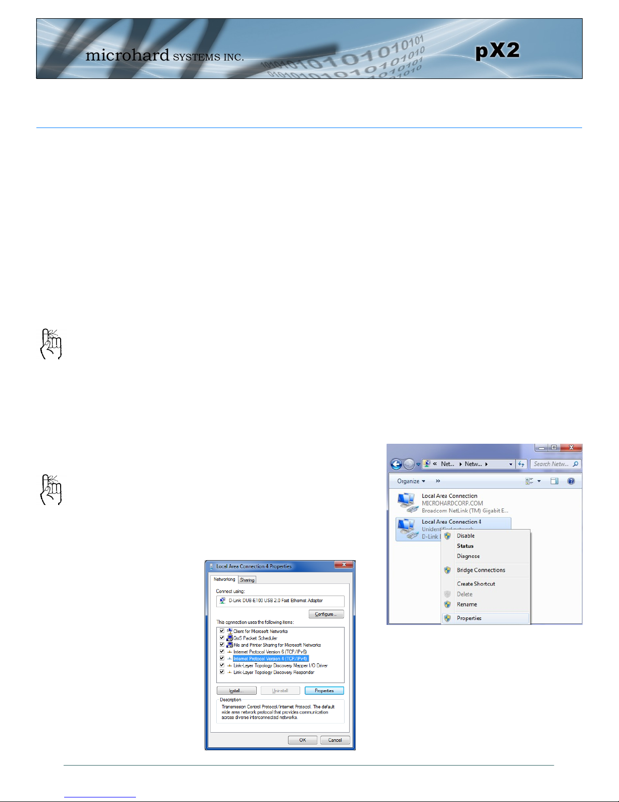
Connect A PC to the LAN port (eth0) of the pX2, using an Ethernet Cable.
The PC must have its Network Setting (TCP/IP Properties) set to DHCP (The mo-
dem will assign a IP address to you), or STATIC with an IP Address of (e.g.)
192.168.168.10 and a Subnet Mask of 255.255.255.0.
To set a Static IP, in Windows 7 the TCP/
IP Properties can be found in:
Start > Search Bar “Network and Sharing
Center”
Select “Change Adapter Settings” on the left
menu, and the right click the Ethernet
adapter connected to the pX2.
© Microhard Systems Inc. 14
Select Internet Protocol (TCP/IPv4)
and then Properties.
Page 15
2.0 Quick Start
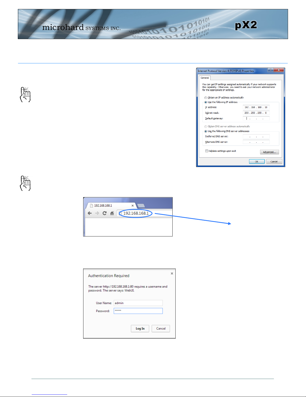
Select Use the following IP address and
enter the values below as shown:
IP Address: 192.168.168.10
Subnet Mask: 255.255.255.0
The factory default
network settings:
IP: 192.168.168.1
Subnet: 255.255.255.0
The factory default login:
User name: admin
Subnet: admin
It is always a good idea to
change the default admin
login for future security.
Click OK
Open a Browser Window and enter the IP address 192.168.168.1 into the ad-
dress bar.
The pX2 will then ask for a Username and Password. Enter the factory defaults
listed below.
Once successfully logged in, the System Summary window will be displayed.
192.168.168.1
The Factory default login:
User name: admin
Password: admin
© Microhard Systems Inc. 15
Page 16
2.0 Quick Start
2.2 Simple Access Point and Station/Client
This Quick Start example requires (2) pX2 modules, one will be configured as a
Access Point (AP), the second unit will be configured as a Station/Client (ST). This
example will show the basic steps required to set up each unit so that a simple network will be established.
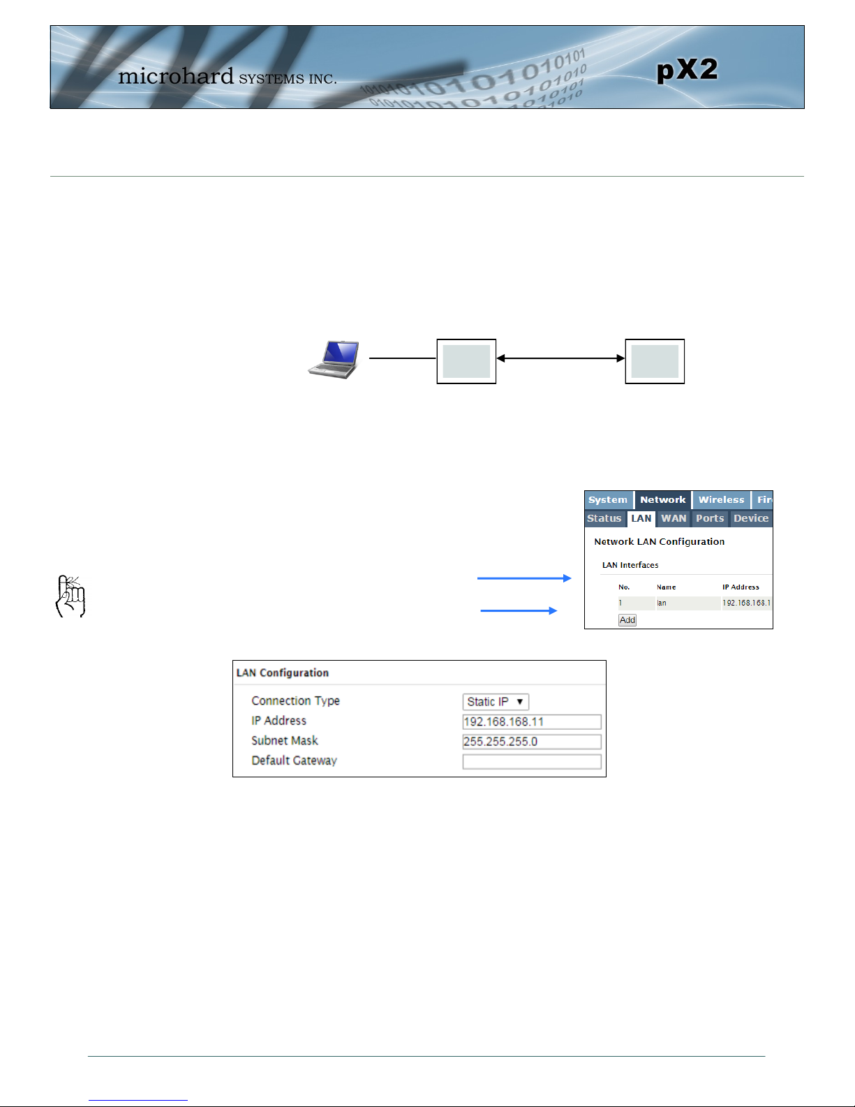
2.2.1 Configuring the Access Point
Use Section 2.1 Getting Started to connect, power up and log in to a pX2 unit.
Give the pX2 unit a unique IP address.
Select Network from the top/main
navigation.
Select LAN from the submenu list,
and then select Edit.
To connect to an
existing network,
contact your Network
Administrator for valid
network settings.
AP ST
Wireless
Choose Static IP for the Connection Type.
Enter the following Network Information:
IP Address: 192.168.168.11
IP Subnet Mask: 255.255.255.0
Click on the Submit button to write the changes to the pX2. The Cancel button will re-
vert back to last values saved to the unit.
Once the IP Address is changed, you will need to type the new address into
your browser to continue the configuration.
© Microhard Systems Inc. 16
Page 17
2.0 Quick Start
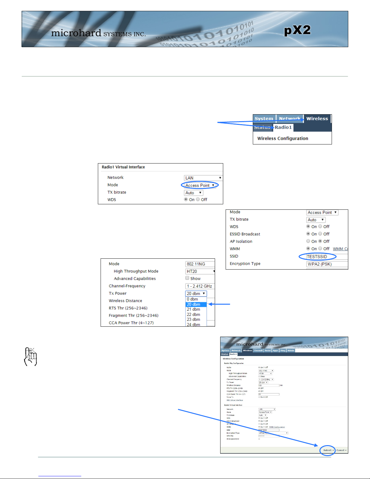
2.2.1 Configuring the Access Point (Con’t)
Configure the pX2 as an Access Point
Select Wireless from the top/main navi-
gation, and then Radio1 from the sub-
menu list.
Enter a unique SSID as shown.
In the Radio1 Virtual Interface section, select Access Point from the
Mode dropdown box.
TESTSSID
For bench or close proximity testing it
is best to use a lower power setting to
prevent RF saturation. Select 20dBm
from the TX Power setting.
The remaining settings in the
Wireless menu should be left as
defaults for this exercise.
If any additional
settings need to be
changed, ensure they
are also changed on
the Station.
© Microhard Systems Inc. 17
Click on the Submit button to
write the changes to the pX2. The
Cancel button will revert back to
previously saved values.
Page 18
2.0 Quick Start
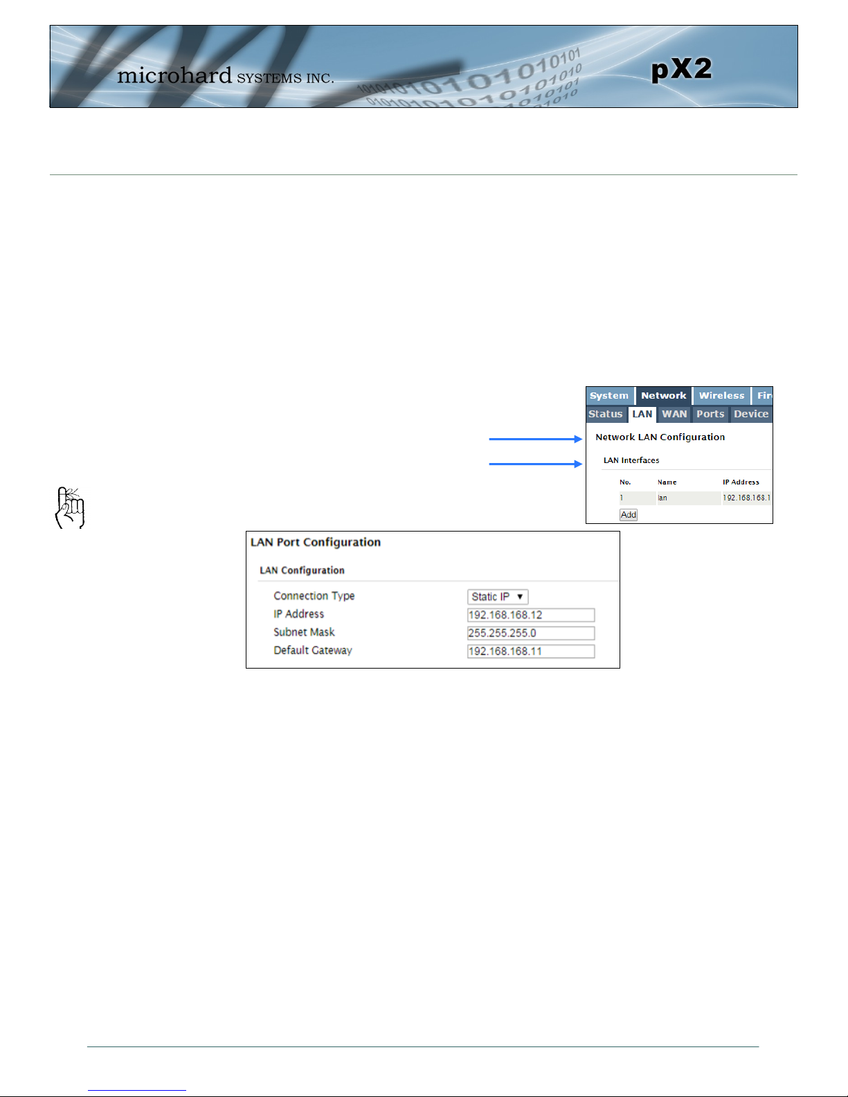
2.2.2 Configuring the Station/Client
The following procedure describes the steps required to set up a pX2 unit as a Station/Client (ST). A Station provides a single wireless connection (i.e to an Access
Point) and provides a wired connection to a PC or other devices.
Use Section 2.1 Getting Started to connect, power up and log in to a second
pX2 unit.
Give the pX2 a unique IP address.
To connect to an
existing network,
contact your Network
Administrator for valid
network settings.
Select Network from the top/main
navigation.
Select LAN from the submenu list,
and then select Edit.
Choose Static IP for the Connection Type.
Enter the following Network Information:
IP Address: 192.168.168.12
IP Subnet Mask: 255.255.255.0
Default Gateway: 192.168.168.11
Click on the Submit button to write the changes to the pX2. The Reset button will
revert back to last values saved to the unit.
Once the IP Address is changed, you will need to type the new address into
your browser to continue the configuration.
© Microhard Systems Inc. 18
Page 19
2.0 Quick Start
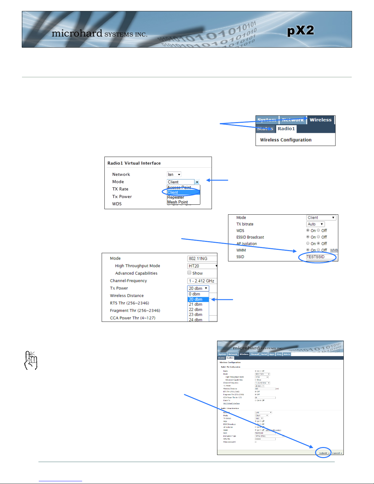
2.2.2 Configuring the Station/Client (Continued)
Configure the pX2 as a Station/Client.
Select Wireless from the top/main navi-
gation, and then Radio1 from the sub-
menu list.
Enter a unique Network Name(SSID)
as shown.
The remaining settings in the
Wireless menu should be left as
defaults for this exercise.
Click on the Submit button to
write the changes to the pX2. The
If any additional
settings need to be
changed, ensure they
are also changed on
the Station.
Cancel button will revert back to
previously saved values
In the Radio1 Virtual Interface section, select Client from the Mode
dropdown box.
TESTSSID
For bench or close proximity testing
it is best to use a lower power setting to prevent RF saturation. Select
20dBm from the TX Power setting.
© Microhard Systems Inc. 19
Page 20
2.0 Quick Start
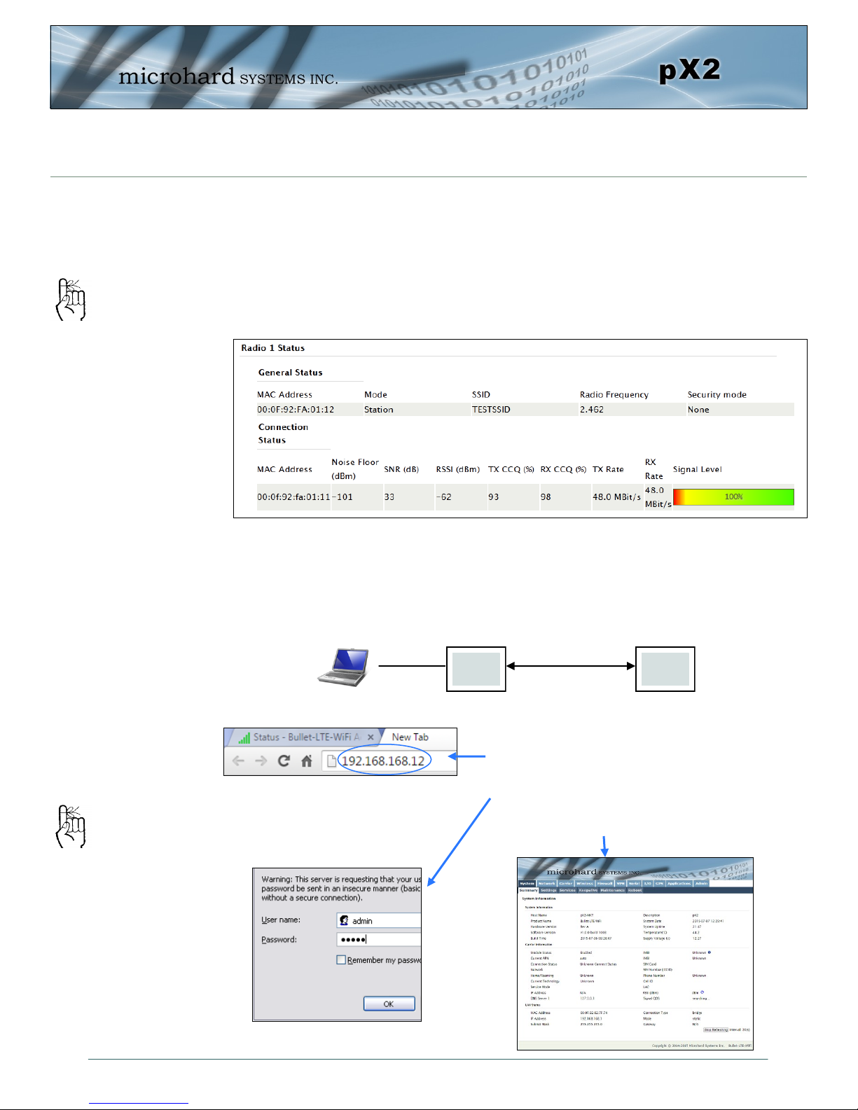
2.2.3 Testing the Connection
Visually check to see if the pX2 units are communicating.
The RSSI LED’s represent signal strength, the more LED’s that are illuminated, the
stronger the signal. The Wireless > Status window also has a Connection Status sec-
tion as seen below:
RSSI LED’s that are
‘cycling’ or ‘scanning’
indicate that the unit
is searching for a
signal.
With the PC connected to the Access Point (AP), type in the IP address of the
Station (ST) into the URL address bar of your browser. You should be able to
connect, log in and view the WebUI of the Station via the wireless connection.
AP ST
Wireless
Open a browser and type in the address of
the station/client: 192.168.168.12
Log into the unit.
The System Summary screen should be displayed
If any additional
settings need to be
changed, ensure they
are also changed on
the Station/Client.
© Microhard Systems Inc. 20
Page 21
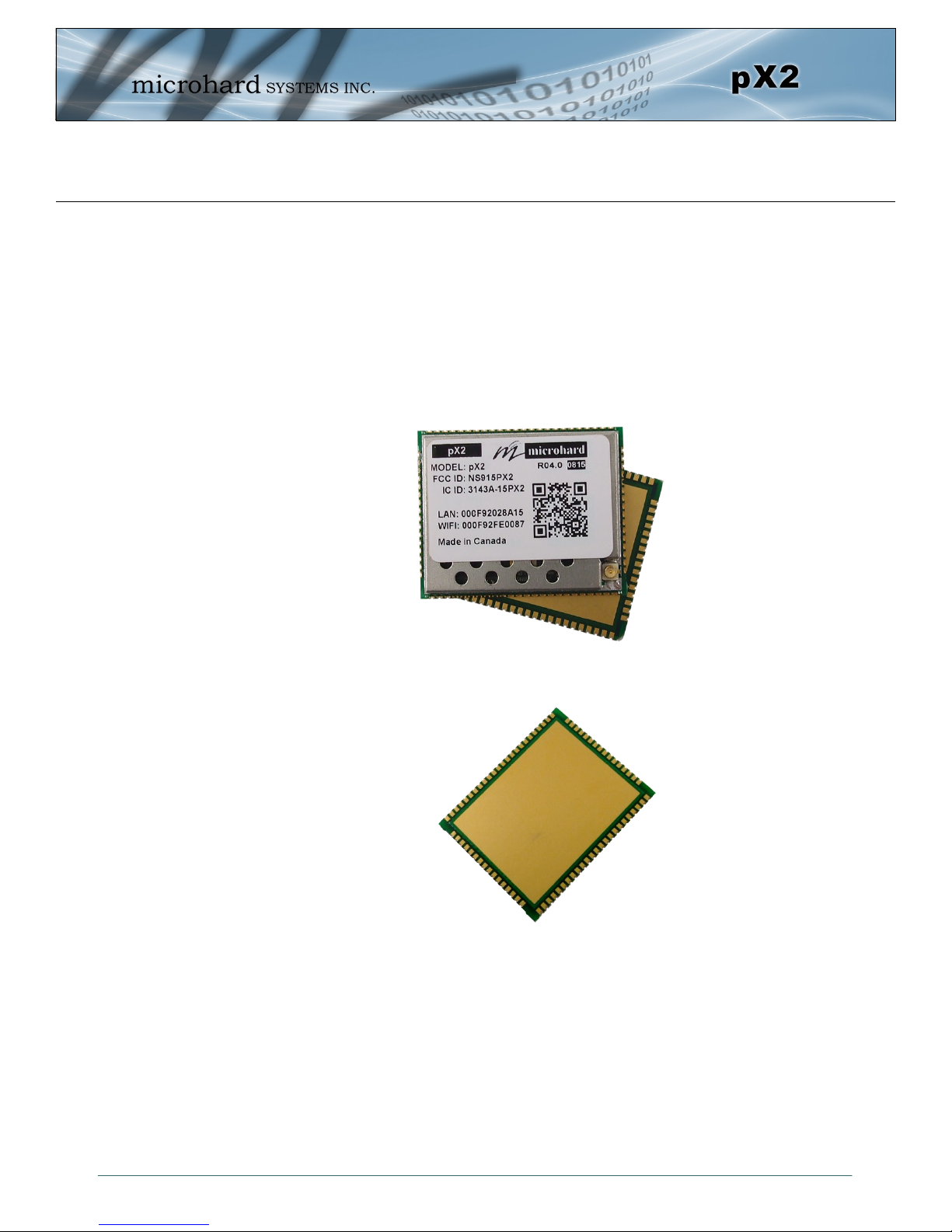
3.0 Hardware Features
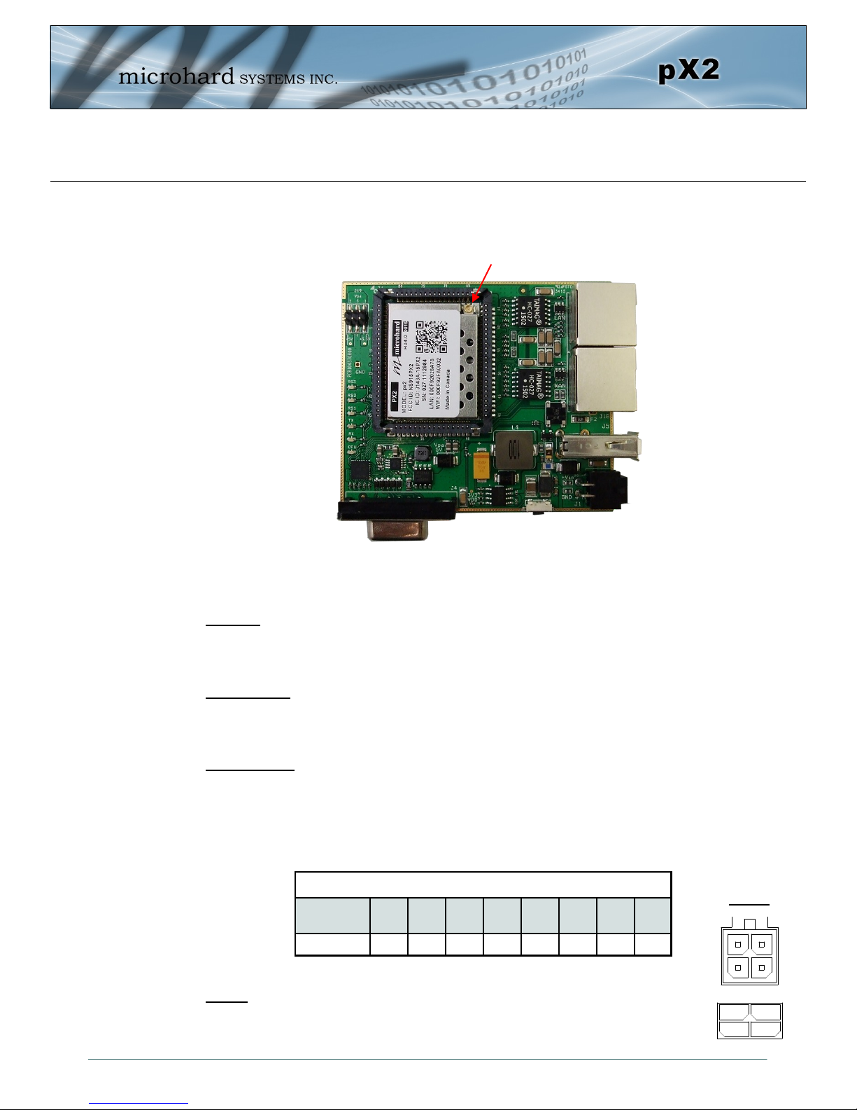
3.1 pX2 OEM Module
The pX2 modems are available as a low cost OEM modules. This OEM version supplies all the required
raw signals to allow the unit to be tightly integrated into applications to efficiently maximize space and
power requirements. The Microhard development board can provide a convenient evaluation platform to
test and design with the module. (Contact Microhard Systems for details)
Any pX2 module may be configured as a Access Point (AP), AP Station, or Repeater. This versatility is
very convenient from a ’sparing’ perspective, as well for convenience in becoming familiar and proficient
with using the module: if you are familiar with one unit, you will be familiar with all units.
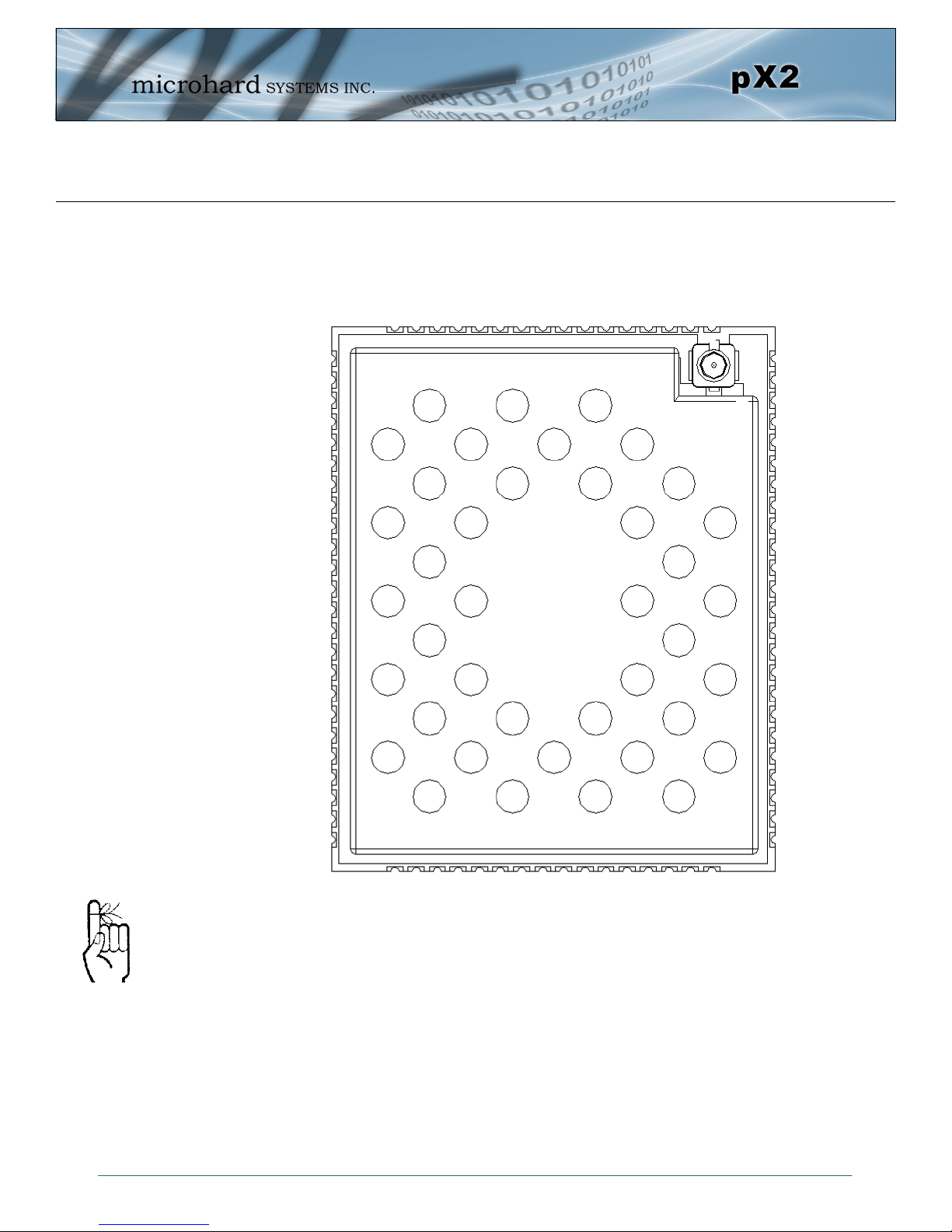
Image 3-1: pX2 Top View
Image 3-2: pX2 Bottom View
© Microhard Systems Inc. 21
Page 22
3.0 Hardware Features
33
26.5
3.68
2.31
33
3.5
0.80
1.27
1.18
22.35
28.70
30.01
2.16
19.85
1.50
3.41
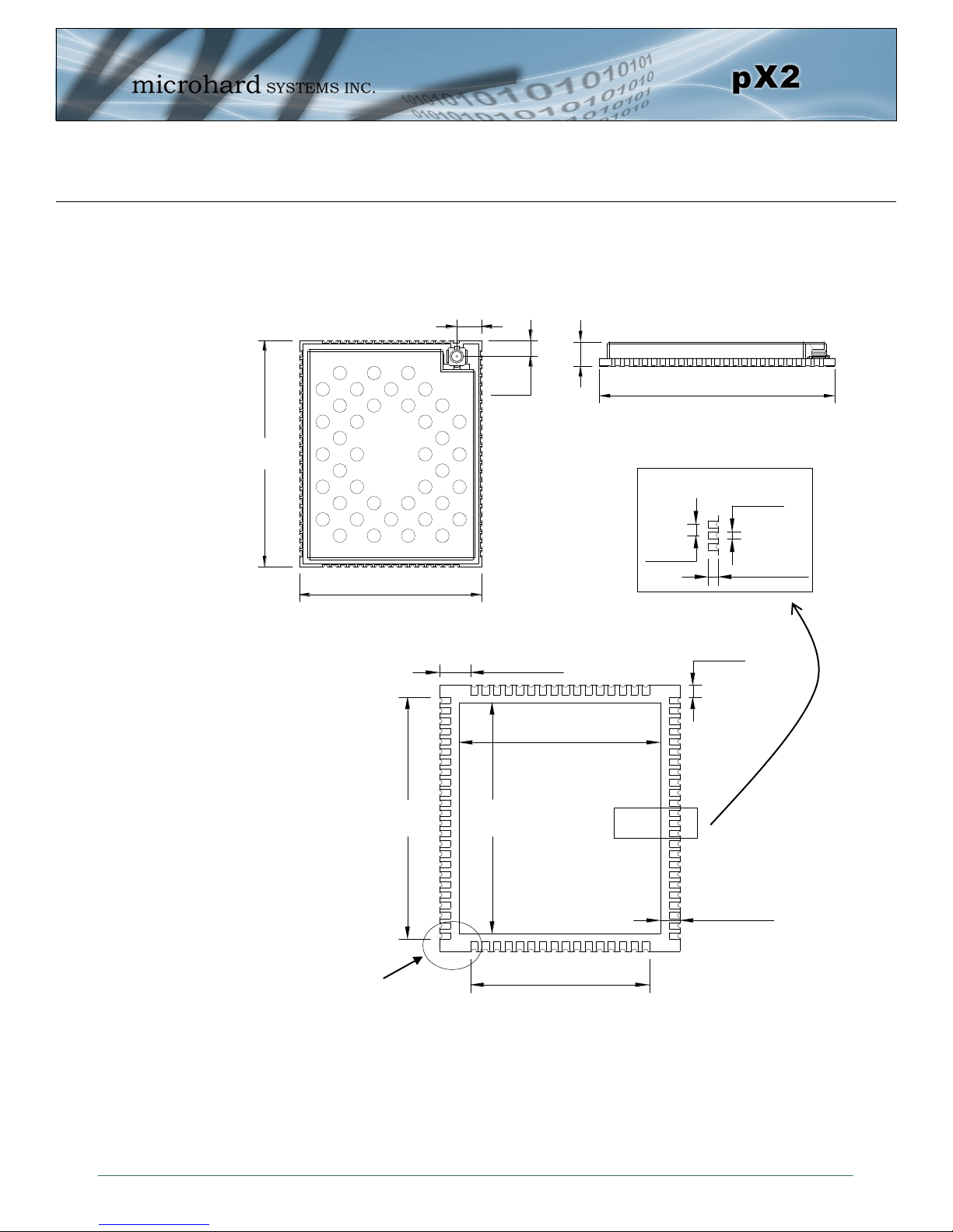
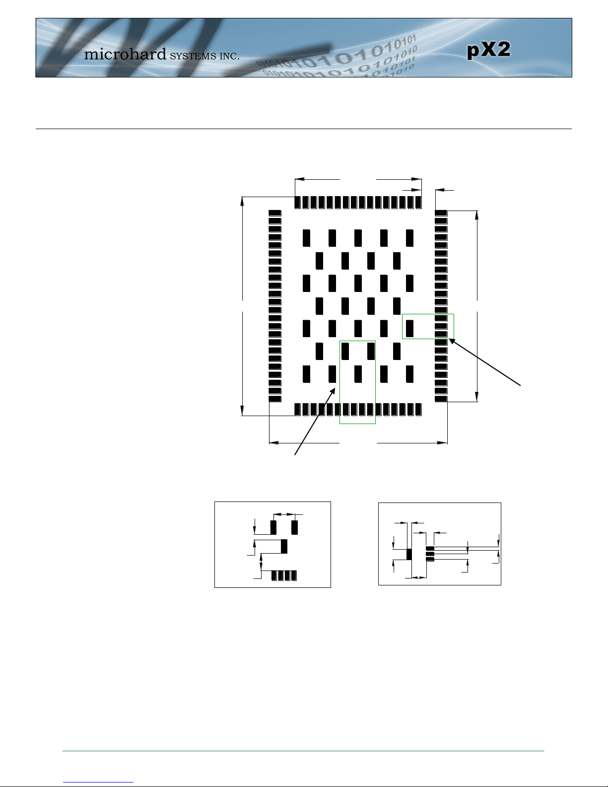
3.1.1 Mechanical Drawings
The pX2 OEM Modules have an extremely small form factor as seen below.
(2)
(2)
(A)
Detail
(2)
© Microhard Systems Inc. 22
See Notes
(2)
Units: millimeters
Ground Plane
Bottom View
Drawing 3-1: pX2 OEM Mechanical
(1)
Detail
1. Ground plane must be connected to GND for required heat dissipation.
2. Due to manufacturing methods additional PCB material may be
present on the corners that cannot be removed. Designs should
allow for a small tolerance of this additional material, ± 0.25mm
(A)
Page 23
3.0 Hardware Features
1.27
0.81
1.83
22.35
30.02
0.99
19.86
28.70
27.99
34.34
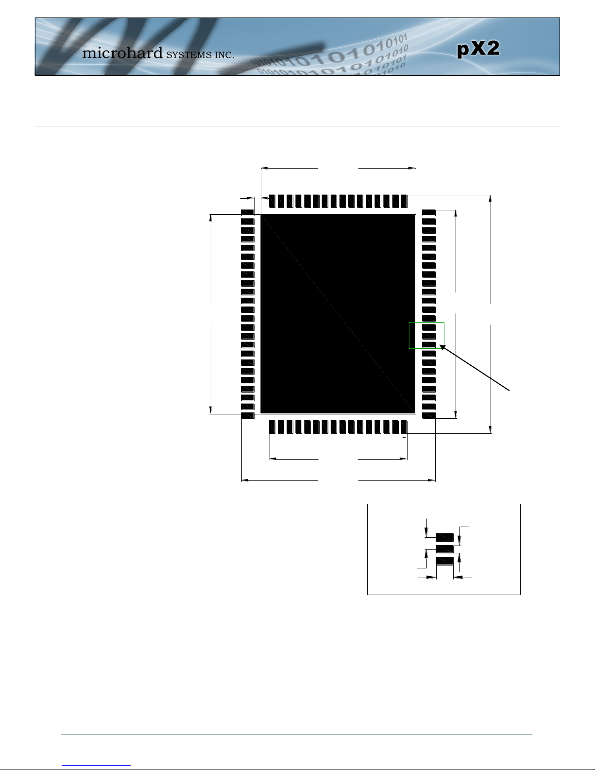
3.1.2 Recommended Solder Mask (Pad Landing)
Units: millimeters
Drawing 3-2: pX2 Recommended Solder Mask
Detail
(B)
Detail
(B)
© Microhard Systems Inc. 23
Page 24
3.0 Hardware Features
19.91
30.0734.39
28.04
2.18
1.88
2.55
1.27
1.03
0.86
3.50
3.38
4.12
1.00
3.1.3 Recommended Solder Paste Pattern
Detail
(C)
(D)
Detail
Units: millimeters
3.1.4 OEM Connectors
Detail
(D)
(C)
Detail
Drawing 3-3: pX2 Recommended Solder Paste
Antenna
All pX2 OEM Modules use an UFL connector for the antenna connection.
Data
The interface to the pX2 OEM module is a tight integration using 80 pad SMT connections.
© Microhard Systems Inc. 24
Page 25
3.0 Hardware Features
3.1.5 Pico OEM Pin Descriptions
GND
DNC
DNC
DNC
DNC
DNC
NC
NC
NC
NC
CPU STATUS LED
NC
ETH_BIAS
USB_MODE
CONFIG
RESET
GND
USBA_DP
USBA_DM
RSSI LED1
RSSI LED2
RSSI LED3
LED RX
LED TX
GND
GND
GND
GND
GND
GND
GND
GND
GND
GND
80 79 78 77 76 75 74 73 72 71 70 69 68
1
2
3
4
5
6
7
8
9
10
11
12
13
14
15
16
17
18
19
20
21
22
23
24
pX2
(Top View)
GND
GND
GND
GND
GND
GND
67 66 65
64
VRF
63
VRF
62
Vcc
61
Vcc
60
ETH0 LINK_LED (LAN)
59
NC
58
RX_P0 (LAN)
57
RX_N0 (LAN)
56
TX_N0 (LAN)
55
TX_P0 (LAN)
54
NC
53
NC
52
NC
51
NC
50
NC
49
ETH4 LINK_LED (WAN)
48
NC
47
NC
46
NC
45
NC
44
TX_P4 (WAN)
43
TX_N4 (WAN)
42
RX_P4 (WAN)
41
40 39 38 37 36 35 34 33 32 31 30 29 28 27 26 25
RX_N4 (WAN)
Inputs and outputs are
3.3V nominal (3.0V min
— 3.6V max) unless
otherwise specified.
The above drawing depicts a top view of the pX2 OEM Module. The corner pads (1, 25, 41,
and 65) are printed directly on the bottom of the PCB for easy identification.
A full description of the connections and function of each pin is provided on the pages that
follow.
© Microhard Systems Inc. 25
GND
Serial RxD
GND
NC
Serial TxD
Serial DSR
Serial CTS
Serial DTR
NC
Serial RTS
NC
Drawing 3-4: pX2 80-pin OEM Connection Info
NC
NC
NC
GND
GND
Page 26
3.0 Hardware Features
Pin Name No. Description Dir
GND 1,17,25-26,39-
DNC 2,3,4,5,6 Reserved for factory use only.
NC 7,8,9,10,12,27,
CPU STATUS
LED
ETH_BIAS 13 Bias Voltage to Ethernet PHY transformer
USB_MODE 14 Indicates if the interfac e is in host/device mode. 0 = Device, 1 = Host. I
Config 15 Active low. In normal mode, pull it low and hold for more than 8 s econds
RESET 16 Active low input will reset module I
Caution: During power up
or reset, output pins from
the Pico are in an unknown
state. It is advised to use
pull up or pull down
resisters as appropriate.
USBDP 18 USB D- signal; carries USB data to and from the USB 2.0 PHY
USBDM 19 USB D+ signal; carries USB data to and from the USB 2.0 PHY
LED_1 (RSSI1) 20 Receive Signal Strength Indicator 1. Active high, cannot drive LED
LED_2 (RSSI2) 21 Receive Signal Strength Indicator 2. Active high, cannot drive LED
LED_3 (RSSI3)
LED_RX 23 Active high output indicates receive and synchronization status. Active
LED_TX 24 Active high output indicates module is transmitting data over the RF
Serial RxD 28 Receive Data. Logic level input into the modem. It is recommended to
Serial TxD 29 Transmit Data. Logic level Output from the modem. It is recommended
Serial DSR 30
Serial CTS 31 Clear To Send. Active low output. O
Serial DTR 32 Data Terminal Ready. Active Low output. O
Serial RTS 34 Request To Send. Active low input. I
40,65-80
33,35,36,37,38,
45,46,47,48,50,
51,52,53,54,59
11 Active high output indicates CPU/Module status. Active high, cannot
22
Ground reference for logic, radio, and I/O pins.
*Currently Not Supported. For Future Expansion*
drive LED directly. Requires current limiting resistor. 8mA maximum.
will reset the system to default settings. Pull it low upon power up will put
the module into recovery mode.
directly. Requires current limiting resistor. 8mA maximum.
directly. Requires current limiting resistor. 8mA maximum.
Receive Signal Strength Indicator 3. Active high, cannot drive LED
directly. Requires current limiting resistor. 8mA maximum.
high, cannot drive LED directly. Requires current limiting resistor. 8mA
maximum.
channel. Active high, cannot drive LED directly. Requires current
limiting resistor. 8mA maximum.
wire this pin out through a zero ohm resister to a header and jumper
block for external access to the serial port for modem recovery
procedures.
to wire this pin out through a zero ohm resister to a header and jumper
block for external access to the serial port for modem recovery
procedures.
Data Set Ready. Active low output. The DSR line set high enables the
transmitter of the RS485 driver.
Table 3-1: pX2 Pin Description
O
I
O
O
O
O
O
I
O
O
All serial communications signals are logic level (0 and 3.3V). DO NOT connect RS-232 level (+12, 12VDC) signals to these lines without shifting the signals to logic levels.
© Microhard Systems Inc. 26
Page 27
3.0 Hardware Features
Pin Name No. Description Dir
RX_N4 41
RX_P4 42
TX_N4 43
TX_P4 44
ETH4 LINK_LED 49 Active high output indicates Ethernet port 4 link status. Active high, cannot drive
TX_P0 55
TX_N0 56
RX_N0 57
RX_P0 58
Caution: During power up
or reset, output pins from
the Pico are in an unknown
state. It is advised to use
pull up or pull down
resisters as appropriate.
ETH0 LINK_LED 60 Active high output indicates Ethernet port 0 link status. Active high, cannot drive
Vdd 61,62 Positive voltage supply voltage for the digital section of the module (3.3V). I
Vpa 63,64 Positive voltage supply voltage for the radio module (3.3-5V). I
All serial communications signals are logic level (0 and 3.3V). DO NOT connect RS-232 level (+12, 12VDC) signals to these lines without shifting the signals to logic levels.
See Appendix D: Sample Interface Schematic for a sample schematic that can be used to interface to
the pX2 OEM module.
Ethernet Port 4 (WAN) Receive Pair
Ethernet Port 4 (WAN) Transmit Pair
O
LED directly. Requires current limiting resistor. 8mA maximum.
Ethernet Port 0 (LAN) Transmit Pair
Ethernet Port 0 (LAN) Receive Pair
O
LED directly. Requires current limiting resistor. 8mA maximum.
Table 3-1: pX2 Pin Description (continued)
© Microhard Systems Inc. 27
Page 28
3.0 Hardware Features
3.2 pX2 Development Board
The pX2 Development board provides a platform in which to test and evaluate the operation of the pX2
without the need to design a custom interface PCB right from the start. The pX2 includes a socket to insert
the pX2 and provides standard interfaces/indicators for:
- Ethernet
- RS232 Serial Port
- USB Port (Not currently supported)
- Power (9-30 VDC)
- CPU Status LED
- Tx/Rx LED’s
- RSSI (x3) LED’s
- Config Button (Reset/Recovery Operations)
- Vpa (3/5V) Jumper Block
© Microhard Systems Inc. 28
Image 3-3: pX2 Development Board
Page 29
3.0 Hardware Features
Vin-
Vin+
GND
GND
Tx-
Tx+
Rx+
Rx-
In
Out
3.2.1 pX2 Development Board Connectors & Indicators
Antenna (UFL)
*Note Antenna Position*
Vpa 3/5V
RSSI LEDs
TX/RX LEDs
CPU/Status
Config Button
RS232 Serial
Figure 3-1: pX2 Development Board
Ethernet (LAN)
Ethernet (WAN)
USB (Future Use)
Power
Antenna:
The pX2 OEM module uses a UFL connector, Ensure proper orientation as seen above to prevent damage
to the pX2 module and to the development board.
Ethernet LAN:
The Ethernet LAN port is a standard RJ45 port to connect local network devices. The default IP address for
this port is 192.168.168.1.
Ethernet WAN:
The Ethernet WAN port is a standard RJ45 Port that can be used as a separate WAN port for Router
functions, or can be bridged (via software) to the LAN as a additional switch port for local devices.
The pX2 development board can be powered using Passive PoE on the WAN port using a PoE injector
that meets the following requirements:
Source
Voltage
9 - 30 Vdc Data Data Data DC+ DC+ Data DC- DC-
Ethernet RJ45 Connector Pin Number
Power
1 2 3 4 5 6 7 8
Table 3-2: Ethernet (WAN) PoE Connections
Power:
The pX2 development board can powered using an input voltage in the 9-30 VDC range.
© Microhard Systems Inc. 29
Page 30
3.0 Hardware Features
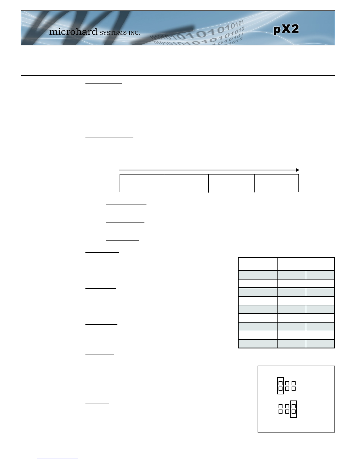
Config Button:
The Config button on the pX2 can be used to either reset the modem into its factory default configuration,
or it can be used to perform a firmware recovery procedure.
Factory Default Settings: While power applied and the pX2 in an operational state, press and hold the
Config Button for 8-10 seconds or until the module reboots. It will reboot with the factory default
configuration settings.
Firmware Recovery: To load the firmware on the unit it is recommended to use the normal WebUI to
perform a firmware update (Maintenance). In the event that the firmware cannot be loaded using the
standard WebUI (non responsive unit), pressing and holding the Config Button while powering-up the
module will force the pX2 into a firmware recovery mode. There are 3 main modes, HTTP, TFTP and
Master Reset. The table below shows the time required to hold the Config button while power is applied:
HTTP Recovery: Set an IP on a PC to 192.168.1.1. Open a web browser and Navigate to
192.168.1.39. This will open a simple webpage which will allow a firmware file to be loaded.
TFTP Recovery: Set an IP on a PC to 192.168.1.1. Use a TFTP session to push the firmware file
to the modems recovery IP of 192.168.1.39. See Appendix for Firmware Recovery Procedure.
Master Reset: Runs Master Reset, file system is erased.
RS232 Serial:
The RS232 Serial data port can be used to communicate with
RS232 Serial devices or it can be configured to operate as a
console port. See Table 3-3 for pin assignments.
CPU/Status:
The CPU/Status LED indicates that power has been applied to
the module. A Solid LED indicates normal operation, while
flashing indicates boot or firmware upgrade status.
TX/RX LEDs:
The TX/RX LEDs indication wireless traffic to/from the pX2
module.
RSSI LEDs:
The RSSI LEDs indicate the Received Signal Strength on the Wireless
Link. On a Access Point it will indicate an average RSSI value based on
connected units. On a Client/Station the RSSI LEDs will represent the
signal strength between the Station and the AP it is connected to. (The
more LEDs illuminated, the stronger the signal)
Vpa 3/5V:
The Vpa jumper allows the radio inside the pX2 to be connected to 3.3
or 5VDC. For the pX2 to operate at maximum output Transmit (Tx)
power of 1 Watt (30dBm), the Vpa jumper must be set to 5VDC (Pin
5+6).
0 to 5 seconds
HTTP Recovery
5 to 10 seconds
TFTP Recovery
10 to 15 seconds
Master Reset
15+ seconds
No Effect
Name Data Port Input or
DCD 1 O
RXD 2 O
TXD 3 I
DTR 4 I
SG 5
DSR 6 O
RTS 7 I
CTS 8 O
RING 9 O
Table 3-3: Data RS232 Pin Assignment
Output
Vpa Jumper
5
1
5VDC
6
5
2
1
3.3VDC
6
2
© Microhard Systems Inc. 30
Page 31

4.0 Configuration
4.0 Web User Interface
The factory default network
settings:
IP: 192.168.168.1
Subnet: 255.255.255.0
Gateway: 192.168.168.1
Image 4-0-1: WebUI
Initial configuration of an pX2 using the W eb User (Browser) Interface (Web UI) method involves the
following steps:
configure a static IP Address on your PC to match the default subnet or if your PC is configured for
DHCP, simply connect a PC to the LAN port of the PX2 and it will be assigned a IP address
automatically.
connect the pX2 ETHERNET(LAN) port to PC NIC card using an Ethernet cable
apply power to the pX2 and wait approximately 60 seconds for the system to load
open a web browser and enter the factory default IP address (192.168.168.1) of the unit:
logon window appears; log on using default Username: admin Password: admin
use the web browser based user interface to configure the pX2 as required.
refer to Section 2.0: Quick Start for step by step instructions.
In this section, all aspects of the Web Browser Interface, presented menus, and available configuration
options will be discussed.
© Microhard Systems Inc. 31
Page 32

4.0 Configuration
For security, do not allow the
web browser to remember the
User Name or Password.
It is advisable to change the
login Password. Do not
FORGET the new password
as it cannot be recovered.
4.0.1 Logon Window
Upon successfully accessing the pX2 using a Web Browser, the Logon window will appear.
Image 4-0-2: Logon Window
The factory default User Name is: admin
The default password is: admin
Note that the password is case sensitive. It may be changed (discussed further along in this section), but
once changed, if forgotten, may not be recovered.
When entered, the password appears as ’dots’ as shown in the image below. This display format prohibits
others from viewing the password.
The ‘Remember my password’ checkbox may be selected for purposes of convenience, however it is
recommended to ensure it is deselected - particularly once the unit is deployed in the field - for one
primary reason: security.
© Microhard Systems Inc. 32
Image 4-0-3: Logon Window : Password Entry
Page 33

4.0 Configuration
4.1 System
The main category tabs located at the top of the navigation bar separate the configuration of the pX2 into
different groups based on function. The System Tab contains the following sub menu’s:
Summary - Status summary of entire radio including network settings,
version information, and radio connection status.
Settings - Host Name, System Log Settings, System Time/Date.
Services - Enable/Disable and configure port numbers for SSH, Telnet, HTTP
and HTTPS services.
Maintenance - Remote firmware Upgrades, reset to defaults, configuration backup
and restore.
Reboot - Remotely reboot the system.
4.1.1 System > Summary
The System Summary screen is displayed immediately after initial login, showing a summary and status of
all the functions of the pX2 in a single display. This information includes System Status, Carrier Status,
Cellular & LAN network information, version info, etc.
© Microhard Systems Inc. 33
Image 4-1-1: System Summary Window
Page 34

4.0 Configuration
4.1.2 System > Settings
System Settings
Options available in the System Settings menu allow for the configuration of the Host Name, Description,
Console Timeout, System Log server and System Time settings.
Image 4-1-2: System Settings > System Settings
Host Name
The Host Name is a convenient identifier for a specific pX2 unit. This
feature is most used when accessing units remotely: a convenient
cross-reference for the unit’s WAN IP address. This name appears
when logged into a telnet session.
Description
The description is a text field that can be used to describe the unit or
system. This value can be viewed on the System > Summary screen.
Console Timeout (s)
This value determines when a console connection (made via Console
Port or Telnet) will timeout after becoming inactive.
Values (characters)
pX2 (varies)
up to 64 characters
Values (characters)
pX2 (varies)
up to 64 characters
Values (seconds)
60
0-65535
© Microhard Systems Inc. 34
Page 35

4.0 Configuration
CFG Reset to Default Button
Enabled by default, when the CFG button on the front of the pX2 is held
down for 10s while the unit is powered up, the unit will reset and all settings
will be reset to factory defaults. When disabled the unit will reset, but the
settings will not be overwritten.
Values (Selection)
Enable
Disable
System Log Server IP
The pX2 can report system level events to a third party System Log server,
which can be used to monitor events reported by the PX2.
IP Address
0.0.0.0
System Log Server Port
Enter the UDP listening port of the System Log Server. The default port
number is generally 514, but could vary from Server to Server.
Time Settings
The pX2 can be set to use a local time source, thus keeping time on its own, or it can be configured to
synchronize the date and time via a NTP Server. The options and menus available will change depending
on the current setting of the Date and Time Setting Mode, as seen below.
UDP Port
514
Network Time Protocol (NTP)
can be used to synchronize the
time and date or computer
systems with a centralized,
referenced server. This can
help ensure all systems on a
network have the same time
and date.
Select the Date and Time Setting Mode required. If set for ‘Local Time’
the unit will keep its own time and not attempt to synchronize with a
network server. If ‘NTP’ is selected, a NTP server can be defined.
© Microhard Systems Inc. 35
Image 4-1-3: System Settings > Time Settings
Date and Time Setting Mode
Values (selection)
Local Time
NTP
Page 36

4.0 Configuration
Date
The calendar date may be entered in this field. Note that the entered
value is lost should the pX2 lose power for some reason.
Time
The time may be entered in this field. Note that the entered value is
lost should the pX2 lose power for some reason.
If connecting to a NTP time server, specify the time zone from the
dropdown list.
This displays the POSIX TZ String used by the unit as determined by
the Timezone setting.
Enter the IP Address or domain name of the desired NTP time server.
Values (yyyy-mm-dd)
2016-01-12 (varies)
Values (hh:mm:ss)
11:27:28 (varies)
Timezone
Values (selection)
(varies)
POSIX TZ String
Values (read only)
(varies)
NTP Server
Values (address)
Enter the IP Address or domain name of the desired NTP time server.
By default the modem only synchronizes the time and date during
system boot up (default: 0), but it can be modified to synchronize at a
regular interval. This process does consume data and should be set
accordingly.
pool.ntp.org
NTP Port
Values (port#)
123
NTP Client Interval
Values (seconds)
0
© Microhard Systems Inc. 36
Page 37

4.0 Configuration
4.1.3 System > Services
Certain services in the pX2 can be disabled or enabled for either security considerations or resource/power
considerations. The Enable/Disable options are applied after a reboot and will take affect after each start
up. The Start/Restart/Stop functions only apply to the current session and will not be retained after a power
cycle.
Image 4-1-4: System > Services
The FTP service can be enabled/disabled using the Services Status
Menu. The FTP service is used for firmware recovery operations.
Using the Telnet Service Enable/Disable function, you can disable the
Telnet service from running on the pX2. The port used by the Telnet
service can also be modified. The default is 23.
Using the SSH Service Enable/Disable function, you can disable the
SSH service (Port 22) from running on the pX2. The port used by the
SSH service can also be modified. The default is 22.
The default web server port for the web based configuration tools used
in the modem is port 80 (http) and port 443 (HTTPS).
Change as required, but keep in mind that if a non standard port is
used, it must be specified in a internet browser to access the unit.
(example: http://192.168.168.1:8080).
FTP
Values (port)
Enable / Disable
Telnet
Values (port)
23
SSH
Values (port)
22
Web UI
Values (selection)
HTTP/HTTPS
HTTP
HTTPS
Microhard Sh is reserved for internal use.
© Microhard Systems Inc. 37
Page 38

4.0 Configuration
4.1.4 System > Maintenance
Firmware Upgrade
Occasional firmware updates may be released by Microhard Systems which may include fixes and/or new
features. The firmware can be updated wirelessly using the WebUI.
Image 4-1-5: Maintenance > Firmware Upgrade
Erase Current Configuration
Choose to keep or erase the current configuration. Erasing the
configuration of the pX2 unit during the upgrade process will upgrade,
and return the unit to factory defaults, including the default IP Address
and password.
Values (check box)
Keep ALL Configuration
Erase Configuration
Firmware Image
Use the Browse button to find the firmware file supplied by Microhard
Systems. Select “Upgrade Firmware” to start the upgrade process.
This can take several minutes.
Reset to Default
The pX2 may be set back to factory defaults by using the Reset to Default option under System >
Maintenance > Reset to Default. *Caution* - All settings will be lost!!!
Values (file)
(no default)
© Microhard Systems Inc. 38
Page 39

4.0 Configuration
Backup & Restore Configuration
The configuration of the pX2 can be backed up to a file at any time using the Backup Configuration feature.
The file can the be restored using the Restore Configuration feature. It is always a good idea to backup
any configurations in case of unit replacement. The configuration files cannot be edited offline, they are
used strictly to backup and restore units.
Image 4-1-6: Maintenance > Reset to Default / Backup & Restore Configuration
Configuration File Name / Backup
Use this field to name the configuration file. The .config extension will automatically be added to the
configuration file.
Select Configuration file / Check Configuration File / Restore
Use the ‘Browse’ button to find the backup file that needs to be restored to the unit. Use the ‘Check
Restore File’ button to verify that the file is valid, and then the option to restore the configuration is
displayed, as seen above.
© Microhard Systems Inc. 39
Page 40

4.0 Configuration
4.1.5 System > Reboot
The pX2 can be remotely rebooted using the System > Reboot menu. As seen below a button ‘OK, reboot
now’ is provided. Once pressed, the unit immediately reboots and starts its boot up procedure.
Image 4-1-7: System > Reboot
© Microhard Systems Inc. 40
Page 41

4.0 Configuration
4.2 Network
4.2.1 Network > Status
The Network Summary display gives a overview of the currently configured network interfaces including
the Connection Type (Static/DHCP), IP Address, Net Mask, Default Gateway, DNS, and IPv4 Routing
Table.
© Microhard Systems Inc. 41
Image 4-2-1: Network > Network Status
Page 42

4.0 Configuration
4.2.2 Network > LAN
LAN Port Configuration
The LAN Ethernet port(s) on the pX2 are for connection of devices on a local network. By default, this port
has a static IP Address. It also, by default is running a DHCP server to provide IP Addresses to devices
that are connected to the physical LAN port (directly or via a switch).
DHCP: Dynamic Host
Configuration Protocol may
be used by networked
devices (Clients) to obtain
unique network addresses
from a DHCP server.
Advantage:
Ensures unique IP addresses
are assigned, from a central
point (DHCP server) within a
network.
Disadvantage:
The address of a particular
device is not ‘known’ and is
also subject to change.
STATIC addresses must be
tracked (to avoid duplicate
use), yet they may be
permanently assigned to a
device.
Within any IP network, each
device must have its own
unique IP address.
Image 4-2-2: Network > Network LAN Configuration
LAN Add/Edit Interface
The pX2 has the capability to have multiple SSID’s for the WiFi radio. New Interfaces can be added for
additional SSID’s, providing, if required, separate subnets for each SSID. By default any additional
interfaces added will automatically assign IP addresses to connecting devices via DHCP. Additional
interfaces can only be used by additional WIFI SSID’s (virtual interfaces).
© Microhard Systems Inc. 42
Image 4-2-3: Network > LAN Port Configuration
Page 43

4.0 Configuration
Spanning Tree (STP)
The factory default
network settings:
IP: 192.168.168.1
Subnet: 255.255.255.0
Gateway: 192.168.168.1
A SUBNET MASK is a bit
mask that separates the
network and host (device)
portions of an IP address.
The ‘unmasked’ portion
leaves available the
information required to
identify the various devices
on the subnet.
This option allows the pX2 to participate in the Spanning Tree protocol
with other devices to prevent local loops. By default this is disabled.
This selection determines if the pX2 will obtain an IP address from a
DHCP server on the attached network, or if a static IP address will be
entered. If a Static IP Address is chosen, the fields that follow must
also be populated.
If ‘Static’ Connection Type is selected, a valid IPv4 Address for the
network being used must be entered in the field. If ‘DHCP’ is chosen
this field will not appear and it will be populated automatically from the
DHCP server.
If ‘Static’ Connection Type is selected, the Network Mask must be
entered for the Network. If ‘DHCP’ is chosen this field will not appear
and it will be populated automatically from the DHCP server.
Values (selection)
Off
On
Connection Type
Values (selection)
DHCP
Static
IP Address
Values (IP Address)
192.168.168.1
Netmask
Values (IP Address)
255.255.255.0
A GATEWAY is a point within
a network that acts as an
entrance to another network.
In typical networks, a router
acts as a gateway.
Within any IP network, each
device must have its own
unique IP address.
Default Gateway
If the pX2 is integrated into a network which has a defined gateway,
then, as with other hosts on the network, this gateway’s IP address will
be entered into this field. If there is a DHCP server on the network,
and the Connection Type (see previous page) is selected to be DHCP,
the DHCP server will populate this field with the appropriate gateway
address.
A simple way of looking at what the gateway value should be is: If a device has a packet of data is does
not know where to send, send it to the gateway. If necessary - and applicable - the gateway can forward
the packet onwards to another network.
Values (IP Address)
(no default)
DNS
Set the DNS (Domain Name Server) for use by devices on the LAN
port, if required.
Values (IP Address)
(no default)
© Microhard Systems Inc. 43
Page 44

4.0 Configuration
LAN DHCP
A pX2 may be configured to provide dynamic host control protocol (DHCP) service to all attached (either
wired or wireless (WiFi)-connected) devices. By default the DHCP service is enabled, so devices that are
connected to the physical Ethernet LAN ports, as well as any devices that are connected by WiFi will be
assigned an IP by the pX2. The LAN DHCP service is available for each interface, and is located in the
add/edit interface menus.
Image 4-2-4: Network > DHCP Server
Prior to enabling this service,
verify that there are no other
devices - either wired (e.g.
LAN) or wireless with an
active DHCP SERVER
service. (The Server issues
IP address information at the
request of a DHCP Client,
which receives the
information.)
The option is used to enable or disable the DHCP service for devices
connected to the LAN Port(s).
Select the starting address DHCP assignable IP Addresses. The first
octets of the subnet will be pre-set based on the LAN IP configuration,
and can not be changed.
Set the maximum number of IP addresses that can be assigned by the
pX2.
The DHCP lease time is the amount of time before a new request for a
network address must be made to the DHCP Server.
DHCP Server
Values (selection)
Enable / Disable
Start
Values (IP Address)
192.168.168.100
Limit
Values (integer)
150
Lease Time
Values (minutes)
720
Alternate Gateway
Specify an alternate gateway for DHCP assigned devices if the default
gateway is not to be used.
© Microhard Systems Inc. 44
Values (IP Address)
(IP Address)
Page 45

4.0 Configuration
Preferred DNS Server
DNS: Domain Name Service
is an Internet service that
translates easilyremembered domain names
into their not-so-easilyremembered IP addresses.
Being that the Internet is
based on IP addresses,
without DNS, if one entered
the domain name
www.microhardcorp.com (for
example) into the URL line of
a web browser, the website
‘could not be found’).
Specify a preferred DNS server address to be assigned to DHCP
devices.
Specify the alternate DNS server address to be assigned to DHCP
devices.
Enter the Domain Name for the DHCP devices.
Enter the address of the WINS/NBNS (NetBIOS) Server. The WINS
server will translate computers names into their IP addresses, similar
to how a DNS server translates domain names to IP addresses.
Select the method used to resolve computer names to IP addresses.
Four name resolution methods are available:
B-node: broadcast
P-node: point-to-point
M-node: mixed/modified
H-node: hybrid
Values (IP Address)
(IP Address)
Alternate DNS Server
Values (IP Address)
(IP Address)
Domain Name
Values (string)
(IP Address)
WINS/NBNS Servers
Values (IP/Domain)
(no default)
WINS/NBT Node Type
Values (selection)
none
b-node
p-node
m-node
h-node
© Microhard Systems Inc. 45
Page 46

4.0 Configuration
Static IP Addresses (for DHCP)
In some applications it is important that specific devices always have a predetermined IP address. This
section allows for MAC Address binding to a IP Address, so that whenever the device that has the
specified MAC address, will always get the selected IP address. In this situation, all attached (wired or
wireless) devices can all be configured for DHCP, but still get a known IP address.
Image 4-2-5: Network > MAC Address Binding
Name
The name field is used to give the device a easily recognizable name.
Values (characters)
(no default)
MAC Address
Enter in the MAC address of the device to be bound to a set IP
address. Set the IP Address in the next field. Must use the format:
AB:CD:DF:12:34:D3. It is not case sensitive, but the colons must be
present.
Values (MAC Address)
(no default)
IP Address
Enter the IP Address to be assign to the device specified by the MAC
address above.
Static Addresses
This section displays the IP address and MAC address currently assigned through the DCHP service, that
are bound by it’s MAC address. Also shown is the Name, and the ability to remove the binding by clicking
“Remove _______”.
Active DHCP Leases
This section displays the IP Addresses currently assigned through the DCHP service. Also shown is the
MAC Address, Name and Expiry time of the lease for reference.
Values (IP Address)
(minutes)
© Microhard Systems Inc. 46
Page 47

4.0 Configuration
4.2.3 Network > WAN
WAN Configuration
The WAN configuration refers to the wired WAN connection on the pX2. The WAN port can be used to
connect the pX2 to other networks, the internet and/or other network resources.
DHCP: Dynamic Host
Configuration Protocol may
be used by networked
devices (Clients) to obtain
unique network addresses
from a DHCP server.
Advantage:
Ensures unique IP addresses
are assigned, from a central
point (DHCP server) within a
network.
Disadvantage:
The address of a particular
device is not ‘known’ and is
also subject to change.
STATIC addresses must be
tracked (to avoid duplicate
use), yet they may be
permanently assigned to a
device.
Image 4-2-6: Network > WAN Configuration
Use this to set the function of the physical WAN RJ45 port. If set to
independent WAN , the physical WAN port will operate as a standard
WAN port. Alternatively it can be configured to be bridged to the LAN,
and operate as a second LAN port, or even as an independent LAN.
This selection determines if the pX2 will obtain an WAN IP address
from a DHCP server, or if a static IP address will be entered. If a Static
IP Address is chosen, the fields that follow must also be populated.
If ‘Static’ Connection Type is selected, a valid IPv4 Address for the
network being used must be entered in the field. If ‘DHCP’ is chosen
this field will not appear and it will be populated automatically from the
DHCP server.
If ‘Static’ Connection Type is selected, the Network Mask must be
entered for the Network. If ‘DHCP’ is chosen this field will not appear
and it will be populated automatically from the DHCP server.
Working Mode
Values (selection)
Independent WAN
Bridged with LAN Port
Independent LAN
Connection Type
Values (selection)
DHCP
Static
IP Address
Values (IP Address)
(no default)
Netmask
Values (IP Address)
(no default)
© Microhard Systems Inc. 47
Page 48

4.0 Configuration
Default Gateway
If the pX2 is integrated into a network which has a defined gateway,
then, as with other hosts on the network, this gateway’s IP address will
be entered into this field. If there is a DHCP server on the network,
and the Connection Type (see previous page) is selected to be DHCP,
the DHCP server will populate this field with the appropriate gateway
address.
Values (IP Address)
(no default)
Default Route
The Default Route parameter allows you to set this interface as the
default route in the routing table. This is result in all data being sent to
the WAN interface if there the destination network is not directly
connected (LAN, WIFI etc), and no other route has been specified. In
cases where the WAN is the primary connection this would be set to
Yes.
DNS Servers
The following section will allow a user to specify DNS Server(s) to be used by the WAN interface of the
pX2.
Values (selection)
No / Yes
Mode
Select between Manual or Auto for DNS server(s) for the WAN
interface. If set to Auto the pX2 will try to automatically detect the DNS
servers to use, which is normally the case when the WAN is DHCP.
Manual required the DNS addresses to be known and entered below.
Values (selection)
Manual / Auto
Primary DNS
DNS (Domain Name Service) Servers are used to resolve domain
names into IP addresses. If set to auto and the Connection Type is set
for DHCP the DHCP server will populate this field and the value set
can be viewed on the Network > Status page. To add additional static
servers, enter them here.
Values (IP Address)
(no default)
Secondary DNS
DNS (Domain Name Service) Servers are used to resolve domain
names into IP addresses. If set to auto and the Connection Type is set
for DHCP the DHCP server will populate this field and the value set
can be viewed on the Network > Status page. To add additional static
servers, enter them here.
© Microhard Systems Inc. 48
Values (IP Address)
(no default)
Page 49

4.0 Configuration
4.2.4 Network > Ports
The Network > Ports menu can be used to determine the characteristics of the physical Ethernet interfaces
on the pX2. As seen below the Mode (Auto/Manual), Auto-Negotiation, Speed (10/100Mbit/s) and the
Duplex (Full/Half) can all be configured on the pX2.
Image 4-2-6: Network > Ports
Mode
If set to Auto, the pX2 will negotiate and determine the best connection
speed and mode.
Enable or disable auto-negotiation.
If the mode and auto negotiation are set you manual the connection
speed can be specified.
Selection between full or half duplex for the direction of data.
Values (selection)
Auto / Manual
Auto-Negotiation
Values (selection)
On / Off
Speed
Values (selection)
100Mbit/s / 10 Mbit/s
Duplex
Values (selection)
Full / Half
© Microhard Systems Inc. 49
Page 50

4.0 Configuration
4.2.4 Network > Device List
The Network > Device List shows the current ARP table for the local network adapter. The MAC address
and IP address are shown, however not only DHCP assigned devices are listed in the device list, any
devices, even those statically assigned, that are connected through the local network interface (s) are
displayed, including those connected through a hub or switch.
Image 4-2-7: Network > Device List
© Microhard Systems Inc. 50
Page 51

4.0 Configuration
4.3 Wireless (WiFi)
4.3.1 Wireless > Status
The Status window gives a summary of all radio or wireless related settings and connections.
The General Status section shows the Wireless MAC address of the current radio, the Operating Mode
(Access Point, Client, MESH etc), the SSID being used, frequency channel information and the type of
security used.
Traffic Status shows statistics about the transmitted and received data.
The pX2 shows information about all Wireless connections in the Connection Info section. The Wireless
MAC address, Noise Floor, Signal to Noise ratio (SNR), Signal Strength (RSSI), The transmit and receive
Client Connection Quality (CCQ), TX and RX data rates, and a graphical representation of the signal level
or quality.
© Microhard Systems Inc. 51
Image 4-3-1: Wireless > Status
Page 52

4.0 Configuration
4.3.2 Wireless > Radio1
Radio1 Phy Configuration
The top section of the Wireless Configuration allows for the configuration of the physical radio module. You
can turn the radio on or off, and select the channel bandwidth and frequency as seen below.
Image 4-3-2: Wireless > Radio Configuration
This option is used to turn the radio module on or off. If turned off
Wireless connections can not be made. The default is On.
The Mode defines which wireless standard to use for the wireless
network. The pX2 supports the 802.11b/g/n modes seen here. Select
the appropriate operating mode from the list.
The options below are dependant and vary on the operating mode
chosen here.
Only appears when using 802.11b, bg or a modes. Lower channel
bandwidths may provide longer range and be less susceptible to noise
but at the trade off of data rates. Higher channel bandwidth may
provide greater data rates but will be more susceptible to noise and
shorter distance potentials.
Radio
Values (selection)
On / Off
Mode
Values (selection)
802.11B ONLY
802.11BG
802.11NG
Channel Bandwidth
Values (selection)
20MHz Normal Rate
© Microhard Systems Inc. 52
Page 53

4.0 Configuration
High Throughput Mode
Select HT20 for a 20MHz channel, or HT40 for a 40 MHz Channel.
The 40MHz channel is comprised of 2 adjacent 20MHz channels and
the + and—designate to use the higher or lower of the adjacent
channels.
Advanced Capabilities (Only shown if box is checked)
MPDU Aggregation (Enable/Disable) - Allows multiple data frames to be sent in a single transmission
block, allowing for acknowledging or retransmitting if errors occur.
Short GI (Enable/Disable) - GI (guard interval) is the time the receiver waits for any RF reflections to settle
before sampling data. Enabling a short GI (400ns) can increase throughput, but can also increase the error
rate in some installations.
HT Capabilities Info - TX-STBC RX-STBC1 DSSS_CCK-40
Maximum AMSDU (byte) - 3839
Maximum AMPDU (byte) - 65535
Values (selection)
HT20
HT40HT40+
Channel-Freq
The Channel-Freq setting allows configuration of which channel to
operate on, auto can be chosen where the unit will automatically pick a
channel to operate. If a link cannot be established it will try another
channel.
Values (selection)
Channel 01 : 2.412 GHz
Channel 02 : 2.417 GHz
Channel 03 : 2.422 GHz
Channel 04 : 2.427 GHz
Channel 05 : 2.432 GHz
Channel 06 : 2.437 GHz
Channel 07 : 2.442 GHz
Channel 08 : 2.447 GHz
Channel 09 : 2.452 GHz
Channel 10 : 2.457 GHz
Channel 11 : 2.462 GHz
This setting establishes the transmit power level which will be
presented to the antenna connector of the pX2. Unless required, the
Tx Power should be set not for maximum, but rather for the minimum
value required to maintain an adequate system fade margin.
Refer to FCC (or as
otherwise applicable)
regulations to ascertain,
and not operate beyond,
the maximum allowable
transmitter output power
and effective isotropic
radiated power (EIRP).
© Microhard Systems Inc. 53
TX Power
Values (selection)
20 dBm
21 dBm
22 dBm
23 dBm
24 dBm
25 dBm
26 dBm
27 dBm
28 dBm
29 dBm
30 dBm
Page 54

4.0 Configuration
Wireless Distance
The Wireless Distance parameter allows a user to set the expected
distance the WiFi signal needs to travel. The default is 100m, so the
pX2 will assume that the signal may need to travel up to 100m so it
sets various internal timeouts to account for this travel time. Longer
distances will require a higher setting, and shorter distances may
perform better if the setting is reduced.
Once the RTS Threshold defined packet size is reached, the system
will invoke RTS/CTS flow control. A large RTS Threshold will improve
bandwidth, while a smaller RTS Threshold will help the system recover
from interference or collisions caused by obstructions.
Fragment Thr (256 ~ 2346)
The Fragmentation Threshold allows the system to change the
maximum RF packet size. Increasing the RF packet size reduces the
need to break packets into smaller fragments. Increasing the
fragmentation threshold slightly may improve performance if a high
packet error rate is experienced.
Values (meters)
100
RTS Thr (256 ~ 2346)
Values (selection)
On / OFF
Values (selection)
On / OFF
© Microhard Systems Inc. 54
Page 55

4.0 Configuration
Radio1 Virtual Interface
The bottom section of the Wireless Configuration provides for the configuration of the Operating Mode of
the Wireless Interface, the TX power, Wireless Network information, and Wireless Encryption. The pX2 can
support multiple virtual interfaces. These interfaces provide different SSID’s for different users, and can
also be assigned to separate subnets (Network Interfaces) to prevent groups from interacting.
Image 4-3-3: Wireless > Radio Configuration
Network
Choose the network Virtual Interface. If additional Network Interfaces
have been defined in the Network > LAN section, the Interface name
will also appear here.
Values (selection)
LAN
(Additional Interfaces…)
Mode
Access Point - An Access Point may provide a wireless data
connection to many clients, such as stations, repeaters, or other
supported wireless devices such as laptops etc.
If more than 1 Virtual Interface (more than 1 SSID) has been defined,
the pX2 can ONLY operate as a Access Point, and will be locked into
this mode.
Station/Client - A Station may sustain one wireless connection, i.e. to an Access Point.
Repeater - A Repeater can be connected to an Access Point to extend the range and provide a
wireless data connection to many clients, such as stations.
Mesh Point - Units can be configured as a Mesh “Node”. When multiple units are configured as a
Mesh node, they automatically establish a network between each other. SSID for each
radio in a Mesh network must be the same.
Values (selection)
Access Point
Client
Repeater
Mesh Point
© Microhard Systems Inc. 55
Page 56

4.0 Configuration
This setting determines the rate at which the data is to be wirelessly transferred.
The default is ‘Auto’ and, in this configuration, the unit will transfer data at the highest possible rate in
consideration of the receive signal strength (RSSI).
Setting a specific value of transmission rate has the benefit of ‘predictability’ of that rate, but if the RSSI
drops below the required minimum level to support that rate, communications will fail.
TX bitrate
802.11 b/g
Auto
1 Mbps (802.11b,g)
2 Mbps (802.11b,g)
5.5 Mbps (802.11b,g)
11 Mbps (802.11b,g)
6 Mbps (802.11g)
9 Mbps (802.11g)
12 Mbps (802.11g)
18 Mbps (802.11g)
24 Mbps (802.11g)
36 Mbps (802.11g)
48 Mbps (802.11g)
54 Mbps (802.11g)
Wireless distribution system (WDS) is a system enabling the wireless
interconnection of access points. WDS preserves the MAC addresses
of client frames across links between access points
Disabling the SSID broadcast helps secure the wireless network.
Enabling the broadcast of the SSID (Network Name) will permit others
to ‘see’ the wireless network and perhaps attempt to ‘join’ it.
802.11n (HT20/HT40)
Auto
mcs-0 (7.2/15) Mbps
mcs-1 (14.4/30.0) Mbps
mcs-2 (21.7/45.0) Mbps
mcs-3 (28.9/60.0) Mbps
mcs-4 (43.3/90.0) Mbps
mcs-5 (57.8/120.0) Mbps
mcs-6 (65.0/135.0) Mbps
mcs-7 (72.2/150.0) Mbps
WDS
Values (selection)
On / Off
ESSID Broadcast
Values (selection)
On / Off
When set in Mesh Mode, the MESH ID must be the same for all pX2
units participating, similar to the SSID for other wireless networks.
When AP Isolation is enabled wireless devices connected to this SSID
will not be able to communicate with each other. In other words if the
pX2 is being used as a Access Point for many wireless clients, AP
Isolation would provide security for those clients by not allowing
access to any other wireless device.
© Microhard Systems Inc. 56
MESH ID
Values
(no default)
AP Isolation
Values (selection)
On / Off
Page 57

4.0 Configuration
WMM
SSID: Service Set Identifier.
The ‘name’ of a wireless
network. In an open wireless
network, the SSID is
broadcast; in a closed system
it is not. The SSID must be
known by a potential client for
it to be able to access the
wireless network.
Change the default value for
the Network Name to
something unique for your
network. Do this for an
added measure of security
and to differentiate your
network from others which
may be operating nearby.
WiFi Multimedia (WMM) is a feature that enhances the quality of
service on a network by prioritizing data packets according to data
type. (Video, Voice, Best Effort, Background).
All devices connecting to the pX2 in a given network must use the
SSID of the pX2. This unique network address is not only a security
feature for a particular network, but also allows other networks - with
their own unique network address - to operate in the same area
without the possibility of undesired data exchange between networks.
The encryption types defines the type of security used for the Wireless
Interface, to join a network a device must know the correct password/
passphrase/key.
Security options are dependent on the version type. This section
describes all available options. Export versions may not have all
optional available to meet regulatory requirements set government
policies.
This is the password, or preshared key that is required by any device
to connect to the wireless interface of the pX2. It is strongly
recommended to always have a password defined, and changed from
the factory default.
Values (selection)
On / Off
SSID
Values (string)
pX2
Encryption Type
Values (selection)
Disabled
WPA (PSK)
WPA2 (PSK)
WPA+WPA2 (PSK)
WPA Enterprise (RADIUS)
WPA2 Enterprise (RADIUS)
WPA+WPA2 Enterprise(RADIUS)
WPA PSK
Values (string)
0123456789
Check this box to show the currently configured password for WPA/
WPA2 encryption passphrase.
© Microhard Systems Inc. 57
Show Password
Values (selection)
unchecked
Page 58

4.0 Configuration
RADIUS IP Address
If using Enterprise (RADIUS) encryption, enter the IP Address of the
RADIUS authentication server here.
If using Enterprise (RADIUS) encryption, enter the port number of the
RADIUS authentication server here.
This is the password, or preshared key that is required by any device
to connect to the wireless interface of the pX2. It is strongly
recommended to always have a password defined, and changed from
the factory default.
Values (IP Address)
(no default)
RADIUS Port
Values (port)
(no default)
RADIUS Server Key
Values (selection)
0123456789
© Microhard Systems Inc. 58
Page 59

4.0 Configuration
4.4 Firewall
4.4.1 Firewall > Summary
The Firewall Summary allows a user to see detailed information about how the firewall is operating. The
All, Filter, Nat, Raw, and Mangle options can be used to view different aspects of the firewall.
© Microhard Systems Inc. 59
Image 4-4-1: Firewall > Status
Page 60

4.0 Configuration
4.4.2 Firewall > General
The General Firewall settings allow users to enable or disable the firewall, and to decide which areas of the
modem to protect. The Firewall can also be reset to factory defaults from this area of the WebUI.
Image 4-4-2: Firewall > General
WAN Remote Management
Allow remote management of the pX2 on the WAN side using the WebUI
on port 80(HTTP), and 443 (HTTPS). If disabled, the configuration can only
be accessed from the LAN.
When Blocked the pX2 will block all requests from devices on the WAN
unless specified otherwise in the Access Rules, MAC List, IP List
configurations. Access to ports 80 (HTTP) and 443 (HTTPS-if enabled), is
still available unless disabled in the WAN Remote Management option.
LAN to WAN Access Control
Allows or Blocks traffic from the LAN accessing the WAN unless specified
otherwise using the Access Rules, MAC, and IP List configuration.
The Anti-Spoof protection is to create some firewall rules assigned to the
external interface (WAN) of the firewall that examines the source address
of all packets crossing that interface coming from outside. If the address
belongs to the internal network or the firewall itself, the packet is dropped.
Values
Enable / Disable
WAN Request
Values
Block / Allow
Values
Block / Allow
Anti-Spoof
Values
Enable / Disable
Packet Normalization
Packet Normalization is the normalization of packets so there are no
ambiguities in interpretation by the ultimate destination of the packet. The
scrub directive also reassembled fragmented packets, protecting some
operating systems from some forms of attack, and drops TCP packets that
have invalid flag combinations.
© Microhard Systems Inc. 60
Values
Enable / Disable
Page 61

4.0 Configuration
Reverse NAT
The Reverse NAT allows access to the modem from the LAN port using the
carrier’s IP address.
Values
Enable / Disable
© Microhard Systems Inc. 61
Page 62

4.0 Configuration
4.4.3 Firewall > Port Forwarding
The pX2 can be used to provide remote access to connected devices. To access these devices a user
must define how incoming traffic is handled by the pX2. If all incoming traffic is intended for a specific
connected device, DMZ could be used to simplify the process, as all incoming traffic can be directed
towards a specific IP address.
In the case where there is multiple devices, or only specific ports need to be passed, Port forwarding is
used to forward traffic coming in from the WAN to specific IP Addresses and Ports on the LAN. Port
forwarding can be used in combination with other firewall features, but the Firewall must be enabled for
Port forwarding to be in effect. If the WAN Request is blocked on the General Tab, additional rules and/or
IP Lists must be set up to allow the port forwarding traffic to pass through the firewall.
If DMZ is enabled and an
exception port for the WebUI
is not specified, remote
management will not be
possible. The default port for
remote management is TCP
80.
Image 4-4-3: Firewall > Port Forw arding
Enable or disable DMZ Mode. DMZ can be used to forward all traffic to the
DMZ Server IP listed below.
Enter the IP address of the device on the LAN side of the pX2 where all the
traffic will be forwarded to.
DMZ Mode
Values (selection)
Disable / Enable
DMZ Server IP
Values (IP Address)
192.168.100.100
© Microhard Systems Inc. 62
Page 63

4.0 Configuration
Exception Port
If the firewall is set to block
incoming traffic on the WAN
and/or Carrier interfaces,
additional rules or IP/MAC
lists must be configured to
allow desired traffic access.
Enter a exception port number that will NOT be forwarded to the DMZ
server IP. Usually a configuration or remote management port that is
excluded to retain external control of the pX2.
Firewall Port Forwarding Configuration
This is simply a field where a convenient reference or description is added
to the rule. Each Forward must have a unique rule name and can use up to
10 characters.
Select the source for the traffic, from either the WIFI or from the WAN.
Enter the IP address of the intended internal (i.e. on LAN side of the pX2)
server. This is the IP address of the device you are forwarding traffic to.
Values (Port #)
0
Name
Values (10 chars)
Forward
Source
Values (selection)
WAN / WIFI
Internal Server IP
Values (IP Address)
192.168.2.1
Internal Port
Target port number of the internal server on the LAN IP entered above.
Select the type of transport protocol used. For example Telnet uses TCP,
SNMP uses UDP, etc.
Port number of the incoming request (from WAN-side).
Values (Port #)
3000
Protocol
Values (selection)
TCP / UDP / Both
External Port
Values (Port #)
2000
© Microhard Systems Inc. 63
Page 64

4.0 Configuration
4.4.4 Firewall > MAC-IP List
MAC List configuration can be used to control which physical LAN devices can access the ports on the
pX2, by restricting or allowing connections based on the MAC address. IP List configuration can be used to
define who or what can access the pX2, by restricting or allowing connections based on the IP Address/
Subnet.
MAC-IP List can be used alone or in combination with LAN to WAN Access Control to provide secure
access to the physical ports of the pX2.
Firewall MAC List Configuration
The Rule Name field is required to give the rule a convenient name for
reference. Each rule must have a unique name, up to 10 characters in
length.
Specify the MAC Address to be added to the list. Must be entered in the
correct format as seen above. Not case sensitive.
© Microhard Systems Inc. 64
Image 4-4-4: Firewall > MAC-IP List
Rule Name
Values (10 chars)
MAC_List
MAC Address
Values (MAC Address)
00:00:00:00:00:00
Page 65

4.0 Configuration
Firewall MAC List Configuration (Continued)
Action
The Action is used to define how the rule handles the connection request.
ACCEPT will allow a connection, while REJECT (error) and DROP (quietly
dropped), will refuse connections.
Firewall IP List Configuration
The Rule Name field is required to give the rule a convenient name for
reference. Each rule must have a unique name, up to 10 characters in
length.
The Action is used to define how the rule handles the connection request.
ACCEPT will allow a connection, while REJECT (error) and DROP (quietly
dropped), will refuse connections.
Enter the specific zone that the IP List will apply to, LAN, WAN or None
(both).
Values (selection)
ACCEPT
DROP
REJECT
Rule Name
Values (10 chars)
IP_List
Action
Values (selection)
ACCEPT / DROP / REJECT
Source
Values (Selection)
LAN/LAN1/WAN/USB
NONE
Match incoming traffic from the specified source IP range. Boxes accept
single IP Addresses without network masks, example: 192.168.1.0 to
192.168.1.255 represents all IP Addresses in the 192.168.1.0/24 network.
(Put same IP in both boxes for a single IP match.)
Match incoming traffic from the specified destination IP range. Boxes
accept single IP Addresses without network masks, example: 192.168.1.0
to 192.168.1.255 represents all IP Addresses in the 192.168.1.0/24
network. (Put same IP in both boxes for a single IP match.)
© Microhard Systems Inc. 65
Source IP Address
Values (IP Address)
192.168.0.0
Destination Address
Values (IP Address)
192.168.0.0
Page 66

4.0 Configuration
4.4.5 Firewall > Rules
The Rules configuration can be used to define specific rules on how local and remote devices access
different ports and services. MAC List and IP List are used for general access, and are applied before rules
are processed.
It is highly recommended to block as much traffic as possible from the modem, especially when using a
public IP address. The best security would to be to allow traffic only from trusted IP addresses, and only
the specific ports being used, and block everything else. Not configuring the firewall and the firewall rules
correctly could result in unpredictable data charges from your provider.
Refer to Appendix D for an
example of how to set up a
firewall to block all
connections and then add
access to only specific IP’s
and Ports.
Appendix D: Firewall
Example
Image 4-4-5: Firewall > Rules
Rule Name
The rule name is used to identify the created rule. Each rule must have a
unique name and up to 10 characters can be used.
Values (10 Chars)
characters
Action
The Action is used to define how the rule handles the connection request.
ACCEPT will allow a connection, while REJECT (error) and DROP
(quietly dropped), will refuse connections.
This is configured based on how the WAN Request and LAN to WAN
Access Control are configured in the previous menus.
Values (selection)
ACCEPT
DROP
REJECT
Source
Select the zone which is to be the source of the data traffic. The LAN/
LAN1 refers to local connections on the pX2.
© Microhard Systems Inc. 66
Values
LAN/LAN1/WAN/WIFI/
None
Page 67

4.0 Configuration
Source IPs
Match incoming traffic from the specified source IP range. Boxes accept
single IP Addresses without network masks, example: 192.168.1.0 to
192.168.1.255 represents all IP Addresses in the 192.168.1.0/24 network.
(Put same IP in both boxes for a single IP match.)
Select the zone which is the intended destination of the data traffic.
Match incoming traffic from the specified destination IP range. Boxes
accept single IP Addresses without network masks, example: 192.168.1.0
to 192.168.1.255 represents all IP Addresses in the 192.168.1.0/24
network. (Put same IP in both boxes for a single IP match.)
Match incoming traffic directed at the given destination port or port range.
(To specify a port range use a From:To (100:200) format)
Values (IP Address)
192.168.0.0 to
192.168.0.0
Destination
Values (selection)
LAN/LAN1/WAN/WIFI
None
Destination IPs
Values (IP Address)
192.168.0.0 to
192.168.0.0
Destination Port
Values (port)
0
The protocol field defines the transport protocol type controlled by the rule.
Protocol
Values
TCP
UDP
Both
ICMP
© Microhard Systems Inc. 67
Page 68

4.0 Configuration
4.4.6 Firewall > Default
The firewall can be returned to default setting without requiring the entire modem to be reset to defaults. It
is recommended to restart the modem once changes to the firewall or a reset is performed.
Image 4-4-6: Firewall > Default
© Microhard Systems Inc. 68
Page 69

4.0 Configuration
4.5 Serial
4.5.1 Serial > Summary
The Serial > Summary window gives a summary of the RS232 Serial Data Port located on the side of the
pX2, the port uses a standard DB-9 connector.
The Summary window shows a number of status items that aid in viewing the operation, statistics, and
troubleshooting of the RS232 Serial Port.
General Status
Port Status - Shows if the RS232 has been enabled in the configuration.
Baud Rate - The current baud rate used to interface with the connected device.
Connect As - The type of IP Protocol Config is displayed here (TCP, UDP, SMTP, PPP, etc)
Connect Status - Shows if there are any current connections / if the port is active.
© Microhard Systems Inc. 69
Image 4-5-1: Serial > Summary
Page 70

4.0 Configuration
4.6.2 Serial > Settings
This menu option is used to configure the serial device server for the serial communications port. Serial
device data may be brought into the IP network through TCP, UDP, or multicast; it may also exit the pX2
network on another pX2 serial port. The fully-featured RS232 interface supports hardware handshaking.
© Microhard Systems Inc. 70
Image 4-5-2: Serial > Settings Configuration
Page 71

4.0 Configuration
Port Status
Note: Most PCs do not
readily support serial
communications greater
than 115200bps.
Select operational status of the Serial Port. The port is in console
mode by default.
The serial baud rate is the rate at which the modem is to communicate
with the attached local asynchronous device.
This setting determines the format of the data on the serial port.
The default is 8 data bits, No parity, and 1 Stop bit.
Values (selection)
Data / Console
Data Baud Rate
Values (bps)
921600
460800
230400
115200
57600
38400
28800
19200
14400
9600
7200
4800
3600
2400
1200
600
300
Data Format
Values (selection)
8N1
8E1
8O1
Data Mode
This setting defines the serial output data framing. In Transparent
mode (default), the received data will be output promptly from the pX2.
When set to Seamless, the serial port server will add a gap between data frames to comply with the
MODBUS protocol for example. See ‘Character Timeout’ below for related information.
Values (selection)
Seamless / Transparent
Character Timeout
In Seamless mode (see Data Mode described on the preceding page),
this setting determines when the serial server will consider the recently
-received incoming data as being ready to transmit. As per the
MODBUS standard, frames will be marked as ‘bad’ if the time gap
between frames is greater than 1.5 characters, but less than the
Character Timeout value.
The serial server also uses this parameter to determine the time gap inserted between frames. It is
measured in ‘characters’ and related to baud rate.
Example: If the baud rate is 9600bps, it takes approximately 1ms to move one character. With the
Character Timeout set to 4, the timeout period is 4ms. When the calculated time is less than 3.5ms, the
serial server will set the character timeout to a minimum value of 3.5ms.
If the baud rate is greater than 19200bps, the minimum character timeout is internally set to 750us
(microseconds).
Values (characters)
24
© Microhard Systems Inc. 71
Page 72

4.0 Configuration
Maximum Packet Size
Defines the buffer size that the serial server will use to receive data
from the serial port. When the server detects that the Character
Timeout criteria has been met, or the buffer is full, it packetizes the
received frame and transmits it.
When enabled the data will continue to buffer received on the
serial data port when the radio loses synchronization. When
disabled the pX2 will disregard any data received on the serial
data port when radio synchronization is lost.
This option will enable or disable the MODBUS decoding and
encoding features.
Values (bytes)
256
No-Connection Data
Values (selection)
Disable / Enable
MODBUS TCP Status
Values (selection)
Disable / Enable
© Microhard Systems Inc. 72
Page 73

4.0 Configuration
IP Protocol Config
UDP: User Datagram
Protocol does not provide
sequencing information for
the packets sent nor does it
establish a
’connection’ (‘handshaking’)
and is therefore most suited
to communicating small
packets of data.
TCP: Transmission Control
Protocol in contrast to UDP
does provide sequencing
information and is connection
-oriented; a more reliable
protocol, particularly when
large amounts of data are
being communicated.
Requires more bandwidth
than UDP.
This setting determines which protocol the serial server will use to
Values (selection)
transmit serial port data over the pX2 network.
The protocol selected in the IP Protocol Config field will determine
which configuration options appear in the remainder of the RS232
Configuration Menu.
TCP Client
TCP Server
TCP Client/Server
UDP Point-to-Point
PPP
TCP Client: When TCP Client is selected and data is received on its serial port, the pX2 takes the
initiative to find and connect to a remote TCP server. The TCP session is terminated by this same unit
when the data exchange session is completed and the connection timeout has expired. If a TCP
connection cannot be established, the serial port data is discarded.
Remote Server Address
IP address of a TCP server which is ready to accept serial port data through a TCP
connection. For example, this server may reside on a LAN network server.
Default: 0.0.0.0
Remote Server Port
A TCP port which the remote server listens to, awaiting a session connection request from
the TCP Client. Once the session is established, the serial port data is communicated from
the Client to the Server.
Default: 20001
Outgoing Connection Timeout
This parameter determines when the pX2 will terminate the TCP connection if the connection
is in an idle state (i.e. no data traffic on the serial port).
Default: 60 (seconds)
TCP Server: In this mode, the pX2 Series will not INITIATE a session, rather, it will wait for a Client to
request a session of it (it’s being the Server—it ‘serves’ a Client). The unit will ‘listen’ on a specific TCP
port. If a session is established, data will flow from the Client to the Server, and, if present, from the Server
to the Client. If a session is not established, both Client-side serial data, and Server-side serial data , if
present, will be discarded.
Local Listening Port
The TCP port which the Server listens to. It allows a TCP connection to be created by a TCP
Client to carry serial port data.
Default: 20001
Incoming Connection Timeout
Established when the TCP Server will terminate the TCP connection is the connection is in
an idle state.
Default: 300 (seconds)
© Microhard Systems Inc. 73
Page 74

4.0 Configuration
TCP Client/Server: In this mode, the pX2 will be a combined TCP Client and Server, meaning that it can
both initiate and serve TCP connection (session) requests. Refer to the TCP Client and TCP Server
descriptions and settings described previously as all information, combined, is applicable to this mode.
UDP Point-to-Point: In this configuration the PX2 will send serial data to a specifically-defined point,
A UDP or TCP port is an
application end-point. The IP
address identifies the device
and, as an extension of the IP
address, the port essentially
‘fine tunes’ where the data is
to go ‘within the device’.
Be careful to select a port
number that is not
predetermined to be
associated with another
application type, e.g. HTTP
uses port 80.
using UDP packets. This same pX2 will accept UDP packets from that same point.
IP Protocol Config (Continued…)
Remote IP Address
IP address of distant device to which UDP packets are sent when data received at serial port.
Default: 0.0.0.0
Remote Port
UDP port of distant device mentioned above.
Default: 20001
Listening Port
UDP port which the IP Series listens to (monitors). UDP packets received on this port are
forwarded to the unit’s serial port.
Default: 20001
UDP Timeout(s)
UDP Timeout in seconds.
Default: 10
© Microhard Systems Inc. 74
Page 75

4.0 Configuration
PPP: The serial port can be configured as a PPP server for a serial connection with a PC or other device.
The attached PC could then use a dedicated serial (WindowsXP - dialup/modem) type PPP connection to
access the network resources of the PX2.
IP Protocol Config (Continued…)
PPP Mode
Can be set for Active or Passive. If set for Active, the PPP server will initiate the PPP
connection with a PPP client. The server will periodically send out link requests following PPP
protocol. If set to Passive, the PPP server will not initiate the PPP connection with PPP client.
The server will wait passively for the client to initiate connection.
Default: Passive
Expected String
When a client (PC or device) initiates a PPP session with the modem, this is the handshaking
string that is expected in order to allow a connection. Generally this doe not need to be
changed.
Default: CLIENT
Response String
This is the handshaking string that will be sent by the modem once the expected string is
received. Generally this does not need to be changed.
Default: CLIENTSERVER
PPP LCP Echo Failure Number
The PPP server will presume the peer to be dead if the LCP echo-requests are sent without
receiving a valid LCP echo-reply. If this happens, PPP server will terminate the connection.
Use of this option requires a non-zero value for the LCP Echo Interval parameter. This option
can be used to enable PPP server to terminate after the physical connection has been
broken (e.g., the modem has hung up).
Default: 0
PPP LCP Echo Interval
The PPP server will send an LCP echo-request frame to the peer every ‘n’ seconds. Normally
the peer should respond to the echo-request by sending an echo-reply. This option can be
used with the LCP-echo-failure option to detect that the peer is no longer connected.
Default: 0
PPP Local IP
Enter the local PPP IP Address, the IP Address of the pX2 COM Port.
Default: 192.168.0.1
PPP Host IP
Enter the PPP Host IP here. This is the IP of the PC or attached device.
Default: 192.168.0.99
PPP Idle Timeout(s)
It is the timeout for tearing down the ppp connection when there is no data traffic within the
time interval. When there is data coming, new ppp connection will be created.
Default: 30
© Microhard Systems Inc. 75
Page 76

4.0 Configuration
4.6 Apps
4.6.1 Apps > Event Report
4.6.1.1 Event Report > Configuration
Event Reporting allows the pX2 to send periodic updates via UDP packets. These packets are
customizable and can be sent to up to 3 different hosts, and at a programmable interval. The event packet
can report information about the modem such as the hardware/ software versions, core temperature,
supply voltage, etc; carrier info such as signal strength (RSSI), phone number, RF Band; or about the WAN
such as if the assigned IP Address changes. All events are reported in binary.
This box allows the selection of the type of event to be reported. The
default is disabled. If Modem_event is selected, additional options appear
to the right and allow for customization of the event reported via Messages.
If Management is selected, additional check boxes appear below to select
the interfaces to report to the Microhard NMS system.
Enter the IP Address of a reachable host to send the UDP packets
© Microhard Systems Inc. 76
Image 4-6-1: Applications > Event Report
Event Type
Values (selection)
Modem_Event
SDP_Event
Management
Remote IP
Values (IP Address)
0.0.0.0
Page 77

4.0 Configuration
Remote Port
Specify the UDP port number of the Remote IP Address.
*Default Port Numbers for Microhard NMS (20100 for modem events, 20200 for
Management)
This is the interval time in seconds, that the pX2 will send the configured
UDP message to the Remote IP and Port specified.
Values (Port #)
20200
Values (seconds)
600
Message Info Type
When Modem_Event is selected, up to three different payloads can be
selected.
4.6.1.2 Event Report > Message Structure
Modem_event message structure
- fixed header (fixed size 20 bytes)
- Modem ID (uint64_t (8 bytes))
- Message type mask (uint8_t(1 byte))
- reserved
- packet length (uint16_t(2 bytes))
Note: packet length = length of fixed header + length of message payload.
Message type mask
Modem info - 2 bits
00 no
01 yes (0x1)
Carrier info - 2 bits
00 no
01 yes (0x4)
WAN Info - 2 bits
00 no
01 yes (0x10)
sdp_event message structure
- spd_cmd (1 byte(0x01))
- content length (1 byte)
- spd_package - same as spd response inquiry package format
Values (seconds)
Modem
Carrier
WAN
Interval Time(s)
© Microhard Systems Inc. 77
Page 78

4.0 Configuration
4.6.1.3 Event Report > Message Payload
Modem info:
Content length - 2 BYTES (UINT16_T)
Modem name - STRING (1-30 bytes)
Hardware version - STRING (1-30 bytes)
Software version - STRING (1-30 bytes)
Core temperature - STRING (1-30 bytes)
Supply voltage - STRING (1-30 bytes)
Local IP Address - 4 BYTES (UINT32_T)
Local IP Mask - 4 BYTES (UINT32_T)
Carrier info:
Content length - 2 BYTES (UINT16_T)
RSSI - 1 BYTE (UINT8_T)
RF Band - 2 BYTES (UINT16_T)
3G_Network - STRING (1-30 Bytes)
Service type - STRING (1-30 Bytes)
Channel number - STRING (1-30 Bytes)
SIM card number - STRING (1-30 Bytes)
Phone number - STRING (1-30 Bytes)
WAN Info:
Content length - 2 BYTES (UINT16_T)
IP address - 4 BYTES (UINT32_T)
DNS1 - 4 BYTES (UINT32_T)
DNS2 - 4 BYTES (UINT32_T)
Message Order:
Messages will be ordered by message type number.
For example,
If message type mask = 0x15, the eurd package will be equipped by header+modem information+carrier
information+wanip information.
If message type mask = 0x4, the eurd package will be equipped by header+carrier information.
If message type mask = 0x11, the eurd package will be equipped by header+modem infomation+wanip
infomation.
a fixed message tail
content length --- 2 BYTES(UINT16_T)
product name --- STRING(1—64 bytes)
image name --- STRING(1—64 bytes)
domain name --- STRING(1—64 bytes)
domain password --- STRING(32 bytes) //MD5 encryption
module list --- 5 BYTES //radio, ethernet, carrier, usb, com
© Microhard Systems Inc. 78
Page 79

4.0 Configuration
4.7 Diag
4.7.1 Diag > Ping
The Network Tools Ping feature provides a tool to test network connectivity from within the pX2 unit. A user
can use the Ping command by entering the IP address or host name of a destination device in the Ping
Host Name field, use Count for the number of ping messages to send, and the Packet Size to modify the
size of the packets sent.
Image 4-7-1: Diagnostics > Ping
4.7.2 Diag > Traceroute
The Traceroute command can be used to provide connectivity data by providing information about the
number of hops, routers and the path taken to reach a particular destination.
© Microhard Systems Inc. 79
Image 4-7-2: Diagnostics > Trace Route
Page 80

4.0 Configuration
4.7.3 Diag > Iperf
The pX2 features an integrated Iperf server/client to use to measure and analyze throughput of TCP/UDP
packets to and/or from the pX2. Iperf is a 3rd party utility that can be loaded on any PC to measure network
performance. For additional information about Iperf, please visit the Iperf website.
The pX2 can be configured to operate as a Server, listening for an incoming connection from another
device (with Iperf), or PC running an Iperf client. If set to Iperf client, the pX2 will connect to or send
packets to a specified Iperf server.
Select between an Iperf Server (listens for incoming connections) and
client (initiates a connection with a server)
If the Iperf mode to set to Server, this Server Status allows a user to
Enable or Disable the server.
Select the type of packets to be sent to test the throughput. TCP packets
are connection oriented and require additional overhead for the
handshaking that occurs, while UDP is a connectionless, best effort
oriented protocol.
© Microhard Systems Inc. 80
Image 4-7-3: Diag > Iperf
Iperf Mode
Values (selection)
Server / Client
Server Status
Values (selection)
Enable / Disable
Protocol
Values (selection)
TCP / UDP
Page 81

4.0 Configuration
4. Admin
4.8.1 Admin > Users
Password Change
The Password Change menu allows the password of the user ‘admin’ to be changed. The ‘admin’
username cannot be deleted, but additional users can be defined and deleted as required as seen in the
Users menu below.
Enter a new password for the ‘admin’ user. It must be at least 5
characters in length. The default password for ‘admin’ is ‘admin’.
The exact password must be entered to confirm the password change,
if there is a mistake all changes will be discarded.
© Microhard Systems Inc. 81
Image 4-8-1: Users > Password Change
New Password
Values (characters)
admin
Confirm Password
Values (characters)
admin
Page 82

4.0 Configuration
Add Users
Different users can be set up with customized access to the WebUI. Each menu or tab of the WebUI can
be disabled on a per user basis as seen below.
Enter the desired username. Minimum or 5 character and maximum of
32 character. Changes will not take effect until the system has been
restarted.
Passwords must be a minimum of 5 characters. The Password must
be re-entered exactly in the Confirm Password box as well.
© Microhard Systems Inc. 82
Image 4-8-2: Access Control > Users
Username
Values (characters)
(no default)
Min 5 characters
Max 32 characters
Password / Confirm Password
Values (characters)
(no default)
min 5 characters
Page 83

4.0 Configuration
4.8.2 Admin > Authentication
There are two methods whereby a user may be authenticated for access to the pX2:
RADIUS: Remote
Authentication Dial In User
Service. An authentication,
authorization, and accounting
protocol which may be used
in network access
applications.
A RADIUS server is used to
verifying that information is
correct.
Local
Using the Admin or Upgrade access and associated passwords - the authentication is
done ‘locally’ within the pX2, and
RADIUS&Local
RADIUS authentication (using a specific user name and password supplied by your
RADIUS Server Administrator) - this authentication would be done ‘remotely’ by a
RADIUS Server; if this authentication fails, proceed with Local authentication as per
above.
Image 4-8-3: Authentication Configuration
Select the Authentication Mode: Local (default) or Local&RADIUS. For the
latter selection, RADIUS authentication must be attempted FIRST; if
unsuccessful, THEN Local authentication may be attempted.
Remote Server IP Address
In this field, the IP address of the RADIUS server is to be entered if
RADIUS&Local has been selected as the Authorization Mode.
If the Authorization Mode has been set to RADIUS&Local, obtain the
RADIUS Secret for his particular client from your RADIUS Server
Administrator and enter it into this field.
Authentication Server
Values
Local
Local&RADIUS
Values
Valid RADIUS server IP
address
0.0.0.0
Shared Secret
Values
Specific RADIUS Server
secret
nosecret
© Microhard Systems Inc. 83
Page 84

4.0 Configuration
4.8.3 Admin > NMS Settings
The Microhard NMS is a no cost hosted monitoring and management service offered by
Microhard Systems Inc. Using NMS you can monitor online/offline units, retrieve usage data,
perform backups and centralized upgrades, etc. The following section describes how to get
started with NMS and how to configure the pX2 to report to NMS. Units must have internet
access to use NMS capabilities.
To get started with NMS, browse to the Microhard NMS website, nms.microhardcorp.com,
click on the register button in the top right corner to register for a Domain (profile), and set up a
Domain Administrator Account.
© Microhard Systems Inc. 84
Image 4-8-4: NMS
Page 85

4.0 Configuration
Domain Name: A logical management zone for devices to report to NMS, the logged data is separated
from any other users that are using NMS. The Domain Name is required in every device for it to report to
right zone. Under this user domain, one can create and manage sub-domain. The sub-domain can only be
created by the domain administrator, NOT by the NMS subscription page.
Domain Password: This password is used to prevent misuse of the domain. This needs to be entered
into each device for it to report to right domain.
Email Address: The email address entered here will be the login username. During the registration stage,
a confirmation email will be sent by the NMS system for verification and confirmation to activate your
account.
Once confirmed, this account will be the administrator of the domain. The administrator can manage subdomain and user accounts that belong to this domain.
Once NMS has been configured, each pX2 must be configured to report into NMS.
© Microhard Systems Inc. 85
Image 4-8-5: NMS Settings
Page 86

4.0 Configuration
Network Management System (NMS) Configuration
The default Settings link will reset the configuration form to the default factory values. The form still needs
to be submitted before any changes will occur.
Default Settings
NMS Server/IP
The default server address for NMS is nms.microhardcorp.com.
Domain Name / Password
This is the domain name and password that was registered on the NMS
website, it must be entered to enable reporting to the NMS system.
NMS Report Setting
Enable or Disable location estimation via carrier connection. When
enabled, the pX2 will consume some data to retrieve location information
from the internet.
Enable or Disable UDP reporting of data to the NMS system.
Values (IP/Name)
nms.microhardcorp.com
Values (chars)
default
Carrier Location
Values (chars)
Disable/Enable
Report Status
Values (chars)
Enable NMS Report
Disable NMS Report
This is the port to which the UDP packets are sent, and the NMS system is
listening on. Ensure this matches what is configured on NMS. The default
is 20200.
The Interval defines how often data is reported to NMS. The more often
data is reported, the more data is used, so this should be set according to a
user’s data plan. (0 to 65535 seconds)
© Microhard Systems Inc. 86
Remote Port
Values (UDP Port#)
20200
Interval(s)
Values (seconds)
300
Page 87

4.0 Configuration
Information Selection
The pX2 can report information about the different interfaces it has. The
more that is reported, the more data that is sent to the NMS system, be
aware of data plan constraints and related costs.
Webclient Setting
The Web Service can be enabled or disabled. This service is used to
remotely control the pX2. It can be used to schedule reboots, firmware
upgrade and backup tasks, etc.
Select between HTTPS (secure), or HTTP server type.
This is the port where the service is installed and listening. This port should
be open on any installed firewalls.
Values (check boxes)
Ethernet
Radio
COM
Status
Values (chars)
Disable/Enable
Server Type
Values (chars)
HTTPS/ HTTP
Server Port
Values (Port#)
9998
This is the username and password used to authenticate the unit.
The Interval defines how often the pX2 checks with the NMS System to
determine if there are any tasks to be completed. Data will be consumed
every time the device probes the NMS system.
Username / Password
Values (seconds)
admin/admin
Interval
Values (min)
60
© Microhard Systems Inc. 87
Page 88

4.0 Configuration
4.8.4 Admin > SNMP
The pX2 may be configured to operate as a Simple Network Management Protocol (SNMP)
agent. Network management is most important in larger networks, so as to be able to manage
resources and measure performance. SNMP may be used in several ways:
SNMP: Simple Network
Management Protocol
provides a method of
managing network
devices from a single PC
running network
management software.
Managed networked
devices are referred to as
SNMP agents.
A SNMP management system (a PC running SNMP management software) is required for this
service to operate. This system must have full access to the pX2. Communications is in the
form of queries (information requested by the management system) or traps (information
initiated at, and provided by, the SNMP agent in response to predefined events).
Objects specific to the pX2 are hosted under private enterprise number 21703.
An object is a variable in the device and is defined by a Management Information Database
(MIB). Both the management system and the device have a copy of the MIB. The MIB in the
management system provides for identification and processing of the information sent by a
device (either responses to queries or device-sourced traps). The MIB in the device relates
subroutine addresses to objects in order to read data from, or write data to, variables in the
device.
An SNMPv1 agent accepts commands to retrieve an object, retrieve the next object, set and
object to a specified value, send a value in response to a received command, and send a value
in response to an event (trap).
SNMPv2c adds to the above the ability to retrieve a large number of objects in response to a
single request.
SNMPv3 adds strong security features including encryption; a shared password key is utilized.
Secure device monitoring over the Internet is possible. In addition to the commands noted as
supported above, there is a command to synchronize with a remote management station.
The pages that follow describe the different fields required to set up SNMP on the PX2. MIBS
may be requested from Microhard Systems Inc.
The MIB file can be downloaded directly from the unit using the ‘Get MIB File’ button on the
Network > SNMP menu.
configure remote devices
monitor network performance
detect faults
audit network usage
detect authentication failures
© Microhard Systems Inc. 88
Page 89

4.0 Configuration
SNMP Settings
Image 4-8-6: Admin > SNMP
If disabled, an SNMP service is not provided from the device.
Enabled, the device - now an SNMP agent - can support SNMPv1, v2,
& v3.
Read Only Community Name
Effectively a plain-text password mechanism used to weakly
authenticate SNMP queries. Being part of the community allows the
SNMP agent to process SNMPv1 and SNMPv2c requests. This
community name has only READ priority.
Read Write Community Name
Also a plain-text password mechanism used to weakly authenticate
SNMP queries. Being part of the community allows the SNMP agent to
process SNMPv1 and SNMPv2c requests. This community name has
only READ/WRITE priority.
Enter the UDP port on which the pX2 listens for incoming SNMP get/
set messages. The default is port 161.
SNMP Agent Status
Values (selection)
Disable / Enable
Values (string)
public
Values (string)
private
Listening Port
Values (UDP Port)
161
© Microhard Systems Inc. 89
Page 90

4.0 Configuration
SNMP Version
Select the SNMP version used. Only SNMP version 1 & 2 support
SNMP traps (See MIB).
Defines the user name for SNMPv3.
Defines accessibility of SNMPv3; If Read Only is selected, the
SNMPv3 user may only read information; if Read Write is selected, the
SNMPv3 user may read and write (set) variables.
V3 User Authentication Level
Defines SNMPv3 user’s authentication level:
NoAuthNoPriv: No authentication, no encryption.
AuthNoPriv: Authentication, no encryption.
AuthPriv: Authentication, encryption.
V3 User Authentication Password
SNMPv3 user’s authentication password. Only valid when V3 User
Authentication Level set to AuthNoPriv or AuthPriv.
Values (selection)
Version 1 / Version 2 / Version 3
SNMP V3 User Name
Values (string)
V3user
V3 User Read Write Limit
Values (selection)
Read Only / Read Write
Values (selection)
NoAuthNoPriv
AuthNoPriv
AuthPriv
Values (string)
00000000
SNMPv3 user’s encryption password. Only valid when V3 User
Authentication Level set to AuthPriv (see above).
If enabled, an authentication failure trap will be generated upon
authentication failure. (SNMP v1 & v2 only).
The community name which may receive traps. (SNMP v1 & v2 only).
Defines a host IP address where traps will be sent to (e.g. SNMP
management system PC IP address). (SNMP v1 & v2 only).
© Microhard Systems Inc. 90
V3 User Privacy Password
Values (string)
00000000
Auth Failure Traps
Values (selection)
Disable / Enable
Trap Community Name
Values (string)
TrapUser
Trap Manage Host IP
Values (IP Address)
0.0.0.0
Page 91

4.0 Configuration
4.8.5 Admin > Discovery
Server Status Settings
Microhard Radio employ a discovery service that can be used to detect other Microhard Radio’s on a
network. This can be done using a stand alone utility from Microhard System’s called ‘IP Discovery’ or from
the Tools > Discovery menu. The discovery service will report the MAC Address, IP Address, Description,
Product Name, Firmware Version, Operating Mode, and the SSID.
Image 4-8-7: Admin > Discovery
Discovery Service Status
Use this option to disable or enable the discovery service.
Values (selection)
Disable / Enable
Server Port Settings
Specify the port running the discovery service on the pX2 unit.
Network Discovery
The Network discovery tool allows the pX2 to send a broadcast to all Microhard devices on the same
network. Other units on the network will respond to the broadcast and report their MAC address, IP
address (With a hyperlink to that units WebUI page), description, firmware version.
The discovery service can be a useful troubleshooting tool and can be used to quickly find and indentify
other units on the network.
Values (Port #)
20097
© Microhard Systems Inc. 91
Page 92

4.0 Configuration
4.8.6 Admin > Logout
The logout function allows a user to end the current configuration session and prompt for a login
screen.
Image 4-8-8: Admin > logout
© Microhard Systems Inc. 92
Page 93

5.0 AT Command Line Interface
5.1 AT Command Overview
AT Commands can be issued to configure and manage the pX2, via TCP/IP (telnet).
5.1.1 Telnet (TCP/IP)
Telnet can be used to access the AT Command interface of the pX2. The default port is TCP Port 23. A
telnet session can be made to the unit using any Telnet application (Windows Telnet, Tera Term,
ProComm etc). Once communication is established, a login is required to continue.
Image 5-1: Establishing a Telnet Session
The factory default
network settings:
IP: 192.168.168.1
Subnet: 255.255.255.0
Gateway: 192.168.168.1
A session can be made to the WAN IP Address (if allowed in the firewall settings) for remote configuration,
or to the local RJ45 interface.
Once a session is established a login is required to continue. As seen in the Serial port setup, the default
login is admin, and the password is admin. Once verified, the AT Command Line Interface menu is shown
and AT Commands can now be issued. (Type “?” or Help to list the commands).
© Microhard Systems Inc. 93
Image 5-2: Telnet AT Command Session
Page 94

5.0 AT Command Line Interface
5.2 AT Command Syntax
The follow syntax is used when issuing AT Commands on the pX2
- All commands start with the AT characters and end with the <Enter> key
- Microhard Specific Commands start with +M
- Help will list top level commands (ATL will list ALL available AT Commands)
- To query syntax of a command: AT+<command_name>=?
- Syntax for commands that are used only to query a setting:
AT<command_name>
- Syntax for commands that can be used to query and set values:
AT<command_name>=parameter1,parameter2,… (Sets Values)
AT<command_name>? (Queries the setting)
Query Syntax:
AT+MLEIP=? <Enter>
+MLEIP: Command Syntax:AT+MLEIP=<IP Address>,<Netmask>,<Gateway>
OK
Setting a value:
AT+MLEIP=192.168.168.1,255.255.255.0,192.168.168.1 <Enter>
OK
Query a setting:
AT+MLEIP? <Enter>
+MLEIP: “192.168.168.1”, “255.255.255.0”, “192.168.168.1”
OK
A screen capture of the above commands entered into a unit is shown below:
Once AT commands are entered, they must be saved into the file system to enable the changes.
AT&W Saves changes.
ATO or ATA Exits the AT Command Line Interface, if used before AT&W,
changes are discarded.
© Microhard Systems Inc. 94
Image 5-3: Telnet AT Command Syntax
Page 95

5.0 AT Command Line Interface
5.3 Supported AT Commands
AT
Description
Echo OK.
Example
Input:
AT <enter>
Response:
OK
Description
Disables Local Echo.
Example
Input:
ATE0 <enter>
Response:
OK
Description
Command Syntax (Effect: Immediate)
AT <enter>
ATE0
Command Syntax (Effect: Immediate)
ATE0 <enter>
ATE1
Command Syntax (Effect: Immediate)
Enables Local Echo.
ATE1 <enter>
Example
Input:
ATE1 <enter>
Response:
OK
AT+TEST
Description
Echo TEST
Example
Input:
AT+TEST <enter>
Response:
AT ECHO TEST:
:0
© Microhard Systems Inc. 95
Command Syntax (Effect: Immediate)
AT+TEST <enter>
Page 96

5.0 AT Command Line Interface
ATH
Description
Show a list of previously run commands.
Command Syntax (Effect: Immediate)
ATH <enter>
Example
Input:
ATH <enter>
Response:
AT Command history: 1. ATH 2. ATL 3. ATH
Description
Show a list of all available AT Commands.
Command Syntax (Effect: Immediate)
ATL <enter>
Example
Input:
ATL <enter>
Response:
AT Commands available:
AT AT Echo OK
ATE0 Disable Echo
ATE1 Enable Echo
AT+TEST AT Echo TEST
ATH Show a list of previously run AT commands
ATL List all available AT commands
AT&R Reserved
AT&V Display modem active profile
AT&W Enable configurations you have been entered
ATA Quit
ATO Quit
AT+MSNTP Get/Set NTP server
AT+MSCNTO Get/Set console timeout
.
.
.
<Output Omitted>
ATL
Description
Read modem profile to editable profile. (Reserved)
Example
Input:
AT&R <enter>
Response:
OK
© Microhard Systems Inc. 96
AT&R
Command Syntax (Effect: Immediate)
AT&R <enter>
Page 97

5.0 AT Command Line Interface
AT&V
Description
Read modem active profile.
Command Syntax (Effect: Immediate)
AT&V <enter>
Example
Input:
AT&V <enter>
Response:
&V:
hostname:pX2
timezone:MST7MDT,M3.2.0,M11.1.0
systemmode:gateway
time mode:local
OK
Description
Enable configurations changes that have been
entered.
Command Syntax (Effect: Immediate)
AT&W <enter>
Example
Input:
AT&W <enter>
Response:
Restarting the services to enable the configurations changed recently......
AT&W
Description
Quit. Exits AT Command session and returns you to
login prompt.
Example
Input:
ATA <enter>
Response:
OK
PX2 Login:
© Microhard Systems Inc. 97
ATA
Command Syntax (Effect: Immediate)
ATA <enter>
Page 98

5.0 AT Command Line Interface
ATO
Description
Quit. Exits AT Command session and returns you to
login prompt.
Example
Input:
ATO <enter>
Response:
OK
PX2 Login:
Description
Sets the timeout value for the serial and telnet
consoles. Once expired, user will be return to login
prompt.
Example
Input:
AT+MSCNTO=300 <enter>
Response:
OK
Command Syntax (Effect: Immediate)
ATO <enter>
AT+MSCNTO
Command Syntax (Effect: AT&W)
AT+MSCNTO=<Timeout_s>
0 - Disabled
0 - 65535 (seconds)
Description
Used to set or change the ADMIN password.
Example
Input:
AT+MSPWD=admin,admin<enter>
Response:
OK
© Microhard Systems Inc. 98
AT+MSPWD
Command Syntax (Effect: Immediate)
AT+MSPWD=<New password>,<confirm
password>
password: at least 5 characters
Page 99

5.0 AT Command Line Interface
AT+MSGMI
Description
Get Manufacturer Identification
Example
Input:
AT+MSGMI<enter>
Response:
+MSGMI: 2014-2015 Microhard Systems Inc.
OK
Description
System Summary Information
Example
Input:
AT+MSSYSI <enter>
Response:
Ethernet Port:
MAC:00:0F:92:02:8A:41
IP:192.168.221.222
MASK:255.255.255.0
Wan MAC:00:00:00:00:00:00
Wan IP:0.0.0.0
Wan MASK:0.0.0.0
System:
Device:pX22
Product:pX2
Image:PWii
Hardware:Rev A
Software:v1.3.0 build 1007-13
Copyright: 2014-2015 Microhard Systems Inc.
Time: Mon Sep 21 15:28:58 2015
Command Syntax
AT+MSGMI=<enter>
AT+MSSYSI
Command Syntax
AT+MSSYSI <enter>
© Microhard Systems Inc. 99
Page 100

5.0 AT Command Line Interface
AT+MSGMR
Description
Modem Record Information
Command Syntax
AT+MSGMR <enter>
Example
Input:
AT+MSGMR <enter>
Response:
+MSGMR:
Hardware Version:Rev A Software Version:v1.3.0 build 1007-13
Copyright: 2014-2015 Microhard Systems Inc.
System Time: Mon Sep 21 15:30:06 2015
OK
Description
Modem Name / Radio Description. 30 chars.
Command Syntax (Effect: AT&W)
AT+MSMNAME=<modem_name>
Example
Input: (To set value)
AT+MSMNAME=PX2_CLGY<enter>
Response:
OK
Input: (To retrieve value)
AT+MSMNAME?<enter>
Response:
Host name:pX22
OK
AT+MSMNAME
Description
Reset the modem to the factory default settings from
non-volatile memory.
Example
Input: (To set value)
AT+MSRTF=1<enter>
Response:
OK
© Microhard Systems Inc. 100
AT+MSRTF
Command Syntax (Effect: Immediate)
AT+MSRTF=<Action>
Action:
0 pre-set action
1 confirm action
 Loading...