

Page 1
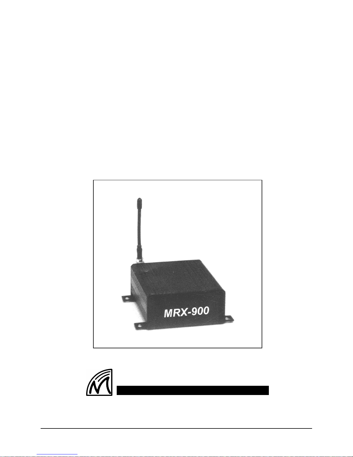
MRX-900
900 MHz Spread-Spectrum
Wireless Modem
Operating Manual
Microhard Systems Inc.
Leaders in Wireless Telecom
MRX-900 Operating Manual: Contents i
Page 2

MRX-900
900 MHz
Spread-Spectrum
Wireless Modem
This manual contains information of proprietary interest to
Microhard Systems Inc. It has been supplied in confidence to
purchasers and users of the MRX-900, and by accepting this
material the recipient agrees that the contents will not be copied
or reproduced, in whole or in part, without prior written consent
of Microhard Systems Inc.
Microhard Systems Inc. has made every effort to assure that this
document is accurate and complete. However, the company
reserves the right to make changes or enhancements to the
manual and/or the product described herein at any time and
without notice. Furthermore, Microhard Systems Inc. assumes
no liability resulting from any omissions in this document, or
out of the application or use of the device described herein.
Microhard Systems’ products are appropriate for home, office,
or industrial use, but are not authorized for utilization in
applications where failure could result in damage to property or
human injury or loss of life.
The electronic equipment described in this manual generates,
uses, and radiates radio frequency energy. Operation of this
equipment in a residential area may cause radio interference, in
which case the user, at his own expense, will be required to take
whatever measures necessary to correct the interference.
icrohard
M
Leaders in Wireless Telecom
S
#209 - 12 Manning Close N.E.
Calgary, Alberta T2E 7N6
Phone: (403) 248-0028
Fax: (403) 248-2762
www.microhardcorp.com
FCC Declaration of Conformity
This device complies with Part 15 of the FCC Rules.
Operation is subject to the following two conditions: (1) this
device may not cause harmful interference, and (2) this
device must accept any interference received including
interference that may caused undesired operation.
I
nc.ystems
© 1998 by Microhard Systems Inc., All Rights Reserved.
MRX-900 is a registered trademark of Microhard Systems Inc.
HyperTerminal is copyrighted by Hilgraeve Inc, and developed for Microsoft.
Microsoft and Windows are registered trademarks of Microsoft Corporation.
pcANYWHERE and Symantec are registered trademarks of Symantec Corp.
All other products mentioned in this document are trademarks or registered
trademarks of their respective holders.
Manual Revision 1.0, June 20, 1998.
ii MRX-900 Operating Manual
Page 3

Contents
1. Introduction
1.0 Product Overview ....................................................................................................................................... 1
1.1 Features....................................................................................................................................................... 1
1.2 About this Manual....................................................................................................................................... 2
2. Initial Installation and Setup
2.0 Unpacking and Inspection........................................................................................................................... 3
2.1 Additional Requirements ............................................................................................................................ 3
2.2 Connectors and Indicators........................................................................................................................... 4
2.3 Hardware Setup........................................................................................................................................... 4
2.4 Configuration.............................................................................................................................................. 5
2.4.1 Quick Start Approach....................................................................................................................... 5
A. Point-to-Point ............................................................................................................................. 5
B. Point-to-Multipoint..................................................................................................................... 6
3. Configuration Options
3.0 Changing Parameters in Configuration Menu............................................................................................. 7
3.1 Operating Mode.......................................................................................................................................... 7
3.2 Serial Baud Rate ......................................................................................................................................... 9
3.3 Wireless Link Rate...................................................................................................................................... 9
3.4 Network Address....................................................................................................................................... 10
3.5 Unit Address ............................................................................................................................................. 10
3.6 Hopping Pattern........................................................................................................................................ 10
3.7 Encryption Key......................................................................................................................................... 11
3.8 Output Power Level.................................................................................................................................. 11
3.9 Packet Parameters..................................................................................................................................... 12
3.10 Radio Statistics.......................................................................................................................................... 13
3.11 Slave List .................................................................................................................................................. 13
Appendices
A. MRX-900 Configuration Menu Navigation Chart................................................................ 15
B. Configuration Record............................................................................................................ 17
C. RS-232 Interface and Cables
C.0 RS-232 Line Signals ................................................................................................................................. 19
C.1 DTE-to-DCE (Straight-Through) Cables.................................................................................................. 19
C.2 Crossover / Null Modem Cables............................................................................................................... 20
C.3 Loopback Plug.......................................................................................................................................... 20
D. Surface or Wall Mounting..................................................................................................... 21
E. Troubleshooting..................................................................................................................... 23
F. Technical Specifications........................................................................................................ 25
G. Glossary................................................................................................................................. 27
MRX-900 Operating Manual: Contents iii
Page 4

ii MRX-900 Operating Manual
Page 5
1. Introduction
1.0 Product Overview
Congratulations on choosing the MRX-900 wireless modem! Your new
MRX-900 is a state-of-the-art, 900 MHz frequency-hopping spread-spectrum
communications transceiver. Equipped with the MRX-900, terminal devices
(DTEs) up to 30 km (or more)1 apart will be capable of establishing highspeed2 communications wirelessly.
Once properly installed and configured, a pair of MRX-900s provides a
practical and reliable alternative to using traditional analog phone-line
modems or “null-modem” serial cable (RS-232) connections for data
communications between terminal equipment. Moreover, wireless data
communications using the MRX-900 means you will benefit from:
n greater flexibility and freedom to relocate terminal equipment,
n reduced cabling hassles,
n eliminated requirement for access to wire-based transfer media
such as telephone lines,
n the ability to communicate through walls, floors, and many
other obstacles.
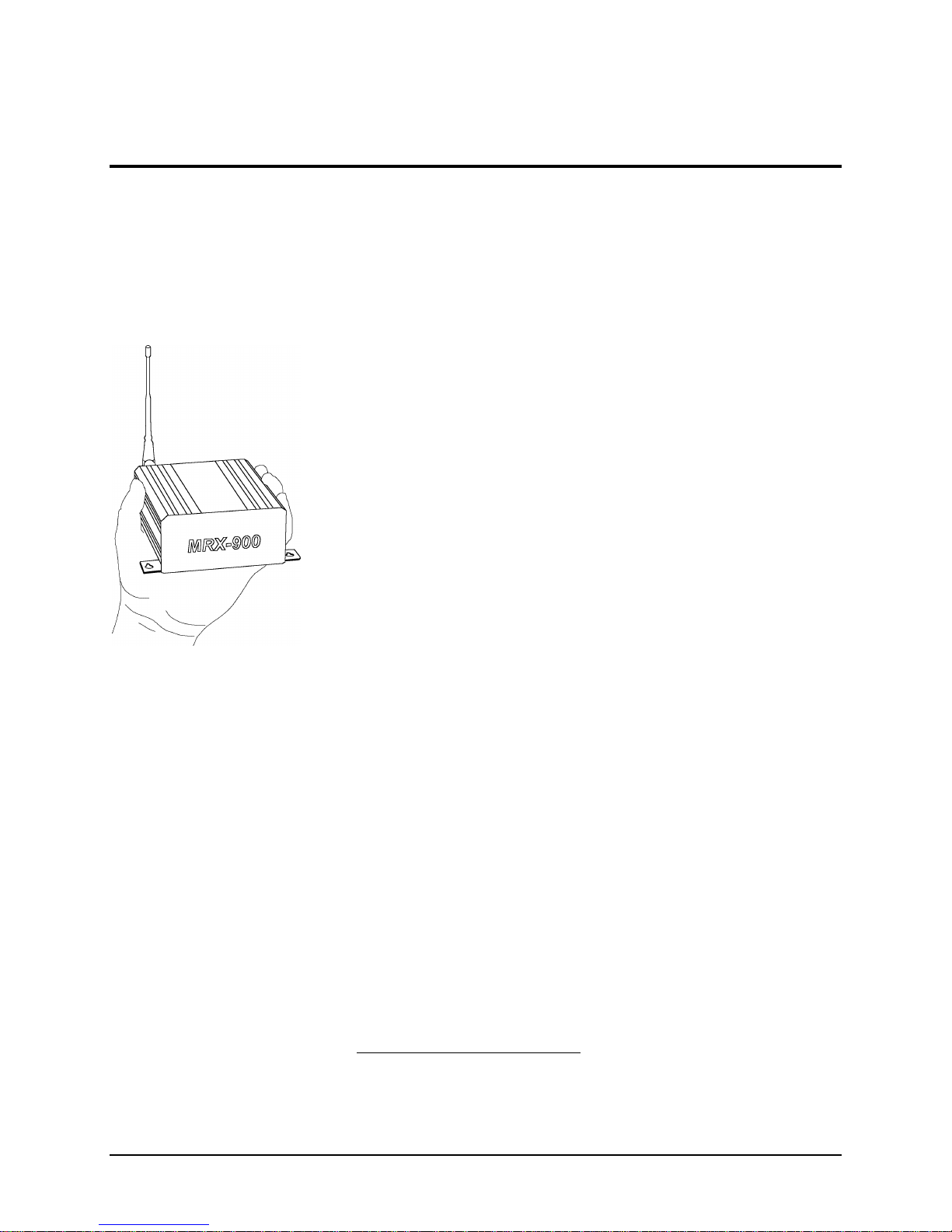
While the MRX-900 is handsomely sleek and compact in its design, it
delivers power and convenience and offers quality and dependability.
The MRX-900’s versatility makes it the ideal solution for applications
ranging from office-productivity to industrial data control and acquisition.
While a pair of MRX-900 modems can link two terminal devices (“point-topoint” operation), multiple MRX-900 units can be used together to create a
network of various topologies (“point-to-multipoint” operation). Multiple
independent networks can operate concurrently, so it is possible for unrelated
communications operations to take place in the same or a nearby area without
sacrificing privacy, functionality, or reliability.
1.1 Features
Key features of the MRX-900 include:
n transmission within a public, license-exempt band of the radio
spectrum3 – this means there are no conditions on usage of the
MRX-900, and that it can be used without restrictions or access
fees (such as those incurred by cellular airtime);
n a fully compliant RS-232 serial I/O data port with handshaking
and hardware flow control, allowing the MRX-900 to interface
with virtually any terminal device with an asynchronous RS-232
port, such as a computer;
1
Ideal conditions with clear line-of-sight communications, using high-gain antennas.
2
Up to 115,200 bits per second (bps).
3
902-928 MHz, which is license-free within North America; may need to be factory-configured
differently for some countries.
MRX-900 Operating Manual: Introduction. 1
Page 6

n twenty different user-selectable pseudo-random hopping
patterns to offer the possibility of separately operating multiple
networks while providing security, reliability and high tolerance
to interference;
n encryption key with 65536 user-selectable values to maximize
security and privacy of communications;
n built-in CRC-16 error detection and auto re-transmit to provide
100% accuracy and reliability of data;
n ease of installation and use – the MRX-900 can be used as a
drop-in replacement for most null-modem cable (DTE-to-DTE)
operations, and as a modem replacement with minimal or no
software changes.
While the typical application for the MRX-900 is to provide a mid- to longrange wireless communications link between DTEs, it can be adapted to
almost any situation where an RS-232 asynchronous serial interface is used
and data intercommunication is required.
1.2 About this Manual
This manual has been provided as a guide and reference for installing and
using MRX-900 wireless modems. The manual contains instructions,
suggestions, and information which will help you set up and achieve optimal
performance from your equipment using the MRX-900.
Although the manual is intended for all MRX-900 users from the novice to
the professional, it is recommended that new users of the MRX-900
thoroughly read Chapters 2 and 3, which describe the initial setup and
configuration of the modems. Also, it may be noteworthy to review sections
of Chapter 4 which are relevant to your application while providing helpful
hints for optimizing your MRX-900 modems. The Appendices, including the
Glossary of Terms, are provided as informational references which you may
find useful throughout the use of this manual as well as during the operation
of the wireless modem.
Throughout the manual, you will encounter not only illustrations that further
elaborate on the accompanying text, but also several symbols which you
should be attentive to:
Caution or Warning: Usually advises against some action which could
result in undesired or detrimental consequences.
Point to Remember: Highlights a key feature, point, or step which is worth
noting, Keeping these in mind will make using the MRX-900 more useful
or easier to use.
Tip: An idea or suggestion is provided to improve efficiency or to make
something more useful.
With that in mind, enjoy extending the boundaries of your communications
with the MRX-900, and please remember to send in your warranty
registration!
2 MRX-900 Operating Manual: Introduction
Page 7
2. Initial Setup and Configuration
2.0 Unpacking and Inspection
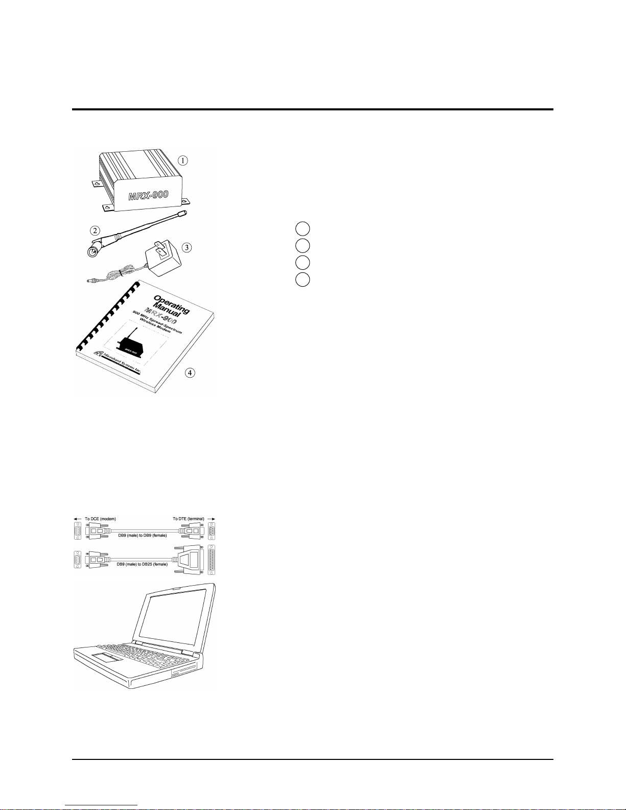
The following items should be found in the shipping carton. Inspect the
modem and accessories for damage. Report damages or shortages to the
distributor from which the unit was purchased. Keep all packing materials in
the event that transportation is required in the future.
Package contents (normal distribution):
1 MRX-900 Wireless Modem 1
2 6” Rubber Ducky Antenna 1
3 9 VDC, 1 Amp Power Adapter 1
4 Operating Manual (this document) 1
The materials you received may vary from those depicted in the figures,
which should be referred to only as a guideline.
2.1 Additional Requirements
Since the MRX-900 is a unique product in a class of its own, it will
communicate only with another MRX-900 which has been compatibly
configured. Thus, at least two MRX-900s will be required to establish a
wireless communications link. Each MRX-900 will also require access to a
120 VAC power source.
Additionally, the following requirements should be taken into consideration
when preparing to install your MRX-900 wireless modem. These represent
“typical” requirements, but due to the large variation of user needs and
applications, the items are user-supplied and are not accessories which
normally ship with the MRX-900. However, most of these are readily
available from any electronics or computer retailer, or they can be ordered
through your distributor for Microhard Systems’ products.
n Shielded “straight-through” RS-232 cable (typically DB9P-to-
DB9S or DB9P-to-DB25S) for each MRX-900 to DTE
connection*.
n Connection adapters and converters, if necessary (e.g., gender-
changers, DB9-to-DB25 adapters, etc.)
n Terminal device (e.g., PC or laptop) with functional RS-232 port
and appropriate communications (terminal emulation) software.
n Mounting hardware (screws) if surface or wall mounting is
desired (see Appendix D for mounting information)
* Note: DB9P denotes a 9-position D-sub male connector (with pins), while DB9S
denotes the mating connector of female gender (with sockets).
Although the physical space required for the MRX-900 is minimal, you
should ensure that there is sufficient room for access to the unit’s rear panel
(where connectors and indicators are located), as well as for an antenna to be
connected (typically oriented in an upright/vertical position).
MRX-900 Operating Manual: Initial Setup and Configuration. 3
Page 8
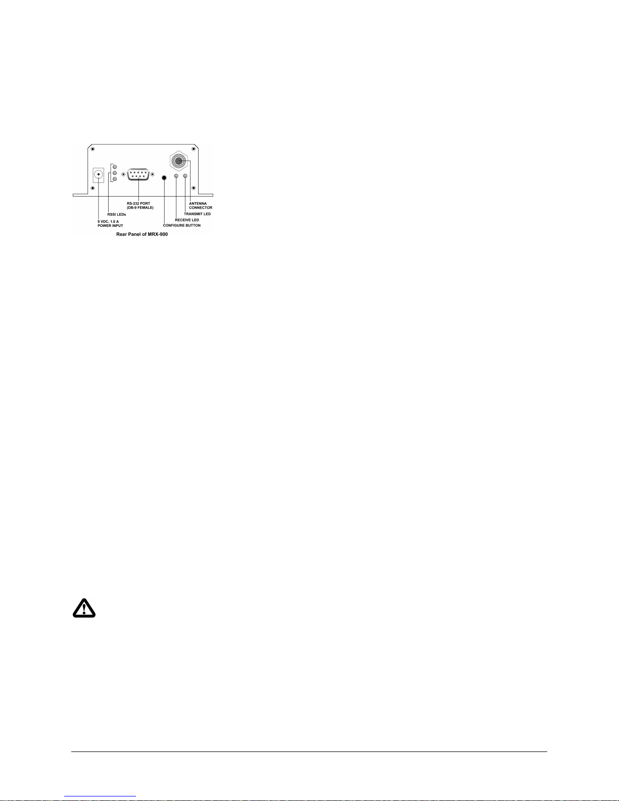
2.2 Connectors and Indicators
Locate the rear panel of the MRX-900. The interface connectors and
indicator lights are summarized below. This manual will refer to these items
in the sections that follow.
9 VDC Input - It is recommended that the provided power adapter be used to
supply power to the MRX-900 via this connector, although any
compatible DC power source which has an output of 9 volts and at least 1
amp may be used.
Receive Signal Strength Indicator (RSSI) LEDs - These LEDs show the
quality/strength of the received signal. As the signal strength increases,
the LEDs will illuminate incrementally from bottom to top.
RS-232 Data Port (DCE) - The socketed (female) D-sub connector is used to
interface the MRX-900 to a DTE device and operates at 2400 to 115,200
bps. The same port is used to configure the modem by interfacing to a
terminal (at 9600 bps). See Appendix C for details on the RS-232
interface and line signals.
Configuration Button - This button is used to configure the modem. When
depressed for about 2-3 seconds, the configuration menu will be initiated
and displayed on the connected terminal (DTE) screen. Subsequent
interaction with the modem is performed using the terminal keyboard.
Receive LED - Lights up when the modem receives data over the wireless link,
as well as during internal carrier search and synchronization operations.
Transmit LED - Lights to indicate that the modem is transmitting data wire-
lessly. This light flashes during initial startup and carrier synchronization.
Antenna Connector - Reverse-polarity TNC connector for connecting any
compatible antenna, including the provided rubber-ducky antenna.
Caution: Using any other power
supply which does not provide the
proper voltage or current could
damage the MRX-900 and void
your warranty. Doing so is at your
own risk.
2.3 Hardware Setup
Prior to setting up and configuring the MRX-900, please observe the
requirements outlined in Section 2.1. When you are ready for the initial
setup:
1. Connect the modem to a terminal or personal computer (DTE) using a
standard serial cable. Depending on the connector on your DTE device, you
will typically need a DB9-to-DB9 or DB9-to-DB25 cable (see Appendix C
for additional information). Connect the male DB9 end of the cable to the
MRX-900 data port.
2. Apply power to the MRX-900 by plugging the provided adapter into the
power input socket, and the other end into an active 120 VAC outlet. (You
will see the Receive LED illuminate to indicate that it is operating normally.)
3. On your terminal or in your terminal program (e.g. HyperTerminal in
Microsoft Windows or Procomm Plus from Datastorm Technologies), ensure
that the correct port is selected and that it has been configured for a speed of
9600 baud and a data format of 8N1 (8 bits, No parity, 1 stop bit). Although
no terminal emulation is necessary, TTY can be selected if desired.
4. You are now ready to configure the modem for operation. The following
sections will walk you through the procedure.
4 MRX-900 Operating Manual: Initial Setup and Configuration
Page 9
2.4 Configuration
Prior to establishing a wireless link, each MRX-900 that will participate in
the link must be correctly configured for compatibility and for the desired
mode of operation.
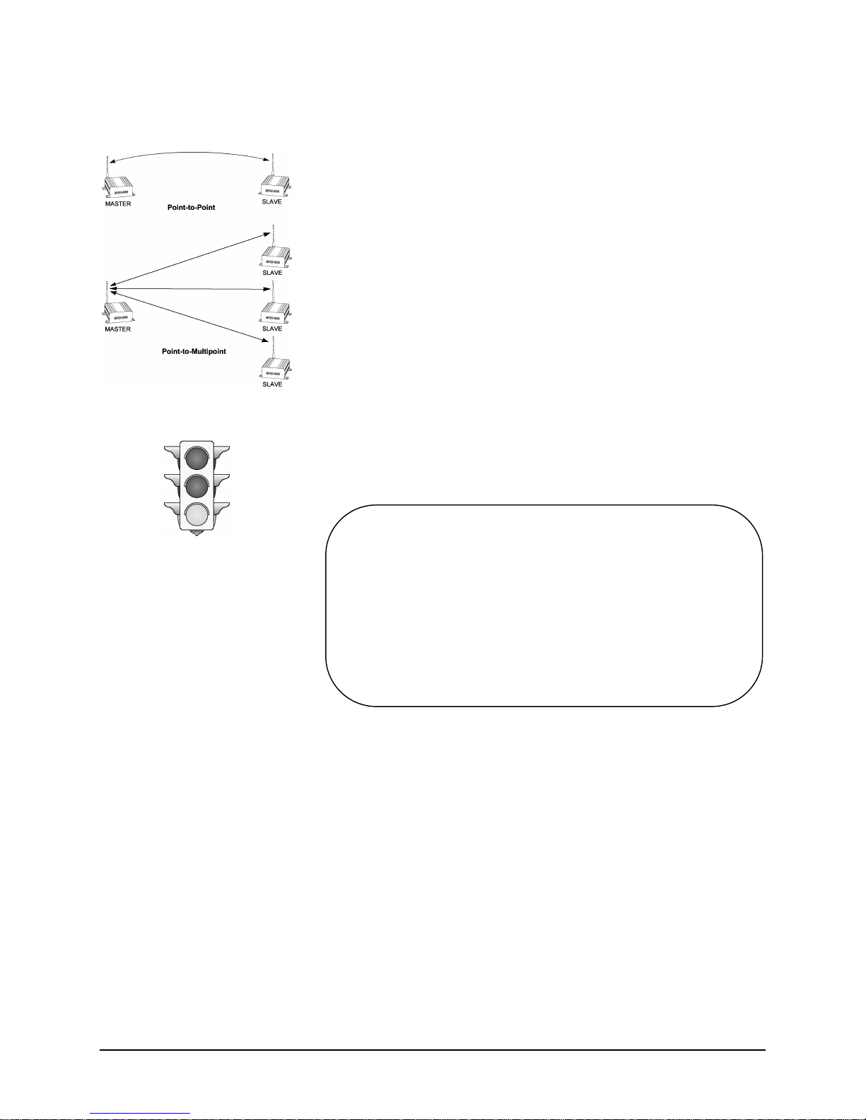
The two most common types of networks used are:
n Point-to-point: A master station communicates with a single
slave station.
n Point-to-multipoint: A master station communications with
two or more slave stations.
Within any network, the master will communicate only with slave(s) assigned
to the same network. Similarly, a slave will only communicate with the
master of the network to which it is assigned.
The quick configuration procedure is outlined below for each of these modes.
2.4.1 Quick Start Approach
Assuming your hardware has been properly setup (as outlined in Section 2.3)
for configuration, you are now ready to begin the process. Start by locating
the Configuration Button at the rear of your MRX-900 and pressing it for two
to three seconds. A menu similar to the following should appear on your
terminal screen:
Microhard Systems Inc
MRX-900 Configuration
1) Operating Mode Slave - Point to Point
2) Serial Baud Rate 115200
3) Wireless Link Rate Turbo
4) Network Address 1
5) Unit Address 1
6) Hopping Pattern A
7) Encryption Key 0
8) Output Power Level 1 mW
9) Packet Parameters
A) Radio Stats
ESC to exit
Select an Item to Configure : _
The minimum configuration requirements for point-to-point and point-tomultipoint are summarized below. These requirements will get you started
and only ensure that a link can be established, but do not necessarily provide
the best performance; optimization of the communications link is discussed
in later sections.
A. Point-to-Point
To establish a point-to-point communications link, the following requisites
must be satisfied:
n The Operating Mode for one modem must be configured as a
“Master - Point-to-Point”, and the other as a “ Slave - Point-to-
Point”.
n The Serial Baud Rate for each modem must be set to match the
baud rate of the connected equipment (DCE and DTE rates must be
equivalent).
MRX-900 Operating Manual: Initial Setup and Configuration. 5
Page 10

n The Wireless Link Rate for both modems must be the same.
n The Network Address assigned for both modems must be the
same.
n The Unit Address assigned for both modems must be the same.
n The same Hopping Pattern must be selected for both modems.
n Both modems must use the same Encryption Key.
B. Point-to-Multipoint
To establish a point-to-multipoint network, the following requisites must be
satisfied:
n The Operating Mode for one modem must be configured as a
Point-to-Multipoint Master, and the others as Point-toMultipoint Slaves.
n The Serial Baud Rate for each modem must be set to match the
baud rate of the connected equipment (DCE and DTE rates must be
equivalent).
n The Wireless Link Rate for all modems must be the same.
n The Network Address assigned to all modems must be the same.
n Each Slave must be assigned a unique Unit Address.
n The Master must have a list of all Slave Unit Numbers in its Slave
List.
n The same Hopping Pattern must be selected for all modems.
n All modems must use the same Encryption Key.
Warning: Using an antenna other
than one approved by Microhard
Systems Inc. could result in
undesired performance, and may
damage the MRX-900. Failure to
use an approved antenna may void
your warranty. It is the user’s
responsibility to ensure the
antenna has adequate lightning
protection.
Each of the parameters above are defined using the terminal to display the
menu-driven configuration screens and setting the appropriate items. Settings
are immediately stored in non-volatile memory upon selection, and are
therefore retained even after powering down. Each item and the settable
parameters within the modem configuration are described in detail in Chapter
3: Configuration Options. Once the configuration is complete, the modems
can be restored to operation mode by either pressing ESC to exit the menu
(“Running ...” should then appear), or simply by power-cycling the unit
(momentarily disrupting power to the unit, then restoring it).
2.5 Checking the Link
Once configured properly, a pair or set of communicating modems can be tested
to ensure that a link can be successfully established. Attach the provided antenna
to the antenna connector on each MRX-900 and screw the antenna in snugly.
The modems should indicate the status of the wireless link via the RSSI
LEDs on the rear panel: if the link is good, up to three LEDs should
illuminate; and if the link is absent (due to a fault at one end or another, such
as misconfiguration), the LEDs will be unlit. It is recommended that if
MRX-900s will be deployed in a field where large distances separate DTEs,
the modems be configured and tested in close proximity (e.g., in the same
room) first to ensure a good link can be established and settings are correct.
This will facilitate troubleshooting, should problems arise.
6 MRX-900 Operating Manual: Initial Setup and Configuration
Page 11

3. Configuration Options
3.0 Configuration Parameters
The MRX-900 is easily configured to meet a wide range of needs and
applications. Configuration is fully menu-driven and requires only a terminal
with a 9600 baud RS-232 port. Configuration mode is initiated by depressing
the Configuration Button on the back panel of the MRX-900 and holding it
for at least two or three seconds. The main configuration menu is then
displayed:
Microhard Systems Inc
MRX-900 Configuration
1) Operating Mode Slave - Point to Point
2) Serial Baud Rate 115200
3) Wireless Link Rate Turbo
4) Network Address 1
5) Unit Address 1
6) Hopping Pattern A
7) Encryption Key 0
8) Output Power Level 1 mW
9) Packet Parameters
A) Radio Stats
ESC to exit
Select an Item to Configure : _
In configuration mode, the
default serial rate for the
MRX-900 is 9600 baud.
Refer to Appendix A (page
15) for a menu navigation
chart to facilitate use of the
configuration menus.
Configuration options are
immediately stored in nonvolatile memory when
selected and become active
after exiting configuration or
power-cycling the unit.
Note that 9600 baud is the default rate for configuration only, and that the
actual data communications rate during operation is user-defined, with rates
from 2400 to 115,200 bps. (With reference to the serial data port, baud and
bps can correctly be used interchangeably since no modulation occurs to
increase the bit rate over the baud rate. This may not always be the case with
modulated signals transmitted between DCEs.) No terminal emulation is
required, although a “TTY” setting can be used if mode selection is required
by your communications software.
Most menu items are hot-key driven, requiring minimal keypresses to quickly
navigate and set parameters. Current parameters are indicated to the right of
each item in the main configuration menu (see above), and preceded by an
asterisk (*) for each chosen option in parameter submenus (shown on
following pages). Configuration parameters are saved in non-volatile
memory as soon as they are selected. This allows quick configuration of the
modem and reactivation in operation mode by either pressing ESC on the
terminal from the main configuration menu, or simply power-cycling the unit
(momentarily disconnecting power to the MRX-900).
3.1 Operating Mode
The Operating Mode partly defines the “personality” of the MRX-900.
When item 1 is chosen from the configuration menu, the following options
are available:
MRX-900 Operating Manual: Configuration Options 7
Page 12

Operating Mode
* 1) Master - Point to Point
2) Slave - Point to Point
3) Master - Point to Multipoint
4) Slave - Point to Multipoint
5) Repeater
ESC to exit
Select Operating Mode : _
Each unit must be either a
Master, Slave, or Repeater.
Only one Master can exist
for each network.
Each unit should be configured as a Master or Slave, except when it is used
as a Repeater. The user should decide, prior to deployment, whether a pointto-point or point-to-multipoint network is appropriate for the application, and
how each unit will be assigned to terminals.
1) Master - Point to Point One unit in a point-to-point link
should be set as the Master, obligating the other modem to be used as a
Slave. During operation, it makes little difference which end is which,
especially if data is generally transmitted unidirectionally at any given
moment. In cases where both DTEs will generally transmit large amounts of
data simultaneously, the Master should be assigned to the terminal whose
transmit priority is higher. When both terminals have data to send, more
bandwidth is dynamically allocated to the Master; otherwise, the transmitting
end, whichever it is at the time, is given the full bandwidth.
2) Slave - Point to Point The terminal in a point-to-point
network which is not set as the Master, is obligated to be the Slave. The
Slave will communicate with the Master, either directly or through a repeater,
whose network address, unit address, and hopping pattern matches its own.
3) Master - Point to Multipoint In a point-to-multipoint
network, one unit should be set as the Master, obligating all other modems to
be Slaves. The Master designation is generally given to the station which
functions as a hub for all remote nodes, and it is the Master station’s
responsibility to control communications with Slaves. When this mode is
selected, an additional option, “B) Slave List”, will appear in the main
menu. The Master, using its Slave List, will communicate with Slaves on the
same network in a round-robin fashion. Setting up the Slave List will be
described in more detail later.
8 MRX-900 Operating Manual: Configuration Options
4) Slave - Point to Multipoint Several Slaves exist in a point-
to-multipoint network, all of which communicate with the common Master.
Each slave may communicate with the Master directly, through a repeater of
its own, or via a common repeater. Slaves cannot directly communicate with
other Slaves.
5) Repeater The Repeater mode is chosen when the unit will function as
neither a Master nor a Slave, but as an intermediary in a Master-Slave(s)
relationship. The Repeater is useful when the direct Master-to-Slave
transmission distance exceeds the maximum range or transmission is
hindered due to environmental or geographical conditions. A repeater can
serve one or more slaves much like the point-to-multipoint master. When this
mode is selected, an additional option, “B) Slave List”, will appear in
the main menu. Setting up the Slave List will be described in more detail
later.
Page 13
3.2 Serial Baud Rate
The Serial Baud Rate is the speed that the DTE communications port will be
set at during normal operation. This rate has no bearing on the serial rate
during configuration, which is always performed at 9600 baud. The possible
parameters after selecting item 2 from the configuration menu are:
Serial Baud Rate
* 1) 115200
2) 57600
3) 38400
4) 28800
5) 19200
6) 14400
7) 9600
8) 7200
9) 4800
A) 3600
B) 2400
ESC to exit
Select Serial Baud Rate : _
It is generally advisable to choose the highest rate that your terminal
equipment will handle to maximize performance, unless a limitation on the
available bandwidth is desired. If the DTE is a personal computer, the port
can usually be used reliably at 115200. It is important that the rate specified
in the MRX-900 configuration matches that of the DTE to which it is
connected, or the DTE-DCE communication will fail.
3.3 Wireless Link Rate
The Wireless Link Rate is the speed and optimization method for which
modems will communicate over the RF link. The possible settings are:
Wireless Link Rate
* 1) Turbo
2) Fast
3) Normal
ESC to exit
Select Wireless Link Rate : _
Depending on the application requirements, each mode will provide different
throughputs and performance optimizations as follows:
Mode
Turbo 115.2 kbps Optimized for Speed
Fast 57.6 kbps Optimized for Distance and Speed
Normal 28.8 kbps Optimized for Distance
Generally, the lowest rate which provides sufficient bandwidth should be
selected. For example, if DTEs are set to communicate at 19.2 kbps, then the
wireless rate can be set to Normal (with the added advantage of slightly
greater range). If DTEs will typically require nearly 115.2 kbps of sustained
bandwidth, then the wireless rate should be set to Turbo (setting it lower
would “bottleneck” data transmissions in the wireless link). Note that there is
a slight compromise between speed performance and range.
Expected Performance
(Maximum Throughput)
Primary Optimization
MRX-900 Operating Manual: Configuration Options 9
Page 14

Select a Network Address
and assign it to all units
which will be included in the
network.
3.4 Network Address
The Network Address defines the membership to which individual units can
be a part of. By establishing a network under a common Network Address,
the network can be isolated from any other concurrently operating network
using the same hardware. As well, the Network Address provides a measure
of privacy and security. Only those units which are members of the network
will participate in the communications interchange. Valid values for the
Network Address range from 0 to 65535, inclusive. Choosing the option
from the main menu (option 4) will yield something like the following, after
which up to five digits can be entered, followed by Enter or Return:
Network Address = 39513
ESC to exit
Set Network Address : _
To enhance privacy and reliability of communications where multiple
networks may operate concurrently in close proximity, it is suggested that an
atypical value be chosen – perhaps something meaningful yet not easily
selected by chance or coincidence.
3.5 Unit Address
Use the same Unit Address
on all units for point-to-point
mode. In multipoint mode,
set all slaves to a unique
Unit Address.
Ensure that all units within a
network use the same
hopping pattern, and that
multiple concurrent networks
each have different hopping
patterns.
In point-to-point operation, the Unit Address on all units (Master, Slave, and
Repeater, if applicable) must be the same. In a multipoint system, the Unit
Address uniquely identifies each Slave from the others. This parameter,
whose value can range from 0 to 65535 inclusive, is set in parallel with the
Slave List (described later), so the Unit Address for each slave should be
noted and subsequently added to the Slave List. The parameter is set by
selecting item 5 in the configuration menu, and entering up to five digits
followed by the Enter or Return key:
Unit Address = 23
ESC to exit
Set Unit Address : _
Remember that each Slave should have a Unit Address which is unique from
any other Slave in the network.
3.6 Hopping Pattern
Since the MRX-900 is a frequency-hopping modem, the carrier frequency
changes periodically according one of twenty pseudo-random patterns,
selected by defining the Hopping Pattern. When this option (#6) is chosen
from the configuration menu, something resembling the following appears:
Hopping Pattern = A
ESC to exit
Set Hopping Pattern [A..T] :
10 MRX-900 Operating Manual: Configuration Options
A letter from A to T, inclusive, can be used to select the pattern. It is
important that all units which will participate in a network use the same
hopping pattern, or the communication link will fail.
Page 15

3.7 Encryption Key
The Encryption Key provides a measure of security and privacy of
communications by rendering the transmitted data useless without the correct
key on the receiver. By selecting option 7 from the configuration menu, you
are prompted to enter a key (valid values range from 0 to 65535), followed
by Return or Enter:
Encryption Key = 6109
ESC to exit
Set Encryption Key : _
Keep in mind that all units within the network must use the same key for
communications to succeed.
3.8 Output Power Level
The Output Power Level determines at what power the MRX-900 transmits.
The super-sensitive MRX-900 can operate with very low power levels, so it
is recommended that the lowest power necessary is used; using excessive
power contributes to unnecessary “RF polution”. To set the power level,
select option 8 from the configuration menu and select one of the following:
Power Output Level
1) 1 mW
2) 10 mW
3) 100 mW
* 4) 1000 mW
5) Adaptive
ESC to exit
Select Power Output Level : _
Test the communications
link using a low power level
and work upward. Avoid
using a higher power than
necessary since performance
may actually degrade.
Warning: When transmitting
at the full power of 1W, FCC
regulations prohibit using an
antenna with a gain greater
than 6 dBi (6 dB above
isotropic gain).
Ideally, you should test the communications performance between units
starting from a low power level and working upward until the RSSI is
sufficiently high and a reliable link is established. Although the conditions
will vary widely between applications, typical uses for each setting are
described below:
Power Use
1 mW
For in-building use, typically provides a link up to 300 feet on the
same floor or up/down a level. Outdoors, distances of 10 km can be
achieved if high-gain (directional) antennas are placed high above
ground level and are in direct line-of-sight.
10 mW
100 mW
1000 mW
(1 W)
200-500 ft indoors, 8-15 km outdoors.
400-800 ft indoors, 15-25 km outdoors.
Typically provides communications up to a distance of 1000 feet or
more in-building on the same floor or up/down a few levels,
depending on building construction (wood, concrete, steel, etc.). In
ideal outdoor conditions, up to 30 km or more can be achieved.
Note that only an antenna with a gain of no more 6 dBi may be used.
Any higher is a violation of FCC rules.
Adaptive
Used in noisy environments where interference may vary. Power
may change over time. Note that only an antenna with a gain of no
more 6 dBi may be used. Any higher is a violation of FCC rules.
MRX-900 Operating Manual: Configuration Options 11
Page 16

3.9 Packet Parameters
Packet Parameters define the characteristics of the internal packets or frames
which are transmitted. The settings should be set only by an expert since
adequate care must be taken to maintain reliability and optimum
performance. .The parameters which can be set are displayed under option 9
in the main menu:
Packet Parameters
1) Minimum Size 0
2) Maximum Size 255
3) Retry Limit 255
4) CRC/Retransmit Enabled
ESC to exit
Select a Parameter to Configure : _
In an ideal situation where
the communications link
performs well and there is no
interfering “noise” that can
cause errors, set the
Minimum Size to 0 and
Maximum Size to 255.
1) Minimum Size This setting has a range of 0 to 255, and defines the
number of bytes to accumulate from the DTE before transmitting a packet.
Setting this value to 0 ensures that all characters sent by the DTE are
immediately transmitted. The value may not exceed the maximum packet
size.
2) Maximum Size This setting has a range of 1 to 255, and defines the
maximum number of bytes from the DTE which should be encapsulated in a
packet. This value should be greater than the minimum packet size, but not
smaller than is necessary for reliable communications. If the wireless link is
consistently good and solid, a maximum size of 255 is recommended.
However, if the link is poor (e.g., experiencing excessive interference) and
data is frequently retransmitted, the maximum packet size should be reduced.
This decreases the probability of errors within packets, and reduces the
amount of traffic in the event that retransmissions are required. Since a
smaller packet size results in a proportionally higher overhead and lower
overall throughput on a good connection, this should only be reduced if many
errors are being detected by CRC (see Radio Statistics option of
configuration).
3) Retry Limit This determines the number of attempts that will be
made to retransmit data which failed the CRC checksum. Once the limit is
reached, the modem will give up and discard the data. If the wireless
connection is poor and data often needs to be retransmitted, a modem could
be “tied up” trying to retransmit, thus holding up pending data. (XXX)
4) CRC/Retransmit This parameter is either Enabled or Disabled, and
determines whether the MRX-900 will handle error-checking and manage
retransmissions (to guarantee accuracy of data, possibly at the cost of
throughput), or whether these functions will be handled by the software on
each DTE. When this parameter is selected, the following submenu is
displayed:
12 MRX-900 Operating Manual: Configuration Options
CRC/Retransmit
* 1) Enabled
2) Disabled
ESC to exit
Select CRC usage : _
Page 17
3.10 Radio Statistics
This option (selection A) displays a list of performance statistics for the unit
since it was powered up. Note that this information is only available if
configuration is not initiated immediately after a power-up cycle; loss of
power will reset the statistics. The information report resembles the
following:
Radio Statistics
Number of header packets transmitted: 4920
Number of data packets transmitted: 5933
Number of errors detected by CRC: 1
Average RSSI: 64
Press any key
Number of header packets transmitted: Gives an indication
of the number of header packets transmitted since power-up and is used for
troubleshooting. This value increases from 0 to 65535, at which point it
“wraps around” to 0 again.
Number of data packets transmitted: Gives an indication of
the number of data packets transmitted since power-up and is used for
troubleshooting. This value increases from 0 to 65535, at which point it
“wraps around” to 0 again.
Number of errors detected by CRC: Each packet transmitted
by the MRX-900 includes a checksum against which the data on the receiving
end is checked. If the CRC values do not match, an error event is added to
the total error count since power-up. This statistic is only available if CRC
error detection is enabled, and gives a measure of the quality of the wireless
connection. Note that when errors are detected, the sending modem
retransmits the packet so errors are never observed at the DTE.
Average RSSI: Indicates the average strength of the RF connection for
the period since power-up. Values may have values in the following ranges:
RSSI Meaning
< 50 Marginal link, may yield poor performance
50-60 Satisfactory link
60-70 Good link, should generally provide adequate performance
70-80 Strong link, typically very good performance
> 80 Very strong link
3.11 Slave List
This option (B) only appears if the unit has been set up as a Point-toMultipoint Master or as a Repeater. When selected, the following submenu
will become available:
Slave List
1) Add Slave
2) Delete Slave
3) Show List
4) Clear List
ESC to exit
Select an operation : _
MRX-900 Operating Manual: Configuration Options 13
Page 18

1) Add Slave Selecting this option subsequently prompts for a slave
address: “Add Slave Address : _“. Enter a value from 0 to 65535
which corresponds to a Slave Unit Address, followed by Enter/Return. Use
care to ensure the value is correctly entered since there is no way for the
Master or Repeater to validate the entry. Up to 255 Slaves may be added to
the Slave List.
2) Delete Slave This operation is used to reverse the action of option
1, removing a previously-entered slave from the Slave List. When selected,
the prompt, “Delete Slave Address : _” appears. A value from 0
to 65535 should be entered, followed by Enter/Return.
3) Show List This option displays the current list of slaves, each
separated by a comma, similar to the following:
Select an operation : 3
List of Slaves
00001, 00002, 00020, 00032, 00050
4) Clear List This option removes all slaves from the Slave List, and
should be used with caution. It is an alternative to repetitively using option 2
for each Slave in the list. When selected, you are prompted with the
following: “Clear the entire slave list? (Y) _”. Pressing
“Y” will clear the entire list, while pressing any other key will exit and abort
the command.
14 MRX-900 Operating Manual: Configuration Options
Page 19

A. The Configuration Menus
1) Master - Point to Point
Delete
The following chart provides an “at-a-glance” overview of the menus available when configuring the MRX-900, as
well as the valid parameters for each item.
List
Slave
Stats
Radio
Packet
Parameters
Retry
Timeout
List
Clear
List
Show
(2) (3)(1) (4)
Slave
Level
Power Output
1) 1mW
2) 10 mW
3) 100 mW
4) 1000 mW (1W)
(7) (8) (9) (A) (B)
Key
0-655351) Turbo
Encryption
(6)
Configuration Main Menu
A-T
Pattern
Hopping
Unit
0-65535
Address
Interval
Timeout
(2) (3)(1) (4)
Size
Maximum
MRX-900 Configuration Quick-Reference
Wireless
(2)(1) (3) (5)(4)
Serial Baud
Operating
MRX-900 Operating Manual: The Configuration Menus 15
2) Fast
Link Rate
Rate
1) 115200
2) 57600
Mode
2) Slave - Point to Point
3) Normal
3) 38400
4) 28800
5) 19200
6) 14400
7) 9600
8) 7200
9) 4800
A) 3600
B) 2400
3) Master - Point to Multipoint
4) Slave - Pont to Multipoint
5) Repeater
Page 20

16 MRX-900 Operating Manual
Page 21

B. Configuration Record
The following tables are provided as a convenient way to record the configuration of your MRX-900s for future
reference. You may wish to copy or adapt it for your use.
MRX-900 Record of Configuration
o Point-to-Point Operation
Unit Mode Unit
Address
Master
S/N:
_________
Slave
S/N:
_________
Repeater
S/N:
_________
Output Power
Level
o 1 mW
o 10 mW
o 100 mW
o 1000 mW (1W)
o 1 mW
o 10 mW
o 100 mW
o 1000 mW (1W)
o 1 mW
o 10 mW
o 100 mW
o 1000 mW (1W)
Serial Baud Rate Wireless
o 115200 o 57600
o 38400 o 28800
o 19200 o 14400
o 9600 o 7200
o 4800 o 3600
o 2400
o 115200 o 57600
o 38400 o 28800
o 19200 o 14400
o 9600 o 7200
o 4800 o 3600
o 2400
o Turbo
o Fast
o Normal
Link
Network Address
(0 - 65535)
Hopping Pattern
(A - T)
Encryption Key
(0 - 65535)
MRX-900 Operating Manual: Configuration Record 17
Page 22

o Point-to-Multipoint Operation
Unit Mode Address Output Power
Master
S/N:
_________
Slave
S/N:
_________
Slave
S/N:
_________
Slave
S/N:
_________
Slave
S/N:
_________
Slave
S/N:
_________
Slave
S/N:
_________
Repeater
S/N:
_________
Repeater
S/N:
_________
Repeater
S/N:
_________
Slave List: o 1 mW
Unique
Unit Address
(0-65535):
Unique
Unit Address
(0-65535):
Unique
Unit Address
(0-65535):
Unique
Unit Address
(0-65535):
Unique
Unit Address
(0-65535):
Unique
Unit Address
(0-65535):
Slave List: o 1 mW
Slave List: o 1 mW
Slave List: o 1 mW
Level
o 10 mW
o 100 mW
o 1000 mW (1W)
o 1 mW
o 10 mW
o 100 mW
o 1000 mW (1W)
o 1 mW
o 10 mW
o 100 mW
o 1000 mW (1W)
o 1 mW
o 10 mW
o 100 mW
o 1000 mW (1W)
o 1 mW
o 10 mW
o 100 mW
o 1000 mW (1W)
o 1 mW
o 10 mW
o 100 mW
o 1000 mW (1W)
o 1 mW
o 10 mW
o 100 mW
o 1000 mW (1W)
o 10 mW
o 100 mW
o 1000 mW (1W)
o 10 mW
o 100 mW
o 1000 mW (1W)
o 10 mW
o 100 mW
o 1000 mW (1W)
Serial Baud Rate Wireless
o 115200 o 57600
o 38400 o 28800
o 19200 o 14400
o 9600 o 7200
o 4800 o 3600
o 2400
o 115200 o 57600
o 38400 o 28800
o 19200 o 14400
o 9600 o 7200
o 4800 o 3600
o 2400
o 115200 o 57600
o 38400 o 28800
o 19200 o 14400
o 9600 o 7200
o 4800 o 3600
o 2400
o 115200 o 57600
o 38400 o 28800
o 19200 o 14400
o 9600 o 7200
o 4800 o 3600
o 2400
o 115200 o 57600
o 38400 o 28800
o 19200 o 14400
o 9600 o 7200
o 4800 o 3600
o 2400
o 115200 o 57600
o 38400 o 28800
o 19200 o 14400
o 9600 o 7200
o 4800 o 3600
o 2400
o 115200 o 57600
o 38400 o 28800
o 19200 o 14400
o 9600 o 7200
o 4800 o 3600
o 2400
o Turbo
o Fast
o Normal
Link
Network Address
(0 - 65535)
Hopping Pattern
(A - T)
Encryption Key
(0 - 65535)
18 MRX-900 Operating Manual: Configuration Record
Page 23

C. RS-232 Interface and Cables
C.0 RS-232 Line Signals
The MRX-900 uses a 9-pin D-sub connector for asynchronous serial I/O.
The pin assignments conform to standard RS-232 signals, so a common serial
cable can be used for interfacing the MRX-900 to most DTE devices.
“Straight-through”
DB9-to-DB9
RS-232 Cable
Modem
(DCE)
9-pin male Signal
1
2
3
4
5
6
7
8
←
←
←
DCD
RX
TX
DTR
SG
DSR
RTS
CTS
9 (n/c) (n/c) 9
“Straight-through”
DB9-to-DB25
RS-232 Cable
Modem
(DCE)
9-pin male Signal
1
2
3
←
4
←
5
6
7
←
8
9 (n/c)
Arrows denote the direction that
signals are asserted (e.g., DCD
originates at the DCE and tells the
DTE that a carrier is present).
DCD
RX
TX
DTR
SG
DSR
RTS
CTS
Terminal
→
→
→
→
→
Terminal
→
→
→
→
→
(DTE)
9-pin
1
2
3
4
5
6
7
8
(DTE)
25-pin
8
3
2
20
7
6
4
5
Line signals in the RS-232 interface are described below:
DCD Data Carrier Detect - When set high, DCD informs the DTE that a
communications link has been established with another MRX-900.
RX Receive Data - Signals transferred from the MRX-900 are received by the
DTE via RX.
TX Transmit Data - Signals are transmitted from the DTE via TX to the
MRX-900
DTR Data Terminal Ready - Raised to an active level by the DTE to inform the
modem that it is alive and ready for communications.
SG Signal Ground - Provides a ground reference for all signals transmitted by
both DTE and DCE.
DSR Data Set Ready - Set high by the modem (DCE, or “data set” as it was
formerly called) to inform the DTE that it is alive and ready for
communications. DSR is the modem’s equivalent of the DTR signal.
RTS Request to Send - A “handshaking” signal which is asserted by the DTE when
it is ready to transmit data. (Typically, the DCE responds by activating CTS.)
Essentially, RTS is the DTE’s way of saying, “I am ready to send data
whenever you are.”
CTS Clear to Send - A “handshaking” signal set active by the DCE when it has
enabled communications and transmission from the DTE can commence.
CTS is usually asserted after the DCE has detected a RTS signal from the
DTE. It is the modem’s way of saying, “Go ahead, I am ready for your data.”
Notes: It is typical to refer to RX and TX from the perspective of the DTE. This should be
kept in mind when looking at signals relative to the modem (DCE); the modem
transmits data on the RX line, and receives on TX.
“DCE” and “modem” are often synonymous since a modem is typically a DCE device.
“DTE” is, in the most common application, is a device such as a computer.
C.1 DTE-to-DCE (Straight-Through) Cables
Due to the variety of cabling requirements by each user of the MRX-900,
interface cables required for DTE-to-DCE connection are user-supplied
items. Unless the RS-232 port or connector on the DTE deviates from the
common pin assignments, it is recommended that pre-fabricated shielded
cables (and interface adapters, if necessary) be purchased for your application
to ensure optimal performance and reliability. In cases where an RJ-45 DTE
termination is required, the cable will need to be designed according to the
DTE’s RJ-45 pinout; this 8-position connector has no standard assignment of
signals and varies greatly between devices and manufacturers.
If cables must be fabricated, the wiring diagrams provided should be used.
For best results, it is recommended that cables be no longer than necessary to
interface the DTE and DCE (up to about 25 feet).
MRX-900 Operating Manual: RS-232 Interface and Cables 19
Page 24

“Crossover” / “Null”
1,6
4
2
3
3
2
4
1,6
5
5
7
8
8
79(n/c)
(n/c)
9
1,6
20
2
2
3
3
4
6,8
5
7
7
5
8
49(n/c)
(n/c)
9
1
1
2
3
3
2
4
5
5
4
6,8
20
7
7
20
6,8
1
(n/c)2345
(n/c)6789
(n/c)
DB9-to-DB9
RS-232 Cable
9-pin 9-pin
“Crossover” / “Null”
DB9-to-DB25
RS-232 Cable
9-pin 25-pin
“Crossover” / “Null”
DB25-to-DB25
RS-232 Cable
25-pin 25-pin
C.2 Crossover / Null Modem Cables
Typically, establishing a DTE-to-DCE connection is achieved using a
straight-through cable as described earlier. In some instances, generally
when a direct DTE-to-DTE or DCE-to-DCE connection is desired, a
crossover cable (also known as rollover, null-modem, or modem-eliminator
cable) is used. Using a straight-through cable will not work
In a DTE-to-DTE connection, the crossover cable essentially functions by
deceiving each DTE into “thinking” that it is connected to a modem.
Similarly, a DCE connected to a DCE “believes” it is connected to a DTE.
The data transmission is handled such that transmitted data (TX) from one
device is driven to the receive data line (RX) of the other. RTS is associated
with CTS. Since a DCE in a typical DTE-to-DCE connection usually must
indicate its own online status (via DSR) as well as its connection to another
DCE (via DCD), these are relayed together as a ready-state indicator from the
DTE via DTR.
Wiring diagrams for the most common cables of this type are provided for
your reference.
C.3 Loopback Plug
Occasionally, you may wish to perform diagnostic or benchmark tests on the
data transmission between two MRX-900s. A common test is the loopback,
whereby an MRX-900, connected to a DTE, communicates with another
MRX-900, whose serial port has been fitted with a DCE loopback plug. By
so doing, all data sent by the DTE should be wirelessly transmitted to the
remote MRX-900, which echoes back the data to the originator, namely the
DTE. Essentially the same data is transmitted twice: once to the remote
modem, and the second time as it is re-transmitted back from the remote
modem. Such tests are useful for testing the performance of the wireless link,
including throughput, bit error rate, packet loss, and a number of other
measures.
The wiring for a basic 9-pin DCE loopback plug is provided, which can be
constructed simply by tying together pins 2 and 3, as well as 7 and 8, on a
male DB9 connector.
Note that in all cases, the DSR and
DCD lines are tied together (lines 1
and 6 for DB9; 6 and 8 for DB25).
DCE DB9 Loopback Plug
9-pin male
connector
20 MRX-900 Operating Manual: RS-232 Interface and Cables
Testing that a DTE serial port is functional is often achieved easily by using a
DTE loopback plug, which can be constructed similarly to the DCE loopback
plug for a 9-pin connector. The gender is often different (use a female
connector for use on a common PC), but the same pins are tied together: 2
with 3, and 7 with 8. Additionally, pins 4 and 6 should be tied together. (For
a 25-pin DTE loopback plug, connect pins 2 with 3, 4 with 5, and 6 with 20.)
Page 25

D. Surface or Wall Mounting
1.85”
0.25”
3.57”
Drill holes for mounting by
0.15”0.32”
The drill template and dimensional figure below has been provided to facilitate placement in case you wish to mount your
MRX-900. Make a copy of the template at 100% scale and drill through the paper at each of the cross-hairs. Screw heads
should be no larger than 5/16” diameter, with outer screw shaft of no more than about 1/8”. If mounted with the rubber footprint
on bottom of unit, about 1/4” clearance should be left between surface and bottom of screw head; otherwise, unit can be mounted
flush with surface. Ensure that there is adequate clearance around unit, including room for cables and antenna.
ANT.
SERIAL
using this template.
Place template on wall
or surface and drill holes
at each “+”, using a 1/16”
bit for wood.
4.22”
MRX-900 Operating Manual: Surface or Wall Mounting 21
Page 26

22 MRX-900 Operating Manual
Page 27

E. Troubleshooting
Here are solutions to some of the common problems and symptoms that may be experienced.
————————————
Problem: I am trying to set up the MRX-900 but I cannot get the configuration menu to appear.
Solutions: 1. Make sure you are depressing the Configuration Button for at least 2 or 3 seconds. The
Configuration Menu, by design, only shows up after the button has been held briefly to prevent
unintentional triggering.
2. Check that the power adapter is snugly inserted into the power input jack, and that the AC-outlet is
live. You can verify that the MRX-900 is operational and that it is receiving power by the
continuous illumination of the receive LED.
3. Ensure that your RS-232 cable is the correct type – that it is a straight-through rather than a crossover
or null-modem cable, and that it is the correct cable for your terminal. Also ensure that the mating
connectors are seated properly.
4. Verify that you are using the correct data port and that it is configured properly (this check may be
aided by use of a DTE-loopback plug, as explained in section C.3). Ensure that the software has the
correct communications settings for configuration: 9600 bps, 8 bits, no parity, 1 stop bit (8N1). If
the serial communications between the MRX-900 and your terminal is working correctly, an
initialization message should appear each time you power up the unit.
————————————
Problem: I have configured my MRX-900s, but I cannot achieve a communications connection. The RSSI LEDs
are unlit.
Solutions: 1. Ensure that the Wireless Link Rate, Network Address, and Hopping Pattern are the same for all units.
If using the modems in multipoint operation, ensure that each Slave has a unique Unit Address and
they are included in the Slave List of Repeaters (if applicable) and of the Master. In point-to-point
mode, ensure the Unit Address on both Master and Slave are the same. Once these settings are
correct, the RSSI LEDs should illuminate when communicating units are powered up.
2. The power level is too high or too low for the current arrangement of MRX-900s. First, ensure that
antennas are properly and snugly connected. If the units are in very close proximity (within several
feet) and the power level is too high, they will be saturated and may not operate efficiently.
Conversely, if the modems are far away from each other or there are many obstacles between them, a
higher level may be required for the modems to pick up each other’s signal.
————————————
Problem: I have configured my MRX-900s, but I cannot achieve a communications connection. The RSSI LEDs
are lit.
Solutions: 1. Verify that the serial baud rate between each MRX-900 and its connecting DTE are the same.
2. Isolate the problem by directly connecting the DTEs using a crossover cable and setting the port
speeds on both ends the same. If this fails, then the problem is most likely attributable to the
DTE/software application, and use of the MRX-900 in this circumstance will also fail. If the hard
wire connection is successful, then the problem may be a cabling issue. Ensure that all cables are
straight-through RS-232 cables and that they are connected properly to all devices.
————————————
Problem: I have the serial data ports on both my DTEs and MRX-900s set the same, but I cannot achieve a
throughput near serial rate I’ve set up.
Solutions: 1. Verify that the Wireless Link Rate on all modems are set to a rate which provides a wireless link
higher than the serial links, since a lower wireless rate will “bottleneck” the communications link.
MRX-900 Operating Manual: Troubleshooting 23
Page 28

2. If you are using an MRX-900 as a Repeater, it will cut the effective throughput roughly in half
because of its “store and forward” nature; the repeater spends half of its time receiving data and the
other half transmitting the received data.
3. Although some high speed rates are achieved under ideal conditions, various factors may reduce the
effective speed. This includes external RF (radio frequency) interference from sources such as
cellular telephones and base stations. When the airwaves are “noisy”, errors can be introduced into
the data stream which force the modems to retransmit (if CRC-16 error detection is turned on),
consequently compromising effective throughput. Possible solutions include use of high-gain
(directional) antennas or relocation of antennas if possible (higher, and possibly a few feet laterally).
————————————
Problem: I seem to keep losing characters and/or received data is not the same as transmitted data over my
MRX-900s
Solutions: 1. By enabling CRC-16 error detection, the MRX-900s will automatically detect lost or corrupted data
and will resend packets to ensure accuracy. Check to see that this option is enabled (recommended)
and see if the situation improves.
2. If CRC-16 error detection is enabled and this problem is occurring, it is likely due to the link
between the MRX-900 and the DTE device, or the DTE device itself. Possible causes of this
include:
a) unshielded and/or too long a serial cable - try replacing the cable with one that is shorter, and
ensure it is shielded, particularly if the environment in which the equipment resides is subject to
electromagnetic interference.
b) absence of a 16550 UART on the DTE serial port - if the equipment being used is older, it may
have an 8250 or other UART which does not provide adequate buffering capabilities, especially
at rates higher than 9600 baud. Try replacing the serial interface driver chip or serial card if
possible and high-speed communications is necessary. Otherwise, a lower serial baud rate (on
both the modem and DTE) may help cure the problem.
c) if operating in a multi-tasking environment, the processor may not be fast enough to handle
multiple processes or threads while keeping up with the flow of serial data - if possible, reduce
the number of concurrently-running processes, or retry the operation in a single-task environment.
Alternatively, try lowering the serial baud rate (modem and DTE) to a speed that the DTE can
keep up with.
————————————
24 MRX-900 Operating Manual: Troubleshooting
Page 29

F. Technical Specifications
Electrical/Physical
Data Interface Asynchronous RS-232, 9-pin female D-sub
Signals Sig. Gnd, TX, RX, DCD, DSR, DTR, RTS, CTS
Data Rate
Communications Range
Power Requirements 9.0 VDC, 1.0 Amp
Power Consumption 600 mA at 1 W transmit, 200 mA receive
Operating Frequency 902 - 928 MHz
System Gain 135 dB
Sensitivity -105 dBm
Output Power 1mW, 10mW, 100mW, 1W (user-selectable or adaptive)
Spreading Code Frequency Hopping
Hopping Patterns 20 pseudo-random, user-selectable
Error Detection CRC-16 with auto re-transmit
1
2,400 - 115,200 bps, uncompressed half-duplex,
30 kilometers or more
Enclosure material Milled aluminum, raven-black powder coat finish
Dimensions (WxDxH) Encl: 3.72” x 4.25” x 1.72” (94.5 mm x 108.0 mm x 43.7 mm)
With extrusions (mounting legs, rear connectors):
4.72” x 5.25” x 1.72” (119.9 mm x 133.4 mm x 43.7 mm)
Weight 450 grams (with included antenna)
Operating Environment Temperature: -30 to +60°C
Humidity: 5 to 95%, non-condensing
Storage Temperature -40 to 90°C
1. Clear line-of-sight, elevated high-gain antennas.
MRX-900 Operating Manual: Troubleshooting 25
Page 30

26 MRX-900 Operating Manual
Page 31

G. Glossary
Terminology Used in the MRX-900 Operating Manual
Asynchronous communications A method of
telecommunications in which units of single bytes
of data are sent separately and at an arbitrary time
(not periodically or referenced to a clock). Bytes
are “padded” with start and stop bits to distinguish
each as a unit for the receiving end, which need
not be synchronized with the sending terminal.
Attenuation The loss of signal power through
equipment, lines/cables, or other transmission
devices. Measured in decibels (dB).
Bandwidth The information-carrying capacity of a
data transmission medium or device, usually
expressed in bits/second (bps).
Baud Unit of signaling speed equivalent to the
number of discrete conditions or events per
second. If each signal event represents only one
bit condition, then baud rate equals bits per
second (bps) – this is generally true of the serial
data port, so baud and bps have been used
interchangeably in this manual when referring to
the serial port; this is not always the case during
the DCE-to-DCE communications, where a
number of modulation techniques are used to
increase the bps rate over the baud rate.
Bit The smallest unit of information in a binary
system, represented by either a 1 or 0.
Abbreviated “b”.
Bits per second (b/s or bps) A measure of data
transmission rate in serial communications. Also
see baud.
Byte A group of bits, generally 8 bits in length. A
byte typically represents a character of data.
Abbreviated “B”.
Characters per second (cps) A measure of data
transmission rate for common exchanges of data.
A character is usually represented by 10 bits: an 8bit byte plus two additional bits for marking the
start and stop. Thus, in most cases (but not
always), cps is related to bits per second (bps) by
a 1:10 ratio.
CRC (Cyclic Redundancy Check) An error-detection
scheme for transmitted data. Performed by using
a polynomial algorithm on data, and appending a
checksum to the end of the packet. At the
receiving end, a similar algorithm is performed
and checked against the transmitted checksum.
Crossover cable (Also known as rollover, null-
modem, or modem-eliminator cable) A cable
which allows direct DTE-to-DTE connection
without intermediate DCEs typically used to
bridge the two communicating devices. Can also
be used to make cabled DCE-to-DCE connections.
The name is derived from “crossing” or “rolling”
several lines, including the TX and RX lines so
that transmitted data from one DTE is received on
the RX pin of the other DTE and vice-versa.
Data Communications Equipment (DCE, also
referred to as Data Circuit-Terminating
Equipment, Data Set) A device which facilitates a
communications connection between Data
Terminal Equipment (DTEs). Often, two or more
compatible DCE devices are used to “bridge”
DTEs which need to exchange data. A DCE
performs signal encoding, decoding, and
conversion of data sent/received by the DTE, and
transmits/receives data with another DCE.
Common example is a modem.
Data Terminal Equipment (DTE) An end-
device which sends/receives data to/from a DCE,
often providing a user-interface for information
exchange. Common examples are computers,
terminals, and printers.
dBm Stands for “Decibels referenced to one
milliwatt (1 mW)”. A standard unit of power
level commonly used in RF and communications
work. n dBm is equal to 10
0dBm = 1mW, -10dBm = 0.1mW, -20dBm =
0.01mW, etc.
DCE See Data Communications Equipment.
DTE See Data Terminal Equipment.
Flow Control A method of moderating the
transmission of data so that all devices within the
communications link (DTEs and DCEs) transmit
and receive only as much data as they can handle
at once. This prevents devices from sending data
which cannot be received at the other end due to
conditions such as a full buffer or hardware not in
a ready state. This is ideally handled by hardware
(n/10)
milliwatt, so
MRX-900 Operating Manual: Glossary 27
Page 32

using flow-control and handshaking signals, but
can be controlled also by software using X-ON/XOFF (transmitter on/off) commands.
Frequency-hopping A type of spread spectrum
communication whereby the carrier frequency
used between transmitter and receiver changes
repeatedly in a synchronized fashion according to
a specified algorithm or table. This minimizes
unauthorized jamming (interference) and
interception of telecommunications.
Full-duplex Where data can be transmitted,
simultaneously and independently, bidirectionally.
Half duplex Exists when the communications
medium supports bi-directional transmission, but
data can only travel in one direction at the same
time.
Handshaking A flow-control procedure for
establishing data communications whereby
devices indicate that data is to be sent and await
appropriate signals that allow them to proceed.
Line-of-sight Condition in which a transmitted
signal can reach its destination by travelling a
straight path, without being absorbed and/or
bounced by objects in its path.
Master The station which controls and/or polls one
or more slave stations in a point-to-point or pointto-multipoint network. Often functions as a server
or hub for the network.
Non-volatile memory Memory which retains
information which is written to it.
Null modem cable See Crossover cable.
Point-to-point A simple communications network
in which only two DTEs are participants.
Point-to-multipoint A communications network
in which a master DTE communicates with two or
more slave DTEs.
Repeater A device which automatically amplifies
or restores signals to compensate for distortion
and/or attenuation prior to retransmission. A
repeater is typically used to extend the distance
for which data can be reliably transmitted using a
particular medium or communications device.
RS-232 (Recommended Standard 232; more
accurately, RS-232C or EIA/TIA-232E) Defined
by the EIA, a widely known standard electrical
and physical interface for linking DCEs and DTEs
for serial data communications. Traditionally
specifies a 25-pin D-sub connector, although
many newer devices use a compact 9-pin
connector with only the essential signaling lines
used in asynchronous serial communications.
Lines have two possible states: “high” (on, active,
asserted, carrying +3 to +25 V) or “low” (off,
inactive, disasserted, carrying -3 to -25 V).
RTU (Remote Terminal Unit) A common term
describing a DTE device which is part of a widearea network. Often a RTU performs data I/O and
transmits the data to a centralized station.
Serial communications A common mode of
data transmission whereby character bits are sent
sequentially, one at a time, using the same
signaling line. Contrast with parallel
communications where all bits of a byte are
transmitted at once, usually requiring a signal line
for each bit.
Shielded cable Interface medium which is
internally shrouded by a protective sheath to
minimize external electromagnetic interference
(“noise”).
Slave A station which is controlled and/or polled by
the master station for communications. Typically
represents one end of a point-to-point connection,
or one of the terminal nodes in a point-tomultipoint network. Often a RTU is linked by a
slave DCE.
Spread spectrum A method of transmitting a
signal over a wider bandwidth (using several
frequencies) than the minimum necessary for the
originally narrowband signal. A number of
techniques are used to achieve spread spectrum
telecommunications, including frequency hopping.
Spread spectrum provides the possibility of
sharing the same band amongst many users while
increasing the tolerance to interference and noise,
and enhancing privacy of communications.
Throughput A measure of the rate of data trans-
mission passing through a data communication
system, often expressed as bits or characters per
second (bps or cps).
28 MRX-900 Operating Manual: Glossary
 Loading...