

Page 1
Operating Manual
IPn4Gii / IPn3Gii
IPn4Gii 4G/LTE Dual Ethernet/Serial/USB Gateway
IPn3Gii 3G/HSPA+ Dual Ethernet/Serial/USB Gateway
Document: IPn3Gii+IPn4Gii Operating Manual.v1.3.pdf
FW: v1.2.0 Build 1038
May 2015
150 Country Hills Landing NW
Calgary, Alberta
Canada T3K 5P3
Phone: (403) 248-0028
Fax: (403) 248-2762
www.microhardcorp.com
Page 2

Important User Information
Warranty
Microhard Systems Inc. warrants that each product will be free of defects in material and workmanship for a
period of one (1) year for its products. The warranty commences on the date the product is shipped by Micro-
hard Systems Inc. Microhard Systems Inc.’s sole liability and responsibility under this warranty is to repair or
replace any product which is returned to it by the Buyer and which Microhard Systems Inc. determines does
not conform to the warranty. Product returned to Microhard Systems Inc. for warranty service will be shipped
to Microhard Systems Inc. at Buyer’s expense and will be returned to Buyer at Microhard Systems Inc.’s ex-
pense. In no event shall Microhard Systems Inc. be responsible under this warranty for any defect which is
caused by negligence, misuse or mistreatment of a product or for any unit which has been altered or modified
in any way. The warranty of replacement shall terminate with the warranty of the product.
Warranty Disclaims
Microhard Systems Inc. makes no warranties of any nature of kind, expressed or implied, with respect to the
hardware, software, and/or products and hereby disclaims any and all such warranties, including but not limited to warranty of non-infringement, implied warranties of merchantability for a particular purpose, any interruption or loss of the hardware, software, and/or product, any delay in providing the hardware, software, and/
or product or correcting any defect in the hardware, software, and/or product, or any other warranty. The Purchaser represents and warrants that Microhard Systems Inc. has not made any such warranties to the Purchaser or its agents MICROHARD SYSTEMS INC. EXPRESS WARRANTY TO BUYER CONSTITUTES MICROHARD
SYSTEMS INC. SOLE LIABILITY AND THE BUYER’S SOLE REMEDIES. EXCEPT AS THUS PROVIDED, MICROHARD
SYSTEMS INC. DISCLAIMS ALL WARRANTIES, EXPRESS OR IMPLIED, INCLUDING ANY WARRANTY OF MERCHANTABILITY OR FITNESS FOR A PARTICULAR PROMISE.
MICROHARD SYSTEMS INC. PRODUCTS ARE NOT DESIGNED OR INTENDED TO BE USED IN
ANY LIFE SUPPORT RELATED DEVICE OR SYSTEM RELATED FUNCTIONS NOR AS PART OF
ANY OTHER CRITICAL SYSTEM AND ARE GRANTED NO FUNCTIONAL WARRANTY.
Indemnification
The Purchaser shall indemnify Microhard Systems Inc. and its respective directors, officers, employees, successors and assigns including any subsidiaries, related corporations, or affiliates, shall be released and discharged from any and all manner of action, causes of action, liability, losses, damages, suits, dues, sums of
money, expenses (including legal fees), general damages, special damages, including without limitation,
claims for personal injuries, death or property damage related to the products sold hereunder, costs and demands of every and any kind and nature whatsoever at law.
IN NO EVENT WILL MICROHARD SYSTEMS INC. BE LIABLE FOR ANY INDIRECT, SPECIAL, CONSEQUENTIAL,
INCIDENTAL, BUSINESS INTERRUPTION, CATASTROPHIC, PUNITIVE OR OTHER DAMAGES WHICH MAY BE
CLAIMED TO ARISE IN CONNECTION WITH THE HARDWARE, REGARDLESS OF THE LEGAL THEORY BEHIND
SUCH CLAIMS, WHETHER IN TORT, CONTRACT OR UNDER ANY APPLICABLE STATUTORY OR REGULATORY
LAWS, RULES, REGULATIONS, EXECUTIVE OR ADMINISTRATIVE ORDERS OR DECLARATIONS OR OTHERWISE,
EVEN IF MICROHARD SYSTEMS INC. HAS BEEN ADVISED OR OTHERWISE HAS KNOWLEDGE OF THE POSSIBILITY OF SUCH DAMAGES AND TAKES NO ACTION TO PREVENT OR MINIMIZE SUCH DAMAGES. IN THE EVENT
THAT REGARDLESS OF THE WARRANTY DISCLAIMERS AND HOLD HARMLESS PROVISIONS INCLUDED ABOVE
MICROHARD SYSTEMS INC. IS SOMEHOW HELD LIABLE OR RESPONSIBLE FOR ANY DAMAGE OR INJURY, MICROHARD SYSTEMS INC.'S LIABILITY FOR ANYDAMAGES SHALL NOT EXCEED THE PROFIT REALIZED BY MICROHARD SYSTEMS INC. ON THE SALE OR PROVISION OF THE HARDWARE TO THE CUSTOMER.
Proprietary Rights
The Buyer hereby acknowledges that Microhard Systems Inc. has a proprietary interest and intellectual property rights in the Hardware, Software and/or Products. The Purchaser shall not (i) remove any copyright, trade
secret, trademark or other evidence of Microhard Systems Inc.’s ownership or proprietary interest or confiden-
tiality other proprietary notices contained on, or in, the Hardware, Software or Products, (ii) reproduce or modify any Hardware, Software or Products or make any copies thereof, (iii) reverse assemble, reverse engineer or
decompile any Software or copy thereof in whole or in part, (iv) sell, transfer or otherwise make available to
others the Hardware, Software, or Products or documentation thereof or any copy thereof, except in accor-
dance with this Agreement.
© Microhard Systems Inc. 2
Page 3

Important User Information (continued)
About This Manual
It is assumed that users of the products described herein have either system integration or
design experience, as well as an understanding of the fundamentals of radio communications.
Throughout this manual you will encounter not only illustrations (that further elaborate on the
accompanying text), but also several symbols which you should be attentive to:
Caution or Warning
Usually advises against some action which could result in undesired or
detrimental consequences.
Point to Remember
Highlights a key feature, point, or step which is noteworthy. Keeping
these in mind will simplify or enhance device usage.
Tip
An idea or suggestion to improve efficiency or enhance usefulness.
Information
Information regarding a particular technology or concept.
© Microhard Systems Inc. 3
Page 4
Important User Information (continued)
Regulatory Requirements / Exigences Réglementaires
To satisfy FCC RF exposure requirements for mobile transmitting devices, a separation distance of 23cm or more should be maintained
between the antenna of this device and persons during device operation. To ensure compliance, operations at closer than this distance is not
recommended. The antenna being used for this transmitter must not be co-located in conjunction with any other antenna or transmitter.
WARNING
WARNING
WARNING
Pour satisfaire aux exigences de la FCC d'exposition RF pour les appareils mobiles de transmission, une distance de séparation de 23cm ou
plus doit être maintenue entre l'antenne de cet appareil et les personnes au cours de fonctionnement du dispositif. Pour assurer le respect,
les opérations de plus près que cette distance n'est pas recommandée. L'antenne utilisée pour ce transmetteur ne doit pas être co-localisés
en conjonction avec toute autre antenne ou transmetteur.
MAXIMUM EIRP
FCC Regulations allow up to 36dBm Effective Isotropic Radiated Power (EIRP). Therefore, the sum of the transmitted power (in dBm), the
cabling loss and the antenna gain cannot exceed 36dBm.
Réglementation de la FCC permettra à 36dBm Puissance isotrope rayonnée équivalente (EIRP). Par conséquent, la somme de la puissance
transmise (en dBm), la perte de câblage et le gain d'antenne ne peut pas dépasser 36dBm.
EQUIPMENT LABELING / ÉTIQUETAGE DE L'ÉQUIPEMENT
This device has been modularly approved. The manufacturer, product name, and FCC and Industry Canada identifiers of this product must
appear on the outside label of the end-user equipment.
Ce dispositif a été approuvé de façon modulaire. Le fabricant, le nom du produit, et la FCC et de l'Industrie du Canada identifiants de ce
produit doit figurer sur l'étiquette à l'extérieur de l'équipement de l'utilisateur final.
SAMPLE LABEL REQUIREMENT / EXIGENCE D'ÉTIQUETTE :
IPn3Gii IPn4Gii
FCCID: XPYLISAU230
IC: 8595A-LISAU230
This device complies with Part 15 of the FCC Rules.
Operation is subject to the following two conditions:
(1) this device may not cause harmful interference,
and (2) this device must accept any interference
received including interference that may cause
undesired operation.
FCCID: R17LN930
IC: 5131A-LN930
This device complies with Part 15 of the FCC Rules.
Operation is subject to the following two conditions:
(1) this device may not cause harmful interference,
and (2) this device must accept any interference
received including interference that may cause
undesired operation.
IPn4Gii - Verizon
Please Note: These are only sample labels; different products contain different identifiers. The actual identifiers should be seen on
your devices if applicable. S'il vous plaît noter: Ce sont des exemples d'étiquettes seulement; différents produits contiennent des
identifiants différents. Les identifiants réels devrait être vu sur vos périphériques le cas échéant.
© Microhard Systems Inc. 4
FCCID: R5Q-TOBYL100
IC: 8595B-TOBYL100
This device complies with Part 15 of the FCC Rules.
Operation is subject to the following two conditions:
(1) this device may not cause harmful interference,
and (2) this device must accept any interference
received including interference that may cause
undesired operation.
Page 5

CSA Class 1 Division 2 Option
CSA Class 1 Division 2 is Available Only on Specifically Marked Units
If marked this for Class 1 Division 2 – then this product is available for use in Class 1 Division 2, in the indicated Groups on the
product.
In such a case the following must be met:
The transceiver is not acceptable as a stand-alone unit for use in hazardous locations. The transceiver must be mounted within a
separate enclosure, which is suitable for the intended application. Mounting the units within an approved enclosure that is certified
for hazardous locations, or is installed within guidelines in accordance with CSA rules and local electrical and fire code, will ensure
a safe and compliant installation.
The antenna feed line; DC power cable and interface cable must be routed through conduit in accordance with the National
Electrical Code.
Do not connect or disconnect equipment unless power has been switched off or the area is known to be non-hazardous.
Installation, operation and maintenance of the transceiver should be in accordance with the transceiver’s installation manual , and
the National Electrical Code.
Tampering or replacement with non-factory components may adversely affect the safe use of the transceiver in hazardous
locations, and may void the approval.
The wall adapters supplied with your transceivers are NOT Class 1 Division 2 approved, and therefore, power must be supplied to
the units using the screw-type or locking type connectors supplied from Microhard Systems Inc. and a Class 1 Division 2 power
source within your panel.
If you are unsure as to the specific wiring and installation guidelines for Class 1 Division 2 codes, contact CSA International.
CSA Classe 1 Division 2 est disponible uniquement sur les unités particulièrement
marquées
Si marqué cette Classe 1 Division 2 - alors ce produit est disponible pour une utilisation en Classe 1 Division 2 , dans les groupes
indiqués sur le produit .
Dans un tel cas, la suivante doit être remplie:
L'émetteur-récepteur n'est pas acceptable comme une unité autonome pour une utilisation dans des endroits dangereux .
L'émetteur-récepteur doit être monté dans un boîtier séparé , qui est approprié pour l'application envisagée. Montage des unités
dans une enceinte approuvée qui est certifié pour les emplacements dangereux , ou est installé à l'intérieur des lignes directrices ,
conformément aux règles de la CSA et le code électrique local et le feu , assurera une installation sûre et conforme .
La ligne d'alimentation d'antenne , câble d'alimentation CC et le câble d'interface doivent être acheminés à travers le conduit en
conformité avec le National Electrical Code .
Ne pas connecter ou déconnecter l'équipement que l'alimentation est coupée ou que la zone est connue pour être non
dangereux .
Installation, l'exploitation et la maintenance de l'émetteur-récepteur doivent être en conformité avec le manuel d'installation de
l'émetteur-récepteur , et le National Electrical Code .
Falsification ou le remplacement des composants non - usine peut nuire à l'utilisation sécuritaire de l'émetteur-récepteur dans des
endroits dangereux , et peut annuler l'approbation .
Les adaptateurs muraux fournis avec les émetteurs-récepteurs sont PAS classe 1, division 2 ont approuvé , et par conséquent,
doit être alimenté pour les unités à l'aide des connecteurs de type vis ou verrouillage fournies par Microhard Systems Inc. et une
Division 2 source d'alimentation de classe 1 au sein de votre panneau .
Si vous n'êtes pas sûr de l' installation et de câblage des lignes directrices spécifiques pour la classe 1 Division 2 codes ,
communiquer avec la CSA International.
© Microhard Systems Inc. 5
Page 6

Revision History
Revision Description Initials Date
0.0 Preliminary. PEH Mar 2014
1.0 First Release. Based on Firmware v1.2.0 Build 1008 PEH July 2014
1.1 Updated to reflect default IP change to 192.168.168.1 for all unit
types. v1.2.0 Build 1015.
1.2 Updated to align with firmware version 1.2.0 Build 1016. Added MultiWAN, updated Carrier Dual SIM. Added TAIP, Added Websocket,
Updated I/O, Updated screenshots throughout, misc corrections.
1.21 Updated to notify users must configure firewall and/or appropriate
rules to use IP-Passthrough.
1.22 Removed AT+CMGS (Not currently Supported), Added Current Consumption.
1.3 Updated to align with firmware version v1.2.0-r1038 PEH May 2015
PEH Sept 2014
PEH Sept 2014
PEH Oct 2014
PEH Feb 2015
© Microhard Systems Inc. 6
Page 7

Table of Contents
1.0 Overview ......................................................................................................... 10
1.1 Performance Features ................................................................................................... 10
1.2 Specifications ................................................................................................................ 11
1.3 RF Performance ............................................................................................................ 13
2.0 QUICK START ................................................................................................. 15
2.1 Installing the SIM Card ................................................................ .................................. 15
2.2 Getting Started with Cellular .......................................................................................... 15
3.0 Hardware Features ......................................................................................... 19
3.1 IPnXGii ......................................................................................................................... 19
3.1.1 IPnXGii Mechanical Drawings .............................................................................. 20
3.1.2 IPnXGii Connectors & Indicators .......................................................................... 21
3.1.2.1 Front ...................................................................................................... 21
3.1.2.2 Rear ...................................................................................................... 22
4.0 Configuration.................................................................................................. 23
4.0 Web User Interface ...................................................................................................... 23
4.0.1 Logon Window ..................................................................................................... 24
4.1 System ......................................................................................................................... 25
4.1.1 Summary ............................................................................................................. 25
4.1.2 Settings ............................................................................................................... 26
Host Name .......................................................................................................... 26
Console Timeout.................................................................................................. 26
Date/Time ............................................................................................................ 27
NTP Server Settings ............................................................................................ 28
4.1.3 Services .............................................................................................................. 29
SSH ..................................................................................................................... 29
Telnet .................................................................................................................. 29
HTTP/HTTPS ...................................................................................................... 29
4.1.4 Keepalive............................................................................................................. 30
4.1.5 Maintenance ........................................................................................................ 32
Firmware Upgrade ............................................................................................... 32
Reset to Default ................................................................................................... 32
Backup & Restore Configurations ........................................................................ 33
4.1.6 Reboot ................................................................................................................. 34
4.2 Network ....................................................................................................................... 35
4.2.1 Summary ............................................................................................................. 35
4.2.2 LAN ..................................................................................................................... 36
4.2.3 WAN .................................................................................................................... 39
4.2.4 DHCP (MAC Binding) .......................................................................................... 41
4.2.5 DDNS .................................................................................................................. 42
4.2.6 Routes ................................................................................................................. 43
4.2.6 Ports (Switch) ...................................................................................................... 44
4.2.7 Device List ........................................................................................................... 44
© Microhard Systems Inc. 7
Page 8

Table of Contents
4.3 Carrier .......................................................................................................................... 45
4.3.1 Status .................................................................................................................. 45
4.3.2 Settings ............................................................................................................... 46
Dual Cards Management ..................................................................................... 47
4.3.3 SMS .................................................................................................................... 51
4.3.4 SMS Config ......................................................................................................... 52
4.3.5 Data Usage ......................................................................................................... 55
4.4 Firewall ....................................................................................................................... 58
4.4.1 Summary ............................................................................................................. 58
4.4.2 General ............................................................................................................... 59
4.4.3 Port Forwarding ................................................................................................... 61
4.4.4 MAC-IP List ......................................................................................................... 63
4.4.5 Rules ................................................................ ................................................... 65
4.4.6 Firewall Default .................................................................................................... 67
4.5 VPN ............................................................................................................................ 68
4.5.1 Summary ............................................................................................................. 68
4.5.2 Gateway to Gateway............................................................................................ 69
4.5.3 Client to Gateway (L2TP Client) ........................................................................... 74
4.5.4 GRE .................................................................................................................... 76
4.5.5 L2TP Users ......................................................................................................... 79
4.5.6 Certificates .......................................................................................................... 80
4.6 MultiWAN ..................................................................................................................... 81
4.6.1 Status .................................................................................................................. 81
4.6.2 Settings ............................................................................................................... 82
4.7 Serial ............................................................................................................................ 84
4.7.1 Summary ............................................................................................................. 84
4.7.2 RS232/Console/RS485 Settings .......................................................................... 85
Data Baud Rate ................................................................................................... 86
IP Protocol Config ................................................................................................ 89
TCP Client ...................................................................................................... 89
TCP Server ..................................................................................................... 89
TCP Client/Server ........................................................................................... 90
UDP Point-to-Point ................................ .......................................................... 90
UDP Point-to-Multipoint (P) ............................................................................. 90
UDP Point-to-Multipoint (MP) .......................................................................... 91
UDP Multipoint-to-Multipoint ............................................................................ 91
SMTP Client .................................................................................................... 92
PPP ................................................................................................................ 92
GPS Transparent Mode .................................................................................. 93
4.8 USB .............................................................................................................................. 94
4.8.1 Summary ............................................................................................................. 94
4.8.2 Serial ................................................................ ................................................... 95
4.8.3 NDIS ................................................................................................................... 96
4.9 I/O ................................................................................................................................ 97
4.9.1 Summary ............................................................................................................. 97
© Microhard Systems Inc. 8
Page 9

Table of Contents
4.10 GPS ................................................................ .............................................................. 99
4.10.1 Location ............................................................................................................. 99
4.10.2 Settings ................................................................ .............................................. 100
4.10.3 Report ................................................................................................................ 101
4.10.4 GPSGate ............................................................................................................ 103
4.10.5Recorder ............................................................................................................. 106
4.10.6 Load Record ....................................................................................................... 107
4.10.7 TAIP ................................................................................................................... 110
4.11 Applications ................................................................................................................ 112
4.11.1 Modbus .............................................................................................................. 112
4.11.1.1 TCP Modbus ........................................................................................ 112
4.11.1.2 Serial (COM) Modbus........................................................................... 114
4.11.1.3 Modbus Data Map ................................................................................ 115
4.11.2 Netflow Report ................................................................................................... 116
4.11.3 Local Monitor ..................................................................................................... 118
4.11.4 Event Report ...................................................................................................... 119
4.11.4.1 Configuration ....................................................................................... 119
4.11.4.2 Message Structure ............................................................................... 120
4.11.4.2 Message Payload................................................................................. 120
4.11.5 Websocket ......................................................................................................... 122
4.11.6 Diagnostics ........................................................................................................ 124
Network Ping...................................................................................................... 124
Network Trace Route ......................................................................................... 124
4.12 Admin .......................................................................................................................... 125
4.12.1 Users ................................................................................................................. 125
4.12.2 Authentication (RADIUS) .................................................................................... 127
4.12.3 NMS .................................................................................................................. 128
4.12.4 SNMP ................................................................................................................ 132
4.12.5 Discovery ........................................................................................................... 135
4.12.6 Power Saving Modes ......................................................................................... 136
4.12.7 Logout ................................................................................................................ 137
5.0 AT Command Line Interface........................................................................... 138
5.1 AT Command Overview .............................................................................................. 138
5.1.1 Serial Port ................................ ................................................................ .......... 138
5.1.2 Telnet................................................................................................................. 139
5.2 AT Command Syntax .................................................................................................. 140
5.3 Supported AT Commands .......................................................................................... 141
Appendices .......................................................................................................... 174
Appendix A: Serial Interface .................................................................................................. 174
Appendix B: IP-Passthrough Example ................................................................................... 175
Appendix C: Port Forwarding Example .................................................................................. 177
Appendix D: VPN (Site to Site) Example ............................................................................... 179
Appendix E: Firewall Rules Example ..................................................................................... 181
Appendix F: Troubleshooting................................................................................................. 183
© Microhard Systems Inc. 9
Page 10

1.0 Overview
The IPn4Gii & IPn3Gii products are high-performance Cellular Dual Ethernet/Serial/USB
Gateways, equipped with dual RJ45 Ethernet Ports, dual SIM capability, 8x Programmable
Analog I/O, Optional Standalone GPS, and up to three serial communication ports. One each
of RS232, RS485 and a RS232 Console port, which can be used as an additional data port.
The IPnXGii utilizes the cellular infrastructure to provide network access to wired devices anywhere cellular coverage is supported by a cellular carrier. The IPn3Gii supports up to 21Mbps
downloads, when connected to a HSPA+ enabled carrier, or global fallback to 3G/Edge networks for areas without HSPA+. The IPn4Gii supports 4G/LTE connections with blazing fast
speeds.
Providing reliable Cellular Ethernet bridge functionality as well gateway service for most
equipment types which employ an RS232, RS422, or RS485 interface, the IPnXGii can be
used in a limitless types of applications such as:
High-speed backbone
IP video surveillance
Voice over IP (VoIP)
Facilitating internetwork
wireless communications
Legacy network/device
migration
SCADA (PLC’s, Modbus,
Hart)
1.1 Performance Features
Key performance features of the IPnXGii include:
Fast, reliable connection speeds to 4G, 3G, LTE, and HSPA Networks (varies by
model)
8x Programmable Analog/Digital Inputs OR up to 8 Digital Outputs
DMZ and Port Forwarding
Dual 10/100 Ethernet Ports (WAN/LAN)
Standalone GPS (TCP Server/UDP/SMTP Reporting)
User interface via local console, telnet, web browser
Compatibility with virtually all PLCs, RTUs, and serial devices through either
RS232, RS422, or RS485 interfaces.
Local & remote wireless firmware upgradable
User configurable Firewall with IP/MAC ACL
IP/Sec secure VPN and GRE Tunneling
Industrial Temperature Rating (-40oC to +85oC)
© Microhard Systems Inc. 10
Page 11

1.0 Overview
1.2 Specifications
IPn3Gii
IPn3Gii Supported Bands: UMTS/HSPA FDD Bands [MHz] - Six band
Band I (2100MHz), Band II (1900MHz), Band IV (1700MHz), Band V
(850MHz), Band VI (800MHz), Band VIII (900Hz)
3GPP Release 7
5.76 Mb/s uplink, 21.1 Mb/s downlink
or 5.76 Mb/s uplink, 7.2 Mb/s downlink
IPn3Gii Data Features: HSDPA cat 14, up to 21.1 Mb/s DL
GPRS multi-slot class 125, coding scheme CS1-CS4, up to 85.6 kb/s DL/UL
EDGE multi-slot class 125, coding scheme MCS1-MCS9, up to 236.8 kb/s DL/UL
CSD GSM max 9.6 kb/s
UMTS max 64 kb/s
IPn3Gii TX Power: WCDMA/HSDPA/HSUPA Power Class
· Power Class 3 (24 dBm) for WCDMA/HSDPA/HSUPA mode
GSM/GPRS Power Class
· Power Class 4 (33 dBm) for GSM/E-GSM bands
· Power Class 1 (30 dBm) for DCS/PCS bands
EDGE Power Class
· Power Class E2 (27 dBm) for GSM/E-GSM bands
· Power Class E2 (26 dBm) for DCS/PCS bands
IPn4Gii
IPn4Gii Supported Bands: LTE FDD (Bands 1-5,7,8,13,17,18,19,20)
UMTS | DC-HSPA+ (Bands 1,2,4,5,8)
GSM | GPRS | EDGE (Bands 2,3,5,8)
3GPP Protocol Stack Release 9
IPn4Gii Data Features: LTE: DL 100 Mbps, UL 50 Mbps
HSPA+: DL 42 Mbps, UL 5.7 Mbps
HSPA+: DL 21 Mbps, UL 5.7 Mbps
WCDMA: DL/UL 384 kbps
EDGE Class 33: DL/UL 236.8 kbps
GPRS Class 33: DL/UL 85.6kbps
General
Serial Interface: RS232, RS485, RS422
Serial Baud Rate: 300bps to 921kbps
USB: USB 2.0
USB Console Port
USB to Serial Data Routing
USB to Ethernet Data Routing (NDIS)
USB OTG (Host)
Current Consumption:
(@12VDC)
Model
IPn3Gii 130mA 140mA 215mA
IPn4Gii 130mA 145mA 250mA
AVG Serial
Data
AVG Ethernet
Data
TX Max. Peak
© Microhard Systems Inc. 11
Page 12

1.0 Overview
General Specifications (Continued)
Ethernet: 2 x 10/100 BaseT, Auto - MDI/X, IEEE 802.3
I/O: 8x Programmable Analog/Digital Inputs or up to 8x Digital Outputs
60mA current sink on open drain
SIM Card: Dual: 1.8 / 3.0V
PPP Characteristics: Dial on Demand/Idle Time
Network Protocols: TCP, UDP, TCP/IP, TFTP, ARP, ICMP, DHCP, HTTP, HTTPS*, SSH*, SNMP,
FTP, DNS, Serial over IP, QoS
Management: Local Serial Console, Telnet, WebUI, SNMP, FTP &
Wireless Upgrade, RADIUS authentication, IPsec VLAN
Diagnostics: Temperature, RSSI, remote diagnostics
Input Voltage: 7-30 VDC
Power over Ethernet: Passive PoE on Ethernet Port (WAN)
GPS: Sensitivity: - Autonomous acquisition: -145 dBm
- Tracking Sensitivity: -158 dBm (50% valid fixes)
Position Accuracy: - Tracking L1, CA code
- 12 Channels
- Max. update rate 1 Hz
Error calculated location less than 11.6 meters 67% of the time, and
less than 24.2 meters 95% of the time.
Environmental
Operation Temperature: -40
Humidity: 5% to 95% non-condensing
o
F(-40oC) to 185oF(85oC)
Mechanical
Dimensions: 2.21” (56mm) X 3.85” (97mm) X 1.46” (37mm)
Weight: Approx. 245 grams
Connectors: Antenna(s): CELL, DIV, GPS: SMA Female
ANT3: RP-SMA Female
Data, etc: Data: DE-9 Female (Front RS232)
Ethernet : 2x RJ-45
GPS Antenna Requirements:
- Frequency Range: 1575.42 MHz (GPS L1 Band)
- Bandwidth: +/- 2 MHz
- Total NF < 2.5dB
- Impedance 50ohm
- Amplification (Gain applied to RF connector): 19dB to 23dB
- Supply voltage 1.5V to 3.05V
- Current consumption - Typical 20mA (100mA max)
- Cellular Power Antenna Rejection + Isolation:
- 824 - 915 MHz > 10dB
- 1710 - 1785 MHz > 19dB
- 1850 - 1980 MHz > 23dB
© Microhard Systems Inc. 12
Page 13

1.0 Overview
1.3 IPn3Gii RF Performance
Frequency Range Min. (MHz) Max. (MHz) Remarks
GSM 850
E-GSM 900
DCS 1800
PCS1900
UMTS 800 (band VI)
UMTS 850 (band V)
UMTS 900 (band VIII)
UMTS 1700 (band VIII)
UMTS 1900 (band II)
UMTS 2100 (band 1)
Uplink 824 849 Module transmit
Downlink 869 894 Module receive
Uplink 880 915 Module transmit
Downlink 925 960 Module receive
Uplink 1710 1785 Module transmit
Downlink 1805 1880 Module receive
Uplink 1850 1910 Module transmit
Downlink 1930 1990 Module receive
Uplink 830 840 Module transmit
Downlink 875 885 Module receive
Uplink 824 849 Module transmit
Downlink 869 894 Module receive
Uplink 880 915 Module transmit
Downlink 925 960 Module receive
Uplink 1710 1755 Module transmit
Downlink 2110 2155 Module receive
Uplink 1850 1910 Module transmit
Downlink 1930 1990 Module receive
Uplink 1920 1980 Module transmit
Downlink 2110 2170 Module receive
Table 1-1: IPn3Gii Operating RF Frequency Bands
Receiver Input Sensitivity Min. (dBm) Typ. (dBm) Max. (dBm) Remarks
GSM 850 / E-GSM 900 -102.0 -110.0 Downlink RF level @ BER Class II < 2.4%
DCS 1800 / PCS 1900 -102.0 -109.0 Downlink RF level @ BER Class II < 2.4%
UMTS 800 (band VI) -106.7 -111.0 Downlink RF level for RMC @ BER < 0.1%
UMTS 850 (band V) -104.7 -112.0 Downlink RF level for RMC @ BER < 0.1%
UMTS 900 (band VIII) -103.7 -111.0 Downlink RF level for RMC @ BER < 0.1%
UMTS 1700 (band VIII) -106.7 -111.0 Downlink RF level for RMC @ BER < 0.1%
UMTS 1900 (band II) -104.7 -111.0 Downlink RF level for RMC @ BER < 0.1%
UMTS 2100 (band 1) -106.7 -111.0 Downlink RF level for RMC @ BER < 0.1%
Condition: 50 Ω source
Table 1-2: IPn3Gii Receiver sensitivity performance
© Microhard Systems Inc. 13
Page 14

1.0 Overview
1.3 IPn3Gii
Maximum Output
Power
GSM 850 / E-GSM 900
DCS 1800 / PCS 1900
UMTS 800 (band VI) 23.0 Uplink continuous RF power for RMS at maximum power
UMTS 850 (band V) 23.0 Uplink continuous RF power for RMS at maximum power
UMTS 900 (band VIII) 23.0 Uplink continuous RF power for RMS at maximum power
UMTS 1700 (band VIII) 23.0 Uplink continuous RF power for RMS at maximum power
UMTS 1900 (band II) 23.0 Uplink continuous RF power for RMS at maximum power
UMTS 2100 (band 1) 23.0 Uplink continuous RF power for RMS at maximum power
Condition for all parameters: 50 Ω output load
Condition for GPRS/EDGE multi-slot output power: Multi-Slot Power Reduction profile 2
RF Performance (continued…)
Min.
32.5 Uplink burst RF power for GSM or GPRS 1-slot TCH at PCL 5 or Gamma 3
32.5 Uplink burst RF power for GPRS 2-slot TCH at Gamma 3
31.7 Uplink burst RF power for GPRS 3-slot TCH at Gamma 3
30.5 Uplink burst RF power for GPRS 4-slot TCH at Gamma 3
27.0 Uplink burst RF power for EDGE 8PSK 1-slot TCH at PCL 8 or Gamma 6
27.0 Uplink burst RF power for EDGE 8PSK 2-slot TCH at Gamma 6
26.2 Uplink burst RF power for EDGE 8PSK 3-slot TCH at Gamma 6
25.0 Uplink burst RF power for EDGE 8PSK 4-slot TCH at Gamma 6
29.5 Uplink burst RF power for GSM or GPRS 1-slot TCH at PCL 0 or Gamma 3
29.5 Uplink burst RF power for GPRS 2-slot TCH at Gamma 3
28.7 Uplink burst RF power for GPRS 3-slot TCH at Gamma 3
27.5 Uplink burst RF power for GPRS 4-slot TCH at Gamma 3
26.0 Uplink burst RF power for EDGE 8PSK 1-slot TCH at PCL 2 or Gamma 5
26.0 Uplink burst RF power for EDGE 8PSK 2-slot TCH at Gamma 5
25.2 Uplink burst RF power for EDGE 8PSK 3-slot TCH at Gamma 5
24.0 Uplink burst RF power for EDGE 8PSK 4-slot TCH at Gamma 5
Typ.
(dBm)
Table 1-3: IPn3Gii Transmitter maximum output power
Max. Remarks
© Microhard Systems Inc. 14
Page 15
2.0 Quick Start
This QUICK START guide will walk you through the setup and process required to access the
WebUI configuration window and to establish a basic wireless connection to your carrier.
Note that the units arrive from the factory with the Local Network setting configured as
‘Static’ (IP Address 192.168.168.1, Subnet Mask 255.255.255.0, and Gateway
192.168.168.1), in DHCP server mode. (This is for the LAN Ethernet Adapter on the back of
the IPnXGii unit.
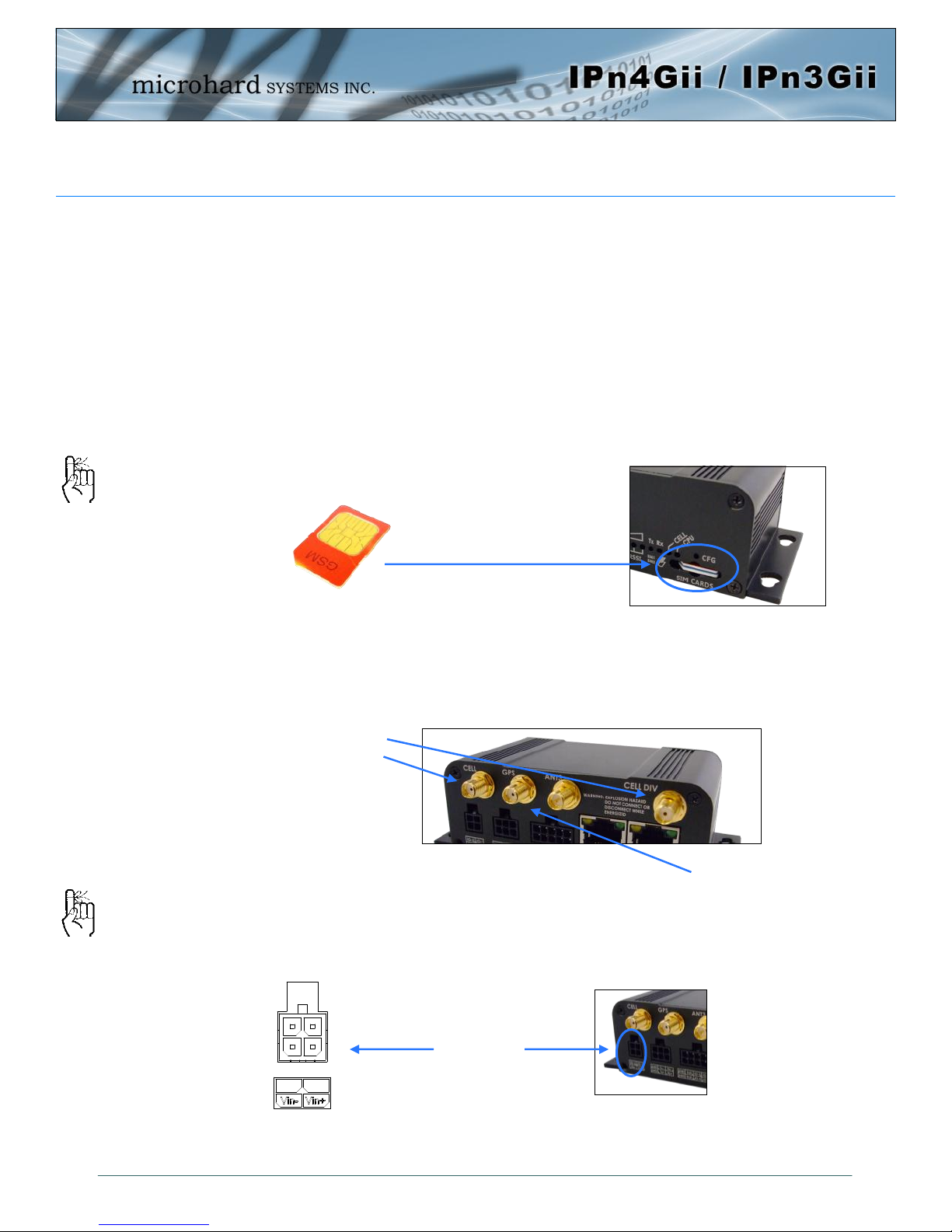
2.1 Installing the SIM Card
Before the IPnXGii can be used on a cellular network a valid SIM Card for your Wireless
Carrier must be installed. Insert the SIM Card into the slot as shown, the top SIM slot is
for SIM1:
To reset to factory
defaults, press and hold
the CFG button for 8
seconds with the IPnXGii
powered up. The LED’s
will flash quickly and the
IP4G will reboot with
factory defaults.
Use the MHS-supplied
power adapter or an
equivalent power source.
The unit can also be powered
via PoE using a MHS PoE
injector.
2.2 Getting Started with Cellular
Connect the Antenna’s to the applicable ANTENNA jack’s of the IPnXGii.
Connect the power connector to the power adapter and apply power to the unit, the CPU
LED will flash during boot-up, once on solid, proceed to the next step.
SIM Card Slot
Cellular
Antenna’s
GPS Antenna
7-30VDC
© Microhard Systems Inc. 15
Page 16
2.0 Quick Start
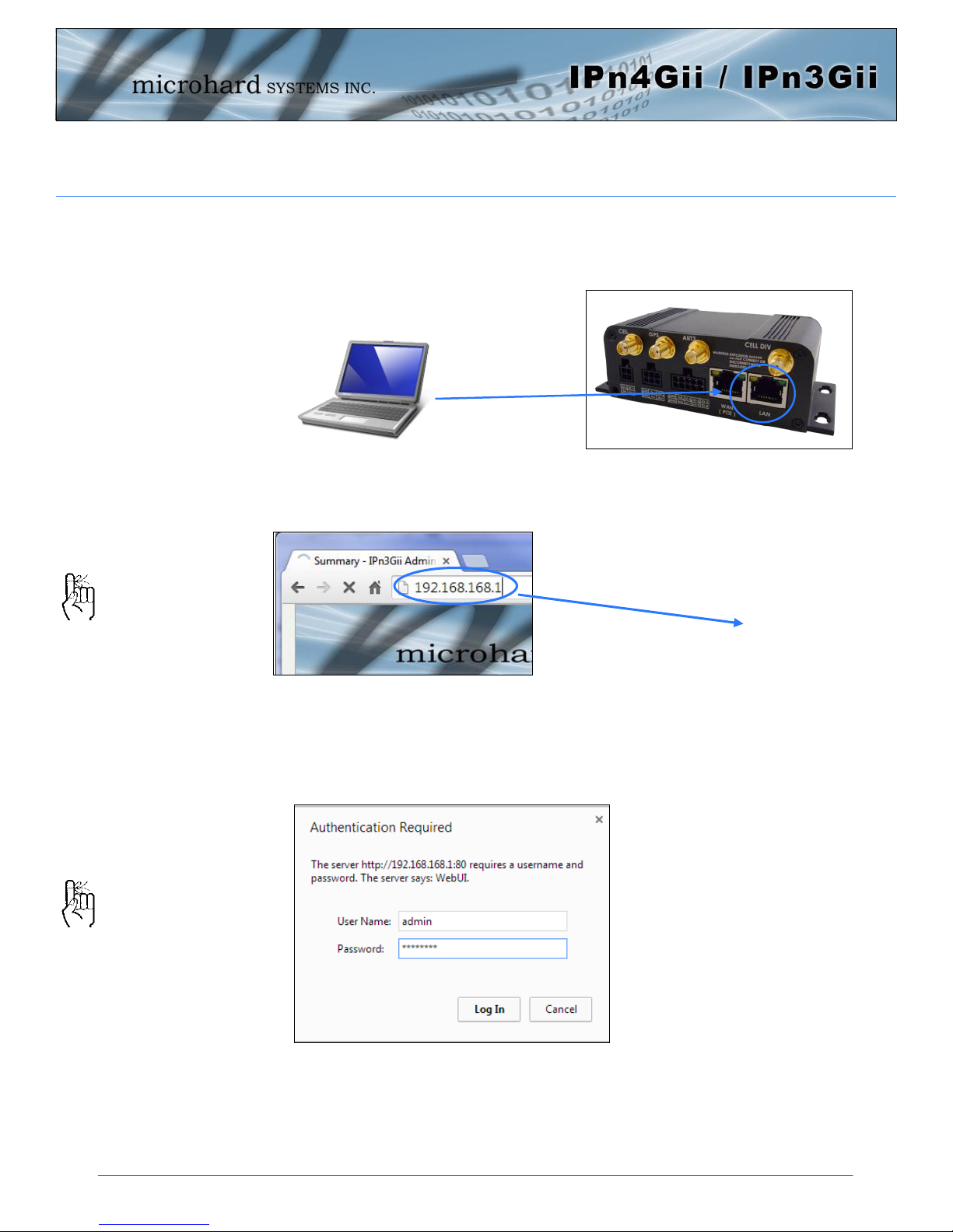
Connect A PC configured for DHCP directly to the LAN port of the IPnXGii, using an
Ethernet Cable. If the PC is configured for DHCP it will automatically acquire a IP Address
from the IPnXGii.
Open a Browser Window and enter the IP address 192.168.168.1 into the address bar.
The factory default network
settings:
IP: 192.168.168.1
Subnet: 255.255.255.0
Gateway: 192.168.168.1
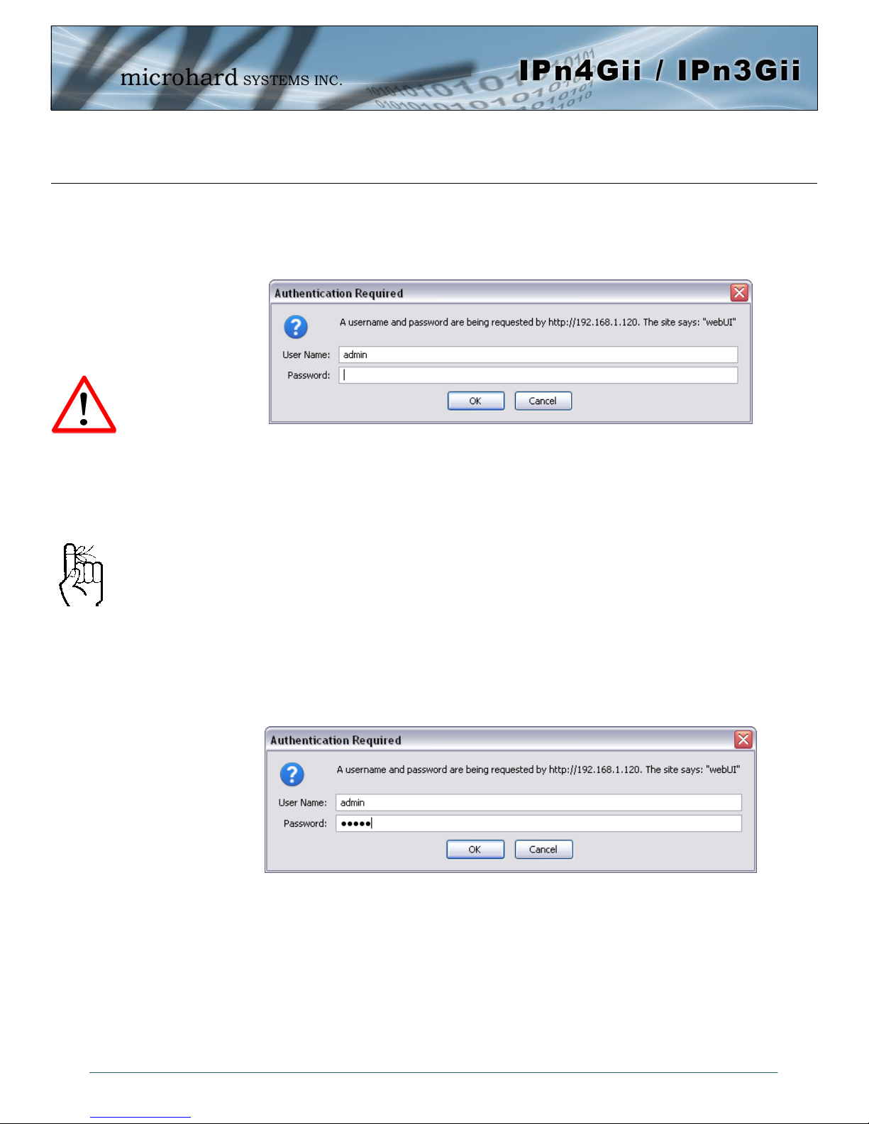
The IPnXGii will then ask for a Username and Password. Enter the factory defaults listed
below.
192.168.168.1
The Factory default login:
User name: admin
Password: admin
The factory default login:
User name: admin
Subnet: admin
It is always a good idea to
change the default admin
login for future security.
© Microhard Systems Inc. 16
Page 17
2.0 Quick Start
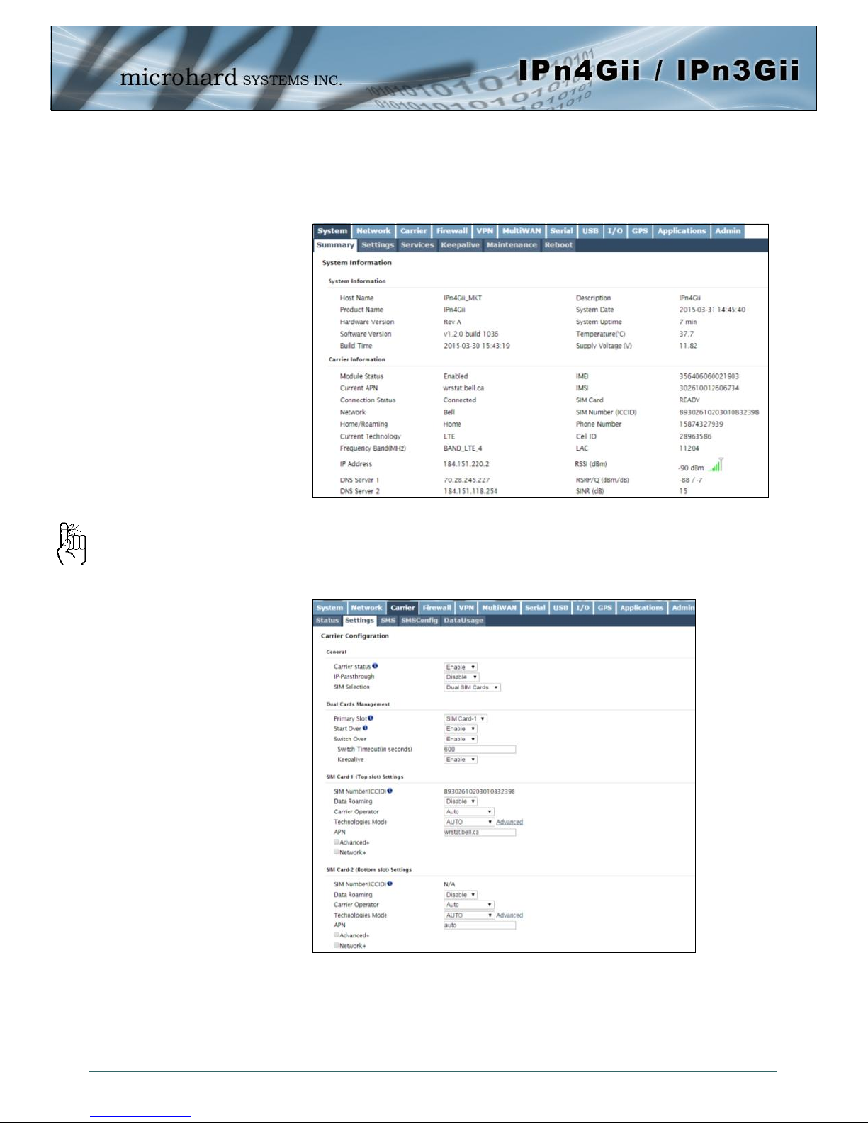
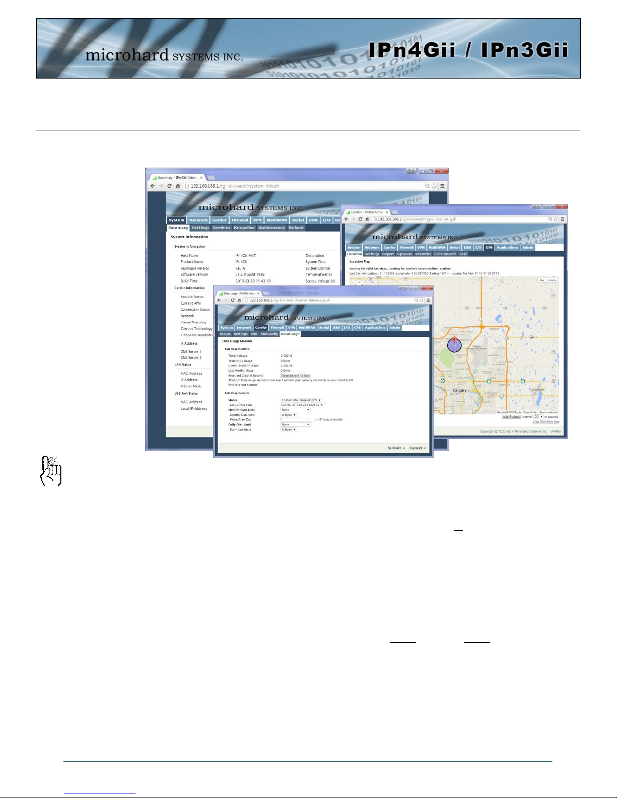
Once successfully logged in, the System Summary page will be displayed.
As seen above under Carrier Status, the SIM card is installed, but an APN has not been
specified. Setting the APN to auto (default) may provide quick network connectivity, but
may not work with some carriers, or with private APN’s. To set or change the APN, click
Auto APN: The IPnXGii will
attempt to detect the carrier
based on the SIM card
installed and cycle through a
list of commonly used APN’s
to provide quick network
connectivity.
on the Carrier > Settings tab and enter the APN supplied by your carrier in the APN field.
Some carriers may also require a Username and Password.
Once the APN and any other required information is entered to connect to your carrier,
click on “Submit”.
Verizon Models do not require a APN and will Auto Connect if a valid SIM card is inserted.
© Microhard Systems Inc. 17
Page 18
2.0 Quick Start
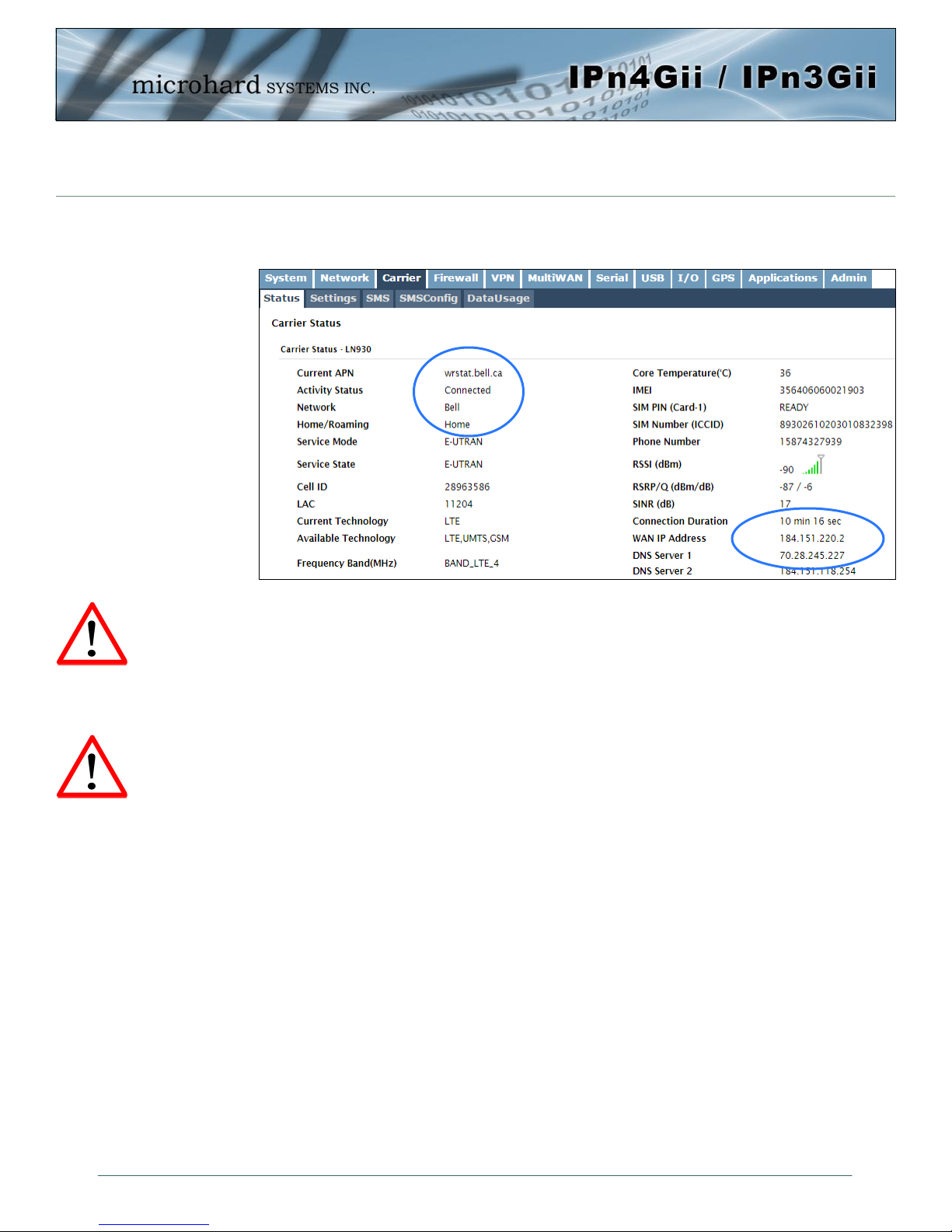
On the Carrier > Status Tab, verify that a WAN IP Address has been assigned by your
carrier. It may take a few minutes, so try refreshing the page if the WAN IP Address
doesn’t show up right away. The Activity Status should also show “Connected”.
If you have set a static IP on your PC, you may need to add the DNS Servers shown in
the Carrier Status Menu to you PC to enable internet access.
Congratulations! Your IPnXGii is successfully connected to your Cellular Carrier.
Ensure the default
passwords are changed.
Set up appropriate firewall
rules to block unwanted
incoming data.
To access devices connected to IPnXGii remotely, one or more of the following must be
configured: IP-Passthrough, Port Forwarding, DMZ. Another option would be to set up a
VPN.
Ensure that all default passwords are changed to limit access to the modem.
For best practices and to limit data charges it is critical to properly set up the firewall.
(Especially important for Public Static IP addresses.)
© Microhard Systems Inc. 18
Page 19
3.0 Hardware Features
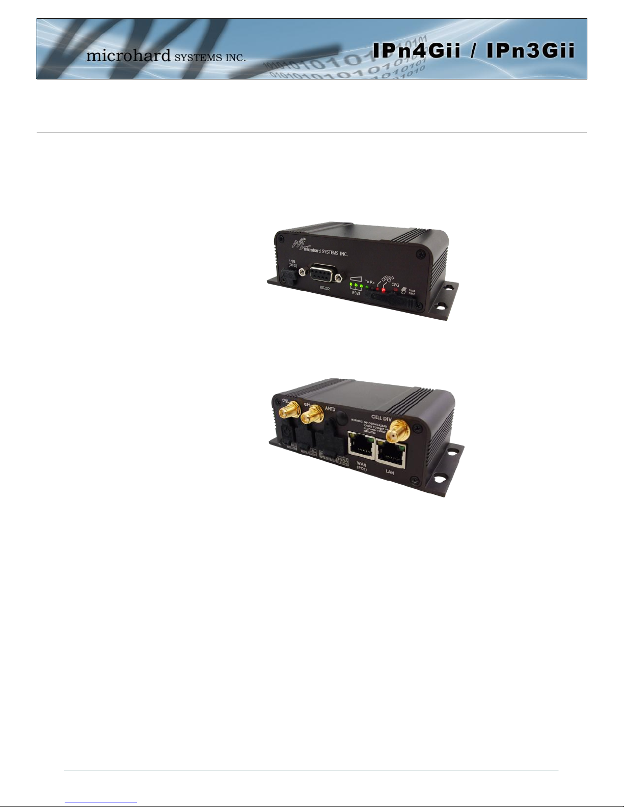
3.1 IPnXGii
The IPnXGii is a fully-enclosed unit ready to be interfaced to external devices.
The IPnXGii Hardware Features Include:
Standard Connectors for:
2 Ethernet Ports (RJ45 - WAN/LAN)
Data Port (RS232/DB9)
COM2 Port (RS232/Console)
4-Pin: MATE-N-LOK Type Connector for Power / I/O 1/2
6-Pin: MATE-N-LOK Type Connector for RS485 Data
10-Pin: MATE-N-LOK Type Connector for RS232 Console / I/O 3-8
Cellular Antenna (SMA Female Antenna Connection x2)
ANT3 Antenna (RP-SMA Female Antenna Connection) (Future)
Status/Diagnostic LED’s for RSSI(x3), Tx, Rx, CELL, CPU
Dual SIM (standard size) Card Slots
CFG Button for factory default / firmware recovery operations
Mounting Holes
Image 3-1: Front View of IPnXGii
Image 3-2: Rear View of IPnXGii
© Microhard Systems Inc. 19
Page 20
3.0 Hardware Features
119.50
9.75
37.00
100.01
2.50
9.75
100.01
108.50
119.50
32.04
13.48
10.48
5.50
4.25
14.50
47.00
20.16
36.58
56.00
71.10
R3.50
Ø7.00
100.01
9.75
37.00
2.50
119.50
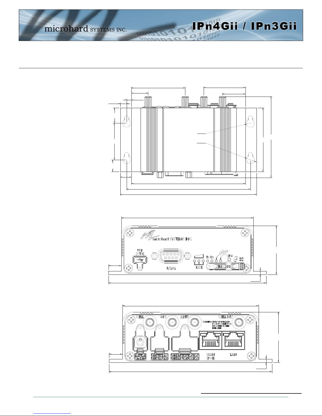
3.1.1 Mechanical Drawings
Drawing 3-1: IPnXGii Top View Dimensions
© Microhard Systems Inc. 20
Drawing 3-2: IPnXGii Front View Dimensions
Drawing 3-3: IPnXGii Rear View Dimensions
Note: All dimension units: Millimeter
Page 21

3.0 Hardware Features
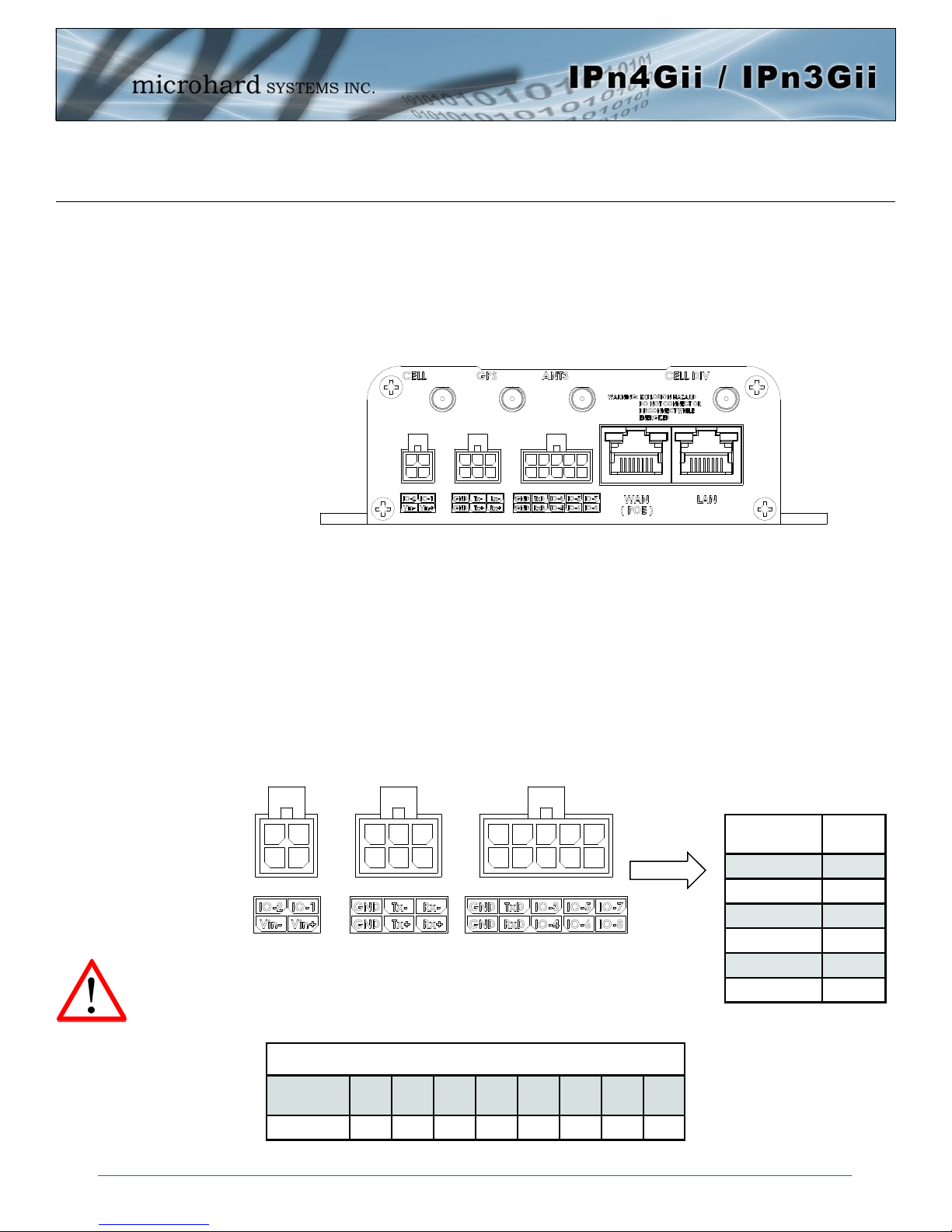
3.1.2 Connectors and Indicators
3.1.2.1 Front
On the front of the IPnXGii is the RS232 (COM2) port, CFG Button, RSSI, Tx, RX, CELL & CPU LED’s as
described below:
Drawing 3-4: IPnXGii Front View
The factory default network
settings:
IP: 192.168.168.1
Subnet: 255.255.255.0
Gateway: 192.168.168.1
The RS232 port is used for serial communication to serial
based end devices. (300bps to 921kbps)
CONFIG (Button) - Holding this button depressed while
powering-up the IPnXGii will boot the unit into FLASH FILE
SYSTEM RECOVERY mode. The default IP address for
system recovery (only - not for normal access to the unit) is
static: 192.168.1.39.
If the unit has been powered-up for some time (>1 minute),
depressing the CFG Button for 8 seconds will result in FACTORY DEFAULTS being restored, including the static factory
IP address. This IP address is useable in a Web Browser for
accessing the Web User Interface.
Tx(Red)/Rx(Green) LED’s - The Tx/Rx LED’s indicate car-
rier (cellular) traffic. Also, during system bootup, the RF &
SGNL LED’s will flash.
CELL LED - Indicates internal cellular module has
power.
Receive Signal Strength Indicator (RSSI) (3x
Green) - As the received signal strength increases,
Signal Level
(dBm)
(-85, 0] ON ON ON
(-90, -85] ON ON FLASH
starting with the furthest left, the number of active
RSSI LEDs increases.
CPU LED - The Status LED indicates that power has
been applied to the module. Flashing indicates bootup or firmware upgrade status.
SIM Cards - These slots are used to install SIM card
(s) provided by the cellular carrier to enable commu-
(-95, -90] ON ON OFF
(-100, -95] ON FLASH OFF
(-105, -100] ON OFF OFF
(-109, -105] FLASH OFF OFF
Other SCANNING SCANNING SCANNING
nication to their cellular network. Ensure that the SIM
card is installed properly by paying attention to the
diagram printed above the SIM card slot. The system
will detect which slot is used.
Name Data Port
DCD 1 O
RXD 2 O
TXD 3 I
DTR 4 I
SG 5
DSR 6 O
RTS 7 I
CTS 8 O
RING 9 O
Table 3-1: RS232 Pin Assignment
RSSI1
(Left)
Table 3-2: RSSI LED’s
RSSI2
(Mid)
Input or
Output
RSSI3
(Right)
© Microhard Systems Inc. 21
Page 22
3.0 Hardware Features
3.1.2 Connectors and Indicators
3.1.2.2 Rear
On the back of the IPnXGii is the Console port (RS232 - Rx/Tx), RS485/422 interface, Programmable I/O,
Dual Ethernet Ports (WAN/LAN) as well as the power connections. The unit also has the SMA(F)
connectors for the Main (TX/RX), the Diversity (RX) antenna’s, and a RP-SMA Female connector for ANT3
The Console (RS232 –Tx/Rx) on the rear of the unit is used for:
AT Command Interface
RS232 serial data (TX, RX)
The RS422/485 Port is a standalone port that can be used in addition to the RS232 Data Port.
Programmable I/O– The IPnXGii has 8 programmable Analog/Digital Inputs or 8x Digital Outputs.
Maximum recommended load for the output pin is 150mA @ 30 Vdc (Vin).
Vin+/Vin– is used to power the unit. The input Voltage range is 9-30 Vdc.
PoE– The IPnXGii can also be powered using Passive PoE on the Ethernet
Port (WAN), via a PoE injector.
Caution: Using a power
supply that does not
provide proper voltage
may damage the modem.
Source
Voltage
9 - 30 Vdc Data Data Data DC+ DC+ Data DC- DC-
Drawing 3-5: IPnXGii Rear View
Ethernet RJ45 Connector Pin Number
1 2 3 4 5 6 7 8
Name
Tx+ O
Tx- O
Rx+ I
Rx- I
Vin -
Vin + I
Table 3-4: Data RS422/485,
Vin Pin Assignments
Input or
Output
© Microhard Systems Inc. 22
Table 3-5: Ethernet PoE Connections
Page 23
4.0 Configuration
4.0 Web User Interface
The factory default network
settings:
IP: 192.168.168.1
Subnet: 255.255.255.0
Gateway: 192.168.168.1
Image 4-0-1: WebUI
Initial configuration of an IPnXGii using the Web User (Browser) Interface (Web UI) method involves the
following steps:
configure a static IP Address on your PC to match the default subnet or if your PC is configured for
DHCP, simply connect a PC to the LAN port of the IPnXGii and it will be assigned a IP address
automatically.
connect the IPnXGii ETHERNET(LAN) port to PC NIC card using an Ethernet cable
apply power to the IPnXGii and wait approximately 60 seconds for the system to load
open a web browser and enter the factory default IP address(192.168.168.1) of the unit:
logon window appears; log on using default Username: admin Password: admin
use the web browser based user interface to configure the IPnXGii as required.
refer to Section 2.0: Quick Start for step by step instructions.
In this section, all aspects of the Web Browser Interface, presented menus, and available configuration
options will be discussed.
© Microhard Systems Inc. 23
Page 24
4.0 Configuration
For security, do not allow the
web browser to remember the
User Name or Password.
It is advisable to change the
login Password. Do not
FORGET the new password
as it cannot be recovered.
4.0.1 Logon Window
Upon successfully accessing the IPnXGii using a Web Browser, the Logon window will appear.
Image 4-0-2: Logon Window
The factory default User Name is: admin
The default password is: admin
Note that the password is case sensitive. It may be changed (discussed further along in this section), but
once changed, if forgotten, may not be recovered.
When entered, the password appears as ’dots’ as shown in the image below. This display format prohibits
others from viewing the password.
The ‘Remember my password’ checkbox may be selected for purposes of convenience, however it is
recommended to ensure it is deselected - particularly once the unit is deployed in the field - for one
primary reason: security.
© Microhard Systems Inc. 24
Image 4-0-3: Logon Window : Password Entry
Page 25
4.0 Configuration
4.1 System
The main category tabs located at the top of the navigation bar separate the configuration of the IPnXGii
into different groups based on function. The System Tab contains the following sub menu’s:
Summary - Status summary of entire radio including network settings,
version information, and radio connection status
Settings - Host Name, System Log Settings, System Time/Date
Services - Enable/Disable and configure port numbers for SSH, Telnet, HTTP
and HTTPS services
Keepalive - Configure System keep alive to ensure network/internet access.
Maintenance - Remote firmware Upgrades, reset to defaults, configuration backup
and restore.
Reboot - Remotely reboot the system.
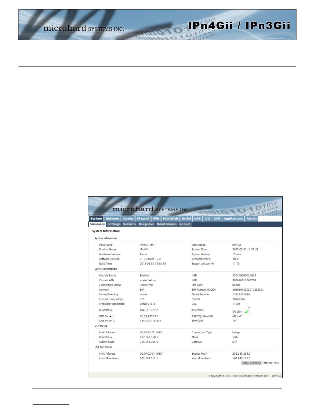
4.1.1 System > Summary
The System Summary screen is displayed immediately after initial login, showing a summary and status of
all the functions of the IPnXGii in a single display. This information includes System Status, Carrier Status,
Cellular & LAN network information, version info, etc.
© Microhard Systems Inc. 25
Image 4-1-1: System Info Window
Page 26
4.0 Configuration
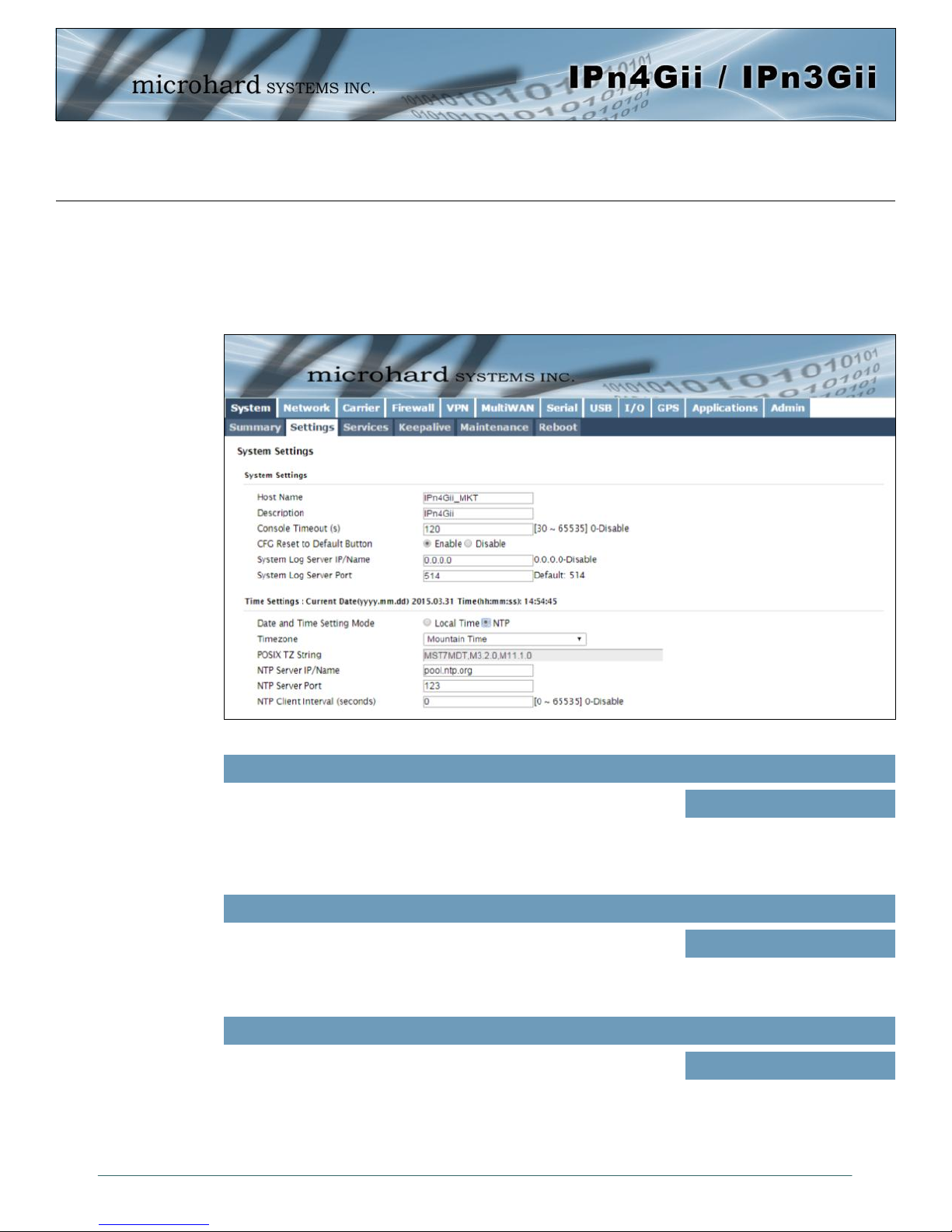
4.1.2 System > Settings
System Settings
Options available in the System Settings menu allow for the configuration of the Host Name, Description,
Console Timeout and System Log server settings.
Image 4-1-2: System Settings > System Settings
Host Name
The Host Name is a convenient identifier for a specific IPnXGii unit.
This feature is most used when accessing units remotely: a convenient
cross-reference for the unit’s WAN/Carrier IP address. This name
appears when logged into a telnet session, or when the unit is
reporting into Microhard NMS System.
Console Timeout (s)
This value determines when a console connection (made via Console
Port or Telnet) will timeout after becoming inactive.
CFG Reset to Default Button
Enabled by default, when the CFG button on the front of the IPnXGii is
held down for 10s while the unit is powered up, the unit will reset and
all settings will be reset to factory defaults. When disabled the unit will
reset, but the settings will not be overwritten.
Values (characters)
IPnXGii (varies)
up to 30 characters
Values (seconds)
60
0-65535
Values (Selection)
Enable
Disable
© Microhard Systems Inc. 26
Page 27
4.0 Configuration
System Syslog Server IP
Network Time Protocol (NTP)
can be used to synchronize the
time and date or computer
systems with a centralized,
referenced server. This can
help ensure all systems on a
network have the same time
and date.
The IPnXGii can report system level events to a third party Syslog server,
which can be used to monitor events reported by the IPnXGii.
IP Address
0.0.0.0
System Syslog Server Port
Enter the UDP listening port of the Syslog Server. The default port number
is generally 514, but could vary from Server to Server.
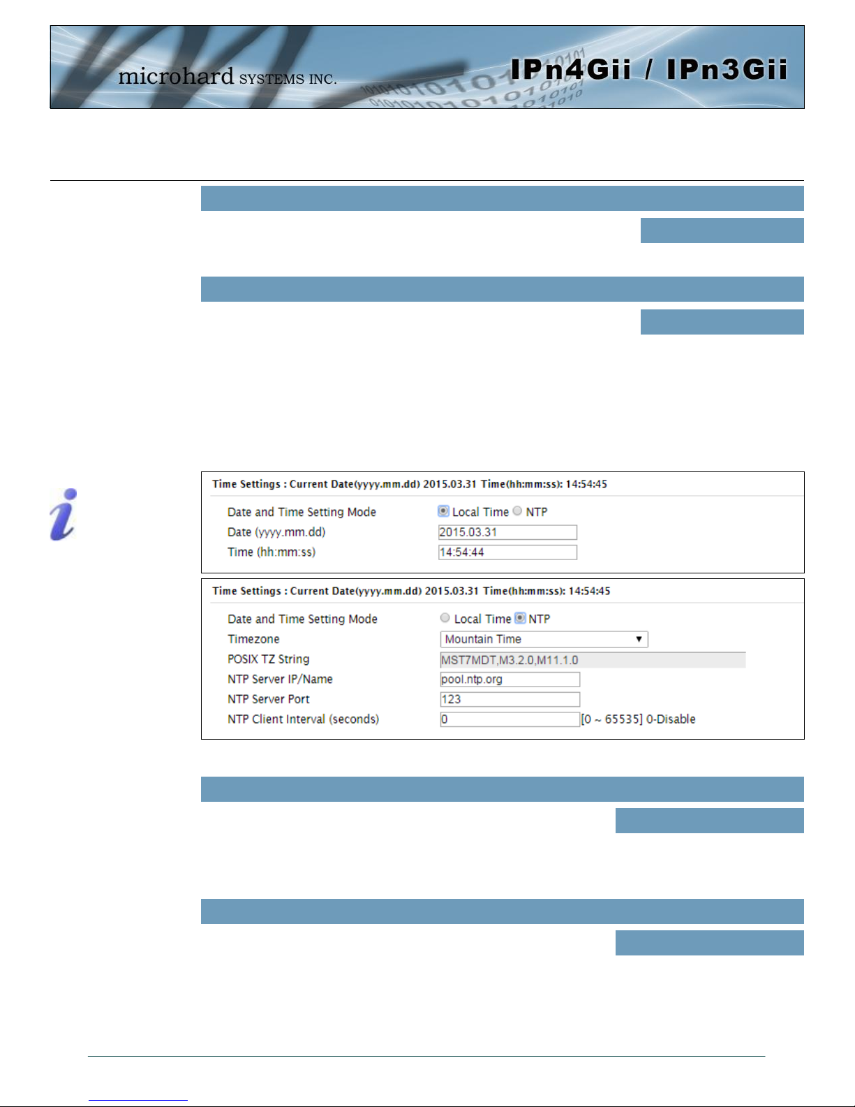
Time Settings
The IPnXGii can be set to use a local time source, thus keeping time on its own, or it can be configured to
synchronize the date and time via a NTP Server. The options and menus available will change depending
on the current setting of the Date and Time Setting Mode, as seen below.
UDP Port
514
Select the Date and Time Setting Mode required. If set for ‘Use
Local Time’ the unit will keep its own time and not attempt to
synchronize with a network server. If ‘Synchronize Date And
Time Over Network’ is selected, a NTP server can be defined.
The calendar date may be entered in this field. Note that the
entered value is lost should the IPnXGii lose power for some
reason.
© Microhard Systems Inc. 27
Image 4-1-3: System Settings > Time Settings
Date and Time Setting Mode
Values (selection)
Use Local Time Source
Synchronize Date And Time
Over Network
Date
Values (yyyy-mm-dd)
2011.04.01 (varies)
Page 28

4.0 Configuration
Time
The time may be entered in this field. Note that the entered
value is lost should the IPnXGii lose power for some reason.
If connecting to a NTP time server, specify the timezone from
the dropdown list.
This displays the POSIX TZ String used by the unit as
determined by the timezone setting.
Enter the IP Address or domain name of the desired NTP time
server.
Enter the IP Address or domain name of the desired NTP time
server.
Values (hh:mm:ss)
11:27:28 (varies)
Timezone
Values (selection)
User Defined (or out of date)
POSIX TZ String
Values (read only)
(varies)
NTP Server
Values (address)
pool.ntp.org
NTP Port
Values (port#)
123
NTP Client Interval
By default the modem only synchronizes the time and date during
system boot up (default: 0), but it can be modified to synchronize at a
regular interval. This process does consume data and should be set
accordingly.
© Microhard Systems Inc. 28
0
Values (seconds)
Page 29
4.0 Configuration
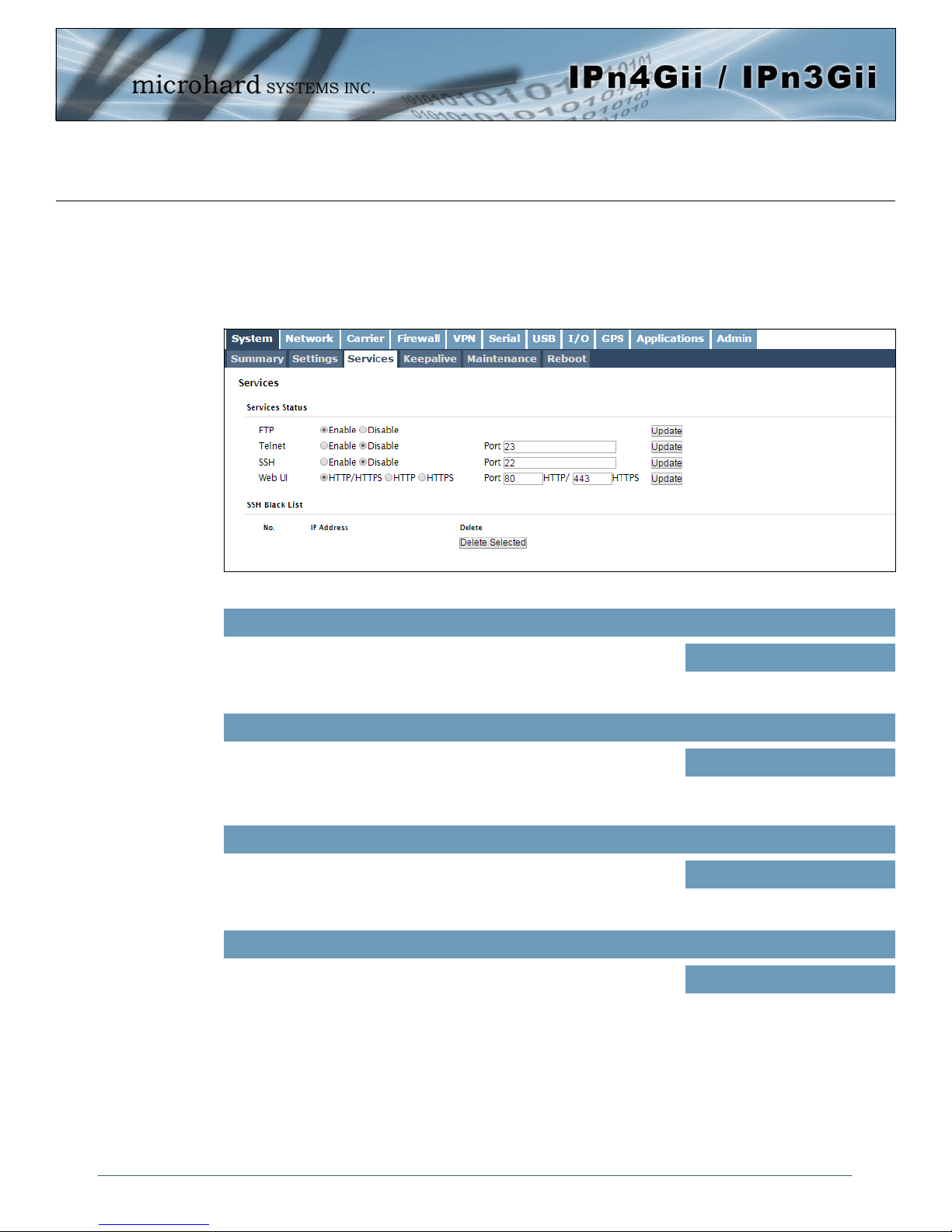
4.1.3 System > Services
Certain services in the IPnXGii can be disabled or enabled for either security considerations or resource/
power considerations. The Enable/Disable options are applied after a reboot and will take affect after each
start up. The Start/Restart/Stop functions only apply to the current session and will not be retained after a
power cycle.
Image 4-1-5: System > Services
The FTP service can be enabled/disabled using the Services Status
Menu. The FTP service is used for firmware recovery operations.
Using the Telnet Service Enable/Disable function, you can disable the
Telnet service from running on the modem. The port used by the
Telnet service can also be modified. The default is 23.
Using the SSH Service Enable/Disable function, you can disable the
SSH service (Port 22) from running on the modem. The port used by
the SSH service can also be modified. The default is 22.
The default web server port for the web based configuration tools used
in the modem is port 80 (http) and port 443 (HTTPS).
Change as required, but keep in mind that if a non standard port is
used, it must be specified in a internet browser to access the unit.
(example: http://192.168.168.1:8080).
FTP
Values (port)
Enable / Disable
Telnet
Values (port)
23
SSH
Values (port)
22
Web UI
Values (selection)
HTTP/HTTPS
HTTP
HTTPS
© Microhard Systems Inc. 29
Page 30
4.0 Configuration
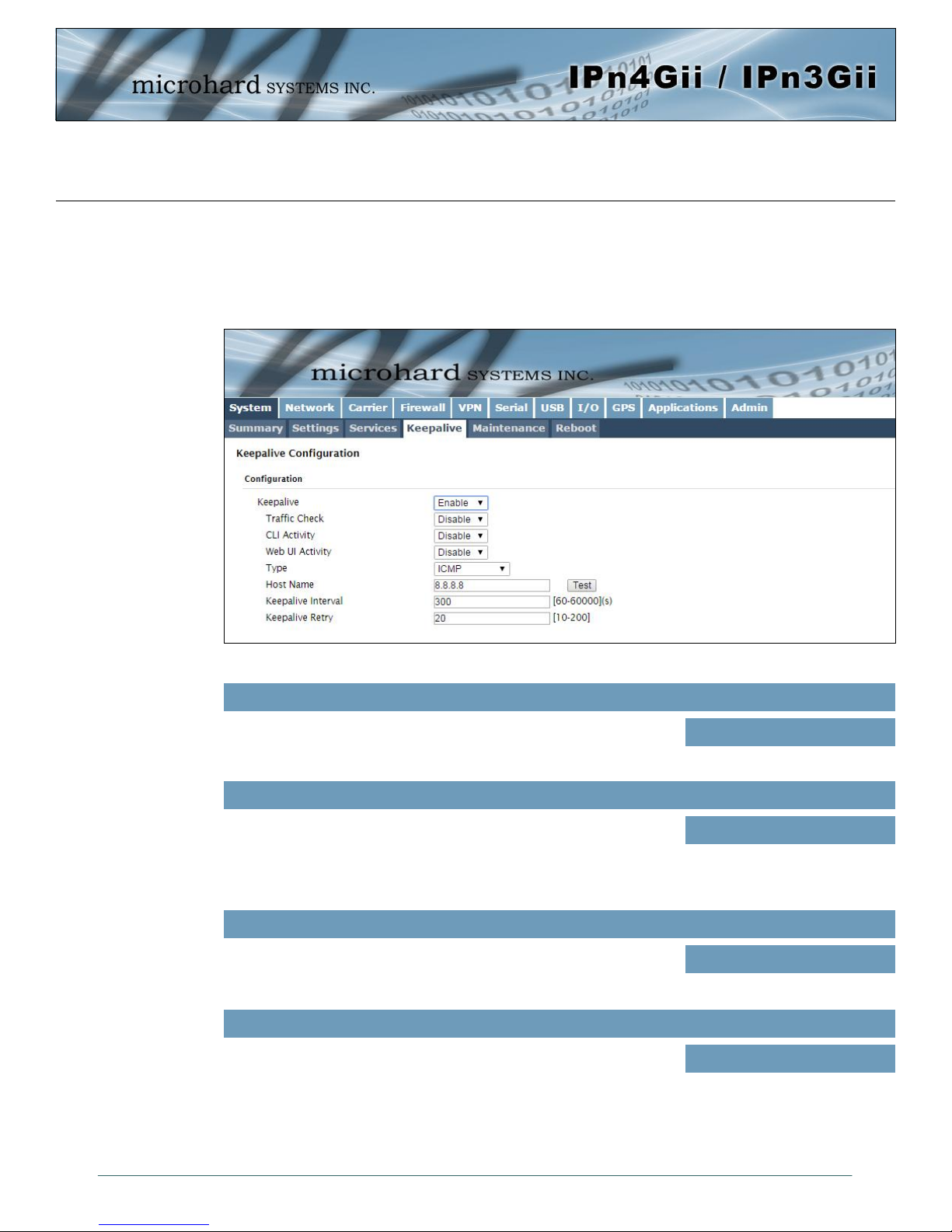
4.1.4 System > Keepalive
The Keep alive tab allows for the configuration of the keep alive features of the IPnXGii. The IPnXGii can
check for activity on the Wireless Interface, The CLI (Command Line Interface), The WEBUI, and ensure
that they are working as expected. In the event that the IPnXGii does not detect activity on a interface it will
reboot to attempt to resolve any issues that may have occurred.
Image 4-1-6: Carrier > Keepalive
Enable or Disable the keep alive functions of the modem. If it is
disabled, the user can configure the Traffic Check separately. The unit
will monitor traffic on the Cell interface.
Monitors traffic on the Cell interface as well as the WAN interface if the
WAN port is configured as independent in the Network Settings. If the
Bullet detects that there is no activity on the above interfaces it will
attempt a ICMP, HTTP or DNS Lookup as configured below to
determine if service has been lost.
Monitors the activity of CLI. If the console isn't accessed within the
certain period which is specified by Console Timeout in SystemSettings web page, the modem will send out the connection request.
Monitors the activity of Web UI. If the Web UI isn't accessed or
refreshed within the certain period which is specified by Console
Timeout in System-Settings web page, the modem will send out the
connection request.
Keep Alive
Values (Selection)
Enable / Disable
Traffic Check
Values (Selection)
Enable / Disable
CLI Activity
Values (Selection)
Enable / Disable
Web UI Activity
Values (Selection)
Enable / Disable
© Microhard Systems Inc. 30
Page 31

4.0 Configuration
Type
Once the connection is lost, the modem will send one of the requests
to the remote host to determine the connection status. If the modem
fails to get the response, it will re-send the request within the seconds
specified by Keepalive Interval below:
ICMP: Send a "ping" request
HTTP: Send a "wget" request to a HTTP server
DNS Lookup: Send a "dsloopup" request to a DNS server
Specify a IP Address or Domain that is used to test the modems
connection. The modem will send out the connection requests to the
specified Host.
The Interval value determines the frequency, or how often, the unit will
send out PING messages to the Host.
The Keepalive Retry is the maximum number of connection failures
such as “Host unreachable” the unit will attempt before the unit will
reboot itself to attempt to correct connection issues. The default
number is 20, and valid value is from 10 to 200.
Values (Selection)
ICMP
HTTP
DNS Lookup
Host Name
Values (IP or Domain)
8.8.8.8
Keepalive Interval
Values (seconds)
60
Keepalive Retry
Values (number)
10
© Microhard Systems Inc. 31
Page 32

4.0 Configuration
4.1.5 System > Maintenance
Firmware Upgrade
Occasional firmware updates may be released by Microhard Systems which may include fixes and/or new
features. The firmware can be updated wirelessly using the WebUI.
Image 4-1-7: Maintenance > Firmware Upgrade
Erase Current Configuration
Check this box to erase the configuration of the IPnXGii unit during the
upgrade process. This will upgrade, and return the unit to factory
defaults, including the default IP Addresses and passwords. Not
checking the box will retain all settings during a firmware upgrade
procedure.
Values (check box)
unchecked
Firmware Image
Use the Browse button to find the firmware file supplied by Microhard
Systems. Select “Upgrade Firmware” to start the upgrade process.
This can take several minutes.
Reset to Default
The IPnXGii may be set back to factory defaults by using the Reset to Default option under System >
Maintenance > Reset to Default. *Caution* - All settings will be lost!!!
© Microhard Systems Inc. 32
Values (file)
(no default)
Page 33

4.0 Configuration
Backup & Restore Configuration
The configuration of the IPnXGii can be backed up to a file at any time using the Backup Configuration
feature. The file can the be restored using the Restore Configuration feature. It is always a good idea to
backup any configurations in case of unit replacement. The configuration files cannot be edited offline, they
are used strictly to backup and restore units.
Image 4-1-8: Maintenance > Reset to Default / Backup & Restore Configuration
Name this Configuration / Backup Configuration
Use this field to name the configuration file. The .config extension will automatically be added to the
configuration file.
Restore Configuration file / Check Restore File / Restore
Use the ‘Browse’ button to find the backup file that needs to be restored to the unit. Use the ‘Check
Restore File’ button to verify that the file is valid, and then the option to restore the configuration is
displayed, as seen above.
© Microhard Systems Inc. 33
Page 34

4.0 Configuration
4.1.6 System > Reboot
The IPnXGii can be remotely rebooted using the System > Reboot menu. As seen below a button ‘OK,
reboot now’ is provided. Once pressed, the unit immediately reboots and starts its boot up procedure.
Image 4-1-9: System > Reboot
© Microhard Systems Inc. 34
Page 35

4.0 Configuration
4.2 Network
4.2.1 Network > Summary
The Network Summary display gives a overview of the currently configured network interfaces including
the Connection Type (Static/DHCP), IP Address, Net Mask, Default Gateway, DNS, and IPv4 Routing
Table.
© Microhard Systems Inc. 35
Image 4-2-1: Network > Network Status
Page 36

4.0 Configuration
4.2.2 Network > LAN
LAN Port Configuration
The factory default
network settings:
IP: 192.168.168.1
Subnet: 255.255.255.0
Gateway: 192.168.168.1
The Ethernet port (RJ45) on the back of the IPnXGii is the LAN port, used for connection of devices on a
local network. By default, this port has a static IP Address. It also, by default is running a DHCP server to
provide IP Addresses to devices that are connected to the physical LAN port (directly or via a switch).
DHCP: Dynamic Host
Configuration Protocol may
be used by networked
devices (Clients) to obtain
unique network addresses
from a DHCP server.
Advantage:
Ensures unique IP addresses
are assigned, from a central
point (DHCP server) within a
network.
Disadvantage:
The address of a particular
device is not ‘known’ and is
also subject to change.
STATIC addresses must be
tracked (to avoid duplicate
use), yet they may be
permanently assigned to a
device.
Within any IP network, each
device must have its own
unique IP address.
Image 4-2-2: Network > LAN Port Configuration
This selection determines if the IPnXGii will obtain an IP address from
a DHCP server on the attached network, or if a static IP address will
be entered. If a Static IP Address is chosen, the fields that follow must
also be populated.
If ‘Static’ Connection Type is selected, a valid IPv4 Address for the
network being used must be entered in the field. If ‘DHCP’ is chosen
this field will not appear and it will be populated automatically from the
DHCP server.
Connection Type
Values (selection)
DHCP
Static
IP Address
Values (IP Address)
192.168.168.1
© Microhard Systems Inc. 36
Page 37

4.0 Configuration
Netmask
A SUBNET MASK is a bit
mask that separates the
network and host (device)
portions of an IP address.
The ‘unmasked’ portion
leaves available the
information required to
identify the various devices
on the subnet.
A GATEWAY is a point within
a network that acts as an
entrance to another network.
In typical networks, a router
acts as a gateway.
If ‘Static’ Connection Type is selected, the Network Mask must be
Values (IP Address)
entered for the Network. If ‘DHCP’ is chosen this field will not appear
and it will be populated automatically from the DHCP server.
255.255.255.0
Default Gateway
If the IPnXGii is integrated into a network which has a defined
gateway, then, as with other hosts on the network, this gateway’s IP
address will be entered into this field. If there is a DHCP server on the
network, and the Connection Type (see previous page) is selected to
be DHCP, the DHCP server will populate this field with the appropriate
gateway address.
A simple way of looking at what the gateway value should be is: If a device has a packet of data is does
not know where to send, send it to the gateway. If necessary - and applicable - the gateway can forward
the packet onwards to another network.
LAN DHCP
A IPnXGii may be configured to provide dynamic host control protocol (DHCP) service to all
attached (either wired or wireless (WiFi)-connected) devices. By default the DHCP service is
enabled, so devices that are connected to the physical Ethernet LAN ports, as well as any
devices that are connected by WiFi will be assigned an IP by the IPnXGii. The LAN DHCP
service is available for each interface, and is located in the add/edit interface menus.
Values (IP Address)
(no default)
Prior to enabling this service,
verify that there are no other
devices - either wired (e.g.
LAN) or wireless with an
active DHCP SERVER
service. (The Server issues
IP address information at the
request of a DHCP Client,
which receives the
information.)
The option is used to enable or disable the DHCP service for devices
connected to the LAN Port(s).
© Microhard Systems Inc. 37
Image 4-2-3: Network > DHCP Server
Mode
Values (selection)
On / Off
Page 38

4.0 Configuration
Start
DNS: Domain Name Service
is an Internet service that
translates easilyremembered domain names
into their not-so-easilyremembered IP addresses.
Being that the Internet is
based on IP addresses,
without DNS, if one entered
the domain name
www.microhardcorp.com (for
example) into the URL line of
a web browser, the website
‘could not be found’).
Select the starting address DHCP assignable IP Addresses. The first
octets of the subnet will be pre-set based on the LAN IP configuration,
and can not be changed.
Set the maximum number of IP addresses that can be assigned by the
IPnXGii.
The DHCP lease time is the amount of time before a new request for a
network address must be made to the DHCP Server.
Specify an alternate gateway for DHCP assigned devices if the default
gateway is not to be used.
Specify a preferred DNS server address to be assigned to DHCP
devices.
Specify the alternate DNS server address to be assigned to DHCP
devices.
Values (IP Address)
192.168.168.100
Limit
Values (integer)
150
Lease Time
Values (minutes)
720
Alternate Gateway
Values (IP Address)
(IP Address)
Preferred DNS Server
Values (IP Address)
(IP Address)
Alternate DNS Server
Values (IP Address)
(IP Address)
© Microhard Systems Inc. 38
Page 39

4.0 Configuration
4.2.3 Network > WAN
WAN Configuration
The WAN configuration refers to the wired WAN connection on the IPnXGii. The WAN port can be used to
connect the IPnXGii to other networks, the internet and/or other network resources.
DHCP: Dynamic Host
Configuration Protocol may
be used by networked
devices (Clients) to obtain
unique network addresses
from a DHCP server.
Advantage:
Ensures unique IP addresses
are assigned, from a central
point (DHCP server) within a
network.
Disadvantage:
The address of a particular
device is not ‘known’ and is
also subject to change.
STATIC addresses must be
tracked (to avoid duplicate
use), yet they may be
permanently assigned to a
device.
Image 4-2-4: Network > WAN Configuration
Use this to set the function of the physical WAN RJ45 port. If set to
independent WAN , the physical WAN port will operate as a standard
WAN port. Alternatively it can be configured to be bridged to the LAN,
and operate as a second LAN port, or even as an independent LAN.
This selection determines if the IPnXGii will obtain an WAN IP address
from a DHCP server, or if a static IP address will be entered. If a Static
IP Address is chosen, the fields that follow must also be populated.
If ‘Static’ Connection Type is selected, a valid IPv4 Address for the
network being used must be entered in the field. If ‘DHCP’ is chosen
this field will not appear and it will be populated automatically from the
DHCP server.
If ‘Static’ Connection Type is selected, the Network Mask must be
entered for the Network. If ‘DHCP’ is chosen this field will not appear
and it will be populated automatically from the DHCP server.
Working Mode
Values (selection)
Independent WAN
Bridged with LAN Port
Independent LAN
Connection Type
Values (selection)
DHCP
Static
IP Address
Values (IP Address)
(no default)
Netmask
Values (IP Address)
(no default)
© Microhard Systems Inc. 39
Page 40

4.0 Configuration
Default Gateway
If the IPnXGii is integrated into a network which has a defined
gateway, then, as with other hosts on the network, this gateway’s IP
address will be entered into this field. If there is a DHCP server on the
network, and the Connection Type (see previous page) is selected to
be DHCP, the DHCP server will populate this field with the appropriate
gateway address.
DNS (Domain Name Service) Servers are used to resolve domain
names into IP addresses. If set to auto and the Connection Type is set
for DHCP the DHCP server will populate this field and the value set
can be viewed on the Network > Status page. To add additional static
servers, enter them here.
Values (IP Address)
(no default)
WAN DNS Servers
Values (IP Address)
(no default)
© Microhard Systems Inc. 40
Page 41

4.0 Configuration
4.2.4 Network > DHCP
The DHCP menu allows a user to view the current DHCP assignments and remaining lease time, as well
as logically bind a MAC address to an IP address. This is often used in cases where it is desired to use
DHCP to assign IP addresses, but a known address must be given to specific devices (e.g. Port
Forwarding). To configure the actual DHCP server, and to assign the valid IP Address ranges, use the
configuration tools under the LAN menu.
Image 4-2-5: Network > DHCP Leases
For future reference purposes, you must name the MAC binding rules.
Enter the physical MAC address of the device or interface that will be
assigned the specified IP Address if it requests a DHCP address.
Enter the IP address to be assigned to the MAC address. Ensure this
is a valid address on the current subnet.
NAME
Values
(no default)
MAC Address
Values
(no default)
IP Address
Values
(no default)
© Microhard Systems Inc. 41
Page 42

4.0 Configuration
4.2.5 Network > DDNS
Unless a carrier issues a Static IP address, it may be desirable to use a Dynamic DNS (DDNS) service to
track dynamic IP changes and automatically update DNS services. This allows the use of a constant
resolvable host name for the IPnXGii.
Image 4-2-6: Carrier > Traffic Watchdog
DDNS Status
This selection allows the use of a Dynamic Domain Name Server
(DDNS), for the IPnXGii.
This is a list of supported Dynamic DNS service providers. Free and
premium services are offered, contact the specific providers for more
information.
Enter a valid user name for the DDNS service selected above.
Enter a valid password for the user name of the DDNS service
selected above.
Values (Selection)
Enable / Disable
Service
Values (selection)
changeip
dyndns
eurodyndns
hn
noip
ods
ovh
regfish
tzo
zoneedit
User Name
Values (characters)
(none)
Password
Values (characters)
(none)
Host
This is the host or domain name for the IPnXGii as assigned by the
DDNS provider.
© Microhard Systems Inc. 42
Values (domain name)
(none)
Page 43

4.0 Configuration
4.2.3 Network > Routes
Static Routes Configuration
It may be desirable to have devices on different subnets to be able to talk to one another. This can be
accomplished by specifying a static route, telling the IPnXGii where to send data.
Image 4-2-7: Network > Routes
Routes can be names for easy reference, or to describe the route
being added.
Enter the network IP address for the destination.
Specify the Gateway used to reach the network specified above.
Enter the Netmask for the destination network.
Name
Values (characters)
(no default)
Destination
Values (IP Address)
(192.168.168.0)
Gateway
Values (IP Address)
192.168.168.1
Netmask
Values (IP Address)
255.255.255.0
© Microhard Systems Inc. 43
Page 44

4.0 Configuration
Metric
In some cases there may be multiple routes to reach a destination.
The Metric can be set to give certain routes priority, the lower the
metric is, the better the route. The more hops it takes to get to a
destination, the higher the metric.
Values (Integer)
255.255.255.0
Interface
Define the exit interface. Is the destination a device on the LAN, LAN1
(If physical WAN port is bridged as an independent LAN), 3G/4G
(cellular), USB or the WAN?
4.2.7 Network > Ports
The Network > Ports menu can be used to determine the characteristics of the physical Ethernet interfaces
on the IPnXGii. As seen below the Mode (Auto/Manual), Auto-Negotiation, Speed (10/100Mbit/s) and the
Duplex (Full/Half) can all be configured on the IPnXGii.
Values (Selection)
LAN / LAN1 / WAN / Cell / USB
None
4.2.8 Network > Device List
The Network > Device List shows the current ARP table for the local network adapter. The MAC address
and IP address are shown, however not only DHCP assigned devices are listed in the device list, any
devices, even those statically assigned, that are connected through the local network interface (RJ45) are
displayed, including those connected through a hub or switch.
© Microhard Systems Inc. 44
Image 4-2-8: Network > Ports
Image 4-2-9: Network > Device List
Page 45

4.0 Configuration
4.3 Carrier
4.3.1 Carrier > Status
The Carrier Status window provides complete overview information related to the Cellular Carrier portion of
the IPnXGii. A variety of information can be found here, such as Activity Status, Network (Name of
Wireless Carrier connected), Data Service Type(WCDMA/HSPA/HSPA+/LTE etc), Frequency band, Phone
Number etc.
Not all statistics parameters displayed are applicable.
The Received and Transmitted bytes and packets indicate the respective amount of data which has been
moved through the radio.
The Error counts reflect those having occurred on the wireless link.
© Microhard Systems Inc. 45
Image 4-3-1: Carrier > Status
Page 46

4.0 Configuration
4.3.2 Carrier > Settings
The parameters within the Carrier Configuration menu must be input properly; they are the most basic
requirement required by your cellular provider for network connectivity. The IPn3Gii/4Gii can support dual
SIM cards, as described below either slot can be specified as the primary slot and if a connectivity issue
occurs, the unit can be configured to automatically switch to the alternate SIM card.
Image 4-3-2: Carrier > Settings
Carrier Status
Carrier Status is used to Enable or Disable the connection to the
Cellular Carrier. By default this option is enabled.
Values (Selection)
Enable / Disable
IP-Passthrough
IP pass-through allows the WAN IP address to be assigned to the
device connected to the LAN or WAN ports. In this mode the Bullet is
for the most part transparent and forwards all traffic to the device
connected to the selected Ethernet port except that listed below:
The WebUI port (Default Port:TCP 80), this port is retained for
remote management of the Bullet. This port can be changed to a
different port under the System > Services Menu.
The SNMP Listening Port (Default Port: UDP 161).
The virtual IP address is configurable to allow access to the unit on the
LAN/WAN connector once IP-Passthrough has been enabled.
The firewall/rules must be configured to allow traffic, all incoming
carrier traffic is blocked by default.
© Microhard Systems Inc. 46
Values (Selection)
Disable
Ethernet (LAN)
WAN
Page 47

4.0 Configuration
SIM Selection
The IPnXGii supports one or two SIM cards to be installed. By default
the primary SIM is the top SIM, and the unit will try to connect using
SIM1 first, and then if it fails to connect, or loses connection to a valid
carrier, it will then attempt SIM2.
This behavior can be modified using the Dual Cards Management
section below.
Dual Cards Management
By default the Primary SIM is the SIM installed into the SIM1 slot on
the unit. The SIM card installed into the Primary slot will be the Cellular
Carrier in which the IPnXGii will attempt to make a connection with.
This can be modified here.
Start Over allows the IPnXGii to use the secondary slot to establish a
connection with the cellular carrier in the case that the primary card is
not installed or is otherwise not functioning.
Values (Selection)
Dual SIM Cards
SIM Card-1 Only
SIM Card-2 Only
Primary Slot
Values (Selection)
SIM Card-1
SIM Card-2
Start Over
Values (Selection)
Enable / Disable
Switch Over
If enabled this feature allows the IPnXGii to switch from the currently
connected SIM (Carrier), to the alternate after it has determined that
the current carrier is not reachable. The Switch Timeout determines
when this will happen.
The amount of inactivity(time) to the current SIM (Carrier), before the
IPNXGii will switch to the alternate SIM(Carrier).
This allows the IPnXGii to use the currently configured System >
Keepalive settings to determine how to check if the IPnXGii has lost
connection to the current Carrier/SIM.
Values (Selection)
Enable / Disable
Switch Timeout
Values (Selection)
600
Keepalive
Values (Selection)
Enable / Disable
© Microhard Systems Inc. 47
Page 48

4.0 Configuration
SIM Card-1 Settings
Data Roaming
This feature allows the disabling or enable of data roaming. When data
roaming is enabled the modem will be allowed to use data when in
roaming status. It is not recommended to allow roaming unless the
appropriate data plans are in place.
In some cases, a user may want to lock onto certain carrier to avoid
data roaming. There were four options presented to a user to choose
from, Auto, SIM based, Scan & Select and Fixed.
Auto will allow the unit to pick the carrier automatically. Data
roaming is permitted.
SIM based will only allow the unit to connect to the network
indicated by the SIM card used in the unit.
Manual will scan for available carriers and allow a user to select
from the available carriers. It takes 2 to 3 minutes to complete a
scan.
Fixed allows a user to enter the carrier code (numerical) directly and
then the unit will only connect to that carrier.
Select the valid types of Carrier connections allowed.
For example if set to auto the IPn3Gii will connect to
any data type. If set to 3G-WCDMA only, the IPn3Gii
will only allow connection to 3G related technologies,
and not allow the device to connect to lesser (slower)
technologies.
Verizon IPn4Gii Models: AUTO:LTE Only
Values (IPn3Gii)
AUTO
3G-WCDMA Only
2G-GPRS Only
Values (Selection)
Enable / Disable
Carrier Operator
Values (Selection)
Auto
Based on SIM
Manual
Fixed
Technologies Mode
Values (IPn4Gii)
AUTO
LTE Only
WCDMA Only
GSM Only
LTE,WCDMA
WCDMA, GSM
LTE, GSM
The APN is required by every Carrier in order to connect to their
networks. The APN defines the type of network the Bullet is connected
to and the service type. Most Carriers have more than one APN,
usually many, dependant on the types of service offered.
Auto APN (default) may allow the unit to quickly connect to a carrier, by cycling through a predetermined
list of common APN’s. Auto APN will not work for private APN’s or for all carriers.
IPn4Gii Verizon models initialized on the Version network will
automatically configure the required settings needed to establish a
connection with Verizon as a Wireless Carrier.
© Microhard Systems Inc. 48
APN (Access Point Name)
Values (characters)
auto
Connect Mode (Verizon)
Values (characters)
Verizon Auto Connection
Defined Network (Test)
Page 49

4.0 Configuration
Advanced+
SIM Pin
The SIM Pin is required for some international carriers. If supplied and
required by the cellular carrier, enter the SIM Pin here.
Sets the authentication type required to negotiate with peer.
PAP - Password Authentication Protocol.
CHAP - Challenge Handshake Authentication Protocol.
Only required if the carrier requires a User Name and Password.
A User Name may be required for authentication to a remote peer.
Although usually not required for dynamically assigned IP addresses
from the wireless carrier. Varies by carrier.
Enter the password for the user name above. May not be required by
some carriers, or APN’s
Values (characters)
(none)
Authentication
Values (Selection)
Device decide (AUTO)
PAP
CHAP
No Auth
User Name
Values (characters)
Carrier/peer dependant
Password
Values (characters)
Carrier/peer dependant
Dial-on-Demand (3G)
If disabled, the modem will always remain connected. The default is
Disabled.
Values (selection)
Disable / Enable
Dial Number (3G)
Sets the number to be dialed. Carrier dependant, the default number is
*99***1#
Values (String)
*99***1#
Dialing Max Retries (3G)
The maximum amount of attempts to dial and establish a connection. The
default is 0, which means that there is no maximum and the modem will
keep trying indefinitely.
Values
0-100
Idle Time Out (3G)
The maximum amount of time to pass before modem will timeout. The
default is 0 seconds.
© Microhard Systems Inc. 49
Values (seconds)
0-65535
Page 50

4.0 Configuration
Connect Time Out (3G)
The maximum amount of time to wait for a connection The default is 90
seconds.
Sets the modems connect string if required by the carrier. Not usually
required to be modified in North America.
Network+
In some cases the Static IP address must be entered in this field if
assigned by a wireless carrier. In most cases the IP will be read from
the SIM card and this field should be left at the default value.
If enabled the Bullet with use the DNS server as specified
automatically by the service provider.
Values (seconds)
0-65535
Connect String (3G)
Values (string)
CONNECT
IP Address
Values (IP Address)
(none)
Use Remote DNS
Values (selection)
Enable / Disable
Default Route
Use this interface as the default route for all outbound traffic unless
specified in the Network > Routes table.
Values (Selection)
Yes / No
IP-Passthrough Mode
When unit is set to operate in IP-Passthrough mode in the general
settings, this will allow the unit to automatically assign the carrier IP to
the end device or use the specified Gateway /Netmask.
Values (Selection)
Auto / Manual
DNS-Passthrough
When enabled DNS-Passthrough will pass on the WAN assigned DNS
information to the end device.
SIM Card-2 Settings
Settings for SIM Card-2 are identical to that of SIM Card-1, refer to the previous section for information on
how to configure SIM Card-2.
Values (Selection)
Enable / Disable
© Microhard Systems Inc. 50
Page 51

4.0 Configuration
4.3.3 Carrier > SMS
SMS Command History
The SMS menu allows a user to view the SMS Command History and view the SMS messages on the SIM
Card.
Image 4-3-3: SMS > SMS Command History
Send SMS Message
The SMS messages can be sent directly from the IPnXGii WebUI interface. Also, the SMS message
history can be viewed.
Image 4-3-4: SMS > SMS Send
© Microhard Systems Inc. 51
Page 52

4.0 Configuration
4.3.4 Carrier > SMS Config
SMS messages can be used to remotely reboot or trigger events in the IPnXGii. SMS alerts can be set up
to get SMS messages based on system events such as Roaming status, RSSI,
Ethernet Link Status or IO Status.
System SMS Command
Image 4-3-5: SMS > SMS Configuration
This option allows a user to enable or disable to use of the following
SMS commands to reboot or trigger events in the IPnXGii:
MSC#REBOOT Reboot system
MSC#NMS Send NMS UDP Report
MSC#WEB Send web client inquiry
MSC#MIOP1 open I/O ouput1
MSC#MIOP2 open I/O ouput2
MSC#MIOP3 open I/O ouput3
MSC#MIOP4 open I/O ouput4
MSC#MIOP5 open I/O ouput5
MSC#MIOP6 open I/O ouput6
MSC#MIOP7 open I/O ouput7
MSC#MIOP8 open I/O ouput8
MSC#MIOC1 close I/O ouput1
MSC#MIOC2 close I/O ouput2
MSC#MIOC3 close I/O ouput3
If enabled, the IPnXGii will only accept and execute commands
originating from the phone numbers in the Phone Filter List. Up to 6
numbers can be added.
MSC#MIOC4 close I/O ouput4
MSC#MIOC5 close I/O ouput5
MSC#MIOC6 close I/O ouput6
MSC#MIOC7 close I/O ouput7
MSC#MIOC8 close I/O ouput8
MSC#EURD0 trigger event report0
MSC#EURD1 trigger event report1
MSC#EURD2 trigger event report2
MSC#EURD3 trigger event report3
MSC#GPSR0 trigger gps report0
MSC#GPSR1 trigger gps report1
MSC#GPSR2 trigger gps report2
MSC#GPSR3 trigger gps report3
Status
Values (Selection)
Enable / Disable
Set Phone Filter
Values (Selection)
Enable / Disable
© Microhard Systems Inc. 52
Page 53

4.0 Configuration
System SMS Alerts
Image 4-3-6: SMS > SMS Alerts
Enable SMS Alerts. IF enabled SMS alerts will be send when
conditions are met as configured to the phone numbers listed.
SMS Alerts can be sent to up to 6 different phone numbers that are
listed here.
SMS alerts, when active, will be sent out at the frequency defined
here.
Enable or disable the RSSI alerts.
Status
Values (Selection)
Enable / Disable
Received Phone Numbers
Values (Selection)
(no default)
Time Interval(s)
Values (Seconds)
300
RSSI Check
Values (Selection)
Disable RSSI check
Enable RSSI check
© Microhard Systems Inc. 53
Page 54

4.0 Configuration
RSSI Check
Set the threshold for RSSI alerts.
Enable or disable SMS Alerts for Roaming Status.
The IPnXGii can send alerts based on the roaming status. Data rates
during roaming can be expensive and it is important to know when a
device has started roaming.
Enable or disable SMS Alerts for the Ethernet Link status of the LAN
RJ45 port.
Values (dBm)
-99
Carrier Network
Values (Selection)
Disable Roaming Check
Enable Roaming Check
Home / Roaming Status
Values (Selection)
In Roaming
Changed or In Roaming
Changed to Roaming
Ethernet
Values (Selection)
Disable Ethernet check
Enable Ethernet check
Ethernet Link Status
The status of the Ethernet Link of the LAN (RJ45) can be used to send
SMS Alerts. The link status may indicate an issue with the connected
device.
SMS Alerts can be sent based on the state changes of the Digital I/O
lines.
Values (Selection)
Changed
In no-link
Changed or in no-link
Changed to no-link
I/O Status
Values (Selection)
Disable IO Check
Enable: INPUT Changed
Enable: Output Changed
Enable: INPUT or OUTPUT
Changed.
© Microhard Systems Inc. 54
Page 55

4.0 Configuration
4.3.5 Carrier > Data Usage
The Data Usage tool on the IPnXGii allows users to monitor the amount of cellular data consumed. Since
cellular devices are generally billed based on the amount of data used, alerts can be triggered by setting
daily and/or monthly limits. Notifications can be sent using SMS or Email, allowing a early warning if
configurable limits are about to be exceeded. The usage data reported by the Data Usage Monitor may not
match the data reported by the carrier, but it gives the users an idea of the bandwidth consumed by the
IPnXGii.
If enabled the IPnXGii will track the amount of cellular data consumed. If
disabled, data is not recorded, even in the Current Data Usage display.
© Microhard Systems Inc. 55
Image 4-3-7: Carrier > Data Usage
Status
Values (selection)
Disable
Enable
Page 56

4.0 Configuration
Monthly/Daily Over Limit
Select the notification method used to send alerts when daily or monthly
thresholds are exceeded. If none is selected, notifications will not be sent,
but data usage will be recorded for reference purposes.
Image 4-3-9: Data Usage > SMS Config
Monthly/Daily Data Unit
Select the data unit to be used for data usage monitoring.
Select the data limit for the day or month, used in connection with the data
unit is the previous field. If you want to set the limit to 250 Mbytes, select M
Bytes for the data unit, and 250 for the data limit.
Values (selection)
None
Send Notice SMS
Send Notice Email
Values (selection)
Bytes / K Bytes / M Bytes
G Bytes
Data Limit
Values (1-65535)
500
For Monthly tracking, select the day the billing/data cycles begins. On this
day each month the IPnXGii will reset the data usage monitor numbers.
If SMS is selected as the notification method, enter the phone number to
send any SMS messages generated when the data usage exceeds the
configured limits.
Image 4-3-10: Data Usage > Email Config
Period Start Day
Values (1-31)
1 (Day of Month)
Phone Number
Values (phone)
+1403
© Microhard Systems Inc. 56
Page 57

4.0 Configuration
Mail Subject
If Email is selected as the notification method, enter the desired email
subject line for the notification email sent when daily and/or monthly usage
limits are exceeded.
If Email is selected as the notification method, enter the SMTP server
details for the account used to send the Email notifications. Domain or IP
address with the associated port as shown.
If Email is selected as the notification method, enter the username of the
Email account used to send Emails.
If Email is selected as the notification method, enter the password of the
Email account used to send Emails. Most email servers require
authentication on outgoing emails.
Enter the email address of the individual or distribution list to send the
email notification to.
Values (string)
Daily/Monthly Data Usage
Notice
Mail Server(IP/Name)
Values (xxx:port)
smtp.gmail.com:465
Username
Values (username)
@gmail.com
Password
Values (string)
***
Mail Recipient
Values (xx@xx.xx)
host@
© Microhard Systems Inc. 57
Page 58

4.0 Configuration
4.4 Firewall
4.4.1 Firewall > Summary
The Firewall Summary allows a user to see detailed information about how the firewall is operating. The
All, Filter, Nat, Raw, and Mangle options can be used to view different aspects of the firewall.
© Microhard Systems Inc. 58
Image 4-4-1: Firewall > Status
Page 59

4.0 Configuration
4.4.2 Firewall > General
The General Firewall settings allow users to enable or disable the firewall, and to decide which areas of the
modem to protect. The Firewall can also be reset to factory defaults from this area of the WebUI.
In a cellular device such as this, it is highly recommended to configure the firewall to protect any devices
connected to the modem, and to control data usage. This is especially important with units set up with a
public IP address as the modem is effectively on the public internet and is susceptible to a wide range of
threats which may severely impact the data usage. This can be avoided by blocking all Cellular traffic and
setting up specific rules to either open only used ports, or even restrict access to specific IP/networks.
For best practices and to
control data usage it is
critical that the firewall be
configured properly.
It is recommended to block
all incoming Cellular traffic
and create rules to open
specific ports and/or use
ACL lists to limit incoming
connections.
When Carrier Request is
set to ‘Allow’ the modem is
open to anyone, this is not
recommended as it may
impact data usage from
unwanted sources.
Image 4-4-2: Firewall > General
WAN Remote Management
Allow remote management of the IPnXGii on the WAN side using the
WebUI on port 80(HTTP), and 443 (HTTPS). If disabled, the configuration
can only be accessed from the LAN (or Cellular if enabled)..
Carrier Remote Management
Allow remote management of the IPnXGii from the Cellular side of using
the WebUI on port 80(HTTP), and 443 (HTTPS). If disabled, the
configuration can only be accessed from the LAN (or WAN if enabled)..
When Blocked the IPnXGii will block all requests from devices on the WAN
unless specified otherwise in the Access Rules, MAC List, IP List
configurations. Access to ports 80 (HTTP) and 443 (HTTPS-if enabled), is
still available unless disabled in the WAN Remote Management option.
When Blocked all requests from devices on the Cellular (Wireless Carrier)
side will be blocked, unless specified otherwise in the Access Rules, MAC
List, IP List configurations. Access to ports 80 (HTTP) and 443 (HTTPS-if
enabled), is still available unless disabled in the 4G Remote Management
option.
Values
Enable / Disable
Values
Enable / Disable
WAN Request
Values
Block / Allow
Carrier Request
Values
Block / Allow
© Microhard Systems Inc. 59
Page 60

4.0 Configuration
LAN to WAN Access Control
Allows or Blocks traffic from the LAN accessing the WAN unless specified
otherwise using the Access Rules, MAC, and IP List configuration.
LAN to Carrier Access Control
Allows or Blocks traffic from the LAN accessing the Cell connection unless
specified otherwise using the Access Rules, MAC, and IP List
configuration.
The Anti-Spoof protection is to create some firewall rules assigned to the
external interface (WAN & Cellular) of the firewall that examines the source
address of all packets crossing that interface coming from outside. If the
address belongs to the internal network or the firewall itself, the packet is
dropped.
Packet Normalization is the normalization of packets so there are no
ambiguities in interpretation by the ultimate destination of the packet. The
scrub directive also reassembled fragmented packets, protecting some
operating systems from some forms of attack, and drops TCP packets that
have invalid flag combinations.
Values
Block / Allow
Values
Block / Allow
Anti-Spoof
Values
Enable / Disable
Packet Normalization
Values
Enable / Disable
The Reverse NAT allows access to the modem from the LAN port using the
carrier’s IP address.
Reverse NAT
Values
Enable / Disable
© Microhard Systems Inc. 60
Page 61

4.0 Configuration
4.4.3 Firewall > Port Forwarding
The IPnXGii can be used to provide remote access to connected devices. To access these devices a user
must define how incoming traffic is handled by the IPnXGii. If all incoming traffic is intended for a specific
connected device, DMZ could be used to simplify the process, as all incoming traffic can be directed
towards a specific IP address.
In the case where there is multiple devices, or only specific ports need to be passed, Port forwarding is
used to forward traffic coming in from the WAN (Cellular) to specific IP Addresses and Ports on the LAN.
Port forwarding can be used in combination with other firewall features, but the Firewall must be enabled
for Port forwarding to be in effect. If the WAN Request is blocked on the General Tab, additional rules and/
or IP Lists must be set up to allow the port forwarding traffic to pass through the firewall.
IP-Passthrough (Carrier > Settings) is another option for passing traffic through the IPnXGii, in this case all
traffic is passed to a single device connected to the RJ45 port of the IPnXGii, The device must be set for
DHCP, as the IPnXGii assigns the WAN IP to the device, and the modem enters into a transparent mode,
routing all traffic to the RJ45 port. This option bypasses all firewall features of the IPnXGii, as well as all
other features of the IPnXGii such as COM, VPN, GPS etc.
If DMZ is enabled and an
exception port for the WebUI
is not specified, remote
management will not be
possible. The default port for
remote management is TCP
80.
Enable or disable DMZ Mode. DMZ can be used to forward all traffic to the
DMZ Server IP listed below.
© Microhard Systems Inc. 61
Image 4-4-3: Firewall > Port Forwarding
DMZ Mode
Values (selection)
Disable / Enable
Page 62

4.0 Configuration
DMZ Source
If the firewall is set to block
incoming traffic on the WAN
and/or Carrier interfaces,
additional rules or IP/MAC
lists must be configured to
allow desired traffic access.
Select the source for the DMZ traffic, either Carrier or from the WAN port..
Enter the IP address of the device on the LAN side of the IPnXGii where all
the traffic will be forwarded to.
Enter a exception port number that will NOT be forwarded to the DMZ
server IP. Usually a configuration or remote management port that is
excluded to retain external control of the IPnXGii.
Firewall Port Forwarding Configuration
This is simply a field where a convenient reference or description is added
to the rule. Each Forward must have a unique rule name and can use up to
10 characters.
Values (selection)
Carrier / WAN
DMZ Server IP
Values (IP Address)
192.168.100.100
Exception Port
Values (Port #)
0
Name
Values (10 chars)
Forward
Source
Select the source for the traffic, from either the 3G/Cellular or from the
WAN.
Enter the IP address of the intended internal (i.e. on LAN side of IPnXGii)
server. This is the IP address of the device you are forwarding traffic to.
Target port number of the internal server on the LAN IP entered above.
Select the type of transport protocol used. For example Telnet uses TCP,
SNMP uses UDP, etc.
Port number of the incoming request (from 4G/WAN-side).
Values (selection)
Carrier / WAN
Internal Server IP
Values (IP Address)
192.168.2.1
Internal Port
Values (Port #)
3000
Protocol
Values (selection)
TCP / UDP / Both
External Port
Values (Port #)
© Microhard Systems Inc. 62
2000
Page 63

4.0 Configuration
4.4.4 Firewall > MAC-IP List
MAC List configuration can be used to control which physical LAN devices can access the ports on the
IPnXGii, by restricting or allowing connections based on the MAC address. IP List configuration can be
used to define who or what can access the IPnXGii, by restricting or allowing connections based on the IP
Address/Subnet.
MAC-IP List can be used alone or in combination with LAN to WAN/4G Access Control to provide secure
access to the physical ports of the IPnXGii.
Firewall MAC List Configuration
The Rule Name field is required to give the rule a convenient name for
reference. Each rule must have a unique name, up to 10 characters in
length.
Specify the MAC Address to be added to the list. Must be entered in the
correct format as seen above. Not case sensitive.
© Microhard Systems Inc. 63
Image 4-4-5: Firewall > MAC-IP List
Rule Name
Values (10 chars)
MAC_List
MAC Address
Values (MAC Address)
00:00:00:00:00:00
Page 64

4.0 Configuration
Firewall MAC List Configuration (Continued)
Action
The Action is used to define how the rule handles the connection request.
ACCEPT will allow a connection, while REJECT (error) and DROP (quietly
dropped), will refuse connections.
Firewall IP List Configuration
The Rule Name field is required to give the rule a convenient name for
reference. Each rule must have a unique name, up to 10 characters in
length.
The Action is used to define how the rule handles the connection request.
ACCEPT will allow a connection, while REJECT (error) and DROP (quietly
dropped), will refuse connections.
Enter the specific zone that the IP List will apply to, Cellular, LAN, WAN or
None (both).
Values (selection)
ACCEPT
DROP
REJECT
Rule Name
Values (10 chars)
IP_List
Action
Values (selection)
ACCEPT / DROP / REJECT
Source
Values (Selection)
LAN/LAN1/WAN/Cell/USB
NONE
Match incoming traffic from the specified source IP range. Boxes accept
single IP Addresses without network masks, example: 192.168.1.0 to
192.168.1.255 represents all IP Addresses in the 192.168.1.0/24 network.
(Put same IP in both boxes for a single IP match.)
Match incoming traffic from the specified destination IP range. Boxes
accept single IP Addresses without network masks, example: 192.168.1.0
to 192.168.1.255 represents all IP Addresses in the 192.168.1.0/24
network. (Put same IP in both boxes for a single IP match.)
© Microhard Systems Inc. 64
Source IP Address
Values (IP Address)
192.168.0.0
Destination Address
Values (IP Address)
192.168.0.0
Page 65

4.0 Configuration
4.4.5 Firewall > Rules
Once the firewall is turned on, rules configuration can be used to define specific rules on how local and
remote devices access different ports and services. MAC List and IP List are used for general access, and
are applied before rules are processed.
It is highly recommended to block as much traffic as possible from the modem, especially when using a
public IP address. The best security would to be to allow traffic only from trusted IP addresses, and only
the specific ports being used, and block everything else. Not configuring the firewall and the firewall rules
correctly could result in unpredictable data charges from the cellular carrier.
Refer to Appendix D for an
example of how to set up a
firewall to block all
connections and then add
access to only specific IP’s
and Ports.
Appendix D: Firewall
Example
Image 4-4-6: Firewall > Rules
Rule Name
The rule name is used to identify the created rule. Each rule must have a
unique name and up to 10 characters can be used.
Values (10 Chars)
characters
Action
The Action is used to define how the rule handles the connection request.
ACCEPT will allow a connection, while REJECT (error) and DROP
(quietly dropped), will refuse connections.
This is configured based on how the WAN/Carrier Request and LAN to
WAN/Carrier Access Control are configured in the previous menus.
Values (selection)
ACCEPT
DROP
REJECT
Source
Select the zone which is to be the source of the data traffic. 3G/Cellular
applies to the connection to the cellular carrier. The LAN/LAN1/USB refers
to local connections on the IPnXGii.
© Microhard Systems Inc. 65
Values
LAN/LAN1/WAN/Cell/USB/
None
Page 66

4.0 Configuration
Source IPs
Match incoming traffic from the specified source IP range. Boxes accept
single IP Addresses without network masks, example: 192.168.1.0 to
192.168.1.255 represents all IP Addresses in the 192.168.1.0/24 network.
(Put same IP in both boxes for a single IP match.)
Select the zone which is the intended destination of the data traffic. 3G/4G
applies to the wireless connection to the cellular carrier and the LAN,
LAN1, USB refers to local connections on the IPnXGii.
Match incoming traffic from the specified destination IP range. Boxes
accept single IP Addresses without network masks, example: 192.168.1.0
to 192.168.1.255 represents all IP Addresses in the 192.168.1.0/24
network. (Put same IP in both boxes for a single IP match.)
Match incoming traffic directed at the given destination port or port range.
(To specify a port range use a From:To (100:200) format)
Values (IP Address)
192.168.0.0 to
192.168.0.0
Destination
Values (selection)
LAN/LAN1/Cell/WAN/USB
None
Destination IPs
Values (IP Address)
192.168.0.0 to
192.168.0.0
Destination Port
Values (port)
0
The protocol field defines the transport protocol type controlled by the rule.
Protocol
Values
TCP
UDP
Both
ICMP
© Microhard Systems Inc. 66
Page 67

4.0 Configuration
4.4.6 Firewall > Firewall Default
The Firewall Default option allows a user to return the modems firewall setting back to the default values
without having to reset the entire modem.
Image 4-4-7: Firewall > Firewall Default
© Microhard Systems Inc. 67
Page 68

4.0 Configuration
4.5 VPN
4.5.1 VPN > Summary
A Virtual Private Network (VPN) may be configured to enable a tunnel between the IPnXGii and a remote
network.. The IPnXGii supports VPN IPsec Gateway to Gateway (site-to-site) tunneling, meaning you are
using the IPnXGii to create a tunnel to a network with VPN capabilities (Another IPnXGii or VPN capable
device). The IPnXGii can also operate as a L2TP Server, allowing users to VPN into the unit from a remote
PC, and a L2TP Client.
© Microhard Systems Inc. 68
Image 4-5-1: VPN > Summary
Page 69

4.0 Configuration
4.5.2 VPN > Gateway To Gateway (Site-to-Site)
A Gateway to Gateway connection is used to create a tunnel between two VPN devices such as an
IPnXGii and another device (another IPnXGii or Cisco VPN Router or another vendor…). The local and
remote group settings will need to be configured below to mirror those set on the other VPN device.
Enter a name for the VPN Tunnel. Up to 16 different tunnels can be
created, each requiring a unique name.
© Microhard Systems Inc. 69
Image 4-5-2: VPN > Gateway to Gateway
Tunnel Name
Values (chars)
tunnel1
Page 70

4.0 Configuration
Enable
Used to enable (checked) is disable (unchecked) the VPN tunnel.
Values (checkbox)
Enable (Checked)
Local Group Setup
Local Security Gateway Type
Specify the method for identifying the router to establish the VPN tunnel.
The Local Security Gateway is on this router; the Remote Security
Gateway is on the other router. At least one of the routers must have either
a static IP address or a dynamic IP with server id to make a connection.
IP Only: Choose this option if this router has a static WAN IP address. The WAN IP address appears
automatically. For the Remote Security Gateway Type, an extra field appears. If you know the IP address
of the remote VPN router, choose IP Address, and then enter the address.
IP + Server ID: Choose this option if this router has a static WAN IP address and a server id. The WAN IP
address appears automatically. For the Remote Security Gateway Type, an extra field appears. If you
know the IP address of the remote VPN router, choose IP Address, and then enter the address.
Dynamic IP + Server ID: Choose this option if this router has a dynamic IP address and a server id
(available such as @microhard.vpn). Enter the server id to use for authentication. The server id can be
used only for one tunnel connection.
Values (selection)
IP Only
IP + Server ID
Dynamic IP + Server ID
Interface IP Address
Displays the IP address of the IPnXGii, which is the local VPN Gateway.
This option appears when the Local Security Gateway Type specifies that
the Server ID is required for the connection. The Server ID must be in the
format @name, where name can be anything. Both routers must know
each others names to establish a connection.
Next-hop Gateway means the next-hop gateway IP address for the local or
remote gateway participant's connection to the public network.
Define the local network by specifying the local subnet. The local and
remote routers must use different subnets.
Values (IP Address)
Current IP Address
Server ID
Values (characters)
(no default)
Next-hop Gateway IP
Values (IP Address)
(no default)
Group Subnet IP
Values (IP Address)
(no default)
© Microhard Systems Inc. 70
Page 71

4.0 Configuration
Group Subnet Mask
Specify the subnet mask of the local network address.
Group Subnet Gateway
Enter the Gateway for the local group network.
Remote Group Setup
Remote Security Gateway Type
Specify the method for identifying the router to establish the VPN tunnel.
The Local Security Gateway is on this router; the Remote Security
Gateway is on the other router. At least one of the routers must have either
a static IP address or a dynamic IP with server id to make a connection.
(See Local Group Setup for details)
If the remote VPN router has a static IP address, enter the IP address of
the remote VPN Gateway here.
Values (IP Address)
255.255.255.0
Values (IP Address)
(no default)
Values (selection)
IP Only
IP + Server ID
Dynamic IP + Server ID
Gateway IP Address
Values (IP Address)
(no default)
This option appears when the Remote Security Gateway Type specifies
that the Server ID is required for the connection. The Server ID must be in
the format @name, where name can be anything. Both routers must know
each others names to establish a connection.
Next-hop Gateway means the next-hop gateway IP address for the local or
remote gateway participant's connection to the public network.
Define the remote network by specifying the local subnet.
Specify the subnet mask of the remote network address.
Server ID
Values (IP Address)
(no default)
Next-hop Gateway IP
Values (IP Address)
(no default)
Subnet IP Address
Values (IP Address)
(no default)
Subnet Mask
Values (IP Address)
255.255.255.0
© Microhard Systems Inc. 71
Page 72

4.0 Configuration
IPsec Setup
Phase 1 DH Group
Select value to match the values required by the remote VPN router.
Select value to match the Phase 1 Encryption type used by the remote
VPN router.
Phase 1 Authentication
Select value to match the Phase 1 Authentication used by the remote VPN
router.
Select value to match the values required by the remote VPN router.
Values (selection)
modp1024
modp1536
modp2048
Phase 1 Encryption
Values (selection)
3des
aes
aes128
aes256
Values (selection)
md5
sha1
Phase 1 SA Life Time
Values
28800
Perfect Forward Secrecy (pfs)
Select value to match the values required by the remote VPN router.
Values (selection)
Disable / Enable
Phase 2 DH Group
Select value to match the values required by the remote VPN router.
Values (selection)
modp1024
modp1536
modp2048
Phase 2 Encryption
Select value to match the Phase 1 Encryption type used by the remote
VPN router.
© Microhard Systems Inc. 72
Values (selection)
3des
aes
aes128
aes256
Page 73

4.0 Configuration
Phase 2 Authentication
Select value to match the Phase 1 Authentication used by the remote VPN
router.
Select value to match the values required by the remote VPN router.
Set the Preshared Key required to authenticate with the remote VPN
router.
Dead Peer Detection is used to detect if there is a dead peer. Set the DPD
Delay (seconds), as required.
Values (selection)
md5
sha1
Phase 2 SA Life Time
Values
3600
Preshared Key
Values (characters)
password
DPD Delay(s)
Values (seconds)
32
DPD Timeout(s)
Set the DPD (Dead Peer Detection) Timeout (seconds), as required.
Set the DPD action, hold or clear, as required.
Values (seconds)
122
DPD Action
Values (seconds)
Hold
Clear
© Microhard Systems Inc. 73
Page 74

4.0 Configuration
4.5.3 VPN > Client To Gateway (L2TP Client)
The IPnXGii can operate as a L2TP Client, allowing a VPN connection to be made with a L2TP Server.
Enter a name for the VPN Tunnel. Up to 16 different tunnels can be
created, each requiring a unique name.
Used to enable (checked) is disable (unchecked) the VPN tunnel.
© Microhard Systems Inc. 74
Image 4-5-3: VPN > Client to Gateway
Tunnel Name
Values (chars)
tunnel1
Enable
Values (checkbox)
Enable (Checked)
Page 75

4.0 Configuration
Local Interface IP Address
This will display the current IPnXGii WAN (3G/Cellular) IP Address.
Remote Gateway IP Address
Enter the IP Address of the Remote Gateway that you wish to establish a
connection with.
Some servers require that you know the Server ID as well as the IP
address. Enter the Server ID of the remote router here.
In order to communicate with the devices on the other side of the tunnel,
the IPnXGii must know which data to pass through the tunnel, to do this
enter the Remote Subnet network IP address here.
Enter the Remote Subnet Mask
Values (IP Address)
Current IP
Values (IP Address)
none
Remote Server ID
Values
none
Remote Subnet IP
Values (IP Address)
none
Remote Subnet Mask
Values (IP Address)
Idle time before hanging up
Enter the Idle time (in seconds) to wait before giving up the PPP
connection. The default is 0, which means the time is infinite. (0—65535)
Enter the Username
The preshared key is required to connect to the L2TP Server.
IPSec Setup - See previous sections for additional info.
none
Values (seconds)
0
Username
Values (chars)
0
Preshared Key
Values (chars)
0
© Microhard Systems Inc. 75
Page 76

4.0 Configuration
4.5.4 Network > GRE
GRE Configuration
The IPnXGii supports GRE (Generic Routing Encapsulation) Tunneling which can encapsulate a wide
variety of network layer protocols not supported by traditional VPN. This allows IP packets to travel from
one side of a GRE tunnel to the other without being parsed or treated like IP packets.
Each GRE tunnel must have a unique name. Up to 10 GRE tunnels are
supported by the IPnXGii.
Enable / Disable the GRE Tunnel.
© Microhard Systems Inc. 76
Image 4-5-4: Network > Edit/Add GRE Tunnel
Name
Values (Chars(32))
gre
Enable
Values (selection)
Disable / Enable
Page 77

4.0 Configuration
Multicast
Enable / Disable Multicast support over the GRE tunnel.
Set the TTL (Time-to-live) value for packets traveling through the GRE
tunnel.
Enter a key is required, key must be the same for each end of the GRE
tunnel.
Enable / Disable ARP (Address Resolution Protocol) support over the GRE
tunnel.
Values (selection)
Disable / Enable
Values (value)
1 - 255
Values (chars)
(none)
Values (selection)
Disable / Enable
Local Setup
The local setup refers to the local side of the GRE tunnel, as opposed to the remote end.
TTL
Key
ARP
This is the WAN IP Address of the IPnXGii, this field should be populated
with the current WAN IP address.
This is the IP Address of the local tunnel.
Enter the subnet mask of the local tunnel IP address.
Enter the subnet address for the local network.
Gateway IP Address
Values (IP Address)
(varies)
Tunnel IP Address
Values (IP Address)
(varies)
Netmask
Values (IP Address)
(varies)
Subnet IP Address
Values (IP Address)
(varies)
© Microhard Systems Inc. 77
Page 78

4.0 Configuration
Subnet Mask
The subnet mask for the local network/subnet.
Values (IP Address)
(varies)
Remote Setup
The remote setup tells the IPnXGii about the remote end, the IP address to create the tunnel to, and the
subnet that is accessible on the remote side of the tunnel.
Gateway IP Address
Enter the WAN IP Address of the IPnXGii or other GRE supported device
in which a tunnel is to be created with at the remote end.
Values (IP Address)
(varies)
Subnet IP Address
The is the IP Address of the remote network, on the remote side of the
GRE Tunnel.
Values (IP Address)
(varies)
Subnet Mask
The is the subnet mask for the remote network/subnet.
Values (IP Address)
(varies)
IPsec Setup
Refer to the IPsec setup in the VPN Site to Site section of the manual for more information.
© Microhard Systems Inc. 78
Page 79

4.0 Configuration
4.5.5 VPN > L2TP Users
For VPN L2TP operation, users will be required to provide a username and password. Use L2TP Users
menu to set up the required users.
Image 4-5-6: VPN > VPN Client Access
Username
Enter a username for the user being set up.
Enter a password for the use.
Confirm New Password
Enter the password again, the IPnXGii will ensure that the password
match.
Values (characters)
(no default)
New Password
Values (characters)
(no default)
Values (IP Address)
(no default)
© Microhard Systems Inc. 79
Page 80

4.0 Configuration
4.5.6 VPN > Certificate Management
When using the VPN features of the IPnXGii, it is possible to select X.509 for the Authentication Type. If
that is the case, the IPnXGii must use the required x.509 certificates in order to establish a secure tunnel
between other devices. Certificate Management allows the user a place to manage these certificates.
Image 4-5-7: VPN > Certificate Management
© Microhard Systems Inc. 80
Page 81

4.0 Configuration
4.6 MultiWAN
4.6.1 MultiWAN > Status
The IPnXGii is capable of having 2 WAN connections, one connected to the physical WAN port on the
modem and the Cellular WAN connection to the wireless carrier. The MultiWAN section allows a user to
define how traffic uses these WAN’s.
The main purpose of the MultiWan feature is to use one network for a primary connection, such as a local,
wired ISP for broadband access, and if that connection fails or is offline, the modem can automatically
switch to an alternate network connection such as the Cellular connection.
The Status menu gives an overview of both WAN connections and their configuration. WAN group 1 is the
wired WAN and WAN group 2 is the Cellular connection to a wireless carrier.
© Microhard Systems Inc. 81
Image 4-6-1: MultiWAN > Status
Page 82

4.0 Configuration
4.6.2 MultiWAN > Settings
The following section describes the parameters required for MultiWan for failover purposes. The
configuration for each interface in identical, so will only be described once.
Image 4-6-2: MultiWAN > Settings
Multi Wan status
Enable or disable MultiWan. To use MultiWan, the WAN (wired) must be
configured as independent in the Network > WAN settings, and a DHCP or
Static IP Address set.
Values (selection)
Enable / Disable
Primary Connection
Define which connection is the primary network/internet connection for the
modem. Normally this is the wired WAN connection to an ISP.
Values (selection)
WAN
Carrier
Load Balancer
Fast Balancer
Health Monitor Interval
This is the frequency at which the modem will send ICMP packets to the
defined host to determine if the interface has failed.
© Microhard Systems Inc. 82
Values (selection)
5,10,20,30,60,120(sec.)
Disable
Page 83

4.0 Configuration
Health Monitor ICMP Host
This is the IP Address or domain name of a valid reachable host that can
be used to determine link health.
Health Monitor ICMP Timeout
This is the amount of time the Health Monitor will wait for a response from
the ICMP Host.
Attempts Before WAN/Carrier Failover
This is the number of attempts the modem will attempt to reach the IMCP
host before going into failover and switching WAN interfaces.
Attempts Before WAN/Carrier Recovery
The IPnXGii will continue to monitor the failed interface, even after failover
has occurred. This defines the number of successful attempts required
before recovering the failed interface.
Failover Traffic Destination
Select the interface to use once failover has occurred.
Values (Address)
8.8.8.8
Values (selection)
1, 2, 3, 4, 5, 10 (seconds)
Values (selection)
1, 3, 5, 10, 15, 20
Values (selection)
1, 3, 5, 10, 15, 20
Values (selection)
Carrier or WAN
Disable
Load Balancer Compatibility
Fast Balancer Compatibility
© Microhard Systems Inc. 83
Page 84

4.0 Configuration
4.7 Serial
4.7.1 Serial > Summary
The Status window gives a summary of the serial ports on the IPnXGii. The Status window shows if the
com port has been enabled, how it is configured (Connect As), and the connection status.
© Microhard Systems Inc. 84
Image 4-7-1: Serial > Summary
Page 85

4.0 Configuration
4.7.2 Serial > COM1/COM2/RS485
This menu option is used to configure the serial device server for the serial communications port. Serial
device data may be brought into the IP network through TCP, UDP, or multicast; it may also exit the
IPnXGii network on another IPnXGii serial port. The fully-featured RS232 interface supports hardware
handshaking.
The IPnXGii is equipped with 3 Serial Communication Ports as described below:
RS232 - The primary RS232 data port for end devices. It is located on the front panel of the
IPnXGii. The COM1 RS232 port supports full handshaking.
Console - By default this port is configured as a console port and is used for diagnostics and
configuration using a AT Command set. It is located on the back of the IPnXGii, and only
supports asynchronous (TX/RX) communications. It can be configured as a data port,
but is limited in which features are available (TCP and UDP only)
RS485 - The RS485 port is used as a data port for RS485 devices. In the IPnXGii it is a fully
independent serial data port with full support.
© Microhard Systems Inc. 85
Image 4-7-2: Comport > Settings Configuration
Page 86

4.0 Configuration
Com Port Status
Note: Most PCs do not
readily support serial
communications greater
than 115200bps.
Select operational status of the Serial Port. The port is disabled by
default.
The serial baud rate is the rate at which the modem is to communicate
with the attached local asynchronous device.
This setting determines the format of the data on the serial port.
The default is 8 data bits, No parity, and 1 Stop bit.
Values (selection)
Disabled / Enable
Data Baud Rate
Values (bps)
921600
460800
230400
115200
57600
38400
28800
19200
14400
9600
7200
4800
3600
2400
1200
600
300
Data Format
Values (selection)
8N1
8N2
8E1
8O1
7N1
7N2
7E1
7O1
7E2
7O2
Flow Control
Flow control may be used to enhance the reliability of serial data communications, particularly at higher
baud rates. If the attached device does not support hardware handshaking, leave this setting at the default
value of ‘None’. When CTS Framing is selected, the IPnXGii uses the CTS signal to gate the output data
Software flow control
(XON/XOFF) is not
supported.
© Microhard Systems Inc. 86
on the serial port.
Values (selection)
None
Hardware
CTS Framing
Drawing 4A: CTS Output Data Framing
Page 87

4.0 Configuration
Pre-Data Delay
Refer to Drawing 6A on the preceding page.
Values (time (ms) )
100
Post-Data Delay
Refer to Drawing 6A on the preceding page.
Values (time (ms) )
100
Data Mode
This setting defines the serial output data framing. In Transparent
mode (default), the received data will be output promptly from the
IPnXGii.
When set to Seamless, the serial port server will add a gap between data frames to comply with the
MODBUS protocol for example. See ‘Character Timeout’ below for related information.
Values (selection)
Seamless / Transparent
Character Timeout
In Seamless mode (see Data Mode described on the preceding page),
this setting determines when the serial server will consider the recently
-received incoming data as being ready to transmit. As per the
MODBUS standard, frames will be marked as ‘bad’ if the time gap
between frames is greater than 1.5 characters, but less than the
Character Timeout value.
Values (characters)
24
The serial server also uses this parameter to determine the time gap inserted between frames. It is
measured in ‘characters’ and related to baud rate.
Example: If the baud rate is 9600bps, it takes approximately 1ms to move one character. With the
Character Timeout set to 4, the timeout period is 4ms. When the calculated time is less than 3.5ms, the
serial server will set the character timeout to a minimum value of 3.5ms.
If the baud rate is greater than 19200bps, the minimum character timeout is internally set to 750us
(microseconds).
Maximum Packet Size
Defines the buffer size that the serial server will use to receive data
from the serial port. When the server detects that the Character
Timeout criteria has been met, or the buffer is full, it packetizes the
received frame and transmits it.
Values (bytes)
1024
No-Connection Data
When enabled the data will continue to buffer received on the
serial data port when the radio loses synchronization. When
disabled the IPnXGii will disregard any data received on the
serial data port when radio synchronization is lost.
Values (selection)
Disable / Enable
© Microhard Systems Inc. 87
Page 88

4.0 Configuration
MODBUS TCP Status
This option will enable or disable the MODBUS decoding and
encoding features.
MODBUS TCP Protection Key
MODBUS encryption key used for the MODBUS TCP
Protection Status feature.
Values (selection)
Disable / Enable
Values (string)
1234
© Microhard Systems Inc. 88
Page 89

4.0 Configuration
IP Protocol Config
UDP: User Datagram
Protocol does not provide
sequencing information for
the packets sent nor does it
establish a
’connection’ (‘handshaking’)
and is therefore most suited
to communicating small
packets of data.
TCP: Transmission Control
Protocol in contrast to UDP
does provide sequencing
information and is connection
-oriented; a more reliable
protocol, particularly when
large amounts of data are
being communicated.
Requires more bandwidth
than UDP.
This setting determines which protocol the serial server will use to
Values (selection)
transmit serial port data over the IPnXGii network.
The protocol selected in the IP Protocol Config field will determine
which configuration options appear in the remainder of the COM1/
COM2/RS485 Configuration Menu.
TCP Client
TCP Server
TCP Client/Server
UDP Point-to-Point
UDP Point-to-Multipoint (P)
UDP Point-to-Multipoint(MP)
UDP Multipoint-to-Multipoint
SMTP Client (COM0)
C12.22
GPS Transparent Mode
TCP Client: When TCP Client is selected and data is received on its serial port, the IPnXGii takes the
initiative to find and connect to a remote TCP server. The TCP session is terminated by this same unit
when the data exchange session is completed and the connection timeout has expired. If a TCP
connection cannot be established, the serial port data is discarded.
Remote Server Address
IP address of a TCP server which is ready to accept serial port data through a TCP
connection. For example, this server may reside on a LAN network server.
Default: 0.0.0.0
Remote Server Port
A TCP port which the remote server listens to, awaiting a session connection request from
the TCP Client. Once the session is established, the serial port data is communicated from
the Client to the Server.
Default: 20001
Outgoing Connection Timeout
This parameter determines when the IPnXGii will terminate the TCP connection if the
connection is in an idle state (i.e. no data traffic on the serial port).
Default: 60 (seconds)
TCP Server: In this mode, the IPnXGii Series will not INITIATE a session, rather, it will wait for a Client to
request a session of it (it’s being the Server—it ‘serves’ a Client). The unit will ‘listen’ on a specific TCP
port. If a session is established, data will flow from the Client to the Server, and, if present, from the Server
to the Client. If a session is not established, both Client-side serial data, and Server-side serial data , if
present, will be discarded.
Local Listening Port
The TCP port which the Server listens to. It allows a TCP connection to be created by a TCP
Client to carry serial port data.
Default: 20001
Incoming Connection Timeout
Established when the TCP Server will terminate the TCP connection is the connection is in
an idle state.
Default: 300 (seconds)
© Microhard Systems Inc. 89
Page 90

4.0 Configuration
TCP Client/Server: In this mode, the IPnXGii will be a combined TCP Client and Server, meaning that it
can both initiate and serve TCP connection (session) requests. Refer to the TCP Client and TCP Server
descriptions and settings described previously as all information, combined, is applicable to this mode.
UDP Point-to-Point: In this configuration the IPnXGii will send serial data to a specifically-defined point,
A UDP or TCP port is an
application end-point. The IP
address identifies the device
and, as an extension of the IP
address, the port essentially
‘fine tunes’ where the data is
to go ‘within the device’.
Be careful to select a port
number that is not
predetermined to be
associated with another
application type, e.g. HTTP
uses port 80.
Multicast is a one-to-many
transmission of data over an
IP network. It is an efficient
method of transmitting the
same data to many
recipients. The recipients
must me members of the
specific multicast group.
using UDP packets. This same IPnXGii will accept UDP packets from that same point.
UDP Point-to-Multipoint (P): This mode is configured on an IPnXGii which is to send multicast UDP
packets; typically, the Access Point in the IPnXGii network.
IP Protocol Config (Continued…)
Remote IP Address
IP address of distant device to which UDP packets are sent when data received at serial port.
Default: 0.0.0.0
Remote Port
UDP port of distant device mentioned above.
Default: 20001
Listening Port
UDP port which the IP Series listens to (monitors). UDP packets received on this port are
forwarded to the unit’s serial port.
Default: 20001
Multicast IP Address
A valid multicast address this unit uses to send multicast UDP packets upon receiving data
from the serial port. The default value is a good example of a valid multicast address.
Default: 224.1.1.1
Multicast Port
A UDP port that this IP Series will send UDP packets to. The Multipoint (MP - see the UDP
Point-to-Multipoint (MP) description) stations should be configured to listen to this point in
order to receive multicast packets from this IPnXGii unit.
Default: 20001
Listening Port
The UDP port that this unit receives incoming data on from multiple remote units.
Default: 20011
Time to Live
Time to live for the multicast packets.
Default: 1 (hop)
TTL: Time to Live is the
number of hops a packet can
travel before being discarded.
In the context of multicast, a
TTL value of 1 restricts the
range of the packet to the
same subnet.
© Microhard Systems Inc. 90
Page 91

4.0 Configuration
UDP Point-to-Multipoint (MP): This protocol is selected on the units which are to receive multicast UDP
packets, typically the Remote units. See the previous description of UDP Point-to-Multipoint (P).
In a Point-to-Multipoint (PMP)
network topology which is to
utilize UDP multicast, typically
the MASTER would be
configured as ’(P)’ (the
POINT) and the REMOTES
would be configured as
’(MP)’ (the MULTIPOINTS).
UDP Multipoint-to-Multipoint
IP Protocol Config (Continued…)
Remote IP Address
The IP address of a distant device (IPnXGii or, for example, a PC) to which the unit sends
UDP packets of data received on the serial port. Most often this is the IP address of the
Access Point.
Default: 0.0.0.0
Remote Port
The UDP port associated with the Remote IP Address (above).
Default: 20011
Multicast IP Address
A valid MULTICAST address that this unit will use to receive multicast UDP packets sent by a
UDP Point-to-Multipoint (P) unit. Note that the default value for this field matches the default
Multicast IP Address of the UDP Point-to-Multipoint (P) configuration described on the
previous page.
Default: 224.1.1.1
Multicast Port
The UDP port that this unit will use, along with the Multicast IP Address detailed above, to
receive the multicast UDP packets sent by the UDP Point-to-Multipoint (P) unit.
Default: 20001
Multicast IP Address
A valid multicast address the unit will use to send multicast UDP packets upon receiving
them at its serial port.
Default: 224.1.1.1
Multicast Port
UDP port that the packets are sent to. Multipoint stations should be configured to listen
to this port in order to receive multicast packets.
Default: 20011
Time to Live
Time to live for the multicast packets.
Default: 1 (hop)
Listening Multicast IP Address
A valid multicast address the unit is to listen to receive multicast UDP packets sent by
another UDP Multipoint-to-Multipoint unit.
Default: 224.1.1.1
Listening Multicast Port
UDP port that the unit will listen to for multicast UDP packets sent by another UDP
Multipoint-to-Multipoint unit.
Default: 20011
© Microhard Systems Inc. 91
Page 92

4.0 Configuration
SMTP Client: If the IPnXGii has Internet access, this protocol may be used to send the data received on
the serial port (COM1), in a selectable format (see Transfer Mode (below)), to an e-mail addressee. Both
the SMTP Server and the e-mail addressee must be ‘reachable’ for his feature to function.
SMTP: Simple Mail
Transport Protocol is a
protocol used to transfer
mail across an IP
network.
PPP: COM1 can be configured as a PPP server for a serial connection with a PC or other device. The
attached PC could then use a dedicated serial (WindowsXP - dialup/modem) type PPP connection to
access the network resources of the IPnXGii. Note: Console (if configured as data port) does not support
this mode.
IP Protocol Config (Continued…)
Mail Subject
Enter a suitable ‘e-mail subject’ (e-mail heading).
Default: COM1 Message
Mail Server (IP/Name)
IP address or ‘Name’ of SMTP (Mail) Server.
Default: 0.0.0.0
Mail Recipient
A valid e-mail address for the intended addressee, entered in the proper format.
Default: host@
Message Max Size
Maximum size for the e-mail message.
Default: 1024
Timeout (s)
How long the unit will wait to gather data from the serial port before sending an e-mail
message; data will be sent immediately upon reaching Message Max Size.
Default: 10
Transfer Mode
Select how the data received on COM1 is to be sent to the email addressee. Options
are: Text, Attached File, Hex Code.
Default: Text
PPP Mode
Can be set for Active or Passive. If set for Active, the PPP server will initiate the PPP
connection with a PPP client. The server will periodically send out link requests following PPP
protocol. If set to Passive, the PPP server will not initiate the PPP connection with PPP client.
The server will wait passively for the client to initiate connection.
Default: Passive
Expected String
When a client (PC or device) initiates a PPP session with the modem, this is the handshaking
string that is expected in order to allow a connection. Generally this doe not need to be
changed.
Default: CLIENT
Response String
This is the handshaking string that will be sent by the modem once the expected string is
received. Generally this does not need to be changed.
Default: CLIENTSERVER
© Microhard Systems Inc. 92
Page 93

4.0 Configuration
GPS Transparent Mode: When in GPS Transparent Mode, GPS data is reported out the serial port at
1 second intervals. Sample output is shown below:
IP Protocol Config (Continued…)
PPP LCP Echo Failure Number
The PPP server will presume the peer to be dead if the LCP echo-requests are sent without
receiving a valid LCP echo-reply. If this happens, PPP server will terminate the connection.
Use of this option requires a non-zero value for the LCP Echo Interval parameter. This option
can be used to enable PPP server to terminate after the physical connection has been
broken (e.g., the modem has hung up).
Default: 0
PPP LCP Echo Interval
The PPP server will send an LCP echo-request frame to the peer every ‘n’ seconds. Normally
the peer should respond to the echo-request by sending an echo-reply. This option can be
used with the LCP-echo-failure option to detect that the peer is no longer connected.
Default: 0
PPP Local IP
Enter the local PPP IP Address, the IP Address of the IPn4G COM0 Port.
Default: 192.168.0.1
PPP Host IP
Enter the PPP Host IP here. This is the IP of the PC or attached device.
Default: 192.168.0.99
PPP Idle Timeout(s)
It is the timeout for tearing down the ppp connection when there is no data traffic within the
time interval. When there is data coming, new ppp connection will be created.
Default: 30
© Microhard Systems Inc. 93
Image 4-7-4: RS232 > GPS Transparent Mode
Page 94

4.0 Configuration
4.8 USB
4.8.1 USB > Summary
This window displays information related to the OTG USB port located on the front of the IPnXGii.
OTG Mode
Displays the current mode of the USB port.
Serial Status
Display of chosen protocol with respect to serial gateway function.
NDIS Status
Displays the statistics of the NDIS Ethernet Interface.
The other displayed parameters are not all applicable. Of most use are the transmitted and received bytes/
packets: these will indicate if data is coming into and out of the USB port.
To use the Serial or NDIS function of the IPnXGii, you must first attaint and install the USB drivers.
Windows Drivers are available from the Support Desk on the Microhard Systems Inc website.
Please register and login into:
http://www.microhardcorp.com/support
© Microhard Systems Inc. 94
Image 4-8-1: USB > Summary
Page 95

4.0 Configuration
4.8.2 USB > Serial
Console Mode:
When the USB port in configured as Console Mode, the port acts as a console port.
Data Mode:
USB Data Mode is Disabled by default. If USB Data Mode is selected and there is a desire to switch it back
to Disabled (console mode) via the USB-to-Serial connection to it, the escape sequence of '+++' may be
entered at the Data Baud Rate for which the port is configured.
For more information about any of
the Data Port field parameters refer
to RS232 Configuration.
© Microhard Systems Inc. 95
Image 4-8-2: USB Configuration Data Port
Page 96

4.0 Configuration
4.8.3 USB > NDIS
NDIS Mode:
NDIS Standalone Mode is enabled by default. This setting will allow the USB port to act as a network
interface card.
Image 4-8-3: USB Configuration: NDIS
NDIS Mode
In standalone Mode the USB port will act as a separate NIC for the
IPnXGii. In Bridge Mode the USB port will use the same settings as the
rear Ethernet port.
This is the IP Address of the USB NDIS adapter on the IPnXGii. The
IPnXGii acts as a DHCP server on this port and assigns an IP address to
connecting devices, i.e your PC.
This will be the Subnet Mask automatically assigned to the device (PC)
connected to the USB port of the IPnXGii
This will be the IP Address automatically assigned to the device (PC)
connected to the USB port of the IPnXGii
Values (selection)
Bridge / Standalone
Local IP Address
Values
192.168.111.1
Subnet Mask
Values
255.255.255.0
Host IP
Values
192.168.111.2
© Microhard Systems Inc. 96
Page 97

4.0 Configuration
4.9 I/O
4.9.1 I/O > Settings
The IPnXGii has 8 programmable I/O’s, which can be used with various alarms and sensors for monitoring,
telling the modem when certain events have occurred, such as an intrusion alarm on a door, etc. Any of the
I/O’s can also be programmed to operate as a output, that can be used to drive external relays to remotely
control equipment and devices. The I/O pins are available on the back connector shared with the input
power (1&2), as well as the 10 pin connector (I/O 3 - 8).
The Status of the I/O’s can be read, and in the case of outputs, can be operated in the WebUI. Alerts can
be setup to send SMS Messages if I/O Status changes, as well, SMS control messages can be sent to the
device to trigger events. SNMP and/or Modbus can be used to poll for the status, or set controls. See the
appropriate sections of the manual for more information.
Settings
The Settings menu is used to configure a I/O as either a Input or an Output. If configured as an output, the
user can also set the output as open or closed. The output pin on the IPnXGii can be used to provide
output signals, which can be used to drive an external relay to control an external device. See Table 4-8-1
for I/O specifications.
Status
The Status section will display the current state and measured voltage (Meter) of any I/O’s configured as
inputs. The WebUI will also display the current state of each control output.
© Microhard Systems Inc. 97
Image 4-9-1: I/O Settings
Page 98

4.0 Configuration
Name Description Parameter Min. Typ. Max Units
I/O 1 - 8
(Input)
I/O 1 - 8
(Output)
Input low state voltage
range
Input high state voltage
range
Input leakage current
(3.3 VDC IN)
Typical application input source is a dry switch contact to ground.
Pin includes an internal 56KΩ resistor pull up to 3.3 VDC.
Open drain drive to
ground
Maximum open circuit
voltage applied
Typical application is to drive a relay coil to ground.
Table 4-9-1: Digital I/O Specifications
VIL -0.5 0 1.2 V
VIH 1.5 3.3 30 V
IIN —- 58 —- µA
Idc —- 100 110 mA
Voc —- 3.3 30 V
© Microhard Systems Inc. 98
Page 99

4.0 Configuration
4.10 GPS
4.10.1 GPS > Location
Location Map
The location map shows the location on the IPnXGii. The unit will attempt to get the GPS coordinates from
the built in GPS receiver, and if unsuccessful, will use the Cell ID location reported by the Cellular Carrier.
The maps can be viewed with either Bing or Google maps by using the option located at the bottom, right
hand corner near the refresh option.
If the unit had a GPS signal (GPS Module enabled and antenna attached), it will report the specific GPS
coordinates of the modem, otherwise only the estimated coordinates reported by the Carrier.
© Microhard Systems Inc. 99
Image 4-10-1: GPS > Location Map
Page 100

4.0 Configuration
4.10.2 GPS > Settings
The IPnXGii can be polled for GPS data via GPSD standards and/or provide customizable reporting to up
to 4 different hosts using UDP or Email Reporting. GPS is an optional feature of the IPnXGii, and must be
specified at the time of order and factory prepared. If the screen below are not available on your unit, you
do not have a GPS enabled model.
Image 4-10-2: GPS > Settings
GPS Status
Enable or disable the GPS polling function of the IPnXGii.
The IPnXGii contains an standalone GPS module built into the unit. To use
the GPS features of the IPnXGii a cellular antenna must be connected to
the GPS Antenna Port.
Specify the TCP port on the IPnXGii where the GPS service is running and
remote systems can connect and poll for GPSD data.
Values
Disable / Enable
GPS Source
Values
Standalone GPS
TCP Port
Values
2947
© Microhard Systems Inc. 100
 Loading...