

Page 1
Operating Manual
IPn3G
3G Cellular Ethernet/Serial/USB Gateway
Revision 2.61 - July 2012
150 Country Hills Landing N.W.
Calgary, AB, Canada T3K 5P3
Phone: (403) 248-0028
Fax: (403) 248-2762
www.microhardcorp.com
Page 2

Important User Information
Warranty
Microhard Systems Inc. warrants that each product will be free of defects in material and workmanship for a period of one (1)
year for its products. The warranty commences on the date the product is shipped by Microhard Systems Inc. Microhard Systems
Inc.’s sole liability and responsibility under this warranty is to repair or replace any product which is returned to it by the Buyer
and which Microhard Systems Inc. determines does not conform to the warranty. Product returned to Microhard Systems Inc. for
warranty service will be shipped to Microhard Systems Inc. at Buyer’s expense and will be returned to Buyer at Microhard Systems Inc.’s expense. In no event shall Microhard Systems Inc. be responsible under this warranty for any defect which is caused
by negligence, misuse or mistreatment of a product or for any unit which has been altered or modified in any way. The warranty
of replacement shall terminate with the warranty of the product.
Warranty Disclaims
Microhard Systems Inc. makes no warranties of any nature of kind, expressed or implied, with respect to the hardware, software,
and/or products and hereby disclaims any and all such warranties, including but not limited to warranty of non-infringement,
implied warranties of merchantability for a particular purpose, any interruption or loss of the hardware, software, and/or product,
any delay in providing the hardware, software, and/or product or correcting any defect in the hardware, software, and/or product,
or any other warranty. The Purchaser represents and warrants that Microhard Systems Inc. has not made any such warranties to
the Purchaser or its agents MICROHARD SYSTEMS INC. EXPRESS WARRANTY TO BUYER CONSTITUTES MICRO-
HARD SYSTEMS INC. SOLE LIABILITY AND THE BUYER’S SOLE REMEDIES. EXCEPT AS THUS PROVIDED, MI-
CROHARD SYSTEMS INC. DISCLAIMS ALL WARRANTIES, EXPRESS OR IMPLIED, INCLUDING ANY WARRANTY
OF MERCHANTABILITY OR FITNESS FOR A PARTICULAR PROMISE.
MICROHARD SYSTEMS INC. PRODUCTS ARE NOT DESIGNED OR INTENDED TO BE USED IN
ANY LIFE SUPPORT RELATED DEVICE OR SYSTEM RELATED FUNCTIONS NOR AS PART OF
ANY OTHER CRITICAL SYSTEM AND ARE GRANTED NO FUNCTIONAL WARRANTY.
Indemnification
The Purchaser shall indemnify Microhard Systems Inc. and its respective directors, officers, employees, successors and assigns
including any subsidiaries, related corporations, or affiliates, shall be released and discharged from any and all manner of action,
causes of action, liability, losses, damages, suits, dues, sums of money, expenses (including legal fees), general damages, special
damages, including without limitation, claims for personal injuries, death or property damage related to the products sold hereunder, costs and demands of every and any kind and nature whatsoever at law.
IN NO EVENT WILL MICROHARD SYSTEMS INC. BE LIABLE FOR ANY INDIRECT, SPECIAL, CONSEQUENTIAL,
INCIDENTAL, BUSINESS INTERRUPTION, CATASTROPHIC, PUNITIVE OR OTHER DAMAGES WHICH MAY BE
CLAIMED TO ARISE IN CONNECTION WITH THE HARDWARE, REGARDLESS OF THE LEGAL THEORY BEHIND
SUCH CLAIMS, WHETHER IN TORT, CONTRACT OR UNDER ANY APPLICABLE STATUTORY OR REGULATORY
LAWS, RULES, REGULATIONS, EXECUTIVE OR ADMINISTRATIVE ORDERS OR DECLARATIONS OR OTHERWISE, EVEN IF MICROHARD SYSTEMS INC. HAS BEEN ADVISED OR OTHERWISE HAS KNOWLEDGE OF THE
POSSIBILITY OF SUCH DAMAGES AND TAKES NO ACTION TO PREVENT OR MINIMIZE SUCH DAMAGES. IN THE
EVENT THAT REGARDLESS OF THE WARRANTY DISCLAIMERS AND HOLD HARMLESS PROVISIONS INCLUDED
ABOVE MICROHARD SYSTEMS INC. IS SOMEHOW HELD LIABLE OR RESPONSIBLE FOR ANY DAMAGE OR INJURY, MICROHARD SYSTEMS INC.'S LIABILITY FOR ANYDAMAGES SHALL NOT EXCEED THE PROFIT REALIZED BY MICROHARD SYSTEMS INC. ON THE SALE OR PROVISION OF THE HARDWARE TO THE CUSTOMER.
Proprietary Rights
The Buyer hereby acknowledges that Microhard Systems Inc. has a proprietary interest and intellectual property rights in the
Hardware, Software and/or Products. The Purchaser shall not (i) remove any copyright, trade secret, trademark or other evidence
of Microhard Systems Inc.’s ownership or proprietary interest or confidentiality other proprietary notices contained on, or in, the
Hardware, Software or Products, (ii) reproduce or modify any Hardware, Software or Products or make any copies thereof, (iii)
reverse assemble, reverse engineer or decompile any Software or copy thereof in whole or in part, (iv) sell, transfer or otherwise
make available to others the Hardware, Software, or Products or documentation thereof or any copy thereof, except in accordance
with this Agreement.
© Microhard Systems Inc. 2
Page 3
Important User Information (continued)
About This Manual
It is assumed that users of the products described herein have either system integration or
design experience, as well as an understanding of the fundamentals of radio communications.
Throughout this manual you will encounter not only illustrations (that further elaborate on the
accompanying text), but also several symbols which you should be attentive to:
Caution or Warning
Usually advises against some action which could result in undesired or
detrimental consequences.
Point to Remember
Highlights a key feature, point, or step which is noteworthy. Keeping
these in mind will simplify or enhance device usage.
Tip
An idea or suggestion to improve efficiency or enhance usefulness.
Information
Information regarding a particular technology or concept.
© Microhard Systems Inc. 3
Page 4
Important User Information (continued)
Regulatory Requirements / Exigences Réglementaires
To satisfy FCC RF exposure requirements for mobile transmitting devices, a separation distance of 23cm or
more should be maintained between the antenna of this device and persons during device operation. To
ensure compliance, operations at closer than this distance is not recommended. The antenna being used for
this transmitter must not be co-located in conjunction with any other antenna or transmitter.
WARNING
Pour satisfaire aux exigences de la FCC d'exposition RF pour les appareils mobiles de transmission, une
distance de séparation de 23cm ou plus doit être maintenue entre l'antenne de cet appareil et les personnes
au cours de fonctionnement du dispositif. Pour assurer le respect, les opérations de plus près que cette
distance n'est pas recommandée. L'antenne utilisée pour ce transmetteur ne doit pas être co-localisés en
conjonction avec toute autre antenne ou transmetteur.
MAXIMUM EIRP
FCC Regulations allow up to 36dBm Effective Isotropic Radiated Power (EIRP). Therefore, the sum of the
transmitted power (in dBm), the cabling loss and the antenna gain cannot exceed 36dBm.
WARNING
WARNING
SAMPLE LABEL REQUIREMENT/EXIGENCE D'ÉTIQUETTE :
IPn3G
Version 2 Version 1
Réglementation de la FCC permettra à 36dBm Puissance isotrope rayonnée équivalente (EIRP). Par
conséquent, la somme de la puissance transmise (en dBm), la perte de câblage et le gain d'antenne ne peut
pas dépasser 36dBm.
EQUIPMENT LABELING / ÉTIQUETAGE DE L'ÉQUIPEMENT
This device has been modularly approved. The manufacturer, product name, and FCC and Industry Canada
identifiers of this product must appear on the outside label of the end-user equipment.
Ce dispositif a été approuvé de façon modulaire. Le fabricant, le nom du produit, et la FCC et de l'Industrie du
Canada identifiants de ce produit doit figurer sur l'étiquette à l'extérieur de l'équipement de l'utilisateur final.
FCCID: RI7T56KL1
IC: 5131A-KL1
This device complies with Part 15 of the FCC Rules.
Operation is subject to the following two conditions:
(1) this device may not cause harmful interference,
and (2) this device must accept any interference
received including interference that may cause
undesired operation.
FCCID: IHDT56KL1
IC: 109O-KL1
This device complies with Part 15 of the FCC Rules.
Operation is subject to the following two conditions:
(1) this device may not cause harmful interference,
and (2) this device must accept any interference
received including interference that may cause
undesired operation.
Please Note: These are only sample labels; different products contain different identifiers. The actual
identifiers should be seen on your devices if applicable.
S'il vous plaît noter: Ce sont des exemples d'étiquettes seulement; différents produits contiennent des
identifiants différents. Les identifiants réels devrait être vu sur vos périphériques le cas échéant.
© Microhard Systems Inc. 4
Page 5

Revision History
Revision Description Initials Date
1.0 Initial Release PEH July 2010
1.1 Updated drawings (SMA), screen shots, pictures PEH Sept 2010
1.2 Updated drawings (Diversity, GPS) PEH Sept 2010
1.3 Updated graphics, drawings to reflect new enclosure design PEH Oct 2010
1.4 Update to Quick Start & WebUI menu changes PEH Jan 2011
1.5 Updates to screen shots as required PEH Feb 2011
1.6 Added GPS specs and antenna info PEH Feb 2011
1.7 NTP moved to system configuration, timezone added, phone number added
to stats page, ICMP description updated (v1.1.6-r026)
1.8 Updated VPN IPSec, GPS, Firewall, Misc Updates (v1.1.8-r1032h PEH June 2011
2.0 New menu format, Added AT Commands, UDP Reporting (v1.1.10-r1036) PEH Sept 2011
2.1 Added AT Command Syntax for each command, Added SMS At Commands PEH Feb 2012
2.2 Updated to reflect changes in v1.2.2-r1045. SMS, SMS Alerts, GRE, Added
info on SNMP MIB, Backup/Restore, System conf etc
2.3 Updated FCC & IC ID’s, Misc Screen Shots, Formatting PEH Feb 2012
2.4 Updated SNMP MIB PEH Feb 2012
2.41 Removed references to Appendix D in Regulatory Info. PEH Mar 2012
2.5 Added Digital I/O, COM Logging, Event NMS Support, Management, Scheduled Reboots, SMS, PPP, Email Updates, Screen Shots etc. v1.2.4-r1058
2.6 Added System > History (RSSI, EC/NO, Temp, VDC logs), Sytem Reboot
History, Network > Ethernet Port Status. V2.0.0-r2002b
2.61 Fixed links in TOC PEH July 2012
PEH Apr 2011
PEH Feb 2012
PEH June 2012
PEH June 2012
© Microhard Systems Inc. 5
Page 6

CSA Class 1 Division 2 Option
CSA Class 1 Division 2 is Available Only on Specifically Marked Units
If marked this for Class 1 Division 2 – then this product is available for use in Class 1, Division
2, in the indicated Groups on the product.
In such a case the following must be met:
The transceiver is not acceptable as a stand-alone unit for use in hazardous locations. The
transceiver must be mounted within a separate enclosure, which is suitable for the intended
application. Mounting the units within an approved enclosure that is certified for hazardous
locations, or is installed within guidelines in accordance with CSA rules and local electrical
and fire code, will ensure a safe and compliant installation.
The antenna feed line; DC power cable and interface cable must be routed through conduit in
accordance with the National Electrical Code.
Do not connect or disconnect equipment unless power has been switched off or the area is
known to be non-hazardous.
Installation, operation and maintenance of the transceiver should be in accordance with the
transceiver’s installation manual, and the National Electrical Code.
Tampering or replacement with non-factory components may adversely affect the safe use of
the transceiver in hazardous locations, and may void the approval.
The wall adapters supplied with your transceivers are NOT Class 1 Division 2 approved, and
therefore, power must be supplied to the units using the screw-type or locking type
connectors supplied from Microhard Systems Inc. and a Class 1 Division 2 power source
within your panel.
If you are unsure as to the specific wiring and installation guidelines for Class 1 Division 2
codes, contact CSA International.
© Microhard Systems Inc. 6
Page 7

Table of Contents
1.0 Overview 9
1.1 Performance Features ................................................................................................................. 9
1.2 Specifications............................................................................................................................. 10
2.0 Quick Start 12
2.1 Installing the SIM Card ............................................................................................................. 12
2.2 Getting Started ......................................................................................................................... 12
3.0 Hardware Features 16
3.1 IPn3G Hardware ........................................................................................................................ 16
3.1.1 IPn3G Mechanical Drawings .......................................................................................... 17
3.1.2 Connectors & Indicators ................................................................................................. 18
3.1.2.1 Front ................................................................................................................ 18
3.1.2.2 Rear ................................................................................................................. 19
4.0 WebUI Configuration 20
4.1 Logon Window ........................................................................................................................... 21
4.2 System ....................................................................................................................................... 22
4.2.1 Summary ........................................................................................................................ 22
4.2.2 Config ............................................................................................................................. 23
4.2.3 Location .......................................................................................................................... 25
4.2.4 History ............................................................................................................................ 26
4.3 Network ...................................................................................................................................... 27
4.3.1 Summary ........................................................................................................................ 27
4.3.2 Statistics ......................................................................................................................... 28
4.3.3 Graph ............................................................................................................................. 29
4.3.4 Config ............................................................................................................................. 30
4.3.5 SNMP ............................................................................................................................. 32
4.3.6 DHCP Lease .................................................................................................................. 35
4.4 Carrier ....................................................................................................................................... 36
4.4.1 Statistics ......................................................................................................................... 36
4.4.2 Graph ............................................................................................................................. 37
4.4.3 Config ............................................................................................................................. 38
4.5 COM1 / COM2 Configuration .................................................................................................... 44
4.5.1 Statistics ......................................................................................................................... 44
4.5.2 Config ............................................................................................................................. 45
4.6 USB Configuration ..................................................................................................................... 55
4.6.1 Statistics ......................................................................................................................... 55
4.6.2 Config ............................................................................................................................. 56
4.7 Security ...................................................................................................................................... 59
4.7.1 Password ........................................................................................................................ 59
4.7.2 Discovery ........................................................................................................................ 60
4.7.3 Access ............................................................................................................................ 60
4.7.4 Authentication................................................................................................................. 61
4.8 Firewall ...................................................................................................................................... 63
4.8.1 Rules .............................................................................................................................. 64
4.8.2 Port Forwarding / DMZ ................................................................................................... 66
4.8.3 MAC List ......................................................................................................................... 68
4.8.4 IP List ............................................................................................................................. 69
4.8.5 Default ............................................................................................................................ 70
© Microhard Systems Inc. 7
Page 8

Table of Contents (continued)
4.9 I/O .............................................................................................................................................. 71
4.9.1 Status ............................................................................................................................. 71
4.10 Advanced ................................................................................................................................... 72
4.10.1 VPN / IPsec .................................................................................................................... 72
4.10.1.1 Gateway to Gateway (Site-to-Site) .................................................................. 72
4.10.1.2 L2TP Server .................................................................................................... 76
4.10.1.3 L2TP Client ...................................................................................................... 80
4.10.1.4 VPN Client Status ............................................................................................ 82
4.10.2 GRE Tunneling ............................................................................................................... 83
4.10.3 GPS ................................................................................................................................ 87
4.10.4 Event Reporting ............................................................................................................. 92
4.10.4.1 Configuration ................................................................................................... 92
4.10.4.2 Message Structure .......................................................................................... 93
4.10.4.3 Message Payload ............................................................................................ 94
4.10.5 SMS ................................................................................................................................ 95
4.10.6 SMS Alerts ..................................................................................................................... 96
4.10.7 Netflow Report................................................................................................................ 98
4.11 Tools .......................................................................................................................................... 99
4.11.1 Maintenance .................................................................................................... 99
4.11.1.1 Configuration Backup (WebUI/FTP) ................................................. 99
4.11.1.3 Configuration Restore (WebUI/FTP)............................................... 101
4.11.1.5 Firmware Upgrade (WebUI/FTP) .................................................... 103
4.11.2 Management .................................................................................................. 105
4.11.3 Diagnostic Utilities (Ping/Trace Route) .......................................................... 106
4.11.4 Reset to Default ............................................................................................. 107
4.11.5 Reboot System .............................................................................................. 107
4.12 Logout ...................................................................................................................................... 108
5.0 AT Commands ................................................................................................... 109
5.1 AT Command Overview ........................................................................................................... 109
5.1.1 Serial Port Configuration .............................................................................................. 109
5.1.2 Telnet TCP/IP Configuration ........................................................................................ 110
5.2 AT Command Syntax ............................................................................................................... 111
5.3 Supported AT Commands ....................................................................................................... 112
General .................................................................................................................................... 112
USB Config .............................................................................................................................. 112
Security .................................................................................................................................... 129
Carrier Config ........................................................................................................................... 130
COM Config ............................................................................................................................. 137
SMS Messaging ....................................................................................................................... 150
Appendices
Appendix A: RS485 Wiring ........................................................................................................... 156
Appendix B: Serial Interface ........................................................................................................ 157
Appendix C: “system.conf” File Structure ................................................................................. 158
Appendix D: SNMP MIB File Sample ........................................................................................... 183
Appendix E: Digital I/O: Driving an External Relay ................................................................... 198
© Microhard Systems Inc. 8
Page 9

1.0 Overview
A SERIAL GATEWAY
allows asynchronous
serial data to enter (as
through a gate) the
realm of IP
communications.
The serial data is
encapsulated within
UDP or TCP packets.
The IPn3G is a high-performance 3G Cellular Ethernet/Serial/USB Gateway. Equipped with 2
serial data ports, 1 USB, and 1 Ethernet Port, the IPn3G provides complete access to remote
devices. Using the vast established infrastructure of cellular networks, the IPn3G can provide
data services anywhere coverage is provided.
While private wireless networks can provide wireless data services, using FHSS ISM bands, or
secure dedicated licensed radio’s, coverage is only available where radio’s, repeaters, and other
equipment is deployed. Achieving a wide coverage area generally involves many radio units,
antennas, possibly private or shared towers and large amounts of planning.
The IPn3G operates on HSPA & Quad Band GSM cellular networks, using 3G and/or EDGE/
GPRS technology to provide fast and reliable data transfer.
The small size and superior performance of the IPn3G makes it ideal for many applications.
Some typical uses for this modem:
SCADA
remote telemetry
traffic control
industrial controls
remote monitoring
LAN extension
GPS
wireless video
robotics
display signs
fleet management
1.1 Performance Features
Key performance features of the IPn3G include:
communicates with virtually all PLCs, RTUs, and serial devices through either one of
two available RS232 interface, RS422, or RS485
fastest serial rates: 300 baud to 921kbps
advanced serial port supports legacy serial devices, including RTS, CTS, DSR, DTR,
and DCD.
Easy to manage through web- or text-based user interface, or SNMP
wireless firmware upgrades
system wide remote diagnostics
advanced security features
industrial temperature specifications
DIN rail mountable
Optional Class 1 Div 2
Available as OEM solution
Supporting co-located independent networks and with the ability to carry both serial and IP traffic, the IPn3G supports not only network growth, but also provides the opportunity to migrate
from asynchronous serial devices connected today to IP-based devices in the future.
© Microhard Systems Inc. 9
Page 10
1.0 Overview
Caution: Using a
power supply that
does not provide
proper voltage or
current may damage
the modem.
1.2 IPn3G Specifications
Electrical/General
Supported Bands: HSPA & Quad Band GSM
850/1900/1700-2100 (HSPA)
850/900/1800/1900 MHz (GSM)
Data Features: HSPA
Up to 7.2 Mbps downlink
Up to 5.76 Mbps uplink
EDGE/GPRS
Multi-Slot Class 12
TX Power: HSPA - Class 3 (0.25W)
GSM 850/900 MHz - Class 4 (2W)
GSM 1800/1900 MHz - Class 1 (1W)
EDGE 850/900 MHz - Class E2 (0.5W)
EDGE 1800/1900 MHz - Class E2 (0.4W)
Serial Interface: RS232, RS485, RS422
Serial Baud Rate: 300bps to 921kbps
USB: USB 2.0
USB Console Port
USB to Serial Data Routing
USB to Ethernet Data Routing
Ethernet: 10/100 BaseT, Auto - MDI/X, IEEE 802.3
SIM Card: 1.8 / 3.0V
PPP Characteristics: Dial on Demand
Idle Time
Network Protocols: TCP, UDP, TCP/IP, TFTP, ARP, ICMP, DHCP, HTTP,
HTTPS*, SSH*, SNMP, FTP, DNS, Serial over IP, QoS
Management: Local Serial Console, Telnet, WebUI, SNMP, FTP &
Wireless Upgrade, RADIUS authentication, IPsec VLAN
Diagnostics: Temperature, RSSI, remote diagnostics
Input Voltage: 7-30 VDC
GPS: Sensitivity: - Autonomous acquisition: -145 dBm
- Tracking Sensitivity: -158 dBm (50% valid fixes)
Position Accuracy: - Tracking L1, CA code
- 12 Channels
- Max. update rate 1 Hz
Error calculated location less than 11.6 meters 67% of the time, and
less than 24.2 meters 95% of the time.
© Microhard Systems Inc. 10
Page 11

1.0 Overview
1.2 IPn3G Specifications (Continued)
Environmental
Operation Temperature: -40oF(-40oC) to 185oF(85oC)
Humidity: 5% to 95% non-condensing
Mechanical
Dimensions: 2.21” (56mm) X 3.85” (97mm) X 1.46” (37mm)
Weight: Approx. 245 grams
Connectors:
Antenna: Main TX/RX: SMA Female
Diversity: SMA Female
GPS: SMA Female
Data, etc: Data: DE-9 Female
Ethernet : RJ-45
GPS Antenna Requirements:
- Frequency Range: 1575.42 MHz (GPS L1 Band)
- Bandwidth: +/- 2 MHz
- Total NF < 2.5dB
- Impedance 50ohm
- Amplification (Gain applied to RF connector): 19dB to 23dB
- Supply voltage 1.5V to 3.05V
- Current consumption - Typical 20mA (100mA max)
- Cellular Power Antenna Rejection + Isolation:
- 824 - 915 MHz > 10dB
- 1710 - 1785 MHz > 19dB
- 1850 - 1980 MHz > 23dB
© Microhard Systems Inc. 11
Page 12
RS485/422
TxB -
TxA -
RxB -
RxA -
GND -
Vin+ -
U
S
B
D
I
A
G
N
O
S
T
I
C
R
F
R
S
S
I
S
G
N
L
S
T
A
T
U
S
C
O
N
F
I
G
m
i
c
r
o
h
a
r
d
S
Y
S
T
E
M
S
I
N
C
.
S
I
M
C
A
R
D
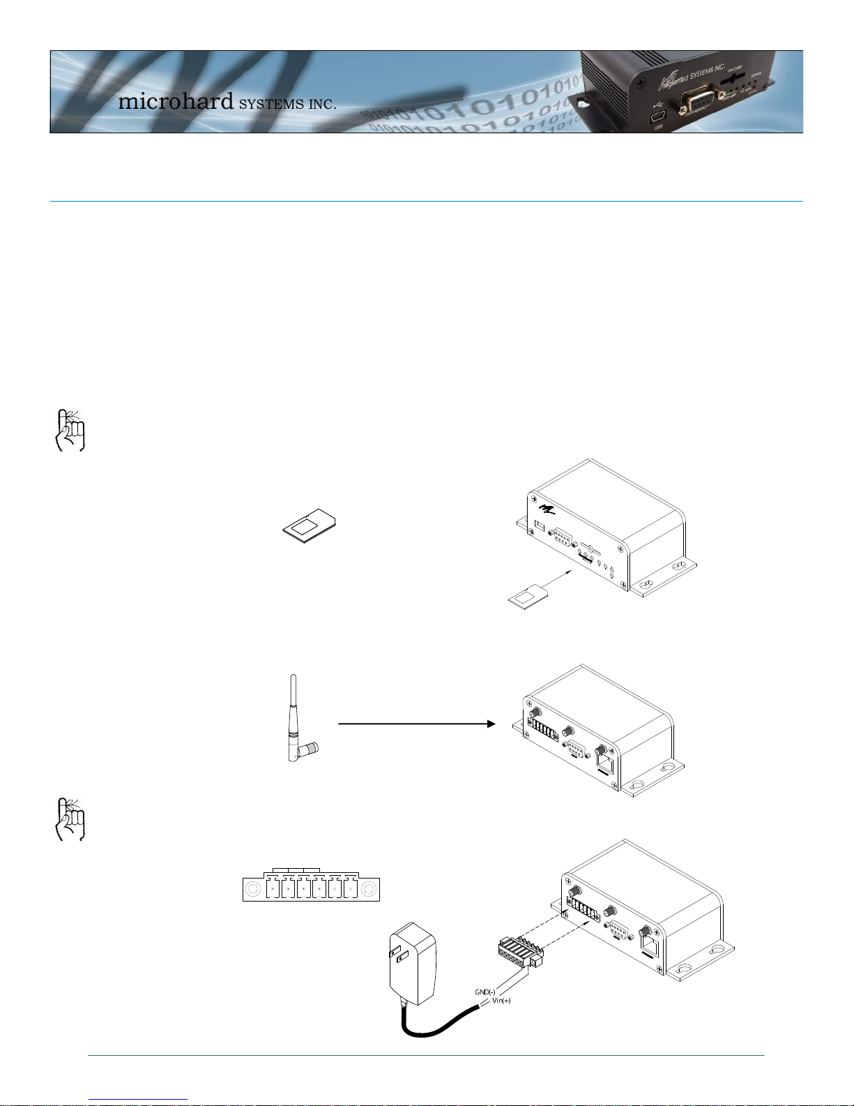
2.0 Quick Start
This QUICK START guide will walk you through the setup and process required to
access the WebUI configuration window and to establish a basic wireless connection
to your carrier.
Note that the units arrive from the factory with the Local Network setting configured
as ‘Static’ (IP Address 192.168.0.1, Subnet Mask 255.255.255.0, and Gateway
192.168.0.1), in DHCP server mode. (This is for the Ethernet Adapter on the back
of the IPn3G unit.
2.1 Installing the SIM Card
Before the IPn3G can be used on a cellular network a valid SIM Card for your
Wireless Carrier must be installed. Insert the SIM Card into the slot as shown
To reset to factory
defaults, press and
hold the CFG button
for 8 seconds with the
IPn3G powered up.
The LED’s will flash
quickly and the IPn3G
will reboot with factory
defaults.
below.
SIM Card Slot
2.2 Getting Started
Connect the Antenna’s to the applicable ANTENNA jack’s of the IPn3G.
Connect the Phoenix-Type Connector to the power adapter as shown below and
apply power to the unit.
Use the MHS-supplied
power adapter or an
equivalent power
source.
© Microhard Systems Inc. 12
Main Antenna (SMA)
(GPS & Diversity not shown)
Page 13
2.0 Quick Start
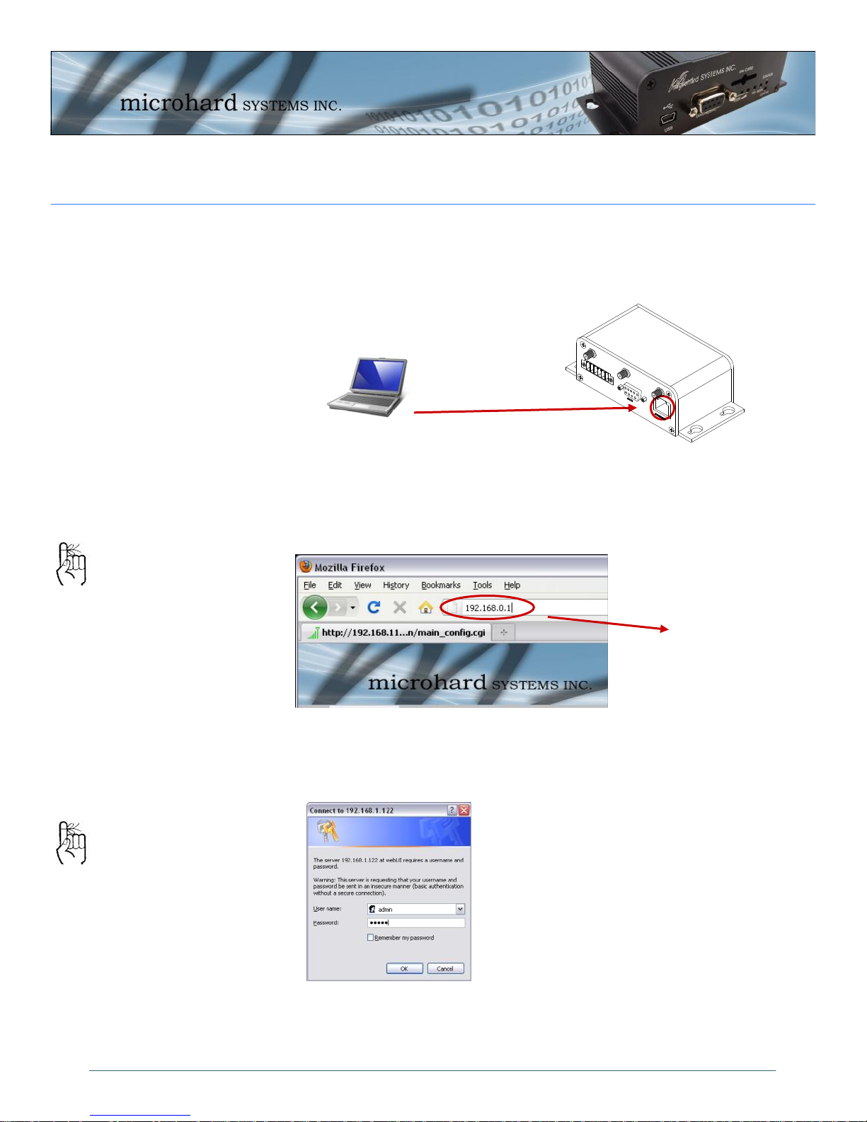
Connect A PC configured for DHCP directly to the ETHERNET port of the IPn3G,
using an Ethernet Cable. If the PC is configured for DHCP it will acquire a IP Address from the IPn3G.
Open a Browser Window and enter the IP address 192.168.0.1 into the address
bar.
The factory default
network settings:
IP: 192.168.0.1
Subnet: 255.255.255.0
Gateway: 192.168.0.1
The factory default login:
User name: admin
Subnet: admin
It is always a good idea to
change the default admin
login for future security.
The IPn3G will then ask for a Username and Password. Enter the factory de-
faults listed below.
192.168.0.1
The Factory default login:
User name: admin
Password: admin
© Microhard Systems Inc. 13
Page 14
2.0 Quick Start
Once successfully logged in, the System Summary Window will be displayed.
To establish basic wireless connectivity with your carrier, the information in the
Carrier > Config menu must be completed as provided by your carrier.
Carriers may require different
information to be filled out.
Contact them for specific connection information.
For SIM Cards issued with Dynamic IP addresses most carriers simply require the correct
APN. SIM Cards assigned Static
public IP address often require
a login details.
Carriers require the following
information:
Always Required:
Access Point Name (APN)
Some Carriers Require:
Authentication Type
User Name
Password
© Microhard Systems Inc. 14
Page 15
2.0 Quick Start
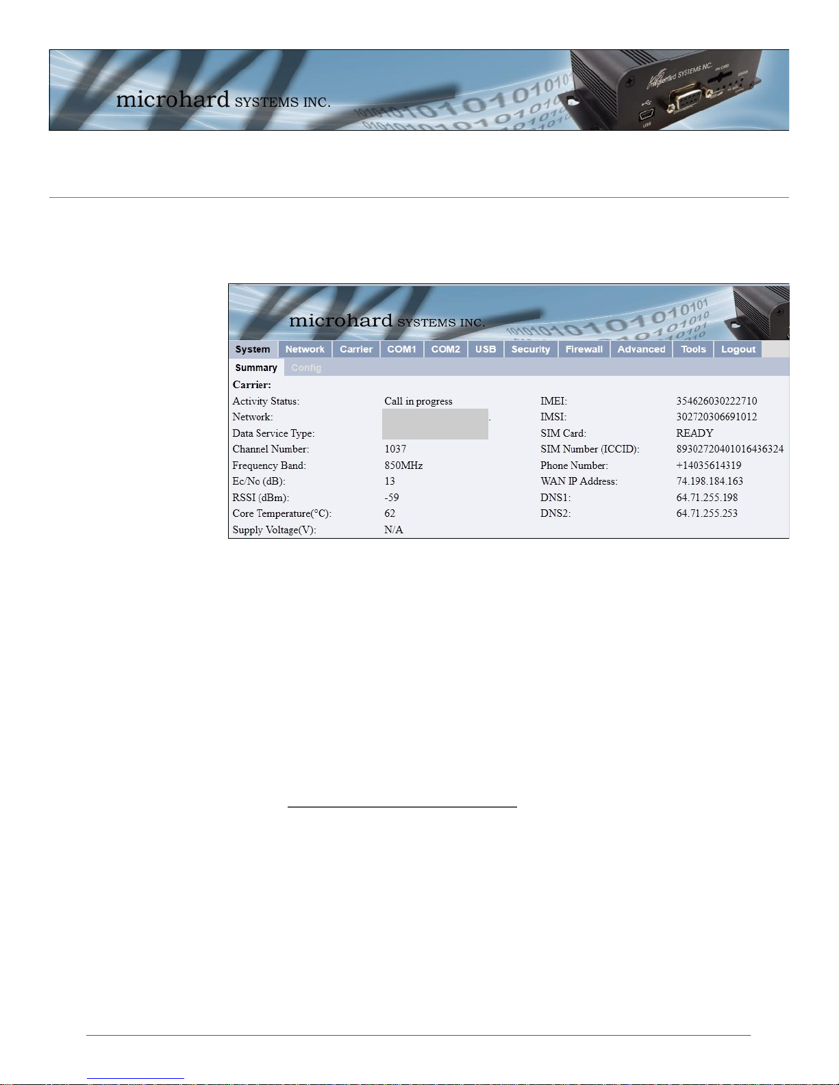
Verify connectivity with your Wireless Carrier by selecting Carrier > Statistics
or System > Summary. Your carriers name should appear next to the Network
entry and the Activity Status should read as: Call in progress
If you do not see “Call in Progress” you are not connected to or communicating
with your wireless carrier.
Check that the SIM card is installed correctly.
Verify that the proper antennas are installed correctly
Verify the APN assigned by the carrier.
Re-Enter the login details, if required by the carrier, to ensure any typing
You see “Call in Progress”, but no Internet Access. Check the WAN IP Address in
the Carrier > Statistics or System > Summary screens. If an IP Address is
not shown, check the APN and login details for errors.
Refer to Section 4.0 WebUI Configuration to configure serial ports, USB, or any
security or firewall features required on the IPn3G.
errors.
Carrier Name
Service Type
© Microhard Systems Inc. 15
Page 16
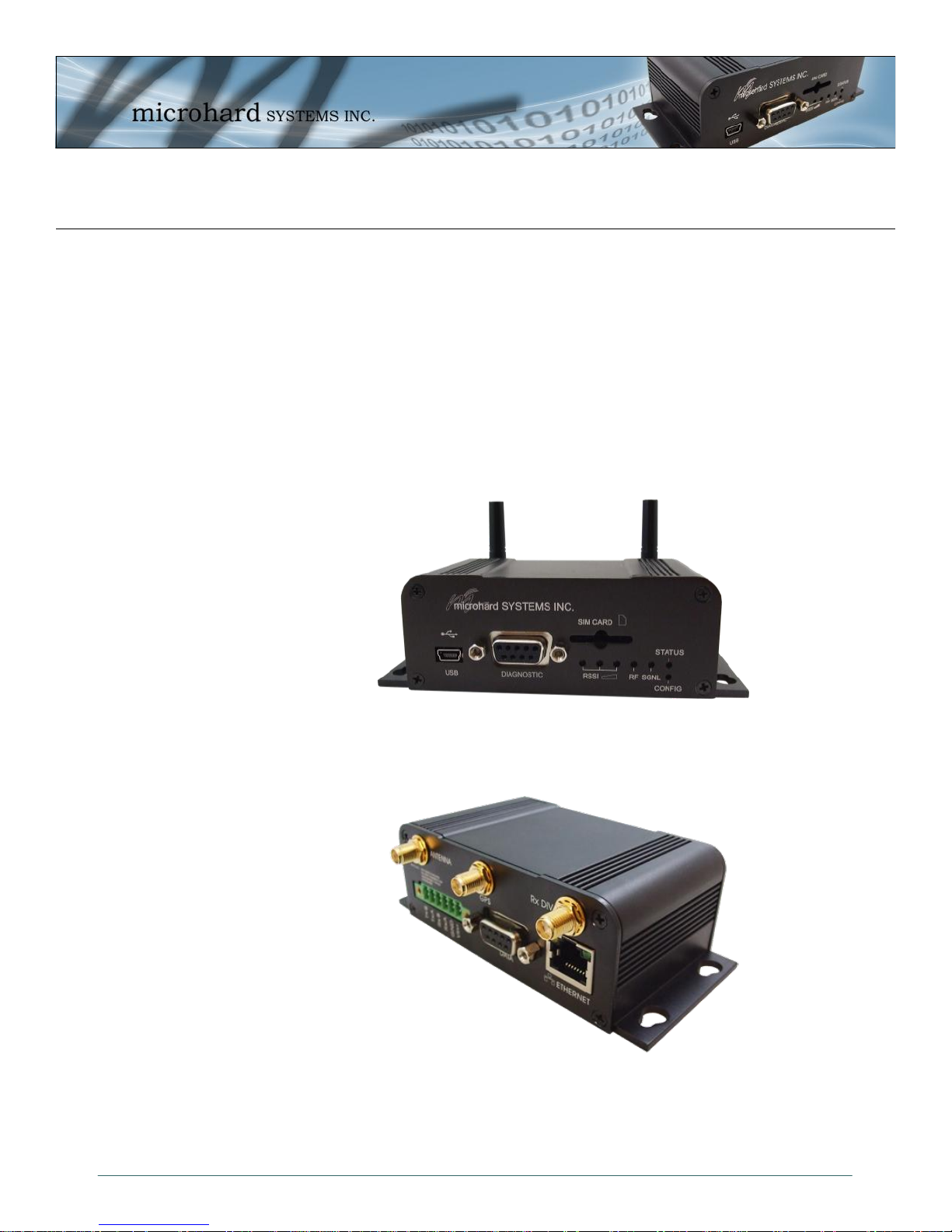
3.0 Hardware Description
3.1 IPn3G Hardware
The IPn3G provides a fully enclosed, stand alone modem, requiring only cabled connections.
The IPn3G can be used on a table top like surface, or using the mounting holes provided can be
mounted anywhere for a permanent solution.
Power
Data (Serial) Interface
Ethernet Interface
USB Interface
LED Indicators
Antenna’s (Main, GPS, Diversity)
Image 3-1: IPn3G Front View
Image 3-2: IPn3G Back View
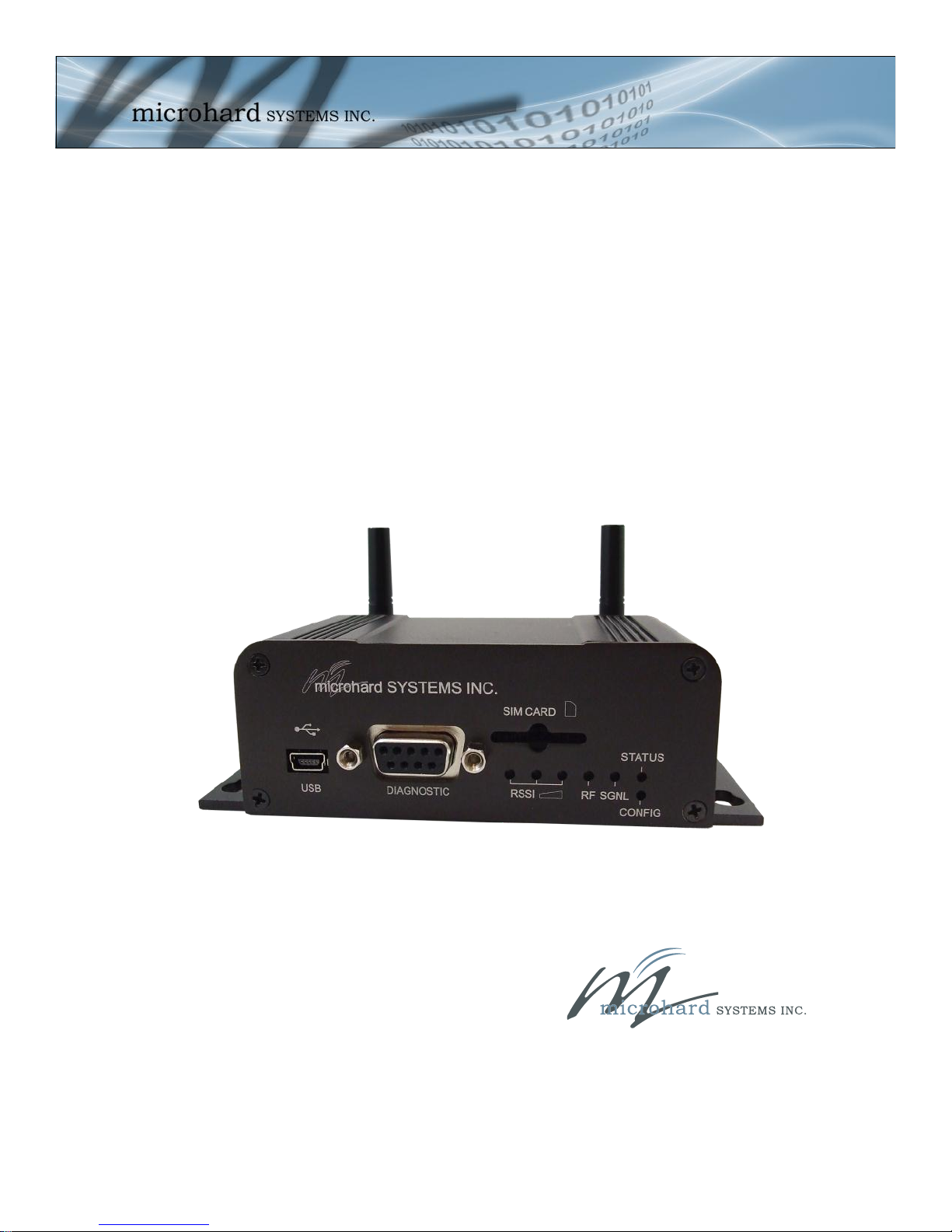
© Microhard Systems Inc. 16
Page 17
IPn3G-ENC
Top View
microhard SYSTEMS INC.
SIM CARD
RSSI
DIAGNOSTIC
RF SGNL
STATUS
CONFIG
USB
RS485/422
Vin+
GND
RxA
RxB
TxA
TxB
DATA
ETHERNET
ANTENNA
GPS
RX DIV
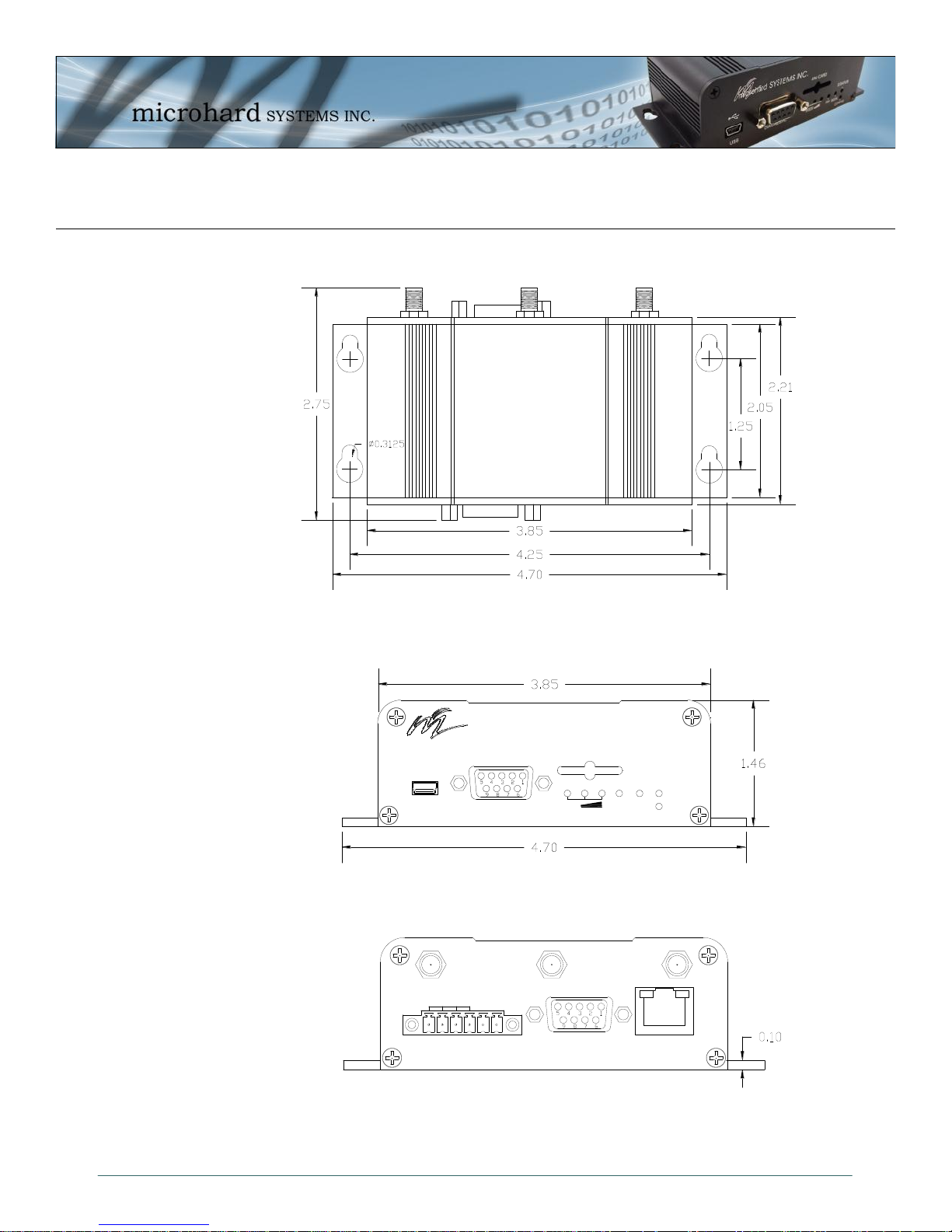
3.0 Hardware Description
3.1.1 IPn3G Mechanical Drawings
Drawing 3-1: IPn3G Top View
© Microhard Systems Inc. 17
Drawing 3-2: IPn3G Front View
Image 3-3: IPn3G Back View
Notes: The dimension unit is inches.
Page 18
microhard SYSTEMS INC.
SIM CARD
RSSI
DIAGNOSTIC
RF SGNL
STATUS
CONFIG
USB
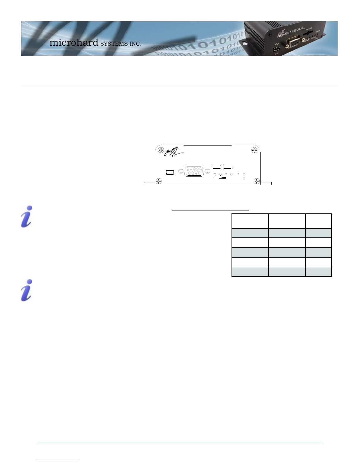
3.0 Hardware Description
3.1.2 Connectors and Indicators
3.1.2.1 Front
On the front of the IPn3G is the USB port, DIAGNOSTIC port, CONFIG Button, RSSI, STATUS, RF and
SGNL LED’s as described below:
The USB port can be used for: (See Section 4.1.7 USB Configuration)
Console Port
Data Mode
Windows USB driver
downloads are available
to registered users
from:
microhardcorp.com/
support
The Diagnostic port (RS232) is used for:
NDIS Mode
AT Command Interface at 115.2kbps and
HyperTerminal (or equivalent).
User data (RS232 - RxD, TxD, and SG)
Digital I/O—Input Pin 7, Output Pin 8
CONFIG (Button) - Holding this button depressed while powering-up the IPn3G will boot the unit into
FLASH FILE SYSTEM RECOVERY mode. The default IP address for system recovery (only - not for nor-
Digital I/O is only
available and has been
implemented on units
shipped after June 1,
2012
mal access to the unit) is static: 192.168.1.39.
If the unit has been powered-up for some time (>1 minute), depressing the CFG Button for 8 seconds will
result in FACTORY DEFAULTS being restored, including a static IP address of 192.168.0.1. This IP address is useable in a Web Browser for accessing the Web User Interface.
RF LED (Red) - When connected to a 2G/EDGE or 3G-WCDMA Network, the RF LED indicates
a transmission burst. When connected to a 3G/HSPA Network the LED has no function.
SGNL LED (Green) - When illuminated, the SGNL LED indicates that the modem is connected and syn-
chronized with a wireless carrier.
Receive Signal Strength Indicator (RSSI) (3x Green) - As the received signal strength increases,
starting with the furthest left, the number of active RSSI LEDs increases. If the measured signal strength is
less than –110dBm no LED’s will be illuminated. If the signal is greater than –105dBm, 1 LED will be on, 100dBm equals 2 LED’s, and any signal greater than –95dBm will show all 3 RSSI LED’s to be ON.
STATUS LED (Red) - Upon initial application of power the STATUS LED will be illuminated for approxi-
© Microhard Systems Inc. 18
mately 20 seconds, after which time it will being to blink slowly (loading) for an additional 25 seconds, then
stay ON ‗solid‘ (indicating it has achieved its specific operational status).
Drawing 3-4: IPn3G Front View
Table 3-1: Diagnostic Port RS232 Pin Assignment
Signal
Name
RXD 2 O
TXD 3 I
SG 5
Digital In 7 I
Digital Out 8 O
PIN
#
Input or
Output
Page 19
RS485/422
TxB -
TxA -
RxB -
RxA -
GND -
Vin+ -
RS485/422
Vin+
GND
RxA
RxB
TxA
TxB
DATA
ETHERNET
ANTENNA
GPS
RX DIV
3.0 Hardware Description
3.1.2 Connectors and Indicators
3.1.2.2 Rear
On the back of the IPn3G is the Data port, RS485/422 interface, as well as the power connections. The
unit also has the SMA(F) connectors for the Main (TX/RX), GPS and the Diversity (RX) antenna’s.
The DATA (RS232 Port (DCE)) on the rear
of the circuit board is used for:
RS232 serial data (300-921kbps) when
in DATA MODE, or
for configuring the modem when in
COMMAND MODE.
The RS422/485 Port is used to interface the Nano
Development Board to a DTE with the same
interface type. Either the RS232 or RS422/485 interface is
used for data traffic.
Vin+/Vin– is used to power the unit. The input Voltage
range is 7-30 Vdc.
Caution: Using a
power supply that
does not provide
proper voltage may
damage the modem.
© Microhard Systems Inc. 19
Drawing 3-5: IPn3G Rear View
Green Conn.
Table 3-3: Data RS422/485 / Vin Pin Assignment
Name Data Port Input or
DCD 1 O
RXD 2 O
TXD 3 I
DTR 4 I
SG 5
DSR 6 O
RTS 7 I
CTS 8 O
RING 9 O
Table 3-2: Data RS232 Pin Assignment
Name Input or
Pin No.
6 TxB (D+) O
5 TxA (D-) O
4 RxB (R+) I
3 RxA (R-) I
2 Vin -
1 Vin + I
Output
Output
Page 20
4.0 WebUI Configuration
The Web User Interface (WebUI) is a browser based configuration method that allows a user a
graphical interface to configure, test and troubleshoot a IPn3G unit. Any standard web browser
can be used and no additional software is required. Using the Web User Interface a user can:
Remotely or locally configure a IPn3G unit, including:
Network settings
Radio configuration
Serial Port configuration
Security
USB
Retrieve unit revisions
Update system firmware
Much more...
In this section, all aspects of the Web Browser Interface, presented menus, and available
configuration options will be discussed.
© Microhard Systems Inc. 20
Page 21
4.0 WebUI Configuration
4.1 Logon Window
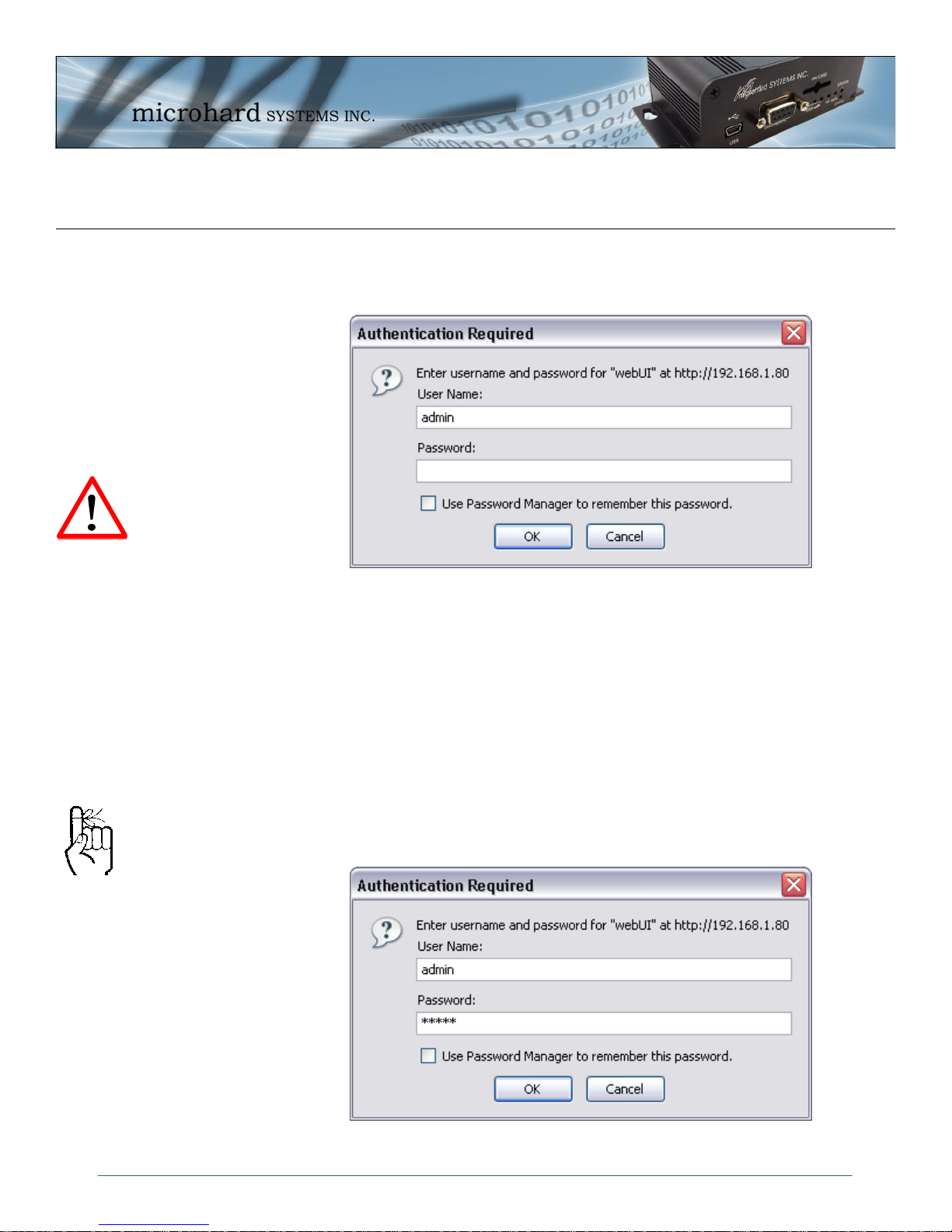
Upon successfully accessing the IPn3G using a Web Browser, the Logon window will appear.
For security, do not
allow the web browser
to remember the User
Name or Password.
It is advisable to
change the login
Password (see Section
4.1.8.1). Do not
FORGET the new
password as it cannot
be recovered.
The factory default User Name is: admin
The default password is: admin
Note that the password is case sensitive. It may be changed (discussed further along in this
section), but once changed, if forgotten, may not be recovered.
When entered, the password appears as ’dots’ as shown in the image below. This display
format prohibits others from viewing the password.
The ‘Remember my password’ checkbox may be selected for purposes of convenience,
however it is recommended to ensure it is deselected - particularly once the unit is deployed in
the field - for one primary reason: security.
Image 4-1: Logon Window
© Microhard Systems Inc. 21
Image 4-2: Logon Window With Password Input
Page 22
4.0 WebUI Configuration
4.2 System
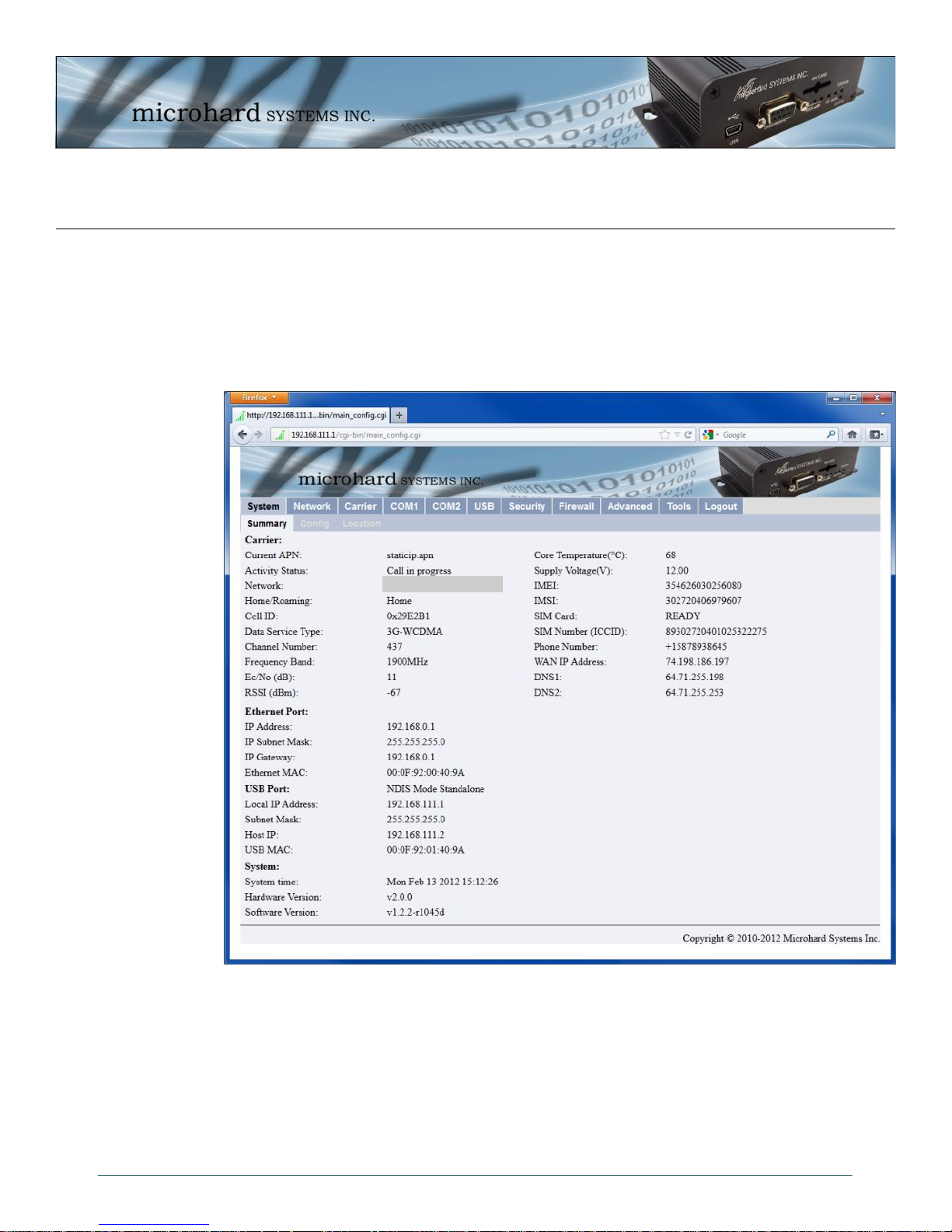
4.2.1 System > Summary
The System Summary window displays an overview of the current IPn3G configuration. When
initially logging into the unit, this will be the first window displayed, allowing a user to quickly
identify configuration information.
Carrier Name
Image 4-3: System Summary Window
The System Summary window displays information about the wireless carrier as well as local
network, USB and System information:
Carrier: Activity Status, Network, WAN IP, Phone Number, SIM Card info etc
Ethernet Port: Local Ethernet Port information of rear RJ45 Connector.
USB Port: USB Port information, NDIS IP Address etc.
System: Hardware and Software versions and System time.
© Microhard Systems Inc. 22
Page 23
4.0 WebUI Configuration
4.2.2 System > Config
The System Config submenu allows the configuration of the Radio Description, the Time and
Date, including NTP time server parameters. As well as the Console and Wireless Traffic
timeouts.
Image 4-4: System Config Window
Radio Description
The Radio Description is simply a convenient identifier for a specific
IPn3G, e.g. Pump Station 5, 123 Main Street, etc. This feature is
most welcome when accessing units remotely: a convenient cross-
reference for the unit’s IP address. This ‘name’ appears in all menu
windows. It has no bearing on the unit’s operation.
Values (Characters)
Default is model-dependent
up to 30 characters
Date (yyyy-mm-dd)
The calendar date may be entered in this field. Note that the
entered value is lost should the IPn3G lose power for some reason.
© Microhard Systems Inc. 23
Values (2010-08-05)
valid date values, where
yyyy = 4-digit year
mm = 2-digit month
dd = 2-digit day
Page 24

4.0 WebUI Configuration
NTP may be used to
synchronize the time in
the IPn3G within a
network to a reference
time source.
The calendar date may be entered in this field. Note that the
entered value is lost should the IPn3G lose power for some reason.
The Timezone field allows you to set the time zone in the IPn3G.
Select the time zone from the dropdown list that matches your
location. Time zones are sorted by UTC (+/-) offset.
Note that if NTP Server Status is ENABLED, the ‘Synchronize with
NTP Server’ soft button on the System Configuration menu will be
available for use.
Leave as DISABLED (default) if a server is not available.
IP address or domain name for NTP server (on local LAN or
website (provided that Internet access is available)) is to be entered
in this field if the NTP Server Status is configured as ENABLED.
Time (hh:mm:ss)
Values (11:27:28)
hh = 2-digit hours
mm = 2-digit minutes
ss = 2-digit seconds
Timezone
Values (List)
Select the applicable
time zone from the
dropdown list.
NTP Time Synchronize
Values (Selection)
Disable
Enable
NTP Server (IP/Name)
Values (0.0.0.0)
valid NTP server IP
address or ‘name’
This value determines when the console connection (made via
COM2) will timeout after becoming inactive.
The Wireless Traffic Timeout will reset the unit if there has been no
RF activity in the configured time. 0 = Disabled (default)
Enabled by default, when the CONFIG button on the front of the
IPn3G is held down for 10s while the unit is powered up, the unit
will reset and all settings will be reset to factory defaults. When
disabled the unit will reset, but the settings will not be overwritten.
© Microhard Systems Inc. 24
Console Timeout (s)
Values (seconds)
60
0-65535
Wireless Traffic Timeout (s)
Values (seconds)
600
300-65535
System Default Button
Values (Selection)
Enable
Disable
Page 25
4.0 WebUI Configuration
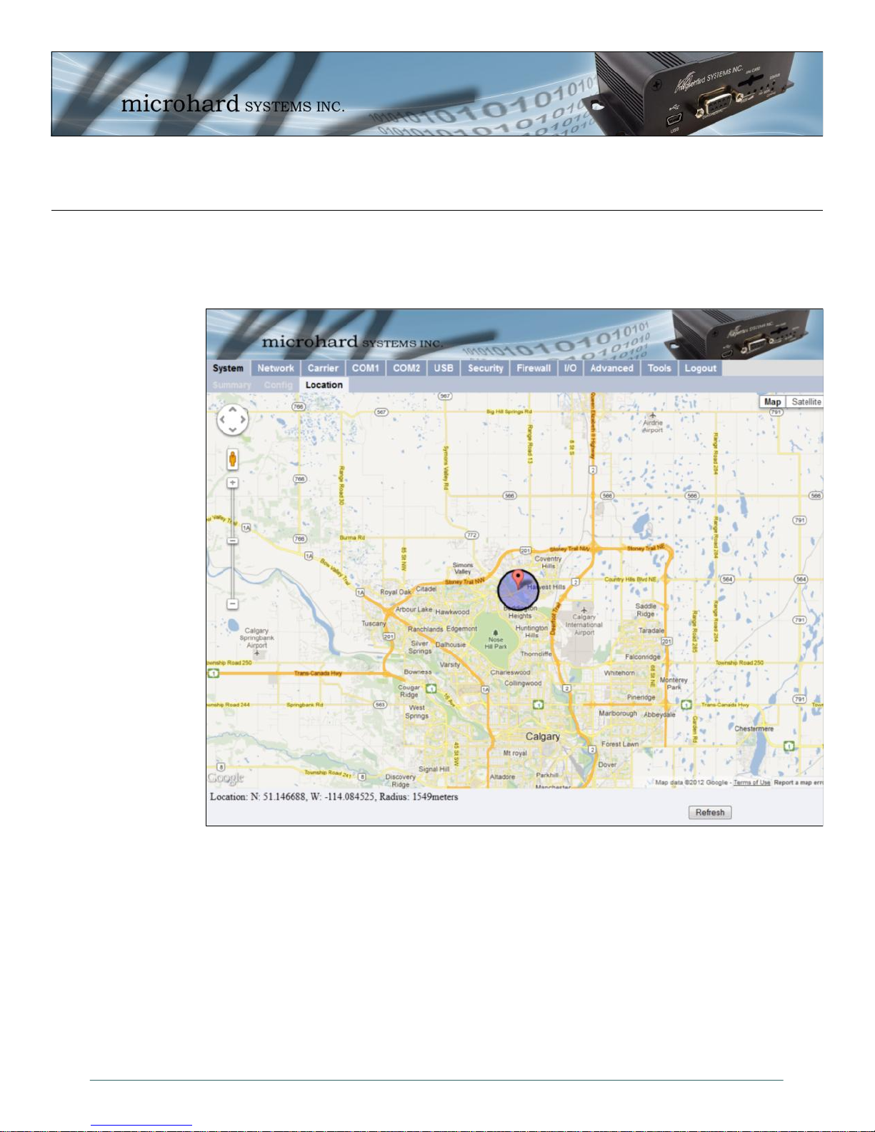
4.2.3 System > Location
The Location menu uses the Cell Tower ID that the unit is currently connect to to approximate
the general location of the IPn3G.
© Microhard Systems Inc. 25
Image 4-5: System > Location
Page 26
4.0 WebUI Configuration
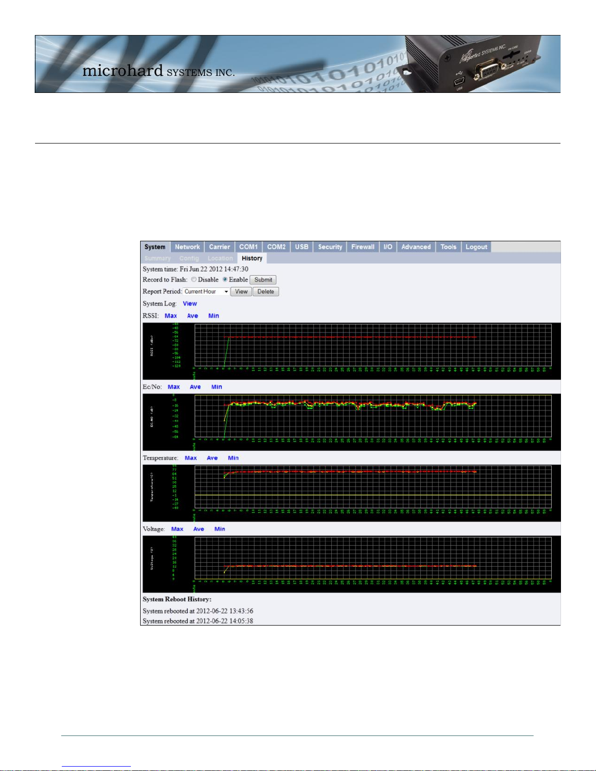
4.2.4 System > History
The History menu shows a graphical history of RSSI, Ec/No, Temperature, and Voltage of the
Cellular module. Data for the current hour, as well as a specific 24 hour period of a calendar
date. Clicking the Max, Ave and Min links will show the raw data used to plots the points on the
graphs. The data points are optionally stored in non-volatile (flash) memory, so data is saved
even when the IPn3G is restarted or power is lost.
The System Log link will dump the entire unit system log, this is a raw dump of the background
processes of the IPn3G, this is useful for troubleshooting or debugging issues.
The System Reboot History shows the time and date that the unit has restarted. Currently over
100 events can be stored and viewed.
© Microhard Systems Inc. 26
Image 4-5a: System > Location
Page 27
4.0 WebUI Configuration
4.3 Network
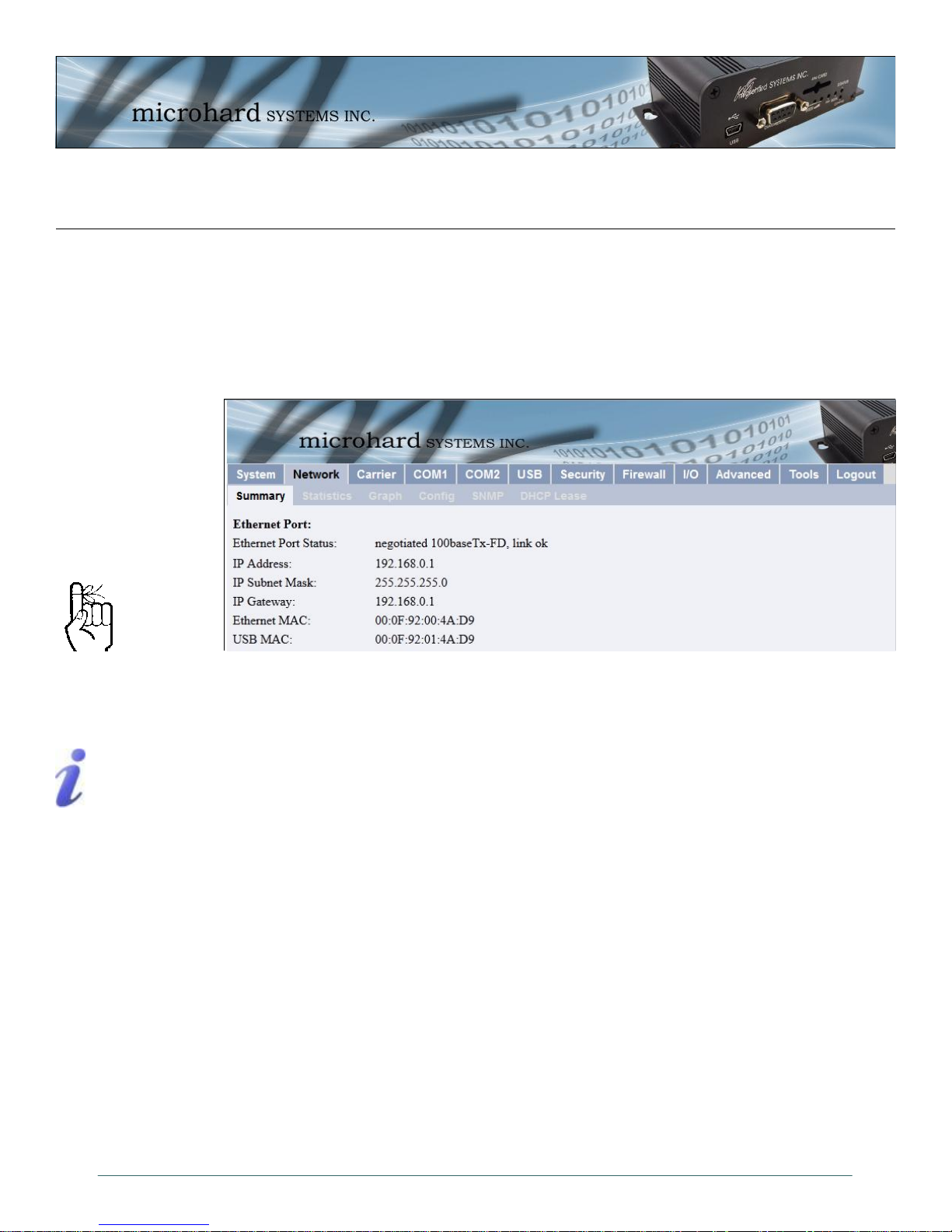
4.3.1 Network > Summary
The Network > Summary tab gives an overview of the configuration of the Ethernet port on the
IPn3G. This port is the RJ45 port located on the back of the IPn3G.
Within any IP network,
each device must have its
own unique IP address.
A SUBNET MASK is a bit
mask that separates the
network and host (device)
portions of an IP address.
The ‘unmasked’ portion
leaves available the
information required to
identify the various
devices on the subnet.
Image 4-6: Network Configuration , Local IP Configuration Submenu
Ethernet Port Status: The Ethernet port status shows the type and status of the local Ethernet
Link.
IP Address: This is the currently configured logical IP address of the IPn3G. This IP
address must be set statically in the Network > Config tab. This is generally
set to a Private IP address for a local network.
IP Subnet Mask: The IP Subnet Mask is the current Subnet Mask being used by the unit to
define the subnet and host address of the IPn3G.
IP Gateway: The IP Gateway sets the default gateway for traffic leaving the IPn3G.
Ethenet MAC: This is the physical MAC address of the RJ45 Ethernet Port of the back of
the IPn3G
USB MAC: For quick reference, this is the physical MAC address of the USB port on the
front of the IPn3G, when it is configured as a NDIS Ethernet Interface. See
the USB section for more information.
© Microhard Systems Inc. 27
Page 28
4.0 WebUI Configuration
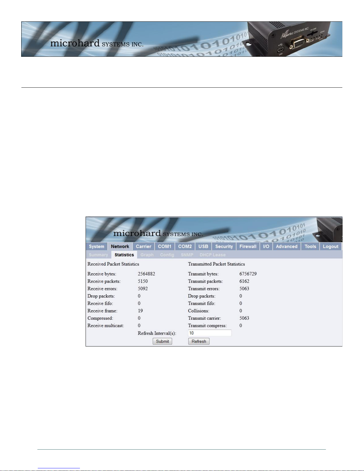
4.3.2 Network > Statistics
The Network > Statistics tab displays a variety of parameters which apply to the traffic through,
and status of, the physical Ethernet port (hardware interface) on the rear of the IPn3G.
Received and Transmitted information are applicable to the local data traffic into and out of the
IPn3G, respectively. Errors which are counted include alignment, frame check sequence (FCS),
frame too long, and internal MAC. The dropped packet count could increment if, for example,
the network layer was too busy to accept the data.
The FIFO errors are related to interface-specific hardware.
Collisions occur on all Ethernet networks being that Ethernet operates as a logical bus. The
amount of collisions is typically related to the number of devices on the attached network and
the amount of data being moved.
The Transmit Carrier count relates to carrier sense errors.
© Microhard Systems Inc. 28
Image 4-7: Network Statistics
Page 29
4.0 WebUI Configuration
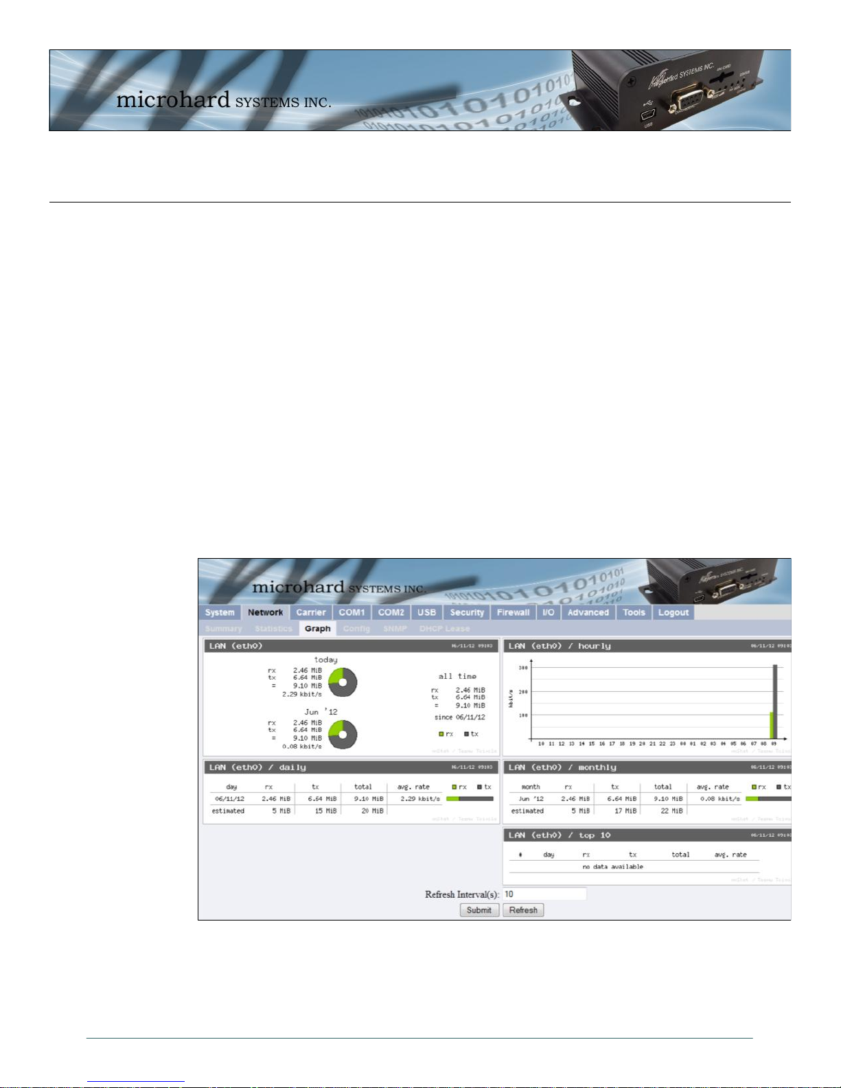
4.3.3 Network > Graph
The Network > Graph tab displays a graphical display of the Ethernet Traffic on the Ethernet
interface of the IPn3G.
LAN (eth0) Shows an overview of all data sent or received by the IPn3G at the
LAN (eth0) / hourly Shows the traffic volumes (TX = green, RX = grey) at hourly intervals
LAN (eth0) / daily Shows the total data received and transmitted for the day, as well as
LAN (eth0) / monthly Shows the total data received and transmitted for the current month,
LAN (eth0) / Top 10 Show the top 10 days with the most data sent or received.
physical Ethernet port on the rear of the unit. A summary of the data of
the current day and the current month is shown.
during the current 24 hour period. This could be useful to see when the
most or least amount of traffic is present.
the average rate of data.
as well as the average rate of data.
© Microhard Systems Inc. 29
Image 4-8: Network Graph
Page 30
4.0 WebUI Configuration
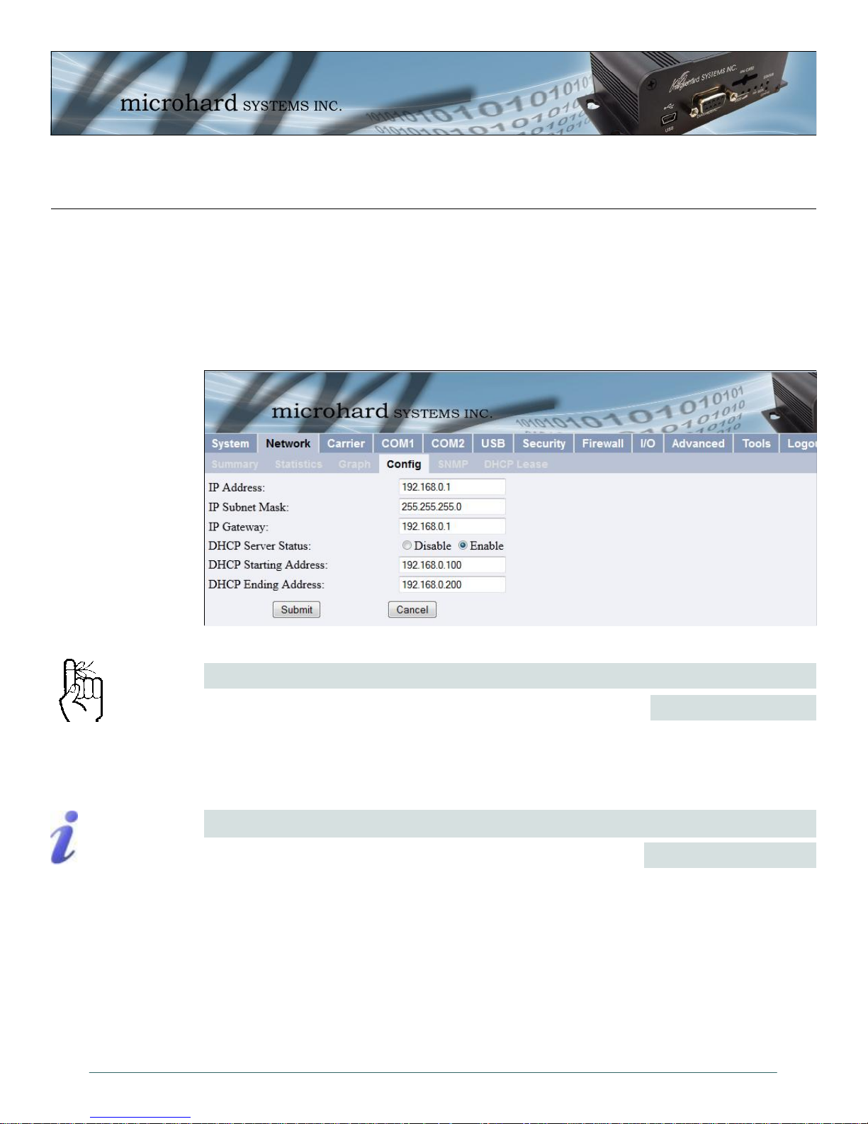
4.3.4 Network > Config
The Network > Config tab allows the configuration of the Ethernet port on the IPn3G (Rear
RJ45). This port is configured as static port and must be configured by the user if the default
values are not to be used. By default this port acts as a simple DHCP server, allowing the
IPn3G to assign IP addresses and enable communication to attached devices. Caution must be
taken not to connect the IPn3G to an existing network where a DHCP server may already be
running.
Within any IP network,
each device must have its
own unique IP address.
A SUBNET MASK is a bit
mask that separates the
network and host (device)
portions of an IP address.
The ‘unmasked’ portion
leaves available the
information required to
identify the various
devices on the subnet.
Image 4-9: Network Configuration , Local IP Configuration Submenu
Enter a valid IP Address. The default IP address for the Ethernet
Port on the IPn3G is 192.168.0.1.
For a small private network with IP addresses appearing similar to
192.168.1.xx (Class C address), the standard 255.255.255.0
subnet mask may be applicable.
IP Address
Values
192.168.0.1
valid value is specific to
the network
IP Subnet Mask
Values
255.255.255.0
valid value is specific to
the network
© Microhard Systems Inc. 30
Page 31

4.0 WebUI Configuration
IP Gateway
A GATEWAY is a point
within a network that acts
as an entrance to another
network.
In typical networks, a
router acts as a gateway.
Prior to enabling this
service, verify that there
are no other devices either wired (e.g. LAN) or
wireless (e.g. another
unit) with an active DHCP
SERVER service.
(The Server issues IP
address information at the
request of a DHCP Client,
which receives the
information.)
If the IPn3G units are integrated into a network which has a defined
gateway, then, as with other hosts on the network, this gateway’s IP
address will be entered into this field.
A simple way of looking at what the gateway value should be is: If
a device has a packet of data is does not know where to send, send
it to the gateway. If necessary - and applicable - the gateway can
forward the packet onwards to another network.
Choose to enable or disabled the DHCP Server service. Devices on
the network, which are intended to receive IP address information
from this DHCP Server, must have their local IP settings set for
‘DHCP’ (as opposed to ‘static’). The default is Enabled.
DHCP Starting Address
This is the starting (‘lower boundary’) IP address of the range of IP
addresses (also known as ’IP address pool’) to be issued by the
DHCP Server to the applicable devices on the network.
This is the ending (‘upper boundary’) IP address of the range of IP
addresses to be issued by the DHCP Server to the applicable
devices on the network.
Values
192.168.0.1
valid value is specific to
the network
DHCP Server Status
Values
Disable
Enable
Values
192.168.0.100
IP address as per above
DHCP Ending Address
Values
192.168.0.200
IP address as per above
© Microhard Systems Inc. 31
Page 32

4.0 WebUI Configuration
4.3.5 Network > SNMP
The IPn3G may be configured to operate as a Simple Network Management Protocol (SNMP)
agent.
Network management is most important in larger networks, so as to be able to manage resources and measure performance.
SNMP: Simple Network
Management Protocol
provides a method of
managing network
devices from a single PC
running network
management software.
Managed networked
devices are referred to as
SNMP agents.
SNMP may be used in several ways:
configure remote devices
monitor network performance
detect faults
audit network usage
detect authentication failures
A SNMP management system (a PC running SNMP management software) is required for this
service to operate. An SNMP MIB Browser can be also be used to provision the IPn3G, these
utilities are not supplied by Microhard Systems, but many free and premium types of browsers
are available on the market. This system must have full access to the IPn3G network. Communications is in the form of queries (information requested by the management system) or traps
(information initiated at, and provided by, the SNMP agent in response to predefined events).
Objects specific to the IPn3G are hosted under private enterprise number 21703.
An object is a variable in the device and is defined by a Management Information Database
(MIB). Both the management system and the device have a copy of the MIB. The MIB in the
management system provides for identification and processing of the information sent by a device (either responses to queries or device-sourced traps). The MIB in the device relates subroutine addresses to objects in order to read data from, or write data to, variables in the device. Contact Microhard Systems Inc, for the most recent MIB file.
An SNMPv1 agent accepts commands to retrieve an object, retrieve the next object, set and object to a specified value, send a value in response to a received command, and send a value in
response to an event (trap).
SNMPv2c adds to the above the ability to retrieve a large number of objects in response to a single request.
SNMPv3 adds strong security features including encryption; a shared password key is utilized.
Secure device monitoring over the Internet is possible. In addition to the commands noted as
supported above, there is a command to synchronize with a remote management station.
Custom MIBs can be obtained by contacting Microhard Systems Inc. Appendix D: SNMP MIB
Sample contains the first few pages of the IPn3G MIB to be used as a reference The MIB file can
change when new features are added, so it is best to contact us for the complete and latest MIB
file for the IPn3G.
© Microhard Systems Inc. 32
Page 33

4.0 WebUI Configuration
Image 4-10: Network > SNMP
If disabled, no SNMP service is provided from the device. Enabled,
the device - now an SNMP agent - can support SNMPv1, v2, & v3.
Read Only Community Name
Effectively a plain-text password mechanism used to weakly
authenticate SNMP queries. Being part of the community allows
the SNMP agent to process SNMPv1 and SNMPv2c requests. This
community name has only READ priority.
Read Write Community Name
Effectively a plain-text password mechanism used to weakly
authenticate SNMP queries. Being part of the community allows
the SNMP agent to process SNMPv1 and SNMPv2c requests. This
community name has only READ/WRITE priority.
Defines the user name for SNMPv3.
SNMP Operation Mode
Values
Disable / V1&V2&V3
Values (char string)
public
Values (char string)
private
SNMP V3 User Name
Values (char string)
© Microhard Systems Inc. 33
V3user
Page 34

4.0 WebUI Configuration
Defines accessibility of SNMPv3; select either Read Only or Read/
Write priority. If Read Only is selected, the SNMPv3 user may only
read information; if Read Write is selected, the SNMPv3 user may
read and write (set) variables.
V3 User Read Write Limit
V3 User Authentication Level
Defines SNMPv3 user’s authentication level.
NoAuthNoPriv: No authentication, no encryption.
AuthNoPriv: Authentication, no encryption.
AuthPriv: Authentication, encrpytion.
V3 Authentication Password
SNMPv3 user’s authentication password. Only valid when V3 User
Authentication Level set to AuthNoPriv or AuthPriv (see above).
V3 Authentication Password
SNMPv3 user’s encryption password. Only valid when V3 User
Authentication Level set to AuthPriv (see above).
Values
Read Only
Read Write
Values
NoAuthNoPriv
AuthNoPriv
AuthPriv
Values (char string)
00000000
Values (char string)
00000000
Select which version of trap will be sent should a
failure or alarm condition occur.
If enabled, an authentication failure trap will be generated upon
authentication failure.
The community name which may receive traps.
Defines a host IP address where traps will be sent to (e.g. SNMP
management system PC IP address).
Values
V1 Traps
V2 Traps
V3 Traps
SNMP Trap Version
V1&V2 Traps
V1&V2&V3 Traps
Auth Failure Traps
Values
Disable / Enable
Trap Community Name
Values (char string)
TrapUser
Trap Manage Host IP
Values
0.0.0.0
© Microhard Systems Inc. 34
Page 35

4.0 WebUI Configuration
4.3.6 Network > DHCP Lease
The Network > DHCP Lease tab show a summary of IP Address’s assigned by the IPn3G’s
DHCP server. As seen below the MAC address, IP Address, Name and the amount of time
remaining on the DHCP lease is shown.
Image 4-11: Network Configuration , Local IP Configuration Submenu
© Microhard Systems Inc. 35
Page 36

4.0 WebUI Configuration
4.4 Carrier
4.4.1 Carrier > Statistics
The Carrier Statistics window provides information related to the Wireless Carrier portion of the
IPn3G. A variety of information can be found here, such as Activity Status, Network (Name of
Wireless Carrier connected) , Data Service Type(2G/3G etc), Frequency band, Phone Number
etc.
Not all statistics parameters displayed are applicable.
The Received and Transmitted bytes and packets indicate the respective amount of data which
has been moved through the radio.
The Error counts reflect those having occurred on the wireless link.
© Microhard Systems Inc. 36
Image 4-12: Carrier Configuration Menu
Page 37

4.0 WebUI Configuration
4.4.2 Carrier > Graph
The Carrier > Graph tab displays a graphical display of the Carrier Traffic on the Wireless
interface of the IPn3G.
WAN (ppp0) Shows an overview of all data sent or received by the IPn3G on the
WAN (ppp0) / hourly Shows the traffic volumes (TX = green, RX = grey) at hourly intervals
WAN (ppp0) / daily Shows the total data received and transmitted for the day, as well as
WAN (ppp0) / monthly Shows the total data received and transmitted for the current month,
WAN (ppp0) / Top 10 Show the top 10 days with the most data sent or received.
Wireless portion of the unit. A summary of the data of the current day
and the current month is shown.
during the current 24 hour period. This could be useful to see when the
most or least amount of traffic is present.
the average rate of data.
as well as the average rate of data.
© Microhard Systems Inc. 37
Image 4-13: Carrier Graph
Page 38

4.0 WebUI Configuration
4.4.3 Carrier Configuration
The parameters within the Carrier Configuration menu must be input properly; they are the most
basic requirement required by your cellular provider for network connectivity.
This option allows for the automatic detection of available carriers,
the manual selection of detected carriers, or the fixed selection of
entering a carriers ID. Manual and Fixed are commonly used when
the IPn3G is Roaming and it is desirable to control which carrier the
unit connects to.
In Manual Carrier mode, select the desired carrier from the list of
available carriers. In fixed mode, enter the Carrier ID.
© Microhard Systems Inc. 38
Image 4-14: Carrier Config
Carriers
Values (selection)
Automatic
Manual
Fixed
Carrier ID
Values
Varies
Page 39

4.0 WebUI Configuration
Network Data Mode
When set to Automatic the modem will automatically decide on the
best signal to connect to, in some cases this may be 2G. When set
to 3G Priority, the modem will continually try to connect to 3G.
Access Point Name (APN)
The (Access Point Name) APN is required and assigned by the
wireless carrier. A Carrier will have different APNs for different
service types (Static vs Dynamic etc).
It is possible to have a Pin number associated with a SIM card that
is required to use the SIM card on a device. If the installed SIM card
has been set up with a SIM Pin, enter the number here.
NAT (Network Address Translation)
When NAT is enabled internal addresses are not visible to external
networks. When disabled the router does not perform any address
translation on the packets passing through it.
Values (selection)
Automatic / 3G Priority
Values (String)
Carrier dependant
SIM Pin
Values (String)
Carrier dependant
Values (selection)
Disable / Enable
PPP Status
This option allows the operation of PPP.
Values (selection)
Disable / Enable
IP-Passthrough
IP pass-through allows the WAN IP address to be assigned to the
device connected to the rear Ethernet port on the IPn3G. In this
mode the IPn3G is transparent and forwards all traffic to the device
connected to the Ethernet port. The WebUI port (Default HTTP
Port:80), this port is retained for remote management of the IPn3G.
This port can be changed to a different port under the Security >
Access Menu. It is recommended to reboot the IPn3G after
changing these settings.
Values (selection)
Disable / Ethernet
Dial-on-Demand
If disabled, the modem will always remain connected. The default is
Disabled.
© Microhard Systems Inc. 39
Values (selection)
Disable / Enable
Page 40

4.0 WebUI Configuration
The maximum amount of time to pass before modem will timeout.
The default is 0 seconds.
The maximum amount of time to wait for a connection The default
is 90 seconds.
The maximum amount of attempts to dial and establish a
connection. The default is 0, which means that there is no
maximum and the modem will keep trying indefinitely.
Sets the authentication type required to negotiate with peer.
PAP - Password Authentication Protocol.
CHAP - Challenge Handshake Authentication Protocol.
Idle Time Out
Values (seconds)
0-65535
Connect Time Out
Values (seconds)
0-65535
Dialing Max Retries
Values
0-100
Authentication Type
Values (selection)
NoAuth
pap
chap
pap-chap
User Name
User Name as required for authentication to remote peer. May not
be required for dynamically assigned IP addresses from the
wireless carrier. Usually required for static IP addresses.
Values (char string)
Carrier/peer dependant
Password
Password as required for authentication to remote peer. May not be
required for dynamically assigned IP addresses from the wireless
carrier. Usually required for static IP addresses.
Values (char string)
Carrier/peer dependant
Dial Number
Sets the number to be dialed. Carrier dependant, the default
number is *99***1#
Values (String)
*99***1#
Static IP Address
In some cases the Static IP address must be entered in this field if
assigned by a wireless carrier. In most cases the IP will be read
from the SIM card and this field should be left at the default value.
© Microhard Systems Inc. 40
Values
0.0.0.0
Page 41

4.0 WebUI Configuration
Use Remote DNS
Enabled by default, the IPn3G, will use the DNS server as specified
automatically by the service provider.
Sets the modems connect string if required by the carrier.
Image 4-15a: Carrier Configuration Menu, DDNS Config...
Values (Selection)
Disable / Enable
Connect String
Values (String)
CONNECT
Initialization 1 - 4
The modem can have up to 4 initialization strings.
Image 4-15b: Carrier Configuration Menu, DDNS Config...
Values (String)
Init-string
DDNS Status
This selection allows the use of a Dynamic Domain Name Server
(DDNS), for the IPn3G.
© Microhard Systems Inc. 41
Values (Selection)
Disable / Enable
Page 42

4.0 WebUI Configuration
Service Name
Unless a carrier issues a Static IP address, it may be desirable to
use a dynamic DNS service to track dynamic IP changes and
automatically update DNS services. This allows the use of a
constant resolvable host name for the IPn3G.
This is a list of supported Dynamic DNS service providers. Free and
premium services are offered, contact the specific providers for
more information.
This is the host or domain name for the IPn3G as assigned by the
DDNS provider.
Enter a valid user name for the DDNS service selected above.
Values (Selection)
dyndns.org
changeip.com
zoneedit.com
no-ip.com
noip.com
freedns.afraid.org
dnsmax.com
thatip.com
Domain
Values
user.dyndns.org
User Name
Values
username
Password
Enter a valid password for the user name of the DDNS service
selected above.
Image 4-16: Carrier Configuration Menu, ICMP Keep Alive Check...
Values
username
ICMP Keep Alive Check
This selection allows the use of a ICMP Keep Alive Check for the
IPn3G. The default is disabled.
© Microhard Systems Inc. 42
Values (selection)
Disable / Enable
Page 43

4.0 WebUI Configuration
HostName
A user can set up a reachable host (IP or domain) for the unit to
ping periodically to keep the WAN connection alive (Wireless
Carrier) in case the carrier shuts it down due to lack of activity.
PING frequency is defined by the Interval.
The Interval value determines the frequency, or how often, the
IPn3G will send out PING messages to the Host.
The Count field is the maximum number of PING errors such as
“Host unreachable” the IPn3G will attempt before the unit will reboot
itself to attempt to correct connection issues. If set to zero (0), the
unit will never reboot itself.
Values (IP Address)
IP Address or Name of
host for ICMP PING.
Interval
Values (seconds)
30
Count
Values
10
© Microhard Systems Inc. 43
Page 44

4.0 WebUI Configuration
4.5 COM1/COM2
4.5.1 COM1/2 > Statistics
This window displays information related to the serial interfaces of the IPn3G.
COM1/2 Port Status
Enabled by default. (IF COM2 is disabled it is available as a ‘Console’ port.)
COM1/2 Connect As
Display of chosen protocol with respect to serial gateway function.
COM1/2 Connect Status
If port is enabled and there is data traffic, this will display ‘Active’.
The other displayed parameters are not all applicable. Of most use are the transmitted and
received bytes/packets: these will indicate if data is coming into and out of the COM ports.
© Microhard Systems Inc. 44
Image 4-17: COM1 Configuration Menu
Page 45

4.0 WebUI Configuration
4.5.2 COM1 and COM2 Configuration
The menus ’COM1 > Config’ and ’COM2 > Config’ are used to configure the serial device
server for the serial communications ports:
COM1 (DATA), the rear DE9 connector on the IPn3G, and
COM2 (DIAGNOSTIC), the front DE9 connector.
Serial device data may be brought into a LAN network through TCP, UDP, or multicast; it may
also exit the IPn3G network on another IPn3G ’s serial port.
COM1 is a full-featured RS232 interface dedicated to serial data traffic. It supports hardware
handshaking. By default, this port is enabled.
COM2 is, by default, disabled. In this state, it may be used as the console port for the text user
interface. Enabled, it becomes another serial port for data traffic. It is a 3-wire (TxD, RxD, and
SG) interface and does not support hardware handshaking.
For brevity, only COM1 is fully detailed in this section; the relative limitations of COM2 are noted
where applicable.
© Microhard Systems Inc. 45
Image 4-18: COM1 Configuration Menu
Page 46

4.0 WebUI Configuration
Port Status
Note: Most PCs do not
readily support serial
communications greater
than 115200bps.
Select operational status of port. Enabled by default.
*COM2 is Disabled by default. If COM2 is Enabled and there is a
desire to switch it back to Disabled (console mode) via the serial
connection to it, the escape sequence of ‘+++’ may be entered at
the Data Baud Rate for which the port is configured.
Determines which (rear of unit) serial interface shall be used to
connect to external devices: RS232, RS485, or RS422. This
option applies only to COM1 / DATA. When an interface other than
RS232 is selected, the DE9 port will be inactive.
The serial baud rate is the rate at which the modem
is to communicate with the attached local
asynchronous device.
*COM2 data baud rate maximum is 115200bps.
Values (bits per second (bps))
921600
460800
230400
115200
57600
38400
28800
19200
Values
Enable
Disable
Channel Mode
Values
RS232 / RS485 / RS422
Data Baud Rate
14400
9600
7200
4800
3600
2400
1200
600
300
Data Format
This setting determines the format of the data on the serial port.
The default is 8 data bits, No parity, and 1 Stop bit.
Values
8N1
8N2
8E1
8O1
7N1
7N2
Flow Control
Flow control may be used to enhance the reliability
of serial data communications, particularly at higher
baud rates. If the attached device does not support
hardware handshaking, leave this setting at the
default value of ‘None’.
Software flow control
(XON/XOFF) is not
supported.
© Microhard Systems Inc. 46
When CTS Framing is selected, the IPn3G uses
the CTS signal to gate the output data on the serial
port. Figure 3A below illustrates the timing of
framed output data.
*COM2 does not support Flow Control.
Values
None / Hardware / CTS Framing
Drawing 4A: CTS Output Data Framing
7E1
7O1
7E2
7O2
Page 47

4.0 WebUI Configuration
Pre-Data Delay (ms)
Refer to Drawing 3A.
*COM2 does not support this function.
Values (ms)
100
Post-Data Delay (ms)
Refer to Drawing 3A.
*COM2 does not support this function.
Values (ms)
100
Data Mode
This setting defines the serial output data framing. In Transparent
mode (default), the received data will be output promptly from the
IPn3G. When set to Seamless, the serial port server will add a gap
between data frames to comply with the MODBUS protocol for
example.
Values
Seamless
Transparent
Character Timeout
In Seamless mode (see Data Mode), this setting determines when
the serial server will consider the recently-received incoming data
as being ready to transmit. As per the MODBUS standard, frames
will be marked as ‘bad’ if the time gap between frames is greater
than 1.5 characters, but less than the Character Timeout value.
The serial server also uses this parameter to determine the time gap inserted between frames.
It is measured in ‘characters’ and related to baud rate.
Example: If the baud rate is 9600bps, it takes approximately 1ms to move one character. With
the Character Timeout set to 4, the timeout period is 4ms. When the calculated time is less than
3.5ms, the serial server will set the character timeout to a minimum value of 3.5ms. If the baud
rate is greater than 19200bps, the minimum character timeout is internally set to 750us
(microseconds).
Values
characters
4
Defines the buffer size that the serial server will use to receive data
from the serial port. When the server detects that the Character
Timeout criteria has been met, or the buffer is full, it packetizes the
received frame and transmits it.
This setting effects the Quality of Service (QoS) associated with the
data traffic on the specific COM port.
© Microhard Systems Inc. 47
Maximum Packet Size
Values (Bytes)
1024
Priority
Values
Normal
Medium
High
Page 48

4.0 WebUI Configuration
Image 4-18a: COM1 Data Logging
Data Logging Status
Data Logging on the COM ports allows for the actual serial port
data to be sent to a remote host. This data can be in the Raw form
or converted to Hex before it is sent.
Select Tx&Rx to log data to/from the serial port. Select Tx to log
data that is being transmitted from the serial port, and Rx to log
data being received at the serial port.
Enter the IP Address of the where the logging data is to be sent.
Generally this is a PC listening on the specified UDP port.
Enter the UDP port of the IP Address where the data is to be sent.
Values (selection)
Disable
Raw
Hex
Logging Direction
Values (selection)
Tx&Rx
Tx
Rx
Logging Host IP
Values (IP Address)
0.0.0.0
Logging Host Port
Values (UDP Port)
30001
© Microhard Systems Inc. 48
Page 49

4.0 WebUI Configuration
The protocol selected in
the IP Protocol Config
field will determine which
configuration options
appear in the remainder
of the COMn
Configuration Menu.
UDP: User Datagram
Protocol does not provide
sequencing information
for the packets sent nor
does it establish a
’connection’ (‘handshakin
g’) and is therefore most
suited to communicating
small packets of data.
TCP: Transmission
Control Protocol in
contrast to UDP does
provide sequencing
information and is
connection-oriented; a
more reliable protocol,
particularly when large
amounts of data are being
communicated.
Requires more bandwidth
than UDP.
This setting determines which protocol the serial server will use to transmit serial port data over
the IP Series network.
TCP Client: When TCP Client is selected and data is received on its serial port, the IPn3G
IP Protocol Config
takes the initiative to find and connect to a remote TCP server. The TCP session is terminated
by this same unit when the data exchange session is completed and the connection timeout has
expired. If a TCP connection cannot be established, the serial port data is discarded.
Remote Server Address
IP address of a TCP server which is ready to accept serial port data through a TCP
connection. For example, this server may reside on a LAN network server.
Default: 0.0.0.0
Remote Server Port
A TCP port which the remote server listens to, awaiting a session connection
request from the TCP Client. Once the session is established, the serial port data is
communicated from the Client to the Server.
Default: 20001
Outgoing Connection Timeout
This parameter determines when the IPn3G will terminate the TCP connection if the
connection is in an idle state (i.e. no data traffic on the serial port).
Default: 60 (seconds)
TCP Server: In this mode, the IPn3G will not INITIATE a session, rather, it will wait for a Client
to request a session of it (it’s being the Server—it ‘serves’ a Client). The unit will ‘listen’ on a
specific TCP port. If a session is established, data will flow from the Client to the Server, and, if
present, from the Server to the Client. If a session is not established, both Client-side serial
data, and Server-side serial data , if present, will be discarded.
Local Listening Port
The TCP port which the Server listens to. It allows a TCP connection to be created
by a TCP Client to carry serial port data.
Default: 20001
Incoming Connection Timeout
Established when the TCP Server will terminate the TCP connection is the
connection is in an idle state.
Default: 300 (seconds)
TCP Client/Server: In this mode, the IPn3G will be a combined TCP Client and Server,
meaning that it can both initiate and serve TCP connection (session) requests. Refer to the
TCP Client and TCP Server descriptions and settings described previously as all information,
combined, is applicable to this mode.
© Microhard Systems Inc. 49
Page 50

4.0 WebUI Configuration
A UDP or TCP port is an
application end-point.
The IP address identifies
the device and, as an
extension of the IP
address, the port
essentially ‘fine tunes’
where the data is to go
‘within the device’.
Be careful to select a port
number that is not
predetermined to be
associated with another
application type, e.g.
HTTP uses port 80.
Multicast is a one-tomany transmission of
data over an IP network.
It is an efficient method of
transmitting the same
data to many recipients.
The recipients must me
members of the specific
multicast group.
TTL: Time to Live is the
number of hops a packet
can travel before being
discarded.
In the context of multicast,
a TTL value of 1 restricts
the range of the packet to
the same subnet.
IP Protocol Config (continued)
UDP Point-to-Point: In this configuration the IPn3G will send serial data to a specifically-
defined point, using UDP packets. This same IPn3G will accept UDP packets from that same
point.
Remote IP Address
IP address of distant device to which UDP packets are sent when data received at
Default: 0.0.0.0
Remote Port
UDP port of distant device mentioned above.
Default: 20001
Listening Port
UDP port which the IP Series listens to (monitors). UDP packets received on this
Default: 20001
UDP Point-to-Multipoint (P): This mode is configured on an IPn3G which is to send multicast
UDP packets; typically, the MASTER in the IPn3G network.
Multicast IP Address
A valid multicast address this unit uses to send multicast UDP packets upon
Default: 224.1.1.1
Multicast Port
A UDP port that this IPn3G will send UDP packets to. The Multipoint (MP - see the
Default: 20001
Listening Port
The UDP port that this unit receives incoming data on from multiple remote units.
Default: 20011
Time to Live
Time to live for the multicast packets.
Default: 1 (hop)
UDP Point-to-Multipoint (MP): This protocol is selected on the units which are to receive
multicast UDP packets, typically the Remote units. See the previous description of UDP Point-to
-Multipoint (P).
Remote IP Address
serial port.
port are forwarded to the unit’s serial port.
receiving data from the serial port. The default value is a good example of a valid
multicast address.
UDP Point-to-Multipoint (MP) description) stations should be configured to listen to
this point in order to receive multicast packets from this IPn3G.
The IP address of a distant device (IP Series or, for example, a PC) to which
the unit sends UDP packets of data received on the serial port. Most often this
is the IP address of the Master IP Series.
Default: 0.0.0.0
© Microhard Systems Inc. 50
Page 51

4.0 WebUI Configuration
In a Point-to-Multipoint
(PMP) network topology
which is to utilize UDP
multicast, typically the
MASTER would be
configured as ’(P)’ (the
POINT) and the
REMOTES would be
configured as ’(MP)’ (the
MULTIPOINTS).
Remote Port
Multicast IP Address
Multicast Port
UDP Multipoint-to-Multipoint
Multicast IP Address
A valid multicast address the unit will use to send multicast UDP packets upon
Default: 224.1.1.1
Multicast Port
UDP port that the packets are sent to. Multipoint stations should be configured to
Default: 20011
Time to Live
Time to live for the multicast packets.
Default: 1 (hop)
Listening Multicast IP Address
A valid multicast address the unit is to listen to receive multicast UDP packets sent
Default: 224.1.1.1
Listening Multicast Port
UDP port that the unit will listen to for multicast UDP packets sent by another UDP
The UDP port associated with the Remote IP Address (above). In the case of
this ‘Remote’ being the Master IPn3G, the value in this field should match the
Listening Port of the Master (see UDP Point-to-Multipoint (P)).
Default: 20011
A valid MULTICAST address that this unit will use to receive multicast UDP
packets sent by a UDP Point-to-Multipoint (P) unit. Note that the default value
for this field matches the default Multicast IP Address of the UDP Point-toMultipoint (P) configuration described on the previous page.
Default: 224.1.1.1
The UDP port that this unit will use, along with the Multicast IP Address detailed
above, to receive the multicast UDP packets sent by the UDP Point-toMultipoint (P) unit.
Default: 20001
receiving them at its serial port.
listen to this port in order to receive multicast packets.
by another UDP Multipoint-to-Multipoint unit.
Multipoint-to-Multipoint unit.
Default: 20011
IP Protocol Config (continued)
© Microhard Systems Inc. 51
Page 52

4.0 WebUI Configuration
SMTP: Simple Mail
Transport Protocol is a
protocol used to transfer
mail across an IP
network.
IP Protocol Config (continued)
SMTP Client: If the IPn3G network has Internet access, this protocol may be used to send the
data received on the serial port (COM1), in a selectable format (see Transfer Mode (below)), to
an e-mail addressee. Both the SMTP Server and the e-mail addressee must be ‘reachable’ for
his feature to function. Note: COM2 does not support this mode.
Mail Subject
Enter a suitable ‘e-mail subject’ (e-mail heading).
Default: COM1 Message
Mail Server (IP/Name)
Username / Password
Mail Recipient
A valid e-mail address for the intended addressee, entered in the proper format.
Default: host@
Message Max Size
Maximum size for the e-mail message.
Default: 1024
Timeout (s)
How long the unit will wait to gather data from the serial port before sending an e-
Default: 10
Transfer Mode
Select how the data received on COM1 is to be sent to the email addressee.
Default: Text
PPP: COM1 can be configured as a PPP server for a serial connection with a PC or other
device. The attached PC could then use a dedicated serial (WindowsXP - dialup/modem) type
PPP connection to access the network resources of the IPn3G. Note: COM2 does not support
this mode.
PPP Local IP
Enter the local PPP IP Address, the IP Address of the IPn3G COM1 Port.
Default: 192.168.0.1
PPP Host IP
PPP Idle Timeout(s)
Enter the desired PPP Idle Timeout in seconds.
IP address or ‘Name’ of SMTP (Mail) Server.
Default: 0.0.0.0
The username/password of the email account being used, if authentication is
required for outgoing email.
Default: varies/varies
mail message; data will be sent immediately upon reaching Message Max Size.
Options are: Text, Attached File, Hex Code.
Enter the PPP Host IP here. This is the IP of the PC or attached device.
Default: 192.168.0.99
Default: 30
© Microhard Systems Inc. 52
Page 53

4.0 WebUI Configuration
IP Protocol Config (continued)
SMS Transparent Mode: Serial data from the COM1 port can be send to one or multiple
destinations via SMS text messaging. SMS messages received by the IPn3G can also be sent
to the COM1 port.
Message Max Size
Enter the maximum message size. Once the number of characters has been
reached the IPn3G will package the data up and send it as a SMS message to the
number(s) specified. [1….160]. The character timeout can be used to send
messages more frequently by detecting a pause in the incoming data.
Default: 160
Reply Timeout(s)
Enter the PPP Host IP here.
Default: 10
Access Control
By selecting Anonymous, the IPn3G will accept a SMS message from any number.
If Control Phone List is selected, only messages from the numbers in the Access
Control List will be accepted.
Default: Anonymous
Read SMS Control
Select Keep in SIM Card to save incoming SMS messages in the SIM card, select
Delete to delete messages once they have been output to serial port.
Default: Keep in SIM Card
Access Control Phone List
Messages can be sent to up to five (5) numbers, also, this list can be used to filter
incoming SMS messages (See Access Control)
Default: None
© Microhard Systems Inc. 53
Page 54

4.0 WebUI Configuration
SMS AT Mode: When set to SMS AT Mode, the serial port accepts the SMS AT subset of the
AT Command Set. Only SMS AT Commands are available. For more detailed information about
specific commands, refer to the Section 5: AT Commands. The following commands are
available on the COM1 serial port:
AT+CMGR - Read Message
AT+CMGL - List Message
AT+CMGD - Delete Message
AT+CMGS - Send SM to Network
AT+CGMI - Request Manufacturer ID
AT+CGMM - Request Model ID
AT+CGMR - Request Revision
AT+CSQ - Signal Strength
AT+MMGR - Read Message (Does not change Status)
AT+MMGL - List Message (Does not change Status)
AT+CMFG - Message Format
AT+CCLK - Read System Date and Time
AT+CSCA - Service Center Address
AT+CREG - Network Registration Status
AT+CNMI - New Message Indications to Terminal
AT+CMTI - Stored SMS-DELIVER Indication Unsolicited Response
IP Protocol Config (continued)
Values
TCP Client
TCP Server
TCP Client/Server
UDP Point-to-Point
UDP Point-to-Multipoint (P)
UDP Point-to-Multipoint(MP)
UDP Multipoint-to-Multipoint
SMTP Client
PPP
SMS Transparent Mode
SMS AT Mode
© Microhard Systems Inc. 54
Page 55

4.0 WebUI Configuration
4.6 USB
4.6.1 USB > Statistics
This window displays information related to the USB port located on the front of the IPn3G.
USB Port Status
Displays the status of the USB Port.
Configure via USB Configuration menu.
USB Connect As
Display of chosen protocol with respect to serial gateway function.
Configure via USB Configuration menu.
USB Connect Status
If port is enabled and there is data traffic, this will display ‘Active’.
The other displayed parameters are not all applicable. Of most use are the transmitted and
received bytes/packets: these will indicate if data is coming into and out of the USB port.
© Microhard Systems Inc. 55
Image 4-19: USB > Statistics
Page 56

4.0 WebUI Configuration
4.6.2 USB > Config
The USB Device Port Mode allows a user to define the operation of the IPn3G ’s USB Port. The
port can be configured to be used as any one of the following:
Console Mode Provides support for the USB-to-Serial console port. In this case, Mini USB
port can be used as a USB-to-Serial console port for the text user interface.
Data Mode Provides support for the USB-to-Serial port. Mini USB port can be used as a
RS232 interface dedicated to serial data traffic.
NDIS Mode The USB port can be used as a network interface card. The IPn3G USB port is
configured by default in NDIS Standalone Ethernet Mode with a DHCP server
running in the background.
This means that a user can use the USB port communicate with the IPn3G via
Ethernet on the USB port of their PC’s.
Windows Drivers are available from the Support Desk on the Microhard Systems Inc website.
Please register and login into:
http://www.microhardcorp.com/support
© Microhard Systems Inc. 56
Image 4-20: USB Configuration Menu
Page 57

4.0 WebUI Configuration
Console Mode:
When the USB port in configured as Console Mode, the port acts as a console port.
Data Mode:
USB Data Mode is Disabled by default. If USB Data Mode is selected and there is a desire to
switch it back to Disabled (console mode) via the USB-to-Serial connection to it, the escape
sequence of '+++' may be entered at the Data Baud Rate for which the port is configured.
Image 4-21: USB Configuration Data Port
USB Device Port Mode
For more information about
any of the Data Port field
parameters refer to COM1/
COM2 Configuration.
© Microhard Systems Inc. 57
Values
Console Mode
Data Mode
NDIS Mode
Page 58

4.0 WebUI Configuration
NDIS Mode:
NDIS Standalone Mode is enabled by default. This setting will allow the USB port to act as a
network interface card.
USB Device Port Mode (Continued)
Image 4-22: USB NDIS Network Configuration
In standalone Mode the USB port will act as a separate NIC for the
IPn3G. In Bridge Mode the USB port wil use the same settings as
the rear ethernet port.
This is the IP Address of the USB NDIS adapter on the IPn3G. The
IPn3G acts as a DHCP server on this port and assigns an IP
address to connecting devices, i.e your PC.
Enter a valid subnet for the USB NIC.
Enter a valid host IP for the USB NIC.
NDIS Mode
Values (selection)
Bridge / Standalone
Local IP Address
Values
192.168.111.1
Subnet Mask
Values
255.255.255.0
Host IP
Values
192.168.111.2
© Microhard Systems Inc. 58
Page 59

4.0 WebUI Configuration
4.7 Security
4.7.1 Security > Password
Image 4-23: Security > Password Configuration Menu
To keep a system secure, the Administrator Password (which is prompted-for at the LogOn
window) should be modified rather than retaining the factory default value of ‘admin’.
The Upgrade Password protects the IPn3G from having firmware upgrade performed by an
unauthorized person. It is recommended that the default password be changed when the
system is deployed.
New Password/Repeat Password (admin)
Enter a new password for the Admin user. Repeat to ensure the
intended password was entered and that it was entered correctly.
Do not forget the admin password as, if lost, it cannot be recovered.
Values (char string)
admin
New Password/Repeat Password (upgrade)
Enter a new password for the Upgrade user. Repeat to ensure the
intended password was entered and that it was entered correctly.
Values (char string)
admin
© Microhard Systems Inc. 59
Page 60

4.0 WebUI Configuration
4.7.2 Security > Discovery
Image 4-24: Security Config. Menu, Discovery Service Config. Submenu
Telnet: A user command
which uses the TCP/IP
protocol to access a remote
device.
Format, from DOS prompt:
>telnet 192.168.1.50
where the IP address is that
of the target device.
If the above IP address is that
of an IPn3G accessible via
the network, the user will
arrive at the unit’s LogOn
window.
HTTP: HyperText Transfer
Protocol. The standard
protocol for transferring data
between a Web server and a
Web browser.
Allows, or disables use of the DiscoverIP utility. The discover IP
utility allows a user to scan a network for all available IPn3G units,
and displays the MAC and IP addresses as well as the unit
description. The port used for Discovery is 20077.
4.7.3 Security > Access
Image 4-25: Security Config. Menu, UI Access Config. Submenu
Discovery Service
Values (selection)
Disable
Discoverable
Changeable
User Interface (UI) Access Configuration allows the port
configuration of access services in the IPn3G, the default ports are
shown below.
SSH & HTTPS: Must be
specified at the time of
order and enabled via the
factory. Once enabled,
the options can be set.
It is also possible to disable the FTP Server, and the Local DNS
Server.
© Microhard Systems Inc. 60
Access
Values (selection)
Disable / Enable
Telnet (23)
HTTP (80)
SSH (22)
HTTPS (443)
Page 61

4.0 WebUI Configuration
4.7.4 Security > Authentication
There are two methods whereby a user may be authenticated for access to the IPn3G:
Local
Using the Admin or Upgrade access and associated passwords - the
authentication is done ‘locally’ within the IPn3G, and
RADIUS&Local
RADIUS authentication (using a specific user name and password supplied by
your RADIUS Server Administrator) - this authentication would be done
‘remotely’ by a RADIUS Server; if this authentication fails, proceed with Local
RADIUS: Remote
Authentication Dial In
User Service. An
authentication,
authorization, and
accounting protocol which
may be used in network
access applications.
A RADIUS server is used
to verifying that
information is correct.
authentication as per above.
Select the Authentication Mode: Local (default) or RADIUS&Local.
For the latter selection, RADIUS authentication must be attempted
FIRST; if unsuccessful, THEN Local authentication may be
attempted.
In this field, the IP address of the RADIUS server is to be entered if
RADIUS&Local has been selected as the Authorization Mode.
© Microhard Systems Inc. 61
Image 4-26: Security Config. Menu, Authentication Config. Submenu
Auth Mode
Values
Local
RADIUS&Local
RADIUS Server IP
Values
Valid RADIUS server IP
address
0.0.0.0
Page 62

4.0 WebUI Configuration
RADIUS Server Port
In this field, the applicable Port number for the RADIUS Server is to
be entered if RADIUS&Local has been selected as the
Authorization Mode.
Normally, a RADIUS Server uses Port 1812 for the authentication
function.
If the IP Series’ Authorization Mode has been set to
RADIUS&Local, obtain the RADIUS Secret for his particular client
from your RADIUS Server Administrator and enter it into this field,
and the following field. (You will also want to obtain the applicable
RADIUS User Name from your RADIUS Server Administrator.)
See above. Re-enter RADIUS Secret in this field.
Values
Applicable RADIUS
Server Port number
1812
RADIUS Secret
Values
Specific RADIUS Server
secret
nosecret
Repeat RADIUS Secret
Values
Specific RADIUS Server
secret
nosecret
RADIUS Timeout
Amount of time to wait for RADIUS authentication.
© Microhard Systems Inc. 62
Values
10
1-65535
seconds
Page 63

4.0 WebUI Configuration
4.8 Firewall
The Firewall Configuration is used to allow or disallow particular types of traffic access to and
from the network.
Image 4-27: Security Config. Menu, Firewall Configuration Submenu
When enabled, the firewall settings are in effect. When disabled,
none of the settings configured in the menu’s below have an effect,
the modem is “open”.
When Blocked the IPn3G will block at traffic on the WAN (Wireless
Carrier) unless specified otherwise in the Access Rules, MAC List,
IP List configurations. Access to ports 80 (HTTP) and 443 (HTTPSif enabled), is still available unless disabled in the Remote
Management option.
LAN to WAN Access Control
Allows or Blocks traffic from the LAN (Ethernet, USB NDIS)
accessing the WAN unless specified otherwise using the Access
Rules, MAC, and IP List configuration.
Allow remote management of the IPn3G on the WAN side using the
WebUI on port 80(HTTP), and 443 (HTTPS). If disabled, the
configuration can only be accessed from the LAN.
Firewall Status
Values
Disable / Enable
WAN Request
Values
Block / Allow
Values
Block / Allow
Remote Management
Values
Disable / Enable
© Microhard Systems Inc. 63
Page 64

4.0 WebUI Configuration
4.8.1 Firewall > Rules
Once the firewall is turned on, rules configuration can be used to define specific rules on how
local and remote devices access different ports and services. MAC List and IP List are used for
general access, and are applied before rules are processed.
The rule name is used to identify the created rule. Each rule must
have a unique name and up to 10 characters can be used.
The Action is used to define how the rule handles the connection
request.
ACCEPT will allow a connection, while REJECT (error) and DROP
(quietly dropped), will refuse connections.
This is configured based on how the WAN Request and LAN to
WAN Access Control are configured in the previous menus.
© Microhard Systems Inc. 64
Image 4-28: Firewall Configuration, Rules Config. Submenu
Rule Name
Values (10 Chars)
characters
Action
Values (selection)
ACCEPT
REJECT
DROP
Page 65

4.0 WebUI Configuration
Source Zone
Select the zone which is to be the source of the data traffic. WAN
applies to the wireless connection to the cellular carrier and the
LAN refers to local connections on the IPn3G (Ethernet, USB NDIS
etc)
If a valid IP/Network address is specified, the action will apply
against that address; otherwise, leaving the default value of
0.0.0.0/0 in this field results in the action applying to all source IP
addresses.
Select the zone which is the intended destination of the data traffic.
WAN applies to the wireless connection to the cellular carrier and
the LAN refers to local connections on the IPn3G (Ethernet, USB
NDIS etc)
If a valid IP/Network address is specified, the action will apply
against that address; otherwise, leaving the default value of
0.0.0.0/0 in this field results in the action applying to all source IP
addresses.
Values
WAN
LAN
none
Source IP
Values (IP Address)
0.0.0.0/0
Destination Zone
Values (selection)
WAN
LAN
none
Destination IP
Values (IP Address)
0.0.0.0/0
The protocol field defines the transport protocol type controlled by
the rule.
This field is used to define a port or service used in the rule (i.e.
Port 80 = HTTP which is generally a web server)
© Microhard Systems Inc. 65
Protocol
Values
TCP
UDP
ICMP
all
Destination Port
Values (port)
0
Page 66

4.0 WebUI Configuration
4.8.2 Firewall > Port Forwarding
Port forwarding can be used to forward traffic coming in from the WAN to a specific IP Address
and Port on the LAN. Port forwarding can be used in combination with other firewall features,
but the Firewall must be enabled for Port forwarding to be in effect.
Enable or disable DMZ Mode. DMZ can be used to forward all
traffic to the DMZ Server IP listed below.
Enter the IP address of the DMZ server on the LAN side of the
IPn3G.
Enter a exception port number that will NOT be forwarded to the
DMZ server IP. Usually a configuration or remote management port
that is excluded to retain external control of the IPn3G.
© Microhard Systems Inc. 66
Image 4-29: Firewall Configuration, Port Forwarding Config. Submenu
DMZ Mode
Values (selection)
Disable / Enable
DMZ Server IP
Values (IP Address)
192.168.100.100
Exception Port
Values (Port #)
443
Page 67

4.0 WebUI Configuration
Rule Name
This is simply a field where a convenient reference or description is
added to the rule. Each Forward must have a unique rule name and
can use up to 10 characters.
Enter the IP address of the intended internal (i.e. on LAN side of
IPn3G) server.
Target port number of internal server on the LAN IP entered above.
Select the type of transport protocol used. For example Telnet uses
TCP, SNMP uses UDP, etc.
Values (10 chars)
Forward
Internal Server IP
Values (IP Address)
192.168.2.1
Internal Port
Values (Port #)
3000
Protocol
Values
TCP
UDP
ICMP
all
External Port
Port number of incoming request (from WAN-side).
© Microhard Systems Inc. 67
Values (Port #)
2000
Page 68

4.0 WebUI Configuration
4.8.3 Firewall > MAC List
MAC List configuration can be used to control which physical LAN devices can access the ports
on the IPn3G, by restricting or allowing connections based on the MAC address. MAC List can
be used alone or in combination with LAN to WAN Access Control to provide secure access to
the physical ports of the IPn3G.
Image 4-30: Firewall Configuration, MAC List Config. Submenu
The Rule Name field is required to give the rule a convenient name
for reference. Each rule must have a unique name, up to 10
characters in length.
Specify the MAC Address to be added to the list. Must be entered
in the correct format as seen above.
The Action is used to define how the rule handles the connection
request.
ACCEPT will allow a connection, while REJECT (error) and DROP
(quietly dropped), will refuse connections.
Rule Name
Values (10 chars)
MAC_List
MAC Address
Values (MAC Address)
00:00:00:00:00:00
Action
Values (selection)
ACCEPT
DROP
REJECT
© Microhard Systems Inc. 68
Page 69

4.0 WebUI Configuration
4.8.4 Firewall > IP List
IP List configuration can be used to define who or what can access the IPn3G, by restricting or
allowing connections based on the IP Address/Subnet. Can be used alone or in combination
with WAN Request and LAN to Wan Access Control.
Image 4-31: Firewall Configuration, Blacklist Configuration Submenu
The Rule Name field is required to give the rule a convenient name
for reference. Each rule must have a unique name, up to 10
characters in length.
Specify the specific IP or Network address (With /subnet, for
example 192.168.0.0/24 will apply to all IP addresses in the
192.168.0.1 - 192.168.0.254 range (subnet /24 = 255.255.255.0).
Optional, enter a destination IP address to make the IP list more
specific. Leave as 0.0.0.0/0 to not use.
Enter the specific zone that the IP List will apply to, WAN
(Wireless), LAN (Ethernet, USB NDIS) or None (both).
Rule Name
Values (10 chars)
IP_List
Source Address
Values (IP Address)
0.0.0.0/0
Destination Address
Values (IP Address)
0.0.0.0/0
Select Zone
Values (Selection)
WAN / LAN / NONE
The Action is used to define how the rule handles the connection
request. ACCEPT will allow a connection, while REJECT (error)
and DROP (quietly dropped), will refuse connections.
© Microhard Systems Inc. 69
Action
Values (selection)
ACCEPT / DROP / REJECT
Page 70

4.0 WebUI Configuration
4.8.5 Firewall > Default
This menu provides a soft button which, when selected, will reset the firewall settings to factory
defaults. Once the button is pressed all configured firewall settings will immediately be reset to
factory defaults.
Image 4-32: Reset Firewall to Default
© Microhard Systems Inc. 70
Page 71

4.0 WebUI Configuration
4.9 I/O
4.9.1 Status
On the front diagnostics (COM2) port of the IPn3G (Units shipped after June 1, 2012), 2 pins
have been set aside to be used for Digital I/O. Pin 7 is used as an INPUT, and Pin 8, is used for
a OUTPUT. The status window shows the current status of these pins.
Image 4-33: I/O > Status
Diagnostics Port (DB9 - Female)
Pin 7 - INPUT
Pin 8 - OUTPUT
INPUT PINS
Pin 7 on the front diagnostics port of the IPn3G can be used to detect an input. Pin 7 has a
small wetting current (Vin) used to detect a contact closure, and prevent false readings by any
noise or intermittent signals, it has a threshold sensitivity of 1.8V.
OUTPUT PINS
Pin 8 on the diagnostics port of the IPn3G can be used provide an output signal, which can be
used, for example, to drive an external relay to control an external device. Appendix E: Digital
I/O: Driving an External Relay, provides a example schematic of how this would work.
Maximum recommended load for the Output Pin is 150mA @ 32 VDC (Vin)
© Microhard Systems Inc. 71
Page 72

4.0 WebUI Configuration
4.10 Advanced
4.10.1 VPN
A Virtual Private Network (VPN) may be configured to enable a tunnel between the IPn3G and a
remote network.. The IPn3G supports VPN IPsec Gateway to Gateway (site-to-site) tunneling,
meaning you are using the IPn3G to connect a tunnel to network with VPN capabilities. The
IPn3G can also operate as a L2TP Server, allowing users to VPN into the unit from a remote
PC, and a L2TP Client.
4.10.1.1 VPN > Site-to-Site
© Microhard Systems Inc. 72
Image 4-34: VPN IPsec Configuration Submenu
Image 4-34a: VPN IPsec, Site-to-Site Submenu
Page 73

4.0 WebUI Configuration
Image 4-35: VPN IPsec, Site-to-Site Submenu
Edit Tunnel > Tunnel Name
Enter a name for the VPN Tunnel. Up to 16 different tunnels can be
created, each requiring a unique name.
Edit Tunnel > Tunnel Status
Tunnel Status is used to Enable or Disable the current tunnel.
Local Setup > Gateway IP Address
Displays the IP address of the IPn3G, which is the local VPN
Gateway.
Local Setup > Subnet IP Address
Define the local network by specifying the local subnet.
Local Setup > Subnet Mask
Values (chars)
tunnel1
Values (selection)
Disable
Enable
Values (IP Address)
Current IP Address
Values (IP Address)
192.168.10.0
Specify the subnet mask of the local network address.
© Microhard Systems Inc. 73
Values (IP Address)
255.255.255.0
Page 74

4.0 WebUI Configuration
Image 4-36: VPN IPsec, Site-to-Site Submenu
Remote Setup > Gateway IP Address
Enter the IP address of the remote VPN Gateway.
Remote Setup > Subnet IP Address
Define the remote network by specifying the local subnet.
Remote Setup > Subnet Mask
Specify the subnet mask of the remote network address.
IPsec Setup > Phase 1 DH Group
Select value to match the values required by the remote VPN
router.
Values (IP Address)
Current IP Address
Values (IP Address)
192.168.10.0
Values (IP Address)
255.255.255.0
Values (selection)
modp1024
modp1536
modp2048
© Microhard Systems Inc. 74
Page 75

4.0 WebUI Configuration
Select value to match the Phase 1 Encryption type used by the
remote VPN router.
Select value to match the Phase 1 Authentication used by the
remote VPN router.
Select value to match the values required by the remote VPN
router.
Perfect Forward Secrecy (pfs)
Select value to match the values required by the remote VPN
router.
Phase 1 Encryption
Values (selection)
3des
aes
aes128
aes256
Phase 1 Authentication
Values (selection)
md5
sha1
Phase 1 SA Life Time
Values
28800
Values (selection)
Disable / Enable
Phase 2 DH Group
Select value to match the values required by the remote VPN
router.
Values (selection)
modp1024
modp1536
modp2048
Phase 2 Encryption
Select value to match the Phase 1 Encryption type used by the
remote VPN router.
Values (selection)
3des
aes
aes128
aes256
Phase 2 Authentication
Select value to match the Phase 1 Authentication used by the
remote VPN router.
© Microhard Systems Inc. 75
Values (selection)
md5
sha1
Page 76

4.0 WebUI Configuration
Phase 2 SA Life Time
Select value to match the values required by the remote VPN
router.
Set the Preshared Key required to authenticate with the remote
VPN router.
4.10.1.2 VPN > L2TP Server
Image 4-37: VPN IPsec, L2TP Submenu
Values
3600
Preshared Key
Values (characters)
password
© Microhard Systems Inc. 76
Image 4-38: VPN, L2TP Submenu
Page 77

4.0 WebUI Configuration
Edit Tunnel > Tunnel Name
Enter a name for the L2TP Tunnel.
Edit Tunnel > Tunnel Status
Tunnel Status is used to Enable or Disable the current tunnel.
Local Setup > Gateway IP Address
Displays the IP address of the IPn3G, which is the local VPN
Gateway.
Displays the local subnet used by the IPn3G for local devices,
those connected to the Ethernet Port.
Displays the local subnet mask used by the IPn3G for local devices.
Values (chars)
tunnel2
Values (selection)
Disable
Enable
Values (IP Address)
Current IP Address
Subnet IP Address
Values (IP Address)
192.168.10.0
Subnet Mask
Values (IP Address)
255.255.255.0
Remote Setup > Start IP Address
Enter the starting range of IP Addresses that will be assigned to a
remote VPN adapter (such as a remote PC) when a VPN tunnel is
created.
Values (IP Address)
192.168.0.201
End IP Address
Enter the end of the range of IP Addresses that will be assigned to
a remote VPN adapter (such as a remote PC) when a VPN tunnel
is created.
© Microhard Systems Inc. 77
Values (IP Address)
192.168.0.210
Page 78

4.0 WebUI Configuration
Image 4-39: VPN IPsec, L2TP IPsec Setup Submenu
IPsec Setup > Phase 1 DH Group
Select value to match the values required by the remote VPN
router.
Select value to match the Phase 1 Encryption type used by the
remote VPN router.
Phase 1 Authentication
Select value to match the Phase 1 Authentication used by the
remote VPN router.
Values (selection)
modp1024
modp1536
modp2048
Phase 1 Encryption
Values (selection)
3des
aes
aes128
aes256
Values (selection)
md5
sha1
Select value to match the values required by the remote VPN
router.
© Microhard Systems Inc. 78
Phase 1 SA Life Time
Values
28800
Page 79

4.0 WebUI Configuration
Perfect Forward Secrecy (pfs)
Select value to match the values required by the remote VPN
router.
Select value to match the values required by the remote VPN
router.
Select value to match the Phase 1 Encryption type used by the
remote VPN router.
Phase 2 Authentication
Select value to match the Phase 1 Authentication used by the
remote VPN router.
Values (selection)
Disable / Enable
Phase 2 DH Group
Values (selection)
modp1024
modp1536
modp2048
Phase 2 Encryption
Values (selection)
3des
aes
aes128
aes256
Values (selection)
md5
sha1
Select value to match the values required by the remote VPN
router.
Set the Preshared Key required to authenticate with the remote
VPN router.
© Microhard Systems Inc. 79
Phase 2 SA Life Time
Values
3600
Preshared Key
Values (characters)
password
Page 80

4.0 WebUI Configuration
4.10.1.3 VPN > L2TP Client
The IPn3G can also operate as a L2TP Client, allowing a VPN connection to be made
with a L2TP Server.
The Connection Name is used as a reference name for easy
identification of the connection.
Enter the IP Address of the local Gateway.
© Microhard Systems Inc. 80
Image 4-40: VPN IPsec, VPN Client Submenu
Connection Name
Values (characters)
none
Local Gateway
Values (IP Address)
none
Page 81

4.0 WebUI Configuration
Remote Gateway
Enter the IP Address of the Remote Gateway.
Enter the Remote Server ID as required by the L2TP server.
Enter the Remote Subnet IP.
Enter the Remote Subnet Mask
Idle time before hanging up
Enter the Idle time (in seconds) to wait before giving up the PPP
connection. The default is 0, which means the time is infinite.
Values (IP Address)
none
Remote Server ID
Values
none
Remote Subnet IP
Values (IP Address)
none
Remote Subnet Mask
Values (IP Address)
none
Values (seconds)
0
Enter the Username
The preshared key is required to connect to the L2TP Server.
See previous section for more information about the IPsec parameters.
© Microhard Systems Inc. 81
Username
Values (chars)
0
Preshared Key
Values (chars)
0
Ipsec Options
Page 82

4.0 WebUI Configuration
4.10.1.4 VPN > VPN Client Status
For VPN L2TP Server operation, users will be required to provide a username and
password. Use VPN Client Status to set up the required users.
Image 4-41a: VPN IPsec, VPN Client Submenu
Image 4-41b: VPN IPsec, VPN Client Submenu
© Microhard Systems Inc. 82
Page 83

4.0 WebUI Configuration
4.10.2 GRE
The IPn3G also supports GRE (Generic Routing Encapsulation), which can encapsulate a wide
variety of network layer protocols not supported by traditional VPN. This allows IP packets to
travel from one side of a GRE tunnel to the other without being parsed or treated like IP packets.
Image 4-42: Advanced > GRE
© Microhard Systems Inc. 83
Image 4-43: GRE Configuration
Page 84

4.0 WebUI Configuration
Image 4-44: GRE > Adding a New Tunnel
GRE Tunnel Name
Each GRE tunnel must have a unique name. Up to 10 GRE tunnels
are supported by the IPn3G.
GRE Tunnel Local Status
Enable / Disable the GRE Tunnel.
Enable / Disable Multicast support over the GRE tunnel.
Enable / Disable ARP (Address Resolution Protocol) support over
the GRE tunnel.
Set the TTL (Time-to-live) value for packets traveling through the
GRE tunnel.
Values (chars(32))
gre
Values (selection)
Disable / Enable
Multicast
Values (selection)
Disable / Enable
ARP
Values (selection)
Disable / Enable
TTL
Values (value)
1 - 255
© Microhard Systems Inc. 84
Image 4-45: GRE Keep Alive Setup
Page 85

4.0 WebUI Configuration
Enable / Disable the Keep Alive Check. The IPn3G can be set to
periodically send ping data through the GRE tunnel to keep it alive
Specify the IP address that the IPn3G will attempt to each to ensure
connectivity.
Set the interval at which the IPn3G will verify the connection
The Timeout (s) is the total time the IPn3G will send keep alive
pings to Peer IP Address and not receive a reply. The default is 120
seconds, so 120/30 = 4, the IPn3G will try 4 times.
Keep Alive Check
Values (selection)
Disable / Enable
Peer IP Address
Values (IP Address)
0.0.0.0
Delay (s)
Values (seconds)
30
Timeout (s)
Values (selection)
120
This is the WAN IP Address of the IPn3G, this field should be
populated with the current WAN IP address.
This is the IP Address of the local GRE Tunnel, this must be in the
same subnet as the remote GRE tunnel. This is not the local
subnet.
© Microhard Systems Inc. 85
Image 4-46: GRE > Local / Remote Setup
Local WAN IP Address
Values (IP Address)
74.198.186.197
Local GRE Tunnel IP Address
Values (IP Address)
0.0.0.0
Page 86

4.0 WebUI Configuration
Set the subnet mask of the Local GRE Tunnel IP Address.
This is the WAN IP Address of the remote IPn3G.
Specify the LAN subnet being used on the remote network.
Specify the LAN subnet mask being used on the remote network.
Net Mask
Values (IP Address)
255.255.255.0
WAN IP Address
Values (IP Address)
74.198.186.195
Subnet IP Address
Values (IP Address)
0.0.0.0
Subnet Mask
Values (IP Address)
0.0.0.0
The setup for GRE IPsec is identical to the setup of VPN IPsec, refer to the previous section for
more information.
© Microhard Systems Inc. 86
Image 4-47: GRE > IPsec Setup
Page 87

4.0 WebUI Configuration
4.10.3 Advanced > GPS
Some models of the IPn3G support GPS and can provide GPS data to a client. The IPn3G can
be polled for GPS data via GPSD standards and/or provide customizable reporting to up to 4
different locations using UDP packets, or by Email.
© Microhard Systems Inc. 87
Image 4-48: Advanced > GPS submenu
Page 88

4.0 WebUI Configuration
Image 4-49: GPS Polling submenu
GPS Status
Enable or disable the GPS polling function of the IPn3G. The
default is disabled.
Specify the TCP port on the IPn3G running that a remote GPS
system can connect and poll for GPSD information.
Specifies the output power supplied to the GPS antenna as
required for the specific antenna being used. Refer to your
antennas manufacturer for more information. In 0.05V intervals.
Values (selection)
Disable / Enable
TCP Port
Values (1-65535)
2947
Antenna Power (V)
Values (1.5 - 3.05)
3.05
Enable UDP and/or Email or disable GPS Reporting. Up to 4
reports can be set up and configured independently.
© Microhard Systems Inc. 88
Image 4-50a: GPS Reporting submenu - UDP
GPS Reporting Report #
Values (selection)
Disable
UDP
Email
Page 89

4.0 WebUI Configuration
GPS Reporting - UDP
Remote IP
Specify the IP Address of the destination of the GPS data UDP
packets.
Specify the port number running the GPS services at the IP
Address specified in the IP Address field.
The repeat timer specifies the frequency at which the GPS data is
reported in seconds.
The trigger condition defines the conditions that must be met before
a GPS update is reported. If OR is chosen, the Repeater Timer OR
the Distance trigger conditions must be met before an update is
sent. The AND condition, requires that both the Repeat timer AND
the Distance trigger conditions be met before an update is sent.
Distance trigger (meters)
Values (IP Address)
0.0.0.0
Remote Port
Values (Port #)
0
Interval(s)
Values (seconds)
0
Trigger condition
Values (selection)
OR
AND
The distance trigger allows a specified distance to be traveled
before the GPS data is reported.
The Message field allows customization of up to 4 different GPS
messages to be sent to the specified host.
None - Message is not used, no data will be sent
ALL - Sends all of the below
GGA - GPS Fix Data
GSA - Overall Satellite Data
GSV - Detailed Satellite Data
RMC - Recommended Min Data for GPS
VTG - Vector Track & Ground Speed
© Microhard Systems Inc. 89
Values (meters)
0
Message#
Values (selection)
None
ALL
GGA
GSA
GSV
RMC
VTG
Page 90

4.0 WebUI Configuration
GPS Reporting - Email
Image 4-50b: GPS Reporting submenu - Email
The Mail Subject field allows a user to enter a subject for the email
sent by the IPn3G.
Enter the IP Address or Domain name of the account of the
outgoing mail server used to send the message.
Enter the User Name of the email account used to send email from
the IPn3G.
Enter the Password for the email account used to send Email, only
required if the email server required outgoing authentication.
Enter the Email address of where the message is to be sent to.
Mail Subject
Values (Chars)
Report1 Message
Mail Server (IP/Name)
Values (IP/Name)
varies
User Name
Values (Chars)
varies
Password
Values (Chars)
varies
Mail Recipient
Values (Chars)
The repeat timer specifies the frequency at which the GPS data is
reported in seconds.
© Microhard Systems Inc. 90
varies
Interval(s)
Values (seconds)
0
Page 91

4.0 WebUI Configuration
Trigger condition
The trigger condition defines the conditions that must be met before
a GPS update is reported. If OR is chosen, the Repeater Timer OR
the Distance trigger conditions must be met before an update is
sent. The AND condition, requires that both the Repeat timer AND
the Distance trigger conditions be met before an update is sent.
Distance trigger (meters)
The distance trigger allows a specified distance to be traveled
before the GPS data is reported.
The Message field allows customization of up to 4 different GPS
messages to be sent to the specified host.
None - Message is not used, no data will be sent
ALL - Sends all of the below
GGA - GPS Fix Data
GSA - Overall Satellite Data
GSV - Detailed Satellite Data
RMC - Recommended Min Data for GPS
VTG - Vector Track & Ground Speed
Values (selection)
OR
AND
Values (meters)
0
Message#
Values (selection)
None
ALL
GGA
GSA
GSV
RMC
VTG
© Microhard Systems Inc. 91
Page 92

4.0 WebUI Configuration
4.10.4 Advanced > Event Reporting
Event Reporting allows the IPn3G to be send periodic updates on the modem status via UDP
packets. These packets are customizable and can be sent to up to 4 different IP Addresses, and
a programmable interval. The event packet can report information about the modem such as the
hardware and software versions, core temperature, supply voltage, etc ; about the carrier such
as signal strength (RSSI), phone number, RF Band; or about the WAN such as if the assigned
IP Address changes. All events are reported in binary.
4.10.4.1 Event Reporting > Configuration
This box allows the selection of the type of event to be reported.
The default is disabled. If Modem_event is selection, additional
options appear to the right and allow for customization of the event
reported via Messages. If Management is selected, additional
check boxes appear below to select the interfaces to report to the
Microhard NMS system.
Enter the IP Address of a reachable host to send the UDP packets.
© Microhard Systems Inc. 92
Image 4-51: Advanced > Event Reporting submenu
Report#
Values (selection)
Disable
Modem_Event
SDP_Event
Management
Remote IP
Values (IP Address)
0.0.0.0
Page 93

4.0 WebUI Configuration
Specify the UDP port number of the Remote IP Address.
*Default Port Numbers for Microhard NMS (20100 for modem events, 20200 for
Management)
This is the interval time in seconds, that the IPN3G will send the
configured UDP message to the Remote IP and Port specified.
Up to 3 Messages can be used to construct the reported UDP
packets. Only available when reporting is set to Modem_event.
Values (value)
0
Values (seconds)
0
Values (selection)
None
Modem Info
Carrier Info
WAN Info
Remote Port
4.10.4.2 Event Reporting > Message Structure
Modem_event message structure
- fixed header (fixed size 20 bytes)
- Modem ID (uint64_t (8 bytes))
- Message type mask (uint8_t(1 byte))
- reserved
- packet length (uint16_t(2 bytes))
Note: packet length = length of fixed header + length of message payload.
Message type mask
Modem info - 2 bits
00 no
01 yes (0x1)
Carrier info - 2 bits
00 no
01 yes (0x4)
WAN Info - 2 bits
00 no
01 yes (0x10)
sdp_event message structure
- spd_cmd (1 byte(0x01))
- content length (1 byte)
- spd_package - same as spd response inquiry package format
Interval (s)
Message#
© Microhard Systems Inc. 93
Page 94

4.0 WebUI Configuration
4.10.4.3 Event Reporting > Message Payload
Modem info:
Content length - 2 BYTES (UINT16_T)
Modem name - STRING (1-30 bytes)
Hardware version - STRING (1-30 bytes)
Software version - STRING (1-30 bytes)
Core temperature - STRING (1-30 bytes)
Supply voltage - STRING (1-30 bytes)
Carrier info:
Content length - 2 BYTES (UINT16_T)
RSSI - 1 BYTE (UINT8_T)
RF Band - 2 BYTES (UINT16_T)
Service type - STRING (1-30 Bytes)
Channel number - STRING (1-30 Bytes)
SIM card number - STRING (1-30 Bytes)
Phone number - STRING (1-30 Bytes)
WAN Info:
Content length - 2 BYTES (UINT16_T)
IP address - 4 BYTES (UINT32_T)
DNS1 - 4 BYTES (UINT32_T)
DNS2 - 4 BYTES (UINT32_T)
Message Order:
Messages will be ordered by message type number.
For example,
If message type mask = 0x15, the eurd package will be equipped by header+modem
information+carrier information+wanip information.
If message type mask = 0x4, the eurd package will be equipped by header+carrier information.
If message type mask = 0x11, the eurd package will be equipped by header+modem
infomation+wanip infomation.
© Microhard Systems Inc. 94
Page 95

4.0 WebUI Configuration
4.10.5 Advanced > SMS
The IPn3G supports SMS messaging through the serial port (See IP Protocol Config under
COM1), Through AT Command via Serial and Telnet (See AT Commands), as well as SMS
Alerts based on different conditions (See SMS Alerts). The Advanced > SMS menu allows a
user to view the messages stored on the SIM card, and if desired to respond to messages from
within the WebUI.
5550123
5550123
Image 4-52: Advanced > SMS Message List
Selecting the message will show greater message detail, as well as giving the option to delete,
or reply to the message.
5550123
5550123
5550123
Image 4-53: Advanced > SMS Message Detail
5550123
© Microhard Systems Inc. 95
Image 4-54: Advanced > SMS Message Reply
Page 96

4.0 WebUI Configuration
4.10.6 Advanced > SMS Alerts
SMS Alerts can be setup in the IPn3G to report conditions that may affect the integrity of the
communications to the modem. This can be used to get alerts before problems become critical
and actions can be taken to correct any issues before a complete failure occurs.
Enable / Disable SMS Alerts.
© Microhard Systems Inc. 96
Image 4-55: Advanced > SMS Message List
Alert
Values (selection)
Disable / Enable
Page 97

4.0 WebUI Configuration
Phone Number
Set up to six (6) different phone numbers to send SMS Alerts.
Define how often, in seconds, SMS are sent.
Set the low RSSI threshold. Once the RSSI level drops below this
threshold, the IPn3G will begin to send SMS Alerts.
Core Temperature (High / Low)
Set the High and Low Core Temperature thresholds, This is the
temperature of the actual module, not the air temperature around
the modem. Default values are in brackets.
Values (phone #)
4035550123
Interval (s)
Values (seconds)
5 - 65535
RSSI - Low Threshold
Values (dBm)
-99
Values (C)
High: 60 - 100 (80)
Low: 10 - 50 (20)
Supply Voltage
Power supply issues may be able to be detected and alerts sent.
Default values are in brackets.
Values (V)
High: 7 - 36 (36)
Low: 7 - 36 (7)
Home / Roaming Status
The IPn3G can be configured to send a warning when the unit
changes roaming status. This can be critical as often roaming data
rates are obscenely expensive.
Values (selection)
Changed
In Roaming
Changed or in roaming
Changed to roaming
Ethernet Link Status
Problems with end devices can be detected by sensing the
Ethernet Link Status.
© Microhard Systems Inc. 97
Values (selection)
Changed
In no-link
Changed or in no-link
Changed to no-link
Page 98

4.0 WebUI Configuration
4.10.6 Advanced > Netflow Report
The IPn3G can be configured to send Netflow reports to up to 4 remote systems.
Image 4-56: Advanced > Netflow Reports
Enable / Disable Netflow Reports.
Select between WAN and LAN interfaces.
The Remote IP is the IP Address of the remote system where the
reports will be sent.
Enter the Remote Port number.
Report#
Values (selection)
Disable / Enable
Interface
Values (selection)
LAN / WAN
Remote IP
Values (IP Address)
0.0.0.0
Remote Port
Values (IP Address)
0
Netflow filter expressions can be set to customize report data.
© Microhard Systems Inc. 98
Filter expression
Values (chars)
Page 99

4.0 WebUI Configuration
4.11 Tools
4.11.1 Tools > Maintenance > System Settings
The System Settings menu allows a user to view all system settings using the System Settings
‘View’ option. Selecting ‘Download’ affords the opportunity to download the various values to a
“system.conf” text file. This file may be useful for reference or requested by Microhard Support
to aid in any required troubleshooting or application analysis. The file can also be modified and
uploaded back to the IPn3G, or used as a template.
4.11.1.1 Backup Configuration Settings (WebUI)
Under System Settings selecting View will dump the configuration file to the screen, and
selecting Download will allow a text file to be downloaded to a PC for use as a backup or
template. The name of the file is the “system.conf” file.
A sample “system.conf” file can be found under Appendix C: “system.conf” File Structure.
© Microhard Systems Inc. 99
Image 4-57: Tools > Maintenance > Configuration Backup (WebUI)
Page 100

4.0 WebUI Configuration
4.11.1.2 Backup Configuration Settings (FTP)
An FTP session can also be used to get the configuration file from the IPn3G. The following
procedure can be used:
1
2
3
4
Image 4-58: Tools > Maintenance > Configuration Backup (FTP)
1. From a DOS command prompt, start a FTP session with the IPn3G, you can FTP to the
USB NDIS IP Address, the LAN IP Address, and if the firewall settings allow, the WAN IP
Address. The example uses the USB NDIS Interface address:
2. Login using the username: upgrade and the password: admin
3. “Get” the file by specifiying the filename “system.conf” and the destination and destination
filename(use system.conf). In the example just the root directory of the PC is being used, so
the destination is c:\system.conf,
4. The Transfer should show as complete.
5. Navigate to the destination indicated on the PC and move/copy/edit as required.
© Microhard Systems Inc. 100
 Loading...