

Page 1

Operating Manual
IP920
Wireless Ethernet Bridge/Serial Gateway
Revision 0.90, January 11, 2006
Microhard Systems Inc.
#17, 2135 - 32nd Ave. N.E.
Calgary, Alberta T2E 6Z3
Phone: (403) 248-0028
Fax: (403) 248-2762
www.microhardcorp.com
Page 2

Warranty
Microhard Systems Inc. warrants that each product will be free of defects in material and workmanship for a period of one (1)
year for its products. The warranty commences on the date the product is shipped by Microhard Systems Inc. Microhard Systems
Inc.’s sole liability and responsibility under this warranty is to repair or replace any product which is returned to it by the Buyer
and which Microhard Systems Inc. determines does not conform to the warranty. Product returned to Microhard Systems Inc. for
warranty service will be shipped to Microhard Systems Inc. at Buyer’s expense and will be returned to Buyer at Microhard
Systems Inc.’s expense. In no event shall Microhard Systems Inc. be responsible under this warranty for any defect which is
caused by negligence, misuse or mistreatment of a product or for any unit which has been altered or modified in any way. The
warranty of replacement shall terminate with the warranty of the product.
Warranty Disclaims
Microhard Systems Inc. makes no warranties of any nature of kind, expressed or implied, with respect to the hardware, software,
and/or products and hereby disclaims any and all such warranties, including but not limited to warranty of non-infringement,
implied warranties of merchantability for a particular purpose, any interruption or loss of the hardware, software, and/or product,
any delay in providing the hardware, software, and/or product or correcting any defect in the hardware, software, and/or product,
or any other warranty. The Purchaser represents and warrants that Microhard Systems Inc. has not made any such warranties to
the Purchaser or its agents MICROHARD SYSTEMS INC. EXPRESS WARRANTY TO BUYER CONSTITUTES
MICROHARD SYSTEMS INC. SOLE LIABILITY AND THE BUYER’S SOLE REMEDIES. EXCEPT AS THUS
PROVIDED, MICROHARD SYSTEMS INC. DISCLAIMS ALL WARRANTIES, EXPRESS OR IMPLIED, INCLUDING
ANY WARRANTY OF MERCHANTABILITY OR FITNESS FOR A PARTICULAR PROMISE.
MICROHARD SYSTEMS INC. PRODUCTS ARE NOT DESIGNED OR INTENDED TO BE USED IN
ANY LIFE SUPPORT RELATED DEVICE OR SYSTEM RELATED FUNCTIONS NOR AS PART OF
ANY OTHER CRITICAL SYSTEM AND ARE GRANTED NO FUNCTIONAL WARRANTY.
Indemnification
The Purchaser shall indemnify Microhard Systems Inc. and its respective directors, officers, employees, successors
and assigns including any subsidiaries, related corporations, or affiliates, shall be released and discharged from any
and all manner of action, causes of action, liability, losses, damages, suits, dues, sums of money, expenses
(including legal fees), general damages, special damages, including without limitation, claims for personal injuries,
death or property damage related to the products sold hereunder, costs and demands of every and any kind and
nature whatsoever at law.
IN NO EVENT WILL MICROHARD SYSTEMS INC. BE LIABLE FOR ANY INDIRECT, SPECIAL,
CONSEQUENTIAL, INCIDENTAL, BUSINESS INTERRUPTION, CATASTROPHIC, PUNITIVE OR OTHER
DAMAGES WHICH MAY BE CLAIMED TO ARISE IN CONNECTION WITH THE HARDWARE,
REGARDLESS OF THE LEGAL THEORY BEHIND SUCH CLAIMS, WHETHER IN TORT, CONTRACT OR
UNDER ANY APPLICABLE STATUTORY OR REGULATORY LAWS, RULES, REGULATIONS,
EXECUTIVE OR ADMINISTRATIVE ORDERS OR DECLARATIONS OR OTHERWISE, EVEN IF
MICROHARD SYSTEMS INC. HAS BEEN ADVISED OR OTHERWISE HAS KNOWLEDGE OF THE
POSSIBILITY OF SUCH DAMAGES AND TAKES NO ACTION TO PREVENT OR MINIMIZE SUCH
DAMAGES. IN THE EVENT THAT REGARDLESS OF THE WARRANTY DISCLAIMERS AND HOLD
HARMLESS PROVISIONS INCLUDED ABOVE MICROHARD SYSTEMS INC. IS SOMEHOW HELD
LIABLE OR RESPONSIBLE FOR ANY DAMAGE OR INJURY, MICROHARD SYSTEMS INC.'S LIABILITY
FOR ANYDAMAGES SHALL NOT EXCEED THE PROFIT REALIZED BY MICROHARD SYSTEMS INC.
ON THE SALE OR PROVISION OF THE HARDWARE TO THE CUSTOMER.
Proprietary Rights
The Buyer hereby acknowledges that Microhard Systems Inc. has a proprietary interest and intellectual property rights in the
Hardware, Software and/or Products. The Purchaser shall not (i) remove any copyright, trade secret, trademark or other evidence
of Microhard Systems Inc.’s ownership or proprietary interest or confidentiality other proprietary notices contained on, or in, the
Hardware, Software or Products, (ii) reproduce or modify any Hardware, Software or Products or make any copies thereof, (iii)
reverse assemble, reverse engineer or decompile any Software or copy thereof in whole or in part, (iv) sell, transfer or otherwise
make available to others the Hardware, Software, or Products or documentation thereof or any copy thereof, except in accordance
with this Agreement.
ii IP 920 Operating Manual
Page 3
Regulatory Requirements
WARNING
To satisfy FCC RF exposure requirements for mobile transmitting devices, a separation distance of 23 cm or
more should be maintained between the antenna of this device and persons during device operation. To
ensure compliance, operations at closer than this distance is not recommended. The antenna used for this
transmitter must not be co-located in conjunction with any other antenna or transmitter.
WARNING
This device can only be used with Antennas listed in Appendix E. Please Contact Microhard Systems Inc. if
you need more information or would like to order an antenna.
WARNING
MAXIMUM ERP
FCC Regulations allow up to 36 dBm effective radiated power (ERP). Therefore, the sum of the
transmitted power (in dBm), the cabling loss and the antenna gain cannot exceed 36 dBm.
WARNING
EQUIPMENT LABELING
This device has been modularly approved. The manufacturer, product name, and FCC and Industry
Canada identifiers of this product must appear on the outside label of the end-user equipment.
SAMPLE LABEL REQUIREMENT:
FCCID: NS904P10
IC: 3143A-04P10
This device complies with Part 15 of the FCC Rules.
Operation is subject to the following two conditions:
(1) this device may not cause harmful interference,
and (2) this device must accept any interference
received including interference that may cause
undesired operation.
IP920 Operating Manual iii
Page 4

Page 5

Contents
CONTENTS .............................................................................................................................................................. III
HISTORY....................................................................................................................................................................V
TABLES AND FIGURES .......................................................................................................................................VII
TABLES ....................................................................................................................................................................................... VII
FIGURES ......................................................................................................................................................................................VII
1. INTRODUCTION ...............................................................................................................................................1
1.0 PRODUCT OVERVIEW........................................................................................................................................................ 1
1.1 FEATURES ........................................................................................................................................................................ 2
1.2 ABOUT THIS MANUAL....................................................................................................................................................... 3
2. ELECTRICAL/PHYSICAL ...............................................................................................................................4
2.0 CONNECTORS ................................................................................................................................................................... 4
2.1 INDICATORS ..................................................................................................................................................................... 7
2.2 LED OPERATION.......................................................................................................................................................... 8
2.3 VSWR ALARM ................................................................................................................................................................ 9
3. USER INTERFACES........................................................................................................................................12
3.0 OVERVIEW ..................................................................................................................................................................... 12
3.1 NOTATION ...................................................................................................................................................................... 12
3.2 SERIAL CONSOLE............................................................................................................................................................ 12
3.3 WEB BASED USER INTERFACE ........................................................................................................................................ 14
3.4 NETWORK MANAGEMENT............................................................................................................................................... 15
4. CONFIGURATION ..........................................................................................................................................16
4.0 OVERVIEW ..................................................................................................................................................................... 16
4.1 MAIN MENU ................................................................................................................................................................... 16
4.2 SYSTEM CONFIGURATION ............................................................................................................................................... 16
4.3 NETWORK CONFIGURATION ............................................................................................................................................ 18
4.3.1 Local IP Config … ...............................................................................................................................................................................18
4.3.2 NTP Server Config ... ........................................................................................................................................................................... 19
4.3.3 DHCP Server Config ... .......................................................................................................................................................................20
4.3.4 Bridge Config ... ................................................................................................................................................................................... 21
4.3.5 SNMP Agent Config ... ......................................................................................................................................................................... 22
4.4 RADIO CONFIGURATION ................................................................................................................................................. 24
4.5 COM1 AND COM2 CONFIGURATION.............................................................................................................................. 28
4.5.1 Serial Port Settings ..............................................................................................................................................................................29
4.5.2 Serial Port Protocols ...........................................................................................................................................................................31
TCP Client......................................................................................................................................................................... 31
TCP Server ........................................................................................................................................................................ 32
TCP Client/Server ............................................................................................................................................................. 33
UDP Point to Point ............................................................................................................................................................ 33
UDP Point to Multipoint (P).............................................................................................................................................. 33
UDP Point to Multipoint (MP) .......................................................................................................................................... 33
UDP Multipoint to Multipoint........................................................................................................................................... 34
4.6 SECURITY CONFIGURATION ............................................................................................................................................ 35
4.6.1 Administrator Password ......................................................................................................................................................................35
4.6.2 Upgrade Password............................................................................................................................................................................... 36
4.6.3 Wireless WEP Encryption.................................................................................................................................................................... 36
4.7 SYSTEM INFORMATION ................................................................................................................................................... 38
4.8 SYSTEM TOOLS............................................................................................................................................................... 39
4.8.1 Firmware Upgrade ..............................................................................................................................................................................39
Package Upgrade from webUI........................................................................................................................................... 39
Package Upgrade from Command Line FTP..................................................................................................................... 40
Recovery from Command Line FTP.................................................................................................................................. 41
Parameter Change through Command Line FTP............................................................................................................... 42
IP920 Operating Manual: Contents iii
Page 6

4.8.2 Reset Radio to Defaults........................................................................................................................................................................ 43
4.8.3 Reboot System ......................................................................................................................................................................................43
4.8.4 Reset System to Default........................................................................................................................................................................ 43
5. INSTALLATION...............................................................................................................................................45
5.0 OVERVIEW ..................................................................................................................................................................... 45
5.1 ESTIMATING THE GAIN MARGIN ..................................................................................................................................... 45
5.2 INSTALLING EXTERNAL CABLES, ANTENNAS AND LIGHTNING ARRESTORS...................................................................... 47
A. SERIAL INTERFACE..................................................................................................................................51
B. RS485 WIRING .............................................................................................................................................53
2-wire RS-485...................................................................................................................................................................................................... 53
4-wire RS-485...................................................................................................................................................................................................... 53
C. MOUNTING DIMENSIONS........................................................................................................................55
D. TECHNICAL SPECIFICATIONS ..............................................................................................................57
E. APPROVED ANTENNAS ............................................................................................................................59
F. GLOSSARY ...................................................................................................................................................61
iv IP920 Operating Manual: Contents
Page 7

Revision Date Action FW Rev. Note
0.90 2006-01-11 Modified V1.0.22
0.80 2005-12-09 Modified V1.0.22
0.70 2005-11-22 Modified V1.0.18
0.60 2005-11-08 Modified V1.0.12
0.50 2005-08-04 Modified V0.8.3
0.10 2005-06-10 Created V0.5.0
Corrections
• CTS Framing added
• COM multipoint to multipoint
• Added Radio Description
• Added STP Control
• Change Parameter via FTP
• FTP Firmware Upgrade
• MAC Binding described
• WEP Security described
• SNMP described
• Channel Mode added on COM1
• “+++” described
History
IP920 Operating Manual: History v
Page 8

Page 9

Tables and Figures
Tables
Table 1 RS-232 Pin Assignment....................................................................................................................................5
Table 2 RS-422 Pin Assignment....................................................................................................................................5
Table 3 RS-485 Pin Assignment....................................................................................................................................5
Table 4 Diagnostic Port Pin Assignment.......................................................................................................................6
Table 5 Power Supply...................................................................................................................................................6
Table 6 LED Operation .................................................................................................................................................8
Table 7 SYS LED Operation .........................................................................................................................................8
Table 8 RSSI mode operation........................................................................................................................................9
Table 9 Output Power..................................................................................................................................................26
Table 10 Path Loss ......................................................................................................................................................46
Table 11 Cable Loss ....................................................................................................................................................47
Table 12 Technical Specifications...............................................................................................................................57
Figures
Figure 1 Connectors and Indicators...............................................................................................................................4
Figure 2 textUI Screen Shot ........................................................................................................................................13
Figure 3 webUI Authentication ...................................................................................................................................14
Figure 4 webUI Screen Shot........................................................................................................................................14
Figure 5 System Configuration....................................................................................................................................16
Figure 6 Network Configuration .................................................................................................................................18
Figure 7 Local IP Config .............................................................................................................................................18
Figure 8 NTP Server Config........................................................................................................................................19
Figure 9 DHCP Server Config.....................................................................................................................................20
Figure 10 NTP Server Config......................................................................................................................................21
Figure 11 SNMP Agent Config ...................................................................................................................................22
Figure 12 Radio Configuration....................................................................................................................................24
Figure 13 Serial Port Configuration.............................................................................................................................29
Figure 14 CTS Output Data Framing ..........................................................................................................................30
Figure 15 Change Password for Admin.......................................................................................................................35
Figure 16 Change Password for Upgrade....................................................................................................................36
Figure 17 WEP Encryption..........................................................................................................................................37
Figure 18 System Information.....................................................................................................................................38
Figure 19 System Tools...............................................................................................................................................39
Figure 20 Command Line Package Upgrade...............................................................................................................40
Figure 21 Command Line Recovery............................................................................................................................41
Figure 22 Command Line Parameter Loading.............................................................................................................42
Figure 23 Gain Calculation.........................................................................................................................................45
Figure 24 System Deployment ....................................................................................................................................46
IP920 Operating Manual: Tables and Figures vii
Page 10

Page 11

1. Introduction
1.0 Product Overview
The IP920 is a high-performance wireless ethernet bridge and serial device
gateway. When used properly very long distance communication at very
high speeds can be accomplished. The IP920 operates in the 902 - 928 MHz
ISM band, and uses frequency-hopping spread-spectrum technology to
provide reliable wireless ethernet bridge functionality to extend LAN
network to remote locations; it also is capable of facilitating a IP/Ethernet
gateway for serial devices. The small-size and superior RF performance of
this product makes it ideal for many applications. Typical uses for this
modem include:
SCADA
Remote Telemetry
Surveillance
Traffic Control
Industrial Controls
Remote Monitoring
Fleet Management
GPS
Wireless Video
Robotics
Security
Display Signs
Railway Signaling
Many others
While a pair of IP920 modules can link two terminal devices (“point-topoint” operation), multiple modules can be used together to create a network
of various topologies, including “point-to-multipoint” and “repeater”
operation. Multiple independent networks can operate concurrently, so it is
possible for unrelated communications to take place in the same or a nearby
area without sacrificing privacy or reliability.
Page 12

1.1 Features
Key features of the IP920 include:
Transmission within a public, license-exempt band of the radio
spectrum
1
– this means that it can be used without access fees
(such as those incurred by cellular airtime);
Transparent, low latency link providing reliable wireless
IP/Ethernet communication
Bring virtually all PLCs, RTUs, and serial devices through
RS232, RS422 and RS485 interface to IP network
Industrial temperature specifications
Supports point-to-point, point-to-multipoint, Store and Forward
Repeater
Maximum allowable transmit power, (1W)
32-bit CRC and retransmission on demand
Easy to manage through text-based user interface; web-based
interface and SNMP
2 IP920 Operating Manual: Chapter 1 Introduction
1
902-928 MHz, which is license-free within North America; may need to be factory-configured
differently for some countries.
Page 13
1.2 About this Manual
This manual has been provided as a guide and reference for installing and
using IP920 wireless modem modules. The manual contains instructions,
suggestions, and information which will help you to set up and achieve
optimal performance from your equipment using the IP920 module.
It is assumed that users of the IP920 module have either system integration
or system design experience.
Throughout the manual, you will encounter not only illustrations that further
elaborate on the accompanying text, but also several symbols which you
should be attentive to:
Caution or Warning: Usually advises against some action which could
result in undesired or detrimental consequences.
Point to Remember: Highlights a key feature, point, or step which is worth
noting, Keeping these in mind will make using the IP920 more useful or
easier to use.
Tip: An idea or suggestion is provided to improve efficiency or to make
something more useful.
IP920 Operating Manual: Introduction 3
Page 14
2. Electrical/Physical
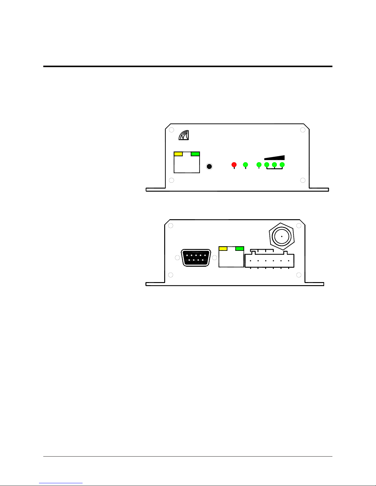
2.0 Connectors
The IP920 connects to the host equipment through a standard DB9 serial port
or RS485/422 interface. All connectors and indicators are illustrated in
Figure 1
Microhard Systems Inc.
COM2
CFG TX RSSI
RX SYS
a. Front Panel
COM1
ETHERNET
RS485/422
TxA
TxB
654321
RxA
RxB
GNG
Vin +
b. Back Panel
Figure 1 Connectors and Indicators
The interface connectors and indicator lights are described below:
4 IP920 Operating Manual: Chapter 2 Electrical/Physical
Page 15

COM1 –– RS-232 Port (DCE). This port is used to interface the IP920 to a
DTE device and operates at 300 to 230,400 bps. The levels are active high RS232 levels, and include (See Appendix A for a complete description):
Table 1 RS-232 Pin Assignment
Pin No. Name Description I/O
1 DCD Data Carrier Detect O
2 RxD Receive Data O
3 TxD Transmit Data I
4 DTR Data Terminal Ready I
5 Gnd Ground
6 DSR Data Set Ready O
7 RTS Request to Send I
8 CTS Clear to Send O
RS-422/485 Port–Alternatively, this port is used to interface the IP920 to a
DTE device with RS-422/485 interface.
Table 2 RS-422 Pin Assignment
Pin No. Name Description I/O
1 TxB (D+) Non-inverting Driver Output O
2 TxA (D-) Inverting Driver Output O
3 RxB (R+) Non-inverting Driver Input I
4 RxA (R-) Inverting Driver Input I
Table 3 RS-485 Pin Assignment
Pin No. Name Description I/O
1 D+ Non-inverting Driver Output
2 D- Inverting Driver Output
3 Interconnect to pin 1
4 Interconnect to pin 2
IP920 Operating Manual: Chapter 2 Electrical/Physical 5
Page 16

COM2 – can be used as console port or data port. Table 4
Table 4 Diagnostic Port Pin Assignment
Pin No. Name Description I/O
1 NC Do Not Connect NC
2 RxD Diagnostic Receive Data I
3 TxD Diagnostic Transmit Data O
4 NC Do Not Connect NC
5 Gnd Ground
6 NC Do Not Connect NC
7 NC Do Not Connect NC
8 NC Do Not Connect NC
ETHERNET –
5 cable should be used when connecting to a Ethernet hub, on the other
hand, a crossover CAT-5 cable should be used when IP920 is connected
to a DTE device, a computer for example.
Ethernet port is a standard RJ-45 port. A straight through CAT-
Antenna Connector - The IP920 uses a reverse polarity TNC connector.
Microhard Systems can provide external cabling and antennas for
applications in which the standard Rubber Duck antenna is not
suitable.
Power Supply–Power should be supplied via pin 5 and 6 of plug-in connector
Table 5 Power Supply
Pin No. Name Description
5 Vin - Power ground and Signal ground (GND)
6 Vin + 8 to 30V DC power supply
6 IP920 Operating Manual: Chapter 2 Electrical/Physical
Page 17

With rubber ducky antennas,
it is normal that alarm LED
illuminates
Concerns should only be
raised in real installations.
sometimes.
2.1 Indicators
Alarm LED – (Amber) located on COM2 connector. It is illuminated when the
load impedance doesn’t match the transmitter impedance. Generally speaking,
there may be problem in the antenna system
MHX Status LED – (Green) located on COM2 connector. It is illuminated
when the MHX core module is present and powered.
RX/Sync LED–Indicates the modem is synchronized and/or is receiving
valid packets of data. See Section 2.2 for complete LED details.
TX LED – Indicates the modem is transmitting data over the air. See
Section 2.2 for complete LED details.
SYS LED –Indicates status of the system. See Section 2.2 for complete
LED details.
Receive Signal Strength Indicator (RSSI) – As the signal strength
increases, the number of active RSSI LED’s increases, starting with the
furthest left. See Section 2.2 for complete LED details.
CFG Button – Holding this button while powering on will boot the unit into
flash file system recovery mode. Default IP address recovery is assigned
to a static IP address:
192.168.1.39
IP920 Operating Manual: Chapter 2 Electrical/Physical 7
Page 18
2.2 LED OPERATION
Cycling power during system
upgrading will corrupt flash file
system. The system will not boot
properly. System can only be
recovered with recovery
procedure.
LED functionality is dependent on the mode of operation. Table 6 explains
LED operation for the various modes.
Table 6 LED Operation
LED
MODE RX/Sync TXMode RSSI1,2,3
Power Up OFF OFF OFF
Configuration Mode OFF OFF OFF
Master ON while receiving
Repeater
During Sync. Acquisition
Repeater When
Synchronized
Remote During Sync.
Acquisition
Remote When
Synchronized
valid data packets
from remotes and
repeaters in the
network
OFF OFF alternating
ON for first portion
of hop interval
OFF OFF alternating
ON ON when
ON RSSI mode
ON for second
portion of hop
interval
transmitting a
packet
based on all
received packets
See Table 8
300ms ON
RSSI mode
based on packets
received from
See Table 8
RSSI mode
based on packets
received from
the Repeater or
Master with
communicates
See Table 8
Remotes
300ms on
which it
2
Table 7 SYS LED Operation
SYSTEM MODE SYS
Normal Mode ON
Recovery Mode Fast Blink
Loading Slow Blink
Upgrading Slow Blink
DO NOT cycle power when system is upgrading.
1
8 IP920 Operating Manual: Chapter 2 Electrical/Physical
1
Master only updates its RSSI after received packets from remotes/repeaters
2
If Remotes have been silent for 2 seconds, repeater will show its RSSI on
packets received from the Master
Page 19

Signal strength, which is also reported in Register S123, is calculated based
on the last four valid received packets with correct CRC, and represented by
RSSI1, 2 and 3.
For remotes, packets are received on every single hop either from a repeater,
or the master.
When calculating RSSI, the master takes into consideration all packets
received from remotes and repeaters. Repeaters and remotes only transmit
back to the master when they have information to send. Therefore, if no data
is coming back to the master then RSSI will never get updated at the master,
and the LED’s will be off.
Table 8 RSSI mode operation
Link Possibility
No Link Scanning
Poor BLINK OFF OFF
Satisfactory ON OFF OFF
Good ON BLINK OFF
Very Good ON ON OFF
Strong ON ON BLINK
Excellent ON ON ON
RSSI1 RSSI2 RSSI3
2.3 VSWR Alarm
The IP920 provides the user a very special indicator on the diagnostic port,
the VSWR alarm. This yellow LED will be illumined if there is a significant
impedance mismatch between the transmission line and its load, i.e. bad
antenna system or bad connections.
Check the antenna and the cables should the alarm go off.
IP920 Operating Manual: Chapter 2 Electrical/Physical 9
Page 20

10 IP920 Operating Manual: Chapter 2 Electrical/Physical
Page 21

IP920 Operating Manual: Chapter 2 Electrical/Physical 11
Page 22

3. User Interfaces
3.0 Overview
The IP920 modem can be easily configured to meet a wide range of needs
and applications. There are three approaches which can be used to access
and configure an IP920.
1. Serial console. COM2 is assigned to system console by default.
2. Web user interface. One can access the system through an embedded
web server inside the IP920 once the IP address is determined.
3. SNMP network management. Simple Network Management Protocol
(SNMP) is another alternative for a network administrator to access the
IP920 system wide.
3.1 Notation
In textUI and webUI, different notations can tell what to expect or what to
do,
“:”–– An item with colon is an item that can be edited or is just for
display;
“…”–– An item with “…” is an item that has submenu or multiple
choices.
For security purpose, there is no
way to reset password into a
default password, therefore system
will become inaccessible if the
password is lost.
3.2 Serial Console
COM2 is used as a system console by default, it can also be used as a second
data port if desired. When used as a console port, the port is configured as
follows,
Baud Rate: 115,200
Data Bits: 8
Parity: None
Stop Bits: 1
Flow Control: None
Make sure the terminal software has same settings as shown above. The
textUI is designed to adapt to any type of terminal, however a VT100 or
ANSI terminal type is recommended for better operation.
User name and password are needed to login to the system. Only the
administrator can login to the system to access the textUI through the
console. Default user name and password are as follows,
IPx20 Login: admin
Password: admin
Password can be changed via user interface. Note that user name and
password are case sensitive. For security purpose, there is no way to reset
password into a default password, therefore system will become inaccessible
if the password is lost.
12 IP920 Operating Manual: Chapter 3 User Interfaces
Page 23

If no password is supplied within 60 seconds after user name is typed in, the
login session will timeout and prompt with login string again.
Figure 2 is a typical screen shot when HyperTerminal is employed as the
terminal program.
Figure 2 textUI Screen Shot
In textUI, typing the leading letter of a menu item can allow you to start
editting a parameter or switch to a submenu. “ESC” is used to exit from a
submenu and back up one step of the hierarchy. “Q” is used to quit from
textUI. When a parameter is modified in a submenu, “U” is used to apply
change(s) and “V” to give up changes just made.
IP920 Operating Manual: Chapter 3 User Interfaces 13
Page 24

An IP920 discovery program
can be found from website:
www.microhardcorp.com
This program helps to find a
dynamic IP address
associated to a IP920.
For security purpose, DO NOT let
the web browser remember user
name and password.
3.3 Web Based User Interface
To make life easier, webUI will be used in following sections instead of a
web based user interface.
Once an IP address is assigned to an IP920 unit, dynamically or statically,
webUI can be accessed using any web browser, such as IE, Netscape and
Mozilla, etc. from a host machine.
If the IP address is 192.168.1.100, simply typing in the following syntax on
the address bar in a favorite browser can bring up the webUI.
http://192.168.1.100
Before the main page show up, user name and password are needed to login
.
to the system. Default user name and password are the same as textUI.
Figure 3 webUI Authentication
Figure 4 webUI Screen Shot
14 IP920 Operating Manual: Chapter 3 User Interfaces
Page 25

3.4 Network Management
IP920 has a built-in SNMP agent to facilitate Simple Network Management
Protocol V1, V2 and V3.
All objects specific to IP920 are hosted under and the private enterprise
number:
21703
IP920 Operating Manual: Chapter 3 User Interfaces 15
Page 26

4. Configuration
4.0 Overview
A similar menu hierarchy applies to all three user interfaces. The following
description is based on mainly webUI. Each function should be the same
among the three approaches unless stated otherwise.
4.1 Main Menu
The following main menu is the root menu which navigates to the
submenus or to the system parameters.
⌦ System Configuration
⌦ Network Configuration
⌦ Radio Configuration
⌦ COM1 Configuration
⌦ COM2 Configuration
⌦ Security Configuration
⌦ System Information
⌦ System Tools
4.2 System Configuration
System configuration gives the ability to setup system time statically or
allow IP920 to synchronize time with a NTP server. There is no backup
battery to support system clock. The system clock starts from default time
upon system reboot, including power on reboot or software reboot. Reconfiguration is needed upon reboot if correct system clock is desired.
16 IP920 Operating Manual: Chapter 4 Configuration
Figure 5 System Configuration
Radio Description: A simple text description can be placed here to
describe a unit. Up to 30 characters are allowed for this description. The
description will be part of the result of discovery program.
Page 27

UTC Time Offset defines whether the offset system is ahead or behind UTC
time. A “+” indicates local time is ahead of UTC time and a “-” indicates
local time is behind UTC time.
Before clicking on Synchronizes with SNTP Server, SNTP server should
have already been set to proper internet time server or network timer server.
See 4.3.2 for details.
IP920 Operating Manual: Chapter 4 Configuration 17
Page 28

4.3 Network Configuration
Network configuration allows the administrator to configure all network
related settings, including local network settings, network time (NTP)
server settings, DHCP server settings and SNMP agent settings.
Figure 6 Network Configuration
Both Ethernet MAC address and Wireless MAC address are also shown in
the page. This information can sometimes be useful for the administrator to
setup the network or for troubleshooting.
4.3.1 Local IP Config …
This is the place where the local network character is determined. The local
network configuration address is a basic for this IP920 node to
communicate with any other network devices through a LAN Ethernet port
as well as remotely through a radio link.
18 IP920 Operating Manual: Chapter 4 Configuration
Figure 7 Local IP Config
Page 29

IP Address Mode: defines whether an IP920 will get an IP address
statically or dynamically. When “static” is selected, the following three
addresses have to be specified manually. Otherwise, when “dhcp” is
selected, the following 3 items can not be edited and will be updated by the
system with correct value after a valid IP address is acquired from a DHCP
server inside the network.
Make sure a DHCP server is accessible prior to changing IP Address Mode
to dhcp.
IP Address: Editable when IP Address Mode is set to “static”. Only a valid
static IP address is acceptable.
IP Subnet Mask: Editable when IP Address Mode is set to “static”. Only a
valid static subnet mask address is acceptable.
IP Gateway: Editable when IP Address Mode is set to “static”. Only a
valid static gateway address is acceptable.
4.3.2 NTP Server Config ...
This is where to setup the NTP server for the local IP920 to synchronize its
clock with.
NTP Server Status: NTP service can be enabled or disabled. When
enabled, this local IP920 will attempt to synchronize its clock with a
specific NTP server. To save system resources, it should be disabled if NTP
server is not accessible or this service is not desired.
NTP Server (IP/Name): Both IP address or domain name can be used to
specify a NTP server. If NTP service is desired, the network has to be
Figure 8 NTP Server Config
designed so that this local IP920 has internet access or it can access the
NTP server that resides inside a LAN.
IP920 Operating Manual: Chapter 4 Configuration 19
Page 30

This service could conflict with an
existing DHCP server in a wired
LAN network. Caution must be
taken when this service is desired
and enabled.
4.3.3 DHCP Server Config ...
IP920 can be configured to provide DHCP server service for a whole LAN
network section, including wired and wireless. Normally, one can enable a
DHCP server on a master IP920 so that it can assign dynamic IP addresses
to all the remotes wirelessly. It can also assign a dynamic IP address to a
host machine which is connected through a LAN port. This machine can be
used as a maintenance station for the whole radio network.
The DHCP server also manages up to 5 MAC address bindings. With MAC
address binging, the DHCP server reserves certain IP addresses for
specified MAC addresses which connect to the network remotely or locally.
Figure 9 DHCP Server Config
Server Status: DHCP service can be enabled or disabled. It is disabled by
default. When enabled, it can assign an IP address for both the LAN port
and the radio network.
Server Subnet: IP netmask to be assigned along with the IP address in
response to a DHCP request. [0.0.0.0]
Starting Address: Lower boundary of IP address pool to be provided by
this server. [0.0.0.0]
Ending Address: Upper boundary of IP address pool to be provided by this
server. [0.0.0.0]
DNS Address: Domain Name Server address to be provided by this server.
20 IP920 Operating Manual: Chapter 4 Configuration
Page 31

WINS Address: Windows Internet Naming Service server address to be
provided by this server.
New Binding MAC: a valid MAC address which gets the same IP address
when requesting from this DHCP server.
New Binding IP: a valid IP address will be assigned to the specific MAC
address.
Add: This action will add a new binding into the list temporarily.
Delete: a selected MAC binding can be deleted from the list.
All the parameters take effective only when the page is submitted.
4.3.4 Bridge Config ...
Spanning Tree Protocol (STP) can be enabled or disabled here to prevent
undesirable loops in the network
Figure 10 NTP Server Config
If multiple IP920 will be directly connected to a network, STP should be
enabled. STP should be disabled if only the master IP920 is connected to a
network and the other units are connected to the network indirectly.
Disabling STP can reduce network traffic to some extent.
IP920 Operating Manual: Chapter 4 Configuration 21
Page 32

4.3.5 SNMP Agent Config ...
Figure 11 SNMP Agent Config
SNMP Operation Mode: SNMP agent can be disabled or enabled. If
disabled, no SNMP service is provided from the device. When enabled, this
SNMP agent can handle SNMPv1, SNMPv2c and SNMPv3.
Read Only Community Name: This gives the agent ability to handle
request from SNMPv1 and SNMPv2c clients. This community name has
only read priority
Read Write Community Name: This gives the agent ability to handle
request from SNMPv1 and SNMPv2c clients. This community name has
read/write priority.
SNMP V3 User Name: Defines user name for SNMPv3
V3 User Read Write Limit: Defines accessibility of SNMPv3, can choose
from read-only or read-write priority. If "read-only" is selected, the
SNMPv3 user only can read information; if "read-write" is selected, the
SNMPv3 user can read and write (set) variables.
V3 User Authentication Level: Defines SNMPv3 user's authentication
level. Choose from,
noAuthNoPriv: don’t need authentication and encryption.
AuthNoPriv: need authentication but don’t need encryption.
AuthPriv: need authentication but don’t need encryption.
22 IP920 Operating Manual: Chapter 4 Configuration
Page 33

V3 Authentication Password: SNMPv3 user's authentication password.
This is only valid when V3 User Authentication Level is set to AuthNoPriv
or AuthPriv.
V3 Privacy Password: SNMPv3 user's encryption password. This is only
valid when V3 User Authentication Level is set to AuthPriv.
SNMP Trap Version: Select which version of trap will be sent in case
failure or alarm.
Auth Failure Traps: If select "Enable", an authentication failure trap will
be generated upon authentication failure.
Trap Community Name: The community name can receive traps.
Trap Manage Host IP: Defines a host IP address where traps will be sent
to.
IP920 Operating Manual: Chapter 4 Configuration 23
Page 34

4.4 Radio Configuration
All radio related parameter modifications take place under this submenu.
Operating mode, output power, wireless link rate, radio network topology,
roaming and other radio network parameters can be modified here.
Figure 12 Radio Configuration
Operating Mode: A radio can be configured into one of the three modes,
Master, Repeater and Remote.
Master –– In any given network, there is always only one
Master. All other units should be configured as either Remotes or
Repeaters. When defined as a Master, the modem broadcasts data to all
Remotes and Repeaters or talks to a specific remote, based on the network
type. The master radio controls synchronization of the whole radio network.
Remote –– Up to 65533 Remotes may exist in a network, all of
which communicate with the common Master (either directly or via
Repeater(s)). Remotes cannot directly communicate with one other. The
Master initiates communications by sending a broadcast message to all
Remotes. After synchronized with the Master unit, Remote(s) can transmit
data on a certain channel for a certain time period determined by the Master
unit.
Repeater –– A more precise title would be Repeater/Remote,
because a Repeater also has much of the same functionality as a Remote. A
terminal can be connected at the Repeater location and communicate with
the Master terminal. The presence of one Repeater in a network
automatically degrades system throughput by half. Additional Repeaters,
regardless of the quantity, do not diminish system throughput any further.
The Repeater(s) store any data from the Master or upper stream repeater and
forward to the down stream Repeater or remote, vice versa
24 IP920 Operating Manual: Chapter 4 Configuration
Page 35

Network Name: This is a unique ID for a radio network. All units inside
the same network should have the same network name. Network name is
also a factor used by the system to generate the hopping pattern. This
network name is also a seed to generate an encryption key to encrypt the
data over air.
Link Rate: is the speed and optimization method for which modules
will communicate over the RF link.
The possible value is:
*345kbps
Unit Address: editable on remote and repeater. The Unit Address
identifies an individual unit in the radio network.
Unit Address 1 is reserved for the Master unit.
The Unit Address uniquely identifies each Remote and Repeater from one
another. Each unit in a multipoint system must have a unique Unit Address
ranging from 2 to 65534. Do not use a Unit Address more than once within
the same Network. This is required because the Master must be able to
acknowledge each unit individually, based on the Unit Address.
RF Output Power: The Output Power Level determines at what power
the IP920 transmits. The IP920’s sensitive receiver can operate with very
low power levels, so it is recommended that the lowest power necessary is
used; using excessive power contributes to unnecessary “RF pollution”.
The allowable settings are from 100 mW to 1000 mW.
Ideally, you should test the communications performance between units
starting from a low power level and working upward until the RSSI is
sufficiently high and a reliable link is established. The conditions will vary
widely between applications, the output power settings can be calculated
based on following information.
• Transmitter antenna gain
• Cable loss
• Effective radiated power (ERP) requirement by FCC Regulations
Power Setting = 36 – Antenna Gain – Cable Loss
The power setting must be no more than the above calculation value.
higher is a violation of FCC rules. See IMPORTANT warning to follow.
Any
IP920 Operating Manual: Chapter 4 Configuration 25
Page 36

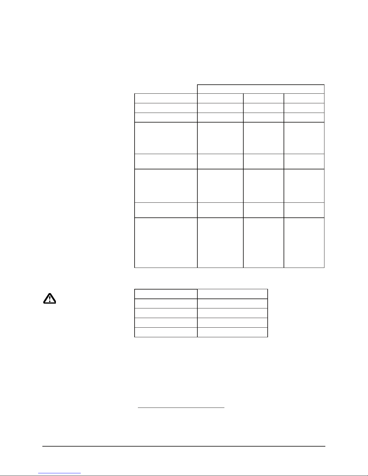
Table 9 Output Power
Power Setting
(dBm)
Approx. Output Power
(mW)
20 100
21 125
22 160
23
24
25
26
27
28
29
30
200
250
320
400
500
630
800
1000
IMPORTANT:
FCC Regulations allow up to 36 dBi effective radiated power (ERP).
Therefore, the sum of the transmitted power (in dBm), the cabling loss
and the antenna gain cannot exceed 36 dBi.
1 mW = 0 dBm
10 mW = 10 dBm
100 mW = 20 dBm
1000 mW = 30 dBm
For example, when transmitting 1 Watt (30 dBm), the antenna gain
cannot exceed 36 - 30 = 6 dBi. If an antenna with a gain higher than 6
dBi were to be used, the power setting must be adjusted appropriately.
Microhard Systems Inc. limits the MHX 920’s transmitted power to
100mW for all units purchased with antennas with gain above 6dBi.
Retransmissions: In point-to-multipoint mode, the Master will
retransmit each data packet exactly the number of times defined by the
Packet Retransmissions parameter. The remote will retransmit its packet
until the retransmission limit is reached or an acknowledgement is received.
If the limit is reached, the module will give up and discard the data.
In point-to-point mode, the Unit will only retransmit the packet if it does
not get an acknowledgement from its counterpart. In this case, the unit will
continue to retransmit until an acknowledgement is received, or the
retransmission limit is reached. When the retransmission limit is reached,
the unit discards the packet.
Recipients of the packet will discard any duplicates. The valid settings for
this parameter are 0 to 255 retransmissions.
26 IP920 Operating Manual: Chapter 4 Configuration
Page 37

Network Type: defines radio network topology.
*Point-to-Multipoint (PMP) network
Point-to-Point (PP) network
Peer to Peer (P2P) network
Everyone to Everyone (E2E) network
In a point to multipoint (PMP) network, the master unit broadcasts packets
to every remotes/repeaters in the network. Destination address is set to
65535 automatically on the master for PMP network.
In a point to point (PP) network, the master only communicates with one
remote whose unit address matches the destination address of this master
unit. The destination address needs to be set properly on the master unit of a
point-to-point network.
A peer to peer (P2P) would allow remotes in the network to communicate
with each other. The destination address should be set to the unit address of
its peer
An Everyone to Everyone (E2E) would allow all remotes in the network to
communicate with each other. The destination address is set to 65535 on all
units inside an E2E network.
Roaming Address: Only valid on remote/repeater units. This
parameter defines which upstream unit this unit should synchronize with. If
a particular unit address is set, this unit will only try to synchronize with
that specific unit.
Unit address 1 stands for the Master in the network;
Other unit address (2~65534) specifies an upstream repeater;
Broadcast address 65535 tells this unit to find an available upstream unit
(master or repeater) and synchronize with it. This unit will look for another
unit in case of synchronization loss.
Repeater: can only be seen on a master unit. It tells the master if
repeater(s) exists in a radio network.
Optimization: can only be seen on a master unit. It tells the master to
optimize system in three different ways, High Throughput/Balanced/Low
Latency.
High Throughput
*Balanced
Low Latency
When throughput is the priority in an application, High throughput
should be chosen; when a system has short packets and latency
requirement is the priority, Low Latency should be selected;
otherwise, the selection of Balanced is a compromise of throughput
and latency.
IP920 Operating Manual: Chapter 4 Configuration 27
Page 38

4.5 COM1 and COM2 Configuration
Serial device server can be configured under these two submenus.
Normally, serial device server is used to bring serial device data into a LAN
network through TCP, UDP or multicast. When configured properly, data
from a serial port on one IP920 could output to the serial port on another
IP920.
Settings for two serial ports are mostly the same except minor differences.
COM1 is a dedicated data port and can only be configured for data
communication purpose. COM2 is setup as a system console by default and
can be used as a second data communication port. There is no hardware
flow control available on COM2.
This section will mainly describe how to setup COM1.
28 IP920 Operating Manual: Chapter 4 Configuration
Page 39

Figure 13 Serial Port Configuration
4.5.1 Serial Port Settings
Port Status: serial port server can be enabled or disabled. The COM2 is
normally disabled and used for system console. When data communication
is desired on COM2, this setting should be set to “enabled”. Escape
sequence “+++” can be used to escape from data mode and to go back into
console mode. Please note, “+++” needs to be issued at the right baud rate
to make the port switch modes.
Channel Mode: determines what serial interface shall be used to connect to
external serial devices, RS232, RS422 (4-wire) or RS485 (2-wire). Only
COM1 can be configured to use different serial channel node. DB9 port will
be disabled when RS422 or RS485 mode is selected.
Baud Rate: baud rate used by the server to receive from or transmit to
serial port. Baud rate can be set from 300bps to 230,400 bps.
Data Format: defines serial port framing format, including data bits, parity,
and stop bits. For example, 8N1 means 8 data bits, No parity, and 1 stop bit.
IP920 Operating Manual: Chapter 4 Configuration 29
Page 40

Flow Control: To make serial port data communication reliably, hardware
handshaking can be used. If a serial device doesn’t support hardware
handshaking, flow control should be set to “None”. When CTS Framing is
selected, IP920 uses CTS signal to gate output data on serial port. The
following figure shows timing diagram of CTS output data framing.
CTS
RXD
Pre-Data
Delay (ms)
Data leaving IP920
Post-Data
Delay (ms)
Figure 14 CTS Output Data Framing
Pre-Data Delay (ms): See Figure 14.
Post-Data Delay (ms): See Figure 14.
Data Mode: defines serial data output framing. Serial port service adds
time gap between data frames to comply with MODBUS protocol when
data mode is set to MODBUS. At least a 3.5 character time gap is inserted.
This value can be modified by the Character Timeout setting. On the other
hand, the serial server will output serial data to the serial port as quick as
possible in transparent mode; no delays will be inserted between frames.
30 IP920 Operating Manual: Chapter 4 Configuration
Page 41

Character Timeout: in MODBUS mode, it tells the serial server when to
wrap up incoming data from the serial port and to start to transmit. Frames
will be marked as bad frames if the time gap between frames is greater than
1.5 chars, but less than the character timeout.
Serial server also uses this parameter to determine the time gap inserted
between frames. It is measured in characters and related to baud rate. For
example, if baud rate is set to 9600, it takes about 1ms to transmit one
character. When character timeout is set to 4, timeout value is set to 4ms.
When calculated time is less than 3.5 chars, the server will set character
timeout to 3.5 chars.
When the baud rate is greater than 19200bps, the minimal character timeout
is set to 750us internally.
Maximum Packet Size: defines the buffer size the serial server uses to
receive data from the serial port. When the server detects character timeout
or the buffer is full, it packetizes the received frame and transmits.
4.5.2 Serial Port Protocols
The serial server can be set to use one of the following protocols to transmit
serial port to a remote unit.
⌦ TCP Client
⌦ TCP Server
⌦ TCP Client/Server
⌦ UDP Point to Point
⌦ UDP Point to Multipoint (P)
⌦ UDP Point to Multipoint (MP)
TCP Client
When TCP Client protocol is selected, IP920 takes initiative to find and
connect to a remote TCP server when data is received from its serial port.
The TCP connection is terminated by this unit when the data session is done
and connection timeout has expired. If no TCP connection can be
established, serial port data is dropped.
Remote Server Address: IP address of a TCP server which is ready to
accept serial port data through a TCP connection. It might be sitting on a
LAN network server.
Remote Server Port: a TCP port the remote server listens to. It allows a
TCP connection to be created by a TCP client to carry serial port data.
Outgoing Connection Timeout (s): tells IP920 when to terminate the TCP
connection if the connection is in idle state.
IP920 Operating Manual: Chapter 4 Configuration 31
Page 42

TCP Server
When TCP Server protocol is selected, IP920 is put into a passive mode. It
listens on a specific TCP port to accept an incoming TCP connection from a
remote station, for example a work station inside a LAN network. Once a
connection is established any received data from serial port is passed on to
the remote TCP client; otherwise serial data is simply dropped.
Local Listening Port: a TCP port the remote server listens to. It allows a
TCP connection to be created by a TCP client to carry serial port data.
Incoming Connection Timeout (s): tells the TCP server when to terminate
the TCP connection if the connection is in idle state.
32 IP920 Operating Manual: Chapter 4 Configuration
Page 43

UDP Point to Point
MP
P
UDP Point to Multipoint
MP
MP
TCP Client/Server
When TCP Client/Server protocol is selected, IP920 is set in a combined
mode. It can take initiative to create a TCP connection when data is
received from a serial port and no TCP connection already exists; it can also
passively wait for a remote TCP client to create a TCP connection and pass
serial data back and forth. See TCP Client and TCP server for details.
UDP Point to Point
When UDP Point to Point protocol is selected, IP920 transmits serial data to
a specific point with UDP packets. It also accepts UDP serial data from that
particular node.
Remote IP Address: a remote IP address to which UDP packets are sent by
the IP920 when data is received from a serial port.
Remote Port: a remote UDP port to which UDP packets are sent by the
IP920 when data is received from serial port.
Listening Port: a UDP port the IP920 unit listens to. UDP packets received
on this port are transmitted to the local serial port.
UDP Point to Multipoint (P)
This protocol is set on the unit who sends multicast UDP packets.
Normally, this unit is the master radio of a network.
Multicast IP Address: a valid multicast address this unit uses to send
multicast UDP packets upon receiving data from serial port. 224.1.1.1
Multicast address is a good example.
Multicast Port: a UDP port this base station sends UDP packets to.
Multipoint stations should listen to this port in order to receive multicast
packets.
Listening Port: a UDP port the base station uses to accept data from
multiple remote units.
Time to Live: TTL for multicast packets.
IP920 Operating Manual: Chapter 4 Configuration 33
UDP Point to Multipoint (MP)
This protocol is selected on the units who receive multicast UDP packets.
Normally, this protocol is set on remote units.
Remote IP Address: a remote IP address to which UDP packets are sent by
this IP920 when data is received from serial port. Normally this is set to the
IP address of the Master unit.
Remote Port: a remote UDP port to which UDP packets are sent by this
IP920 when data is received from serial port. Normally this port number
matches Listening Port of a UDP Point to Multipoint (P), typically the
master.
Page 44

Multicast IP Address: a valid multicast address that this unit uses to listen
to multicast UDP packets sent by a UDP Point to Multipoint (P). 224.1.1.1
Multicast address is a good example.
Multicast Port: a UDP port that this unit used to listen to multicast UDP
packets sent by UDP Point to Multipoint (P).
UDP Multipoint to Multipoint
Multicast IP Address: a valid multicast address this unit uses to send
multicast UDP packets upon receiving data from serial port. 224.1.1.1
Multicast address is a good example.
Multicast Port: a UDP port this base station sends UDP packets to.
Multipoint stations should listen to this port in order to receive multicast
packets.
Listening Multicast IP Address: a valid multicast address that this unit
uses to listen to multicast UDP packets sent by a UDP Multipoint to
Multipoint. 224.1.1.1 Multicast address is a good example.
Listening Multicast Port: A UDP port that this unit used to listen to
multicast UDP packets sent by UDP Multipoint to Multipoint.
Time to Live: TTL for multicast packets.
34 IP920 Operating Manual: Chapter 4 Configuration
Page 45

4.6 Security Configuration
This section describes security measures built into IP920. These security
measures cover from wireless data traffic security to device management
security.
4.6.1 Administrator Password
To keep a system secure, the administrator password should be modified to
a different password instead of using the factory default password. This
menu gives the ability to change the password for the administrator.
Figure 15 Change Password for Admin
IP920 Operating Manual: Chapter 4 Configuration 35
Page 46

4.6.2 Upgrade Password
Upgrade password protects IP920 units from being upgraded (package
upgrade) by unauthorized personel. Default password should be avoided
when system is deployed to make the units more secure.
Figure 16 Change Password for Upgrade
4.6.3 Wireless WEP Encryption
Network traffic over air can be encrypted by Wired Equivalent Privacy
(WEP) encryption algorithm.
WEP encryption is disabled by default to keep overhead minimum, it
should be enabled if over air encryption is required. When enabled, more
protocol overhead is added on the packets being transmitted; therefore a
minor throughput decrease shall be expected.
36 IP920 Operating Manual: Chapter 4 Configuration
Page 47

Figure 17 WEP Encryption
WEP Status: Indicates WEP encryption is enabled or disabled.
WEP Key Type: 64 bit encryption key or 128 bit encryption can be used to
secure wireless data traffic. Compare to 64 bit encryption, 128 bit
encryption is stronger, but adds more overhead on wireless traffic.
Key Generation: WEP key1 to key4 can be generated to the system upon
Key Phrase when Key Generation is checked. Otherwise WEP key1 to key4
can be chosen by user.
Key Phrase: A seed to automatically generate a selected WEP Key if Key
Generation is checked.
Key1~Key4: Up to 4 different WEP Key can be setup on each unit.
Generate Key: An action to generate a WEP key temporarily on the UI.
All the parameters take effective only when the page is submitted.
IP920 Operating Manual: Chapter 4 Configuration 37
Page 48

4.7 System Information
System Information is used for displaying diagnostic and statistic
information. This information includes:
⌦ Ethernet Packet Statistics …
⌦ Radio Information ...
⌦ COM1 Connection Status ...
⌦ COM2 Connection Status ...
⌦ Other information
All this information can help an administrator to setup a network or with
troubleshooting.
Figure 18 System Information
38 IP920 Operating Manual: Chapter 4 Configuration
Page 49

4.8 System Tools
System tools are used for changing the administrator password, upgrading
the system, and restoring default radio settings.
Figure 19 System Tools
4.8.1 Firmware Upgrade
Package Upgrade from webUI
When a newer system version is available, the upgrade package can be
uploaded to IP920 through FTP.
System upgrade user is different from system administrator. User name for
system upgrade is “upgrade”. Password is “admin” by default. In case of a
command line FTP client is used, both username and password should be
punched in.
If an upgrade procedure is started from this page, only the password may be
needed. This page will be routed to a FTP page so that upgrade package can
be dragged and dropped into IP920 to upgrade the unit.
FTP session also works remotely, meaning that a remote unit can be
upgraded remotely.
IP920 Operating Manual: Chapter 4 Configuration 39
Page 50

Package Upgrade from Command Line FTP
This section describes the procedure to upgrade an IP920 unit with package
upgrade file (*.pkg).
Download upgrade package and put it into a known directory;
Start up a command line window from the system;
Change current directory to where the package file is located;
Start a FTP session as shown below;
Figure 20 Command Line Package Upgrade
Provide proper user name and password to login;
Change transfer protocol to BINARY mode;
Push package upgrade file into the system with “put” command;
Package upgrade takes up to 2 minutes to complete. Wait until
“SYS” LED stop flashing.
If “SYS” LED doesn’t come back to solid ON, the unit need to be
manually restarted.
40 IP920 Operating Manual: Chapter 4 Configuration
Page 51

Recovery from Command Line FTP
In case the unit needs to be upgraded from recovery mode, the following
procedure should be taken. Recovery images have file extension *.img.
Download recovery image and save it into a known directory;
Start up a command line window from the system;
Change current directory to where the package file is located;
Cycle power on the IP920 unit with CFG button pressed and held
down until “SYS” LED is observed in fast flash mode;
Start a FTP session as shown below; the IP address is set to a
default 192.168.1.39;
Figure 21 Command Line Recovery
Provide proper user name and password to login;
Change transfer protocol to BINARY mode;
Push package upgrade file into the system with “put” command;
Package upgrade takes more than 2 minutes to complete. The
“SYS” LED changes from fast flash to slow flash to indicate
upgrading is in process;
The unit automatically reboots after the recovery procedure is
completed.
IP920 Operating Manual: Chapter 4 Configuration 41
Page 52

Parameter Change through Command Line FTP
This section describes the procedure to download system configuration file
through FTP and upload system configuration parameter file.
The system settings can be changed through FTP session rather than
navigating through textUI or webUI.
Start up a command line window from the system;
Change current directory to where the system configuration file
needs to be;
Start a FTP session as shown below;
Figure 22 Command Line Parameter Loading
Provide proper user name (upgrade) and password (admin by
default) to login;
Download “system.conf”;
Make necessary changes in “system.conf”. Comments can be
found inside the file.
Push “system.conf” file into the system with “put” command;
The system applies new parameters and reboots itself.
42 IP920 Operating Manual: Chapter 4 Configuration
Page 53

4.8.2 Reset Radio to Defaults
To troubleshoot radio link problems, factory defaults can be used from this
menu. This menu allows one to reset the radio using different groups of
defaults to verify wireless link; should the link be in question.
4.8.3 Reboot System
This command is used to reboot system without physically power cycle the
IP920 unit locally or remotely.
4.8.4 Reset System to Default
This command is used to reset all settings to factory defaults.
IP920 Operating Manual: Chapter 4 Configuration 43
Page 54

44 IP920 Operating Manual: Chapter 4 Configuration
Page 55

5. Installation
5.0 Overview
The installation, removal
or maintenance of all
antenna components must
be carried out by
qualified and experienced
personnel.
The installation, removal or maintenance of all antenna
components must be carried out by qualified and
experienced personnel.
The IP920 complies with FCC part 15 at the modular level for operation in
the license-free 902-928 MHz ISM band. This chapter provides guidelines
for installing and deploying equipment which incorporates the IP920
module.
5.1 Estimating the Gain Margin
Successful communication between IP920 modules is dependent on three
main factors:
• System Gain
• Path Loss
• Interference
System gain is a calculation in dB describing the performance to be
expected between a transmitter-receiver pair. The number can be calculated
based on knowledge of the equipment being deployed. The following four
factors make up a system gain calculation:
1. Transmitter power (user selectable 0, 20 to 30dBm)
2. Transmitter gain (transmitting antenna gain minus cabling loss between
the transmitting antenna and the IP920 module)
3. Receiver gain (Receiving antenna gain minus cabling loss between the
receiving antenna and the module)
4. Receiver sensitivity (Specified as -106dBm on the IP920 module)
In the following illustration, the transmitting antenna has a gain of 6 dB,
and the receiving antenna has a gain of 3 dB. The cable loss between the
module and the antenna is 2 dB on both the transmitting and receiving side.
Cable Loss = 2 dBCable Loss = 2 dB
Transmitter
30 dBm
Output Power
Antenna Gain = 6 dB
Antenna Gain = 3 dB
Receiver
Sensitivity =
-106 dBm
Figure 23 Gain Calculation
The power level has been set to 30dBm (1W) on the transmitter, and the
receiver sensitivity for the IP920 is -106dBm.
System gain would be calculated to be:
30 - 2 + 6 + 3 - 2 + 106 = 143 dB.
IP920 Operating Manual: Chapter 5 Installation 45
Page 56

When deploying your system, care must be taken to ensure the path loss
(reduction of signal strength from transmitter to receiver in dB) between
equipment does not exceed the system gain (143 dB in the above example).
It is recommended to design for a gain margin of at least 20 dB to ensure
reliable communication. Gain margin is the difference between system gain
and path loss. Referring to the same example, suppose the path loss is 113
dB, the gain margin would be 30 dB, which is more than adequate for
Mobile
Height
Base Height (m)
(m)
reliable communication.
Path loss is a very complicated calculation which mainly depends on the
terrain profile, and the height of the antennas off the ground.
Distance (km)
Figure 24 System Deployment
and antenna separation: These numbers are real averages taken from rural
environments. They do not apply to urban, non-line-of-sight environments.
Table 10 Path Loss
The following table provides path loss numbers for varying antenna heights
Distance
(km)
Base Height
(m)
Mobile Height
(m)
Path Loss
(dB)
5 15 2.5 116.5
5 30 2.5 110.9
8 15 2.5 124.1
8 15 5 117.7
8 15 10 105
16 15 2.5 135.3
16 15 5 128.9
16 15 10 116.2
16 30 10 109.6
16 30 5 122.4
16 30 2.5 128.8
46 IP920 Operating Manual: Chapter 5 Installation
Once the equipment is deployed, you can verify the signal strength by
entering into Command Mode and reading Register S123. This register
provides the average signal strength in dBm. The minimum strength for
communication is roughly -106dBm. For consistent reliable
communication, you should try to deploy the equipment such that signal
strength exceeds -88dBm.
Page 57

WARNING
To satisfy FCC RF exposure
requirements for mobile
transmitting devices, a
separation distance of 23 cm
or more should be
maintained between the
antenna of this device and
persons during device
operation. To ensure
compliance, operations at
closer than this distance is
not recommended. The
antenna used for this
transmitter must not be colocated in conjunction with
any other antenna or
transmitter
WARNING
Direct human contact with
the antenna is potentially
unhealthy when a IP920 is
generating RF energy.
Always ensure that the IP920
equipment is powered down
during installation.
5.2 Installing External Cables, Antennas and
Lightning Arrestors
The installation, removal or maintenance of all antenna components must be
carried out by qualified and experienced personnel.
Never work on an antenna system when there is lightning in the area.
Direct human contact with the antenna is potentially unhealthy when the
IP920 is generating RF energy. Always ensure that the IP920 equipment is
powered down during installation. At all times, a distance of 23 cm must be
maintained between the antenna and any person when the device is in
operation.
Surge Arrestors
The most effective protection against lightning is to install two lightning
(surge) arrestors, one at the antenna, the other at the interface with the
equipment. The surge arrestor grounding system should be fully
interconnected with the transmission tower and power grounding systems to
form a single, fully integrated ground circuit. Typically, both ports on surge
arrestors are N-female.
External Filter
Although the IP920 is capable of filtering out RF noise in most
environments, there are circumstances that require external filtering.
Paging towers, and cellular base stations in close proximity to the IP920
antenna can desensitize the receiver. Microhard Systems’ external cavity
filter eliminates this problem. The filter has two N-female ports and should
be connected in line at the interface to the RF equipment.
Weatherproofing
Type N and RTNC connectors are not weatherproof. All connectors should
be taped with rubber splicing tape (weatherproofing tape), and then coated
with a sealant.
Cabling
WARNING
Never work on an antenna
system when there is
lightning in the area.
IP920 Operating Manual: Chapter 5 Installation 47
The following coax cables are recommended:
Table 11 Cable Loss
Cable Loss (dB/100ft)
LMR 195 10.7
LMR 400 3.9
LMR 600 2.5
Page 58

Factors to take into consideration when choosing a cable are:
• price;
• bend radius limitations (the lower performance cables generally can
bend more sharply)
• performance requirements; and,
• distance between the equipment and the antenna.
When installing the cable, always begin fastening at the top near the
antenna connector/surge arrestor. The cable must be supported at the top
with a hose clamp or wrap lock, and at 5 ft intervals down the length of the
tower. Over-tightening the fasteners will dent the cable and reduce
performance. If properly grounded surge arrestors are not installed at both
the top and the bottom of the cable, then the cable should be grounded to
the tower at these locations using a cable grounding kit. If the tower is nonconductive, then a separate conductor, physically separate from the cable,
should be run down the tower.
48 IP920 Operating Manual: Chapter 5 Installation
Page 59

Antenna
To comply with FCC regulations,
.you must limit ERP to 36 dBm or
less.
Before choosing an antenna, you should have some knowledge of the path
loss and the topology of the equipment. If the equipment is in a fixed
location and is to communicate with only one other unit also in a fixed
location, then a Yagi antenna is suitable. Choose a Yagi with enough gain
to ensure adequate gain margin. When deploying the Yagi, point the
antenna towards the intended target, ensuring the antenna elements are
perpendicular to the ground for vertical polarization.
In applications where there are multiple units that you must communicate
with or unit, which are in motion, you may select an Omni-directional
antenna with appropriate gain.
See appendix A for a list of approved antennas that can be used with
the IP920 radio modem. If you require another type of antenna please
contact Microhard Systems Inc. The IP920 CANNOT be used with any
antenna that does not appear in Appendix A.
Microhard Systems Inc. can provide you with approved antennas to ensure
FCC and Industry Canada compliance.
FCC Regulations allow up to 36dBm effective radiated power (ERP).
Therefore, the sum of the transmitted power (in dBm), the cabling loss
and the antenna gain cannot exceed 36dBm with respect to the isotropic
radiator.
ERP is calculated as follows:
ERP = Tx Power (dBm) - Cable/Connector Loss (dB) + Antenna Gain (dBi)
Antenna Gains must be in dBi when calculating the 36dBm ERP limit.
1dBd = 2.15dBi
Use the guidelines in the previous section for calculating cable and
connector losses. If cabling and connector losses are 2 dB, then the
maximum allowable gain of the antenna will be 8 dB.
IP920 Operating Manual: Chapter 5 Installation 49
Page 60

50 IP920 Operating Manual: Chapter 5 Installation
Page 61

Modem
(DCE)
1
2
3
←
4
←
5
6
7
←
8
Arrows denote the direction
that signals are asserted (e.g.,
DCD originates at the DCE
and tells the DTE that a
carrier is present).
Signal
DCD
RX
TX
DTR
SG
DSR
RTS
CTS
Microprocessor
→
→
→
→
→
Host
(DTE)
IN
IN
OUT
OUT
IN
IN
OUT
IN
A. Serial Interface
The IP920 module uses 8 pins on the header connector for asynchronous
serial I/O. The interface conforms to standard RS-232 signals without level
shifting, so direct connection to a host microprocessor is possible.
The signals in the asynchronous serial interface are described below:
DCD
Data Carrier Detect - Output from Modem - When asserted (TTL low),
DCD informs the DTE that a communications link has been
established with another IP920.
RX
Receive Data - Output from Modem - Signals transferred from the
IP920 are received by the DTE via RX.
TX
Transmit Data - Input to Modem - Signals are transmitted from the
DTE via TX to the IP920.
DTR
Data Terminal Ready - Input to Modem - Asserted (TTL low) by the
DTE to inform the modem that it is alive and ready for
communications.
SG
Signal Ground - Provides a ground reference for all signals transmitted
by both DTE and DCE.
DSR
Data Set Ready - Output from Modem - Asserted (TTL low) by the
DCE to inform the DTE that it is alive and ready for communications.
DSR is the modem’s equivalent of the DTR signal.
RTS
Request to Send - Input to Modem - A “handshaking” signal which is
asserted by the DTE (TTL low) when it is ready. When hardware
handshaking is used, the RTS signal indicates to the DCE that the host
can receive data.
CTS
Clear to Send - Output from Modem - A “handshaking” signal which is
asserted by the DCE (TTL low) when it has enabled communications
and transmission from the DTE can commence. When hardware
handshaking is used, the CTS signal indicates to the host that the DCE
can receive data.
IP920 Operating Manual: A Serial Interface 51
Notes: It is typical to refer to RX and TX from the perspective of the DTE.
This should be kept in mind when looking at signals relative to the
modem (DCE); the modem transmits data on the RX line, and
receives on TX.
“DCE” and “modem” are often synonymous since a modem is typically a
DCE device.
“DTE” is, in most applications, a device such as a host microprocessor.
Page 62

52 IP920 Operating Manual: Appendix A Serial Interface
Page 63

B. RS485 Wiring
IP920 can be connected into 2-wire or 4-wire RS-485 network. Transmission line termination should be placed only
at the extreme ends of the data line if the RS-485 network runs at high data rates with long wiring.
2-wire RS-485
Figure 25 shows a typical two-wire configuration of RS-485 IP920. Two wires are shared by transmission and
receiving in 2-wire configuration, so it is very important for the modem to grab the line at right time when it
transmits. Note again that the transmission line termination is needed if the system has high data rates and long
wiring runs.
A (D-)
B (D+)
4
3
2
1
Figure 25 2-wireRS485 IP920
4-wire RS-485
A IP920 RS-485 can also be connected into a RS-485 network in a four-wire fashion as shown in Figure 26. In a
four-wire network it is necessary that one node be a master node and all others be remotes. The network is
connected so that the master node communicates to all remote nodes. All remote nodes communicate only with the
master node. Since the remote nodes never listen to another remote response to the master, a remote node cannot
reply incorrectly to another remote node.
RxA (R-)
RxB (R+)
TxA (D-)
TxB (D+)
4
3
2
1
Figure 26 4-wire RS485 IP920
IP920 Operating Manual: Appendix B RS485 Wiring 53
Page 64

54 IP920 Operating Manual: Appendix B RS485 Wiring
Page 65

C. Mounting Dimensions
4.2500
3.7500
IP920
TOP VIEW
3.885
4.760
0.1250
4 HOLES
0.375" I/D
FRONT
IP920 Operating Manual: Appendix C Mounting Dimensions 55
Page 66

56 IP920 Operating Manual: Appendix C Mounting Dimensions.
Page 67

D. Technical Specifications
Table 12 Technical Specifications
Data Interface Asynchronous Serial RS232, RS422/RS485, RJ-45 Ethernet
RS232 Signals Sig. Gnd, TX, RX, DCD, DSR, DTR, RTS, CTS
RS422/485 Signals Sig. Gnd, TxB, TxA, RxB, RxA
Serial Data Protocol TCP, UDP
Network Protocol TCP/IP, ICMP,DHCP, ARP, HTTP, FTP, SNMP
Bandwidth / Data Rate
Communications Range1 +96 kilometers (60 miles)
Power Requirements 8 VDC to 30 VDC
Power Consumption 600 mA max, 300 mA typical; 95 mA receive @ 12VDC
Operating Frequency 902-928 MHz
System Gain 136 dB
Sensitivity -106 dBm
Output Power 100 to1000mW (1dB steps user-selectable)
Spreading Code Frequency Hopping
Hopping Patterns Based on network address, 232
Error Detection 32bit CRC, ARQ
Dimensions (L x W x H)
Weight 420 grams (0.93lbs)
Operating Environment
Storage Temperature -50 to 125°C
1. Clear line-of-sight, elevated high-gain antennas.
345 kbps, uncompressed half-duplex
7mA in sleep mode
Enclosure: 4.600” x 3.75” x 1.75” (112 mm x 95 mm x 45 mm)
Temperature: -40 to +85°C
Humidity: 5 to 95%, non-condensing
IP920 Operating Manual: Appendix D Technical Specifications 57
Page 68

58 IP920 Operating Manual: Appendix D Technical Specifications
Page 69

E. Approved Antennas
Group Part Number Description
Quarter Wave
MHS031010 <1.5dBi, 900MHz 1/4 Wave Antenna Reverse SMA Right Angle
MHS031020 <1.5dBi, 900MHz 1/4 Wave Antenna Reverse SMA Straight
MHS031030 <1.5dBi, 900MHz 1/4 Wave Antenna Reverse SMA Right Angle MHS
MHS031040 <1.5dBi, 900MHz 1/4 Wave Antenna Reverse SMA Straight MHS
MHS031050 <1.5dBi, 900MHz 1/4 Wave Antenna MCX Right Angle MHS
MHS031060 <1.5dBi, 900MHz 1/4 Wave Antenna Reverse SMA Straight
Rubber Ducky
MHS031000 2dBi, 900MHz Rubber Ducky Antenna RPTNC Swivel
MHS031070 2dBi, 900MHz Rubber Ducky Antenna Reverse SMA Swivel
MHS031080 2dBi, 900MHz Rubber Ducky Antenna Reverse SMA Straight
Transit Antennas
MHS031210 3dBd, 900 MHz Transit Antenna with Ground Plane
MHS031220 3dBd, 900MHz Transit Antenna No Ground Plane
MHS031230 3dBd, 900MHz Transit Antenna Permanent Mount GP
MHS031240 3dBd, 900MHz Transit Antenna Permanent Mount NGP
Mounts for Transit Antennas have a RPTNC Pigtail
Yagi Antennas
MHS031311 6dBd, 900MHz Yagi Directional Antenna Antenex, RPTNC Pigtail
MHS031431 6.5dBd, 900MHz Yagi Directional Antenna Bluewave, RPTNC Pigtail
MHS031501 9dBd, 900MHz Yagi Directional Antenna Antenex, RPTNC Pigtail
MHS031441 10dBd, 900 MHz Yagi Directional Antenna Bluewave, RPTNC Pigtail
MHS031451 11dBd, 900 MHz Yagi Directional Antenna Bluewave, RPTNC Pigtail
MHS031401 12dBd, 900MHz Yagi Directional Antenna Antenex, RPTNC Pigtail
MHS031411 12dBd, 900MHz Yagi Directional Antenna Bluewave, RPTNC Pigtail
Omni Directional
MHS031251 3dBd, 900MHz Omni Directional Antenna Antenex, RPTNC Pigtail
MHS031461 3dBd, 900 MHz Omni Directional Antenna Bluewave, RPTNC Pigtail
MHS031321 6dBd, 900MHz Omni Directional Antenna Antenex, RPTNC Pigtail
MHS031471 6dBd, 900 MHz Omni Directional Antenna Bluewave, RPTNC Pigtail
WARNING
Changes or modifications not expressly approved by Microhard Systems Inc. could void the user’s
authority to operate the equipment. This device has been tested with MCX and Reverse Polarity
SMA connectors with the antennas listed in Appendix A When integrated in OEM products, fixed
antennas require installation preventing end-users from replacing them with non-approved
antennas. Antennas not listed in the tables must be tested to comply with FCC Section 15.203
(unique antenna connectors) and Section 15.247 (emissions). Please Contact Microhard Systems
Inc. if you need more information.
IP920 Operating Manual: Appendix E Approved Antennas 59
Page 70

60 IP920 Operating Manual: Appendix E Approved Antennas
Page 71

Terminology Used in the IP920 Operating Manual
Asynchronous communications A method of
telecommunications in which units of single bytes
of data are sent separately and at an arbitrary time
(not periodically or referenced to a clock). Bytes
are “padded” with start and stop bits to distinguish
each as a unit for the receiving end, which need
not be synchronized with the sending terminal.
Attenuation The loss of signal power through
equipment, lines/cables, or other transmission
devices. Measured in decibels (dB).
Bandwidth The information-carrying capacity of a
data transmission medium or device, usually
expressed in bits/second (bps).
Baud Unit of signaling speed equivalent to the
number of discrete conditions or events per
second. If each signal event represents only one
bit condition, then baud rate equals bits per
second (bps) – this is generally true of the serial
data port, so baud and bps have been used
interchangeably in this manual when referring to
the serial port; this is not always the case during
the DCE-to-DCE communications, where a
number of modulation techniques are used to
increase the bps rate over the baud rate.
Bit The smallest unit of information in a binary
system, represented by either a 1 or 0.
Abbreviated “b”.
Bits per second (b/s or bps) A measure of data
transmission rate in serial communications. Also
see baud.
Byte A group of bits, generally 8 bits in length. A
byte typically represents a character of data.
Abbreviated “B”.
Characters per second (cps) A measure of data
transmission rate for common exchanges of data.
A character is usually represented by 10 bits: an
8-bit byte plus two additional bits for marking the
start and stop. Thus, in most cases (but not
always), cps is related to bits per second (bps) by
a 1:10 ratio.
CRC (Cyclic Redundancy Check) An error-
detection scheme for transmitted data. Performed
by using a polynomial algorithm on data, and
appending a checksum to the end of the packet.
At the receiving end, a similar algorithm is
F. Glossary
performed and checked against the transmitted
checksum.
Crossover cable (Also known as rollover, null-
modem, or modem-eliminator cable) A cable
which allows direct DTE-to-DTE connection
without intermediate DCEs typically used to
bridge the two communicating devices. Can also
be used to make cabled DCE-to-DCE connections. The name is derived from “crossing” or
“rolling” several lines, including the TX and RX
lines so that transmitted data from one DTE is
received on the RX pin of the other DTE and
vice-versa.
Data Communications Equipment (DCE, also
referred to as Data Circuit-Terminating
Equipment, Data Set) A device which facilitates a
communications connection between Data
Terminal Equipment (DTEs). Often, two or more
compatible DCE devices are used to “bridge”
DTEs which need to exchange data. A DCE
performs signal encoding, decoding, and
conversion of data sent/received by the DTE, and
transmits/receives data with another DCE.
Common example is a modem.
Data Terminal Equipment (DTE) An end-
device which sends/receives data to/from a DCE,
often providing a user-interface for information
exchange. Common examples are computers,
terminals, and printers.
dBm Stands for “Decibels referenced to one
milliwatt (1 mW)”. A standard unit of power
level commonly used in RF and communications
work. n dBm is equal to 10
0dBm = 1mW, -10dBm = 0.1mW, -20dBm =
0.01mW, etc.
DCE See Data Communications Equipment.
DTE See Data Terminal Equipment.
Flow Control A method of moderating the
transmission of data so that all devices within the
communications link (DTEs and DCEs) transmit
and receive only as much data as they can handle
at once. This prevents devices from sending data
which cannot be received at the other end due to
conditions such as a full buffer or hardware not in
a ready state. This is ideally handled by hardware
using flow-control and handshaking signals, but
(n/10)
milliwatt, so
IP920 Operating Manual: Appendix F Glossary 61
Page 72

can be controlled also by software using X-ON/XOFF (transmitter on/off) commands.
Frequency-hopping A type of spread spectrum
communication whereby the carrier frequency
used between transmitter and receiver changes
repeatedly in a synchronized fashion according to
a specified algorithm or table. This minimizes
unauthorized jamming (interference) and
interception of telecommunications.
Full-duplex Where data can be transmitted,
simultaneously and independently, bidirectionally.
Half duplex Exists when the communications
medium supports bi-directional transmission, but
data can only travel in one direction at the same
time.
Handshaking A flow-control procedure for
establishing data communications whereby
devices indicate that data is to be sent and await
appropriate signals that allow them to proceed.
Line-of-sight Condition in which a transmitted
signal can reach its destination by travelling a
straight path, without being absorbed and/or
bounced by objects in its path.
Master The station which controls and/or polls one
or more Remote stations in a point-to-point or
point-to-multipoint network. Often functions as a
server or hub for the network.
Non-volatile memory Memory which retains
information which is written to it.
Null modem cable See Crossover cable.
Point-to-point A simple communications network
in which only two DTEs are participants.
Point-to-multipoint A communications network
in which a Master DTE communicates with two
or more Remote DTEs.
Repeater A device which automatically amplifies
or restores signals to compensate for distortion
and/or attenuation prior to retransmission. A
repeater is typically used to extend the distance
for which data can be reliably transmitted using a
particular medium or communications device.
RS-232 (Recommended Standard 232; more
accurately, RS-232C or EIA/TIA-232E) Defined
by the EIA, a widely known standard electrical
and physical interface for linking DCEs and DTEs
for serial data communications. Traditionally
specifies a 25-pin D-sub connector, although
many newer devices use a compact 9-pin
connector with only the essential signaling lines
used in asynchronous serial communications.
Lines have two possible states: “high” (on, active,
asserted, carrying +3 to +25 V) or “low” (off,
inactive, disasserted, carrying -3 to -25 V).
RS-422 (Recommended Standard 422; more
accurately, EIA/TIA-422) Defined by the EIA, a
widely known standard electrical and physical
interface for linking DCEs and DTEs for serial
data communications. This standard specifies a
single, unidirectional driver with multiple
receivers.
RS-485 (Recommended Standard 485; more
accurately, EIA/TIA-485) Defined by the EIA, a
widely known standard electrical and physical
interface for linking DCEs and DTEs for serial
data communications. This standard specifies
bidirectional, half-duplex data transmission, is the
only EIA/TIA standard that allows multiple
receivers and drivers in "bus" configurations. RS485 parts are backward-compatible and
interchangeable with their RS-422 counterparts,
but RS-422 drivers should not be used in an RS485 system because they cannot relinquish control
of the bus.
RTU (Remote Terminal Unit) A common term
describing a DTE device which is part of a widearea network. Often a RTU performs data I/O and
transmits the data to a centralized station.
Serial communications A common mode of
data transmission whereby character bits are sent
sequentially, one at a time, using the same
signaling line. Contrast with parallel
communications where all bits of a byte are
transmitted at once, usually requiring a signal line
for each bit.
Shielded cable Interface medium which is
internally shrouded by a protective sheath to
minimize external electromagnetic interference
(“noise”).
Remote A station which is controlled and/or polled
by the Master station for communications.
Typically represents one end of a point-to-point
connection, or one of the terminal nodes in a
point-to-multipoint network. Often a RTU is
linked by a Remote DCE.
Spread spectrum A method of transmitting a
signal over a wider bandwidth (using several
frequencies) than the minimum necessary for the
originally narrowband signal. A number of
techniques are used to achieve spread spectrum
telecommunications, including frequency
hopping. Spread spectrum provides the possibility
of sharing the same band amongst many users
62 IP920 Operating Manual: Appendix F Glossary
Page 73

while increasing the tolerance to interference and
noise, and enhancing privacy of communications.
Throughput A measure of the rate of data trans-
mission passing through a data communication
system, often expressed as bits or characters per
second (bps or cps).
VSWR (Voltage Standing Wave Ratio) is a
measure of impedance mismatch between the
transmission line and its load. The higher the
VSWR, the greater the mismatch. The minimum
VSWR, i.e., that which corresponds to a perfect
impedance match, is unity.
IP920 Operating Manual: Appendix F Glossary 63
 Loading...