

Page 1

Operating Manual
900 MHz Wireless
Spread-Spectrum OEM Modem
Revision 03 - May 12, 1999
Microhard Systems Inc. has made every effort to assure that this document is accurate and complete. However, the
company reserves the right to make changes or enhancements to the manual and/or the product described herein at
any time and without notice. Furthermore, Microhard Systems Inc. assumes no liability resulting from any omissions
in this document, or out of the application or use of the device described herein.
Microhard Systems Inc.
Leaders in Wireless Telecom
Page 2

Page 3

Contents
1. Introduction
1.0 Product Overview ........................................................................................................................................................ 1
1.1 Features........................................................................................................................................................................ 1
1.2 About this Manual ....................................................................................................................................................... 2
2. Initial Setup and Configuration
2.0 Unpacking and Inspection............................................................................................................................................ 3
2.1 Additional Requirements ............................................................................................................................................. 3
2.2 Connectors and Indicators ........................................................................................................................................... 3
2.3 Configuration............................................................................................................................................................... 5
2.4 Checking the Link......................................................................................................................................................... 6
3. Configuration Options
3.0 Command Line Interface.............................................................................................................................................. 7
3.1 AT Commands............................................................................................................................................................. 8
A - Answer.................................................................................................................................................................... 8
D - Dial........................................................................................................................................................................ 8
E - Command Echo...................................................................................................................................................... 8
I - Identification........................................................................................................................................................... 8
O - Online Mode.......................................................................................................................................................... 8
Q - Quiet Mode............................................................................................................................................................ 9
V - Result Codes Display............................................................................................................................................. 9
W - Connection Result................................................................................................................................................. 9
Z - Reset Modem and load stored configuration.......................................................................................................... 9
&C - DCD (Data Carrier Detect) ................................................................................................................................. 9
&D - DTR (Data Terminal Ready)............................................................................................................................... 9
&F - Load Factory default configuration..................................................................................................................... 9
&K - Handshaking........................................................................................................................................................ 9
&S - DSR (Data Set Ready)....................................................................................................................................... 10
&V - View Configuration........................................................................................................................................... 10
&W - Write Configuration to memory....................................................................................................................... 10
Sxxx? - Read S register value .................................................................................................................................... 10
Sxxx=yyy - Set S register value ................................................................................................................................. 10
3.2 Command Result Codes............................................................................................................................................. 10
3.3 S Registers ................................................................................................................................................................. 11
S Register 2 - Escape Code......................................................................................................................................... 11
S Register 3 - CR Control Code................................................................................................................................. 11
S Register 4 - Linefeed Control Code........................................................................................................................ 11
S Register 5 - Backspace Control Code..................................................................................................................... 11
S Register 101 - Operating Mode .............................................................................................................................. 12
S Register 102 - Serial Baud Rate.............................................................................................................................. 13
S Register 103 - Wireless Link Rate.......................................................................................................................... 14
S Register 104 - Network Address............................................................................................................................. 14
S Register 105 - Unit Address.................................................................................................................................... 14
S Register 106 - Hopping Pattern .............................................................................................................................. 14
S Register 107 - Encryption Key ............................................................................................................................... 14
S Register 108 - Output Power Level ........................................................................................................................ 15
S Register 109 - Hopping Interval ............................................................................................................................. 16
S Registers 111 to 113 - Packet Parameters - Point to Point Mode............................................................................ 16
S Registers 111 to 115 - Packet Parameters - Point to Multipoint Mode................................................................... 17
Appendices
A. Modem Command Summary ............................................................................................................................. 19
B. Serial Interface................................................................................................................................................... 21
C. Sample Schematic Diagram ............................................................................................................................... 23
D. Modem Setup Overview .................................................................................................................................... 25
E. Technical Specifications.................................................................................................................................... 27
F. Glossary ............................................................................................................................................................. 29
MHX-900 Operating Manual: Contents i
Page 4

Page 5

1. Introduction
1.0 Product Overview
Congratulations on choosing the MHX-900 wireless modem module! Your
new MHX-900 modem is a state-of-the-art, 900 MHz frequency-hopping
spread-spectrum communications transceiver module. When the MHX-900
module is incorporated into the design of new or existing equipment, terminal
devices (DTEs) up to 30 km (or more)1 apart will be capable of establishing
high-speed2 communications wirelessly.
MHX-900 modules provide a practical and reliable alternative to using
traditional analog phone-line modems or “permanent wire” serial cable
(RS-232) connections for data communications between terminal equipment.
Moreover, wireless data communications using the MHX-900 module means
you will benefit from:
n greater flexibility and freedom to relocate terminal equipment,
n eliminated requirement for access to wire-based transfer media
such as telephone lines,
n the ability to communicate through walls, floors, and many
other obstacles.
While the MHX-900 module is compact in its design, it delivers power and
convenience and offers quality and dependability. The MHX-900 module’s
versatility makes it the ideal solution for applications ranging from officeproductivity to industrial data control and acquisition.
While a pair of MHX-900 modules can link two terminal devices (“point-topoint” operation), multiple MHX-900 modules can be used together to create
a network of various topologies (“point-to-multipoint” operation). Multiple
independent networks can operate concurrently, so it is possible for unrelated
communications operations to take place in the same or a nearby area without
sacrificing privacy, functionality, or reliability.
1.1 Features
Key features of the MHX-900 module include:
n transmission within a public, license-exempt band of the radio
spectrum3 – this means there are no conditions on usage of the
MHX-900 module, and that it can be used without restrictions
or access fees (such as those incurred by cellular airtime);
n a serial I/O data port (TTL levels) with handshaking and
hardware flow control, allowing the MHX-900 module to interface directly to any microprocessor with an asynchronous serial
interface.
1
Ideal conditions with clear line-of-sight communications, using high-gain antennas.
2
Up to 115,200 bits per second (bps).
3
902-928 MHz, which is license-free within North America; may need to be factory-configured
differently for some countries.
MHX-900 Operating Manual: Chapter 1 Introduction. 1
Page 6

n twenty different user-selectable pseudo-random hopping
patterns to offer the possibility of separately operating multiple
networks while providing security, reliability and high tolerance
to interference;
n encryption key with 65536 user-selectable values to maximize
security and privacy of communications;
n built-in CRC-16 error detection and auto re-transmit to provide
100% accuracy and reliability of data;
n ease of installation and use – the MHX-900 module uses a
subset of standard AT style commands making it compatible
with most communication packages, such as HyperTerminal.
While the typical application for the MHX-900 is to provide a mid- to longrange wireless communications link between DTEs, it can be adapted to
almost any situation where an asynchronous serial interface is used and data
intercommunication is required.
1.2 About this Manual
This manual has been provided as a guide and reference for installing and
using MHX-900 wireless modem modules. The manual contains instructions,
suggestions, and information which will help you set up and achieve optimal
performance from your equipment using the MHX-900 module.
It is assumed that users of the MHX-900 module have either system
integration or system design experience. Chapter 2 details the requirements
and connections of the MHX-900 module. Chapter 3 describes the AT
command register setup and configuration. The Appendices, including the
Glossary of Terms, are provided as informational references which you may
find useful throughout the use of this manual as well as during the operation
of the wireless modem.
Throughout the manual, you will encounter not only illustrations that further
elaborate on the accompanying text, but also several symbols which you
should be attentive to:
Caution or Warning: Usually advises against some action which could
result in undesired or detrimental consequences.
Point to Remember: Highlights a key feature, point, or step which is worth
noting, Keeping these in mind will make using the MHX-900 more useful
or easier to use.
Tip: An idea or suggestion is provided to improve efficiency or to make
something more useful.
With that in mind, enjoy extending the boundaries of your communications
with the MHX-900 module.
2 MHX-900 Operating Manual: Chapter 1 Introduction
Page 7

2. Initial Setup and Configuration
2.0 Unpacking and Inspection
The following items should be found in the shipping carton. Inspect the
contents for any shipping damage. Report damages or shortages to the
distributor from which the unit was purchased. Keep all packing materials in
the event that transportation is required in the future.
Package contents (normal distribution):
1 MHX-900 Wireless Modem module 1
2 Operating Manual (this document) 1
2.1 Additional Requirements
Since the MHX-900 module is a unique product in a class of its own, it will
communicate only with another MHX-900 module which has been
compatibly configured. Thus, at least two MHX-900 modules will be
required to establish a wireless communications link.
Additionally, the following requirements should be taken into consideration
when preparing to incorporate the MHX-900 module in new or existing
designs.
n Relatively small footprint for the MHX-900 module (e.g., 2.1”
W x 3.5” L x 0.8” H) on the OEM PCB.
n Serial port and control signals from the host microprocessor.
See sample application schematics in Appendix C.
n +5 Vdc supply from the host OEM electronics (+ 10%).
n An external antenna (customer supplied).
2.2 Connectors and Indicators
The MHX-900 module connects to the host equipment by a dual row header
on the underside of the unit. This enables the MHX-900 module to be
directly soldered onto the host equipment manufacturer’s PCB.
The MHX-900 radio deck is attached via a 40 pin header soldered directly to
the PCB. The radio deck also has an antenna connector. A suitable antenna
must be used to ensure adequate performance of the MHX-900 module.
The MHX-900 module is equipped with status LEDs which show the current
operating mode for the unit. The LED signals also are also brought out to
external connectors to be monitored by the OEM microprocessor.
The output drive capability of any output signal pin is approx. 5 mA.
The pin description and location of the MHX-900 is shown on the following
page.
MHX-900 Operating Manual: Chapter 2 Initial Setup and Configuration 3
Page 8
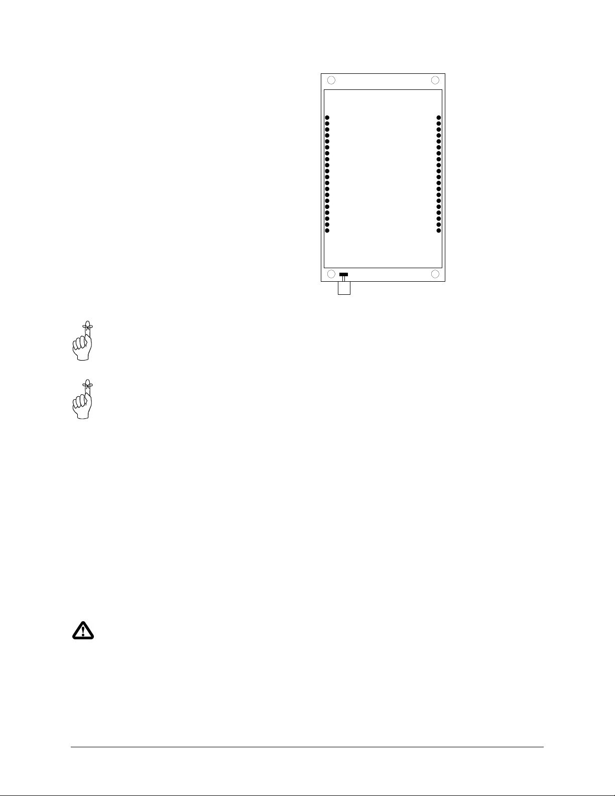
Top View
Tx Mode LED
Rx Mode LED
For maximum power, use
separate power supplies for
the radio and the digital
electronics.
For OEM design simplicity,
connect both the radio and
logic VCC connections
together. This saves a
regulated power supply.
Caution: Using any other power
supply which does not provide the
proper voltage or current could
damage the MHX-900 module.
Vcc Radio
Vcc Radio
Vcc Logic
Vcc Logic
Vcc Logic
Vcc Logic
Vcc Logic
N/C
/CONFIG
/RESET
GND
GND
GND
GND
GND
GND
GND
N/C
N/C
N/C
1
20
Antenna Connector
40
21
N/C
N/C
N/C
N/C
N/C
N/C
N/C
RSSI LED 3
RSSI LED 2
RSSI LED 1
CTS
RTS
DSR
N/C
DTR
TxD
RxD
DCD
The interface connectors and indicator lights are summarized below:
Vcc Radio - These connections supply power for the MHX-900 module’s radio
deck electronics. For 1 watt maximum output, the required supply rating
should be 5.25 VDC +- 5%. Limiting this to 5.0 Vdc will limit the output
power slightly. Required current depends on transmit duration and output
power. Maximum current at full transmit power is 600 mA DC.
Vcc Logic - These connections supply power for the MHX-900 module’s digital
electronics. To simplify the OEM design, the Radio VCC can be
connected to the Logic VCC. Maximum current while transmitting is
approx. 100 mA DC.
GND - These are the Ground supply connections for the digital and radio
electronics.
/RESET - This momentary active low input signal (100 ms typical) resets the
digital electronics.
/CONFIG - Leave this pin unconnected. Do NOT ground.
Receive Signal Strength Indicator (RSSI) LEDs - These outputs show the
quality/strength of the received signal. As the signal strength increases,
the number of active outputs increase incrementally.
Data Port (DCE) - Pins 21 through 28 inclusive. This port is used to interface
the MHX-900 module to a DTE device and operates at 2400 to 115,200
bps. The same port is used to configure the modem by interfacing to the
host microprocessor. See Appendix B for details on the serial interface
signals.
RX Mode LED - This active low output indicates when the modem receives data
over the wireless link, as well as during internal carrier search and
synchronization operations.
TX Mode LED - This active low output indicates that the modem is transmitting
data wirelessly. This light flashes during initial startup and carrier
synchronization.
Antenna Connector - The antenna is attached to this connection.
N/C - These pins are reserved for future use. Do not connect to this pins.
4 MHX-900 Operating Manual: Chapter 2 Initial Setup and Configuration
Page 9
2.3 Configuration
Prior to establishing a wireless link, each MHX-900 module that will
participate in the link must be correctly configured for compatibility and for
the desired mode of operation.
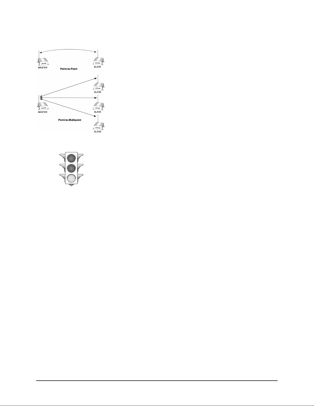
The two most common types of networks used are:
n Point-to-point: A Master station communicates with a single
Slave station.
n Point-to-multipoint: A Master station communications with
two or more Slave stations.
Within any network, the Master will communicate only with Slave(s)
assigned to the same network. Similarly, a Slave will only communicate with
the Master of the network to which it is assigned.
2.3.1 Quick Start Approach
The minimum configuration requirements for point-to-point and point-tomultipoint are summarized below. These requirements will get you started
and only ensure that a link can be established, but do not necessarily provide
the best performance; optimization of the communications link is discussed
in later sections.
A. Point-to-Point
To establish a point-to-point communications link, the following requisites
must be satisfied:
n The Operating Mode for one modem must be configured as a
“Master - Point-to-Point”, and the other as a “ Slave - Point-toPoint”.
n The Wireless Link Rate for both modems must be the same.
n The Network Address assigned for both modems must be the
same.
n The Unit Address assigned for both modems must be the same.
n The same Hopping Pattern must be selected for both modems.
n The same Hopping Interval must be selected for both modems.
n Both modems must use the same Encryption Key.
MHX-900 Operating Manual: Chapter 2 Initial Setup and Configuration 5
Page 10

B. Point-to-Multipoint
To establish a point-to-multipoint network, the following requisites must be
satisfied:
n The Operating Mode for one modem must be configured as a
Point-to-Multipoint Master, and the others as Point-toMultipoint Slaves.
n The Wireless Link Rate for all modems must be the same.
n The Network Address assigned to all modems must be the same.
n Each Slave must be assigned a unique Unit Address (Unit Address
0 is not supported).
n The same Hopping Pattern must be selected for all modems.
n The Hopping Interval is determined by the Master modem, and is
therefore configured only at the Master.
n All modems must use the same Encryption Key.
Each of the parameters above are defined by specific S registers. Settings are
not immediately stored in non-volatile memory. The command &W writes
the current configuration into non-volatile memory, and are therefore retained
even after powering down. Each item and the settable parameters within the
modem configuration are described in detail in Chapter 3: Configuration
Options.
2.4 Checking the Link
Warning: Using an antenna that
is inappropriate for use with the
MHX-900 module could result in
undesired performance, and may
damage the unit. It is the user’s
responsibility to ensure the
antenna has adequate lightning
protection.
Once configured properly, a pair or set of communicating modems can be tested
to ensure that a link can be successfully established. Connect an appropriate
antenna to each MHX-900 module. The modems should indicate the status of
the wireless link via the RSSI outputs on each unit:
If the link is good, up to three RSSI outputs should be active; and if the link
is absent (due to a fault at one end or another, such as misconfiguration), the
outputs will be inactive.
It is recommended that if MHX-900 modules will be deployed in a field
where large distances separate the units, the modems should be configured
and tested in close proximity (e.g., in the same room) first to ensure a good
link can be established and settings are correct. This will facilitate
troubleshooting, should problems arise. In a multipoint system, only the
Slave modems give valid RSSI readings.
Microhard Systems Inc. provides a development system which supplies all
system power and RS-232 level shifting circuits required to connect a MHX900 module to a PC. This can serve as an invaluable aid in OEM system
design.
6 MHX-900 Operating Manual: Chapter 2 Initial Setup and Configuration
Page 11

3. Configuration Options
3.0 Command Line Interface
The MHX-900 modem module is easily configured to meet a wide range of
needs and applications. You can have your modem perform a variety of
functions by sending it instructions (in the form of commands). Sending a
command overrides the modem’s operating characteristics.
Your modem must be in Command Mode for it to execute a command. If
you send characters when the modem is in Data Mode, the modem sends the
characters across the Wireless Link.
When the modem is initially powered up, the interface will operate in
command mode.
You can place the modem into Data Mode either by
1. Dialing a remote modem
2. Issuing the answer command
3. Issuing the online command
You can place the modem into Command Mode either by
1. Sending the escape sequence
2. Toggling the DTR line,
Refer to Appendix A (page
19) for a summary of the
modem commands
Configuration options are
not stored in non-volatile
memory until the WRITE
command (&W) is executed
Note: When the connection is lost to the remote modem, the modem will
switch to command mode.
To enter a command line and have your modem execute it, use the following
procedure:
1. With your modem in the Command Mode, type AT. These characters,
known as the attention characters, must be typed at the beginning or
each command line.
2. Type the command(s) in upper-case letters. Include any parameters
required by the command. To make the command line more readable,
you can insert as many spaces as desired. The command line holds up
to 40 characters, not including the AT prefix.
3. Press the ENTER key. Your modem executes the command line and
sends you a word response (usually OK).
For example, to set the Operating Mode S101 register to Master point to
point mode, enter the following command line; AT S101 = 1 <return>.
To display what a register is currently set to, enter the following command
line; AT Sxxx? <return>. The modem will output the value of the register.
MHX-900 Operating Manual: Chapter 3 Configuration Options 7
Page 12

Note: If you want to send more than one command line, wait for a response
before entering the AT prefix at the start of the next command line.
To re-execute the previous command, enter A/. The modem will execute
the previous command line.
For the AT command protocol, an escape sequence consists of three
consecutive escape codes preceded and followed by at least 1 second of
inactivity. Typically, the ‘+’ character is used as the escape code.
+++ preceded and followed by 1 second of inactivity
3.1 AT Commands
Several AT Commands are supported by the MHX-900 module. The
following is a short description of all available commands. ‘*’ denotes
standard factory settings.
A Answer
The A command causes the modem to attempt to connect with another
remote modem.
D Dial
Using the D command, the modem will set itself for master point to point
mode, and then try to synchronize with the modem address specified in the
command (Dxxxx). Register S105 is overwritten with value xxxx. Note DT or DP are also value (tone dial or pulse dial).
E Command Echo
Your modem is preset to return (or echo) commands to the host
microprocessor when in Command Mode.
E0 No Command Echo
*E1 Command Echo
I Identification
The I command returns various modem information settings.
I0 Product Code (MHX-900)
I1 3 Digit computed checksum
I2 Issue ROM Check (OK or ERROR)
I3 Product Identification (Firmware Version)
I4 Not Supported
I5 Firmware Copyright
O On-line Mode
The O command attempts to communicate with a remote modem.
8 MHX-900 Operating Manual: Chapter 3 Configuration Options
Page 13

Q Quiet Mode
Your modem is preset to send responses when it executes commands, and
there after to keep the host informed of its status.
*Q0 Enable modem responses
Q1 Disable modem responses
V Result Codes display
Your modem can either display result codes as words or numbers.
V0 Display Result Codes as numbers
*V1 Display Result Codes as words
W Connection Result
The W command returns your modem to the Data Mode from the Command
Mode
*W0 Reports computer (DTE) rate as CONNECT xxxx
W1 Reports computer (DTE) rate and wireless rate between
modems as CARRIER xxxx.
W2 Reports modem (DCE) rate as CONNECT xxxx
Z Reset and load stored configuration
The Z command resets the modem and loads the stored configuration.
&C DCD (Data Carrier Detect)
The &C command controls the modems DCD output signal to the host
microprocessor. This command determines when the DCD is active.
&C0 DCD is always ON
*&C1 DCD on when modems are synchronized
&D DTR (Data Terminal Ready)
The &D command controls what action the modem performs when the DTR
input line is toggled. The DTR input is controlled by the host
microprocessor.
&D0 DTR line is ignored
&D1 Not Supported
*&D2 DTR disconnects and switches to Command Mode
&D3 DTR disconnects and resets modem
&F Load Factory Default Configuration
The &F command resets the modem and loads the default factory
configuration.
&K Handshaking
The &K command controls the handshaking between the modem and host
microprocessor.
&K0 Disable handshaking
*&K3 Enable hardware handshaking (RTS/CTS)
MHX-900 Operating Manual: Chapter 3 Configuration Options 9
Page 14

&S DSR (Data Set Ready)
The &S command controls the DSR line for the modem, and determines
when it is active
&S0 DSR is always ON
*&S1 DSR is ON in Data Mode, OFF in Command Mode
&V View Configuration
The &V command displays the current (DTE) baud rate, and all setable
modem parameters including S register values.
&W Write Configuration to memory
The &W command stores the active configuration into the modem’s nonvolatile memory.
Sxxx? Read S register value
This command causes the modem to display the current setting of S register
xxx.
Sxxx=yyy Set S register value (see section on S-Registers)
This command sets the specified S register to a value specified by yyy.
3.2 Command Result Codes
The MHX-900 module can either display the results of a command as either
text strings or numerical data. The following chart shows resulting text
string and corresponding numeric result.
0 OK
1 CONNECT
2 RING
3 NO CARRIER
4 ERROR
8 NO ANSWER
10 CONNECT 2400
11 CONNECT 4800
12 CONNECT 9600
14 CONNECT 19200
17 CONNECT 38400
18 CONNECT 57600
33 CONNECT 115200
10 MHX-900 Operating Manual: Chapter 3 Configuration Options
Page 15

3.3 S Registers
S Register 0 - Number of Rings - Auto Answer
If this register is set to zero, the modem will power up in command mode. If
this register is non-zero, the modem will power up in data mode.
S Register 2 - Escape Code
This register contains the ASCII value of the escape character.
The default value (decimal 43) is equivalent to the ASCII character ‘+’.
Values greater than 127 disable the escape feature and prevent you from
returning to the Command Mode.
Default is ‘+’ (decimal 43).
S Register 3 - CR Control Code
This register contains the ASCII value of the carriage return character.
This is the character that is used to end the command line and is also the
character that appears after the modem sends a response.
Default is ‘CR’ (decimal 13).
S Register 4 - Linefeed Control Code
Register S4 sets the ASCII value of the linefeed character.
The modem sends the linefeed character after sending a carriage return
character when sending text responses.
Default is ‘LF’ (decimal 10).
S Register 5 - Backspace Control Code
Register S5 sets the ASCII value of the backspace character.
This character is both the character created by entering BACKSPACE and
the character echoed to move the cursor to the left.
Default is ‘BS’ (decimal 8).
MHX-900 Operating Manual: Chapter 3 Configuration Options 11
Page 16

Each unit must be either a
Master or Slave.
Only one Master can exist
for each network.
S Register 101 - Operating Mode
The Operating Mode (register S101) partly defines the “personality” of the
MHX-900 module. Allowable settings for this register are 1 through 4.
Default is 2 (Slave point to point).
Each unit should be configured as a Master or Slave. The user should
decide, prior to deployment, whether a point-to-point or point-to-multipoint
network is appropriate for the application, and how each unit will be
assigned to terminals.
1)Master - Point to Point One unit in a point-to-point link
should be set as the Master, obligating the other modem to be used as a
Slave. During operation, it makes little difference which end is which,
especially if data is generally transmitted unidirectionally at any given
moment. When both terminals have data to send, more bandwidth is
dynamically allocated to the Master; otherwise, the transmitting end,
whichever it is at the time, is given the full bandwidth.
* 2)Slave - Point to Point The terminal in a point-to-point
network which is not set as the Master, is obligated to be the Slave. The
Slave will communicate with the Master, whose network address, unit
address, hopping pattern and hopping interval matches its own.
In point-to-point operation, the Slave modem acknowledges all packets of
data sent by the Master, and vice versa. These acknowledgements, along
with CRC error checking ensure that data is passed through exactly once,
and that the data is not corrupted.
3)Master - Point to Multipoint In a point-to-multipoint
network, one unit should be set as the Master, obligating all other modems
to be Slaves. The Master designation is generally given to the station which
functions as a hub for all remote nodes, and it is the Master station’s
responsibility to control communications with Slaves.
Point-to-multipoint operation differs from point-to-point operation in many
ways. One key difference is that the Slaves cannot acknowledge packets of
data sent by the Master. Clearly this would cause conflicts when there are
multiple Slaves. The Master does, however, send acknowledgements to all
messages it receives from Slaves. The Master initiates communications by
sending a broadcast message to all Slaves. All Slaves are free to respond in
a “Slotted ALOHA” fashion, meaning that each Slave can choose one of
several windows in which to transmit. If there happens to be two Slaves
attempting to talk at the same time, then the Master would not receive the
data, and the Slaves therefore would not get an acknowledgement. At this
point, the Slaves would attempt to get the information through at random
time intervals, thus attempting to avoid any more conflicts. Special
parameters related to Point-to-Multipoint operation are set in the Packet
Parameters menu, and are described in a later section.
4) Slave - Point to Multipoint Several Slaves exist in a
point-to-multipoint network, all of which communicate with the common
Master. Slaves cannot directly communicate with other Slaves.
12 MHX-900 Operating Manual: Chapter 3 Configuration Options
Page 17

S Register 102 - Serial Baud Rate
The Serial Baud Rate is the current speed that the modem is using to
communicate with the DTE. When the AT command prefix is issued, the
modem performs an ‘autobaud’ operation and determines what the current
DTE baud rate is set to. The S register value returns the current setting of
the DTE baud rate.
The possible values are:
1 115200
2 57600
3 38400
4 28800
5 19200
6 14400
*7 9600
8 7200
9 4800
10 3600
11 2400
It is generally advisable to choose the highest rate that your terminal
equipment will handle to maximize performance, unless a limitation on the
available bandwidth is desired. If the DTE is a personal computer, the port
can usually be used reliably at 115200.
All units in a network must
be set to the same wireless
link rate.
S Register 103 - Wireless Link Rate
The Wireless Link Rate is the speed and optimization method for which
modems will communicate over the RF link.
The allowable settings are:
* 1 Turbo
2 Fast
3 Normal
Depending on the application requirements, each mode will provide
different throughputs and performance optimizations as follows:
Mode
Turbo 96 kbps Optimized for Speed
Fast 60 kbps Optimized for Distance and Speed
Normal 30 kbps Optimized for Distance
Generally, the lowest rate which provides sufficient bandwidth should be
selected. For example, if DTEs are set to communicate at 19.2 kbps, then
the wireless rate can be set to Normal (with the added advantage of slightly
greater range). If DTEs require nearly 115.2 kbps of sustained bandwidth,
then the wireless rate should be set to Turbo (setting it lower would
“bottleneck” data transmissions in the wireless link). Note that there is a
compromise between speed, performance and range.
Expected Performance
(Maximum Throughput)
Primary Optimization
MHX-900 Operating Manual: Chapter 3 Configuration Options 13
Page 18

Select a Network Address
and assign it to all units
which will be included in the
network.
Use the same Unit Address
on both units for point-topoint mode. In multipoint
mode, set all Slaves to a
unique Unit Address.
In Point-to-Point, valid Unit
Addresses are 0 to 65535. In
Point-to-Multipoint, valid
Slave Unit Addresses are 1
to 65535.
S Register 104 - Network Address
The Network Address defines the membership to which individual units can
be a part of. By establishing a network under a common Network Address,
the network can be isolated from any other concurrently operating network
using the same hardware. As well, the Network Address provides a measure
of privacy and security. Only those units which are members of the network
will participate in the communications interchange. Valid values for the
Network Address range from 0 to 65535, inclusive.
To enhance privacy and reliability of communications where multiple
networks may operate concurrently in close proximity, it is suggested that an
atypical value be chosen – perhaps something meaningful yet not easily
selected by chance or coincidence.
Default is 0.
S Register 105 - Unit Address
In point-to-point operation, the Unit Address on both the Master and Slave
units must be the same. In point-to-point operation, valid Unit Addresses
range from 0 to 65535. In a multipoint system, the Unit Address uniquely
identifies each Slave from the others.. In a multipoint system, a Slave can
take on any Unit Address between 1 and 65535.
Remember that each Slave should have a Unit Address which is unique from
any other Slave in the network.
Default is 1.
Ensure that all units within a
network use the same
hopping pattern, and that
multiple concurrent networks
each have different hopping
patterns.
All units within a network
must use the same
encryption key.
S Register 106 - Hopping Pattern
Since the MHX-900 is a frequency-hopping modem, the carrier frequency
changes periodically according to one of twenty pseudo-random patterns,
selected by defining the Hopping Pattern.
A value from 1 to 20, inclusive, can be used to select the pattern. It is
important that all units which will participate in a network use the same
hopping pattern, or the communication link will fail.
Default is 1.
S Register 107 - Encryption Key
The Encryption Key provides a measure of security and privacy of
communications by rendering the transmitted data useless without the
correct key on the receiver. Valid Encryption Keys range from 0 to 65535.
Keep in mind that all units within the network must use the same key for
communications to succeed.
14 MHX-900 Operating Manual: Chapter 3 Configuration Options
Page 19

S Register 108 - Output Power Level
The Output Power Level determines at what power the MHX-900 transmits.
The super-sensitive MHX-900 can operate with very low power levels, so it
is recommended that the lowest power necessary is used; using excessive
power contributes to unnecessary “RF pollution”.
The allowable settings are:
* 1 1 mW
2 10 mW
3 100 mW
4 1000 mW
Ideally, you should test the communications performance between units
starting from a low power level and working upward until the RSSI is
sufficiently high and a reliable link is established. Although the conditions
will vary widely between applications, typical uses for each setting are
described below:
Test the communications
link using a low power level
and work upward. Avoid
using a higher power than
necessary since performance
may actually degrade.
Power Use
1 mW
10 mW
100 mW
1000 mW
(1 W)
For in-building use, typically provides a link up to 300 feet on the
same floor or up/down a level. Outdoors, distances of 10 km can be
achieved if high-gain (directional) antennas are placed high above
ground level and are in direct line-of-sight.
200-500 ft indoors, 8-15 km outdoors.
400-800 ft indoors, 15-25 km outdoors.
Typically provides communications up to a distance of 1000 feet or
more in-building on the same floor or up/down a few levels,
depending on building construction (wood, concrete, steel, etc.). In
ideal line-of-sight conditions, up to 30 km or more can be achieved.
Note that only an antenna with a gain of no more 6 dBi may be used.
Any higher is a violation of FCC rules. See IMPORTANT warning
below.
IMPORTANT:
FCC and Industry Canada Regulations allow up to 36 dBi effective
radiated power (ERP). Therefore, the sum of the transmitted power (in
dBm), the cabling loss and the antenna gain cannot exceed 36 dBi.
1 mW = 0 dBm
10 mW = 10 dBm
100 mW = 20 dBm
1000 mW = 30 dBm
For example, when transmitting 1 Watt (30 dBm), with cabling losses of
2 dB, the antenna gain cannot exceed 36 - 30 + 2 = 8 dBi. If an antenna
with a gain higher than 8 dBi were to be used, the power setting must
be adjusted appropriately.
Violation of FCC or IC regulations can result in severe fines. It is
the responsibility of the user to understand and ensure compliance
with these regulations.
MHX-900 Operating Manual: Chapter 3 Configuration Options 15
Page 20

S Register 109 - Hopping Interval
In a point-to-point network,
the master and slave must be
set to the same hopping
interval.
In a point-to-multipoint
network, the hopping
interval is controlled by the
master. The slave units will
use the hopping interval
setting from the master.
This option determines the frequency at which the modems change channel.
Note that all modems must have the same hopping interval setting.
The allowable settings are:
1 25 msec
2 50 msec
3 100 msec
4 150 msec
*5 200 msec
6 250 msec
7 300 msec
8 350 msec
In Slave - Point-to-Multipoint operation, this parameter is determined by the
Master, and cannot be altered.
Packet Parameters
Packet Parameters define the characteristics of the internal packets or frames
which are transmitted. The settings should be set only by an expert since
adequate care must be taken to maintain reliability and optimum
performance. Packet Parameters will vary depending on the modem’s
Operating Mode.
S Registers 111 to 113 - Packet Parameters -Point to Point
Mode
In Point-to-Point (both Master and Slave), the following settings are
available:
S Register 111 - Minimum Size
This setting has a range of 0 to 255, and defines the number of bytes to
accumulate from the DTE before transmitting a packet. Setting this value to
0 ensures that all characters sent by the DTE are immediately transmitted.
The value may not exceed the maximum packet size.
S Register 112 - Maximum Size
This setting has a range of 1 to 255, and defines the maximum number of
bytes from the DTE which should be encapsulated in a packet. This value
should be greater than the minimum packet size, but not smaller than is
necessary for reliable communications. If the wireless link is consistently
good and solid, a maximum size of 255 will yield the best throughput
(depending on the higher level protocols of the connected equipment).
However, if the link is poor (e.g., experiencing excessive interference) and
data is frequently retransmitted, the maximum packet size should be
reduced. This decreases the probability of errors within packets, and
reduces the amount of traffic in the event that retransmissions are required.
Since a smaller packet size results in a proportionally higher overhead and
lower overall throughput on a good connection, this should only be reduced
if many errors are being detected by CRC (see Radio Statistics option of
configuration).
16 MHX-900 Operating Manual: Chapter 3 Configuration Options
Page 21

S Register 113 - Retry Limit
This setting has a range of 0 to 255, and determines the number of attempts
that will be made to retransmit data which failed the CRC checksum. Once
the limit is reached, the modem will give up and discard the data. If the
wireless connection is poor and data often needs to be retransmitted, a
modem could be “tied up” trying to retransmit, thus holding up pending
data.
S Registers 111 to 115 - Packet Parameters - Point-toMultipoint Mode
If the Operating Mode is Slave - Point-to-Multipoint, the default values for
the S registers are:
S111 Minimum Size (not used)
S112 Maximum Size (not used)
S113 Retry Limit 4
S115 Repeat Interval 8
In Master - Point-to-Multipoint mode, the default values for the S registers
are:
S111 Minimum Size 0
S112 Maximum Size 255
S113 Retransmissions 255
S114 Address Header Disabled
S Register 111 - Minimum Size
The Minimum Size parameter prevents the Slave from sending data until it
has buffered a minimum number of bytes. The Master determines this
parameter and passes the information to all Slaves in a Multipoint system.
S Register 112 - Maximum Size
Packet sizes in excess of the minimum size are limited by the Maximum
Size parameter. If the Slave is sending more than the minimum, the unit will
wait until it has buffered the maximum packet size or until a packet timeout
of two characters occurs on the serial port. The Master unit tells all Slaves
which maximum and minimum packet values to use. In addition, the Master
tells all Slaves which Hopping Interval to use (see Section 3.11).
S Register 113 - Retry Limit (Slave Point to
Multipoint)
Similar to the Retry Limit in Point-to-Point, the Slaves in a multipoint
system will reattempt to send a packet of data until it receives an
acknowledge or until it reaches the Retry Limit.
MHX-900 Operating Manual: Chapter 3 Configuration Options 17
Page 22

S Register 113 - Retransmissions (Master Point to
Multipoint)
In a multipoint system, the Master does not receive acknowledgments from
Slaves, and therefore has a slightly modified parameter called
Retransmissions. The Master will retransmit each data packet exactly the
number of times defined by the Retransmissions parameter. The Master
retransmits once per hopping interval until the limit is reached.
S Register 114 - Address Header
A packet parameter unique to Master - Point-to-Multipoint is the Address
Header parameter. The allowable settings are:
*1 Disabled
2 Binary
3 Text
When the Master receives a packet from a Slave, it has the option of
attaching an address header at the beginning of each packet.
Option 2 will attach two bytes of binary data that represent the Slave Unit
Address. The first byte is MSB.
Option 3 will attach five bytes of data that represent the text version of the
Slave Unit Address. The Maximum Packet Size includes the Address
Header. For example, if the Maximum Packet Size is set to 128 and the
Text Address Header option is selected, then the Master will tell the Slave
to send a maximum of 123 bytes.
No address header is attached when Option 1) is used. In this case, it is up
to the equipment connected to the Slave to attach an address header of some
sort so that the Master equipment can determine the source of the data
transmission.
S Register 115 - Packet Repeat Interval
A parameter that is specific to the Slave in multipoint operation is the
Repeat Interval.
The allowable settings are:
1 1...1
2 1...3
3 1...7
4 1...15
5 1...31
6 1...63
7 1...127
*8 1...255
This parameter defines a range of random numbers that the Slave will use as
the next slot in which it will attempt to send the packet. For example, if
Option 3 (1...7) is selected, and the random number generator picks 5, then
the Slave will transmit after five time slots. A Slave will transmit a
maximum of once per hopping interval. The Slave will transmit more
frequently when a Repeat Interval with a smaller range is selected. Choose
1) for the most frequent repeats and choose 8) for the least frequent repeats.
18 MHX-900 Operating Manual: Chapter 3 Configuration Options
Page 23

A. Modem Command Summary
The following provides a command summary for the MHX-900 module. Factory settings are denoted with a ‘*’.
AT Commands
A Answer
D Dial
E Command Echo
E0 No Echo
* E1 Command Echo
I Identification
I0 Product Code
I1 Checksum
I2 ROM Checksum
I3 Product ID
I4 Not Supported
I5 Firmware Version
O On-line Mode
Q Quiet Mode
* Q0 Enables Result Codes
Q1 Disables Result Codes
V Result Codes Display
V0 Display as Numbers
* V1 Display as Words
W Connection Result
* W0 Reports DTE as CONNECT xxxx
W1 Reports computer (DTE) rate and wireless
rate between modems as CARRIER xxxx.
W2 Reports DCE as CONNECT xxxx
Z Reset and load stored configuration
&C DCD (Data Carrier Detect)
&C0 DCD is always on
* &C1 DCD is on when modems are
synchronized
&D DTR (Data Terminal Ready)
&D0 DTR ignored
* &D2 DTR disconnects and switches to
command
&D3 DTR disconnects and resets modem
&F Load Factory Default
&K Handshaking
&K0 Disable Handshaking
* &K3 Enable Handshaking
&S DSR (Data Set Ready)
&S0 DSR is always on
* &S1 DSR on in data, off in command mode
&V View Configuration
&W Write configuration to memory
Sxx? Read S register value
Sxx=yy Set S register value
Result Codes
0 OK
1 CONNECT
2 RING
3 NO CARRIER
4 ERROR
8 NO ANSWER
10 CONNECT 2400
11 CONNECT 4800
12 CONNECT 9600
14 CONNECT 19200
17 CONNECT 38400
18 CONNECT 57600
33 CONNECT 115200
S Registers
S0 Number of Rings - Auto Answer [0...255]
S2 Escape code [0...255] default ‘+’
S3 CR character [0...255] default <cr>
S4 Line Feed [0...255] default <lf>
S5 Backspace [0...255] default <bs>
S101 Operating Mode
1 - Master point to point
* 2 - Slave point to point
3 - Master point to multipoint
4 - Slave point to multipoint
S102 Serial Baud Rate
1 = 115200, 2 = 57600, 3 = 38400
4 = 28800, 5 = 19200, 6 = 14400
* 7 = 9600, 8 = 7200, 9 = 4800,
10 = 3600, 11 = 2400
S103 Wireless Link Rate
*1 = Turbo, 2 = Fast, 3 = Normal
S104 Network Address [0...65535]
S105 Unit Address [0...65535]
S106 Hopping Pattern [1...20]
S107 Encryption Key [0...65535]
S108 Output Power Level
* 0 = 1 mW, 1 = 10 mW, 2 = 100 mW
3 = 1000 mW
S109 Hopping Interval
1 = 25 msec, 2 = 50 msec, 3 = 100 msec,
4 = 150 msec, * 5 = 200 msec, 6 = 250 msec,
7 = 300 msec, 8 = 350 msec
S111 Packet Minimum Size [0...Maximum Size]
S112 Packet Maximum Size [1...255]
S113 Packet Retry Transmissions [0...255]
S114 Address Header
* 0 = Disabled, 1 = Binary, 2 = Text
S115 Packet Repeat Interval
1 = 1...1, 2 = 1...3, 3 = 1...7, 4 = 1...15
5 = 1...31, 6 = 1...63, 7 = 1...127, * 8 = 1...255
MHX-900 Operating Manual: Appendix A Modem Command Summary 19
Page 24

20 MHX-900 Operating Manual: Appendix A Modem Command Summary
Page 25

Modem
Signal
DCD
RX
TX
DTR
SG
DSR
RTS
CTS
Microprocessor
(DTE)
→
→
OUT
OUT
→
OUT
→
(DCE)
21
22
23
←
24
←
17
26
27
←
28
Arrows denote the direction that
signals are asserted (e.g., DCD
originates at the DCE and tells the
DTE that a carrier is present).
Host
IN
IN
IN
IN
B. Serial Interface
The MHX-900 module uses 8 pins on the 40 pin connector for asynchronous
serial I/O. The interface conforms to TTL level RS-232 signals (ie. without
level shifting), so direct connection to a host microprocessor is possible.
The signals in the asynchronous serial interface are described below:
DCD Data Carrier Detect - Output from Modem - When asserted (TTL low),
DCD informs the DTE that a communications link has been established with
another MHX-900.
RX Receive Data - Output from Modem - Signals transferred from the MHX-
900 are received by the DTE via RX.
TX Transmit Data - Input to Modem - Signals are transmitted from the DTE via
TX to the MHX-900.
DTR Data Terminal Ready - Input to Modem - Asserted (TTL low) by the DTE to
inform the modem that it is alive and ready for communications.
SG Signal Ground - Provides a ground reference for all signals transmitted by
both DTE and DCE.
DSR Data Set Ready - Output from Modem - Asserted (TTL low) by the DCE to
inform the DTE that it is alive and ready for communications. DSR is the
modem’s equivalent of the DTR signal.
RTS Request to Send - Input to Modem - A “handshaking” signal which is
asserted by the DTE (TTL low) when it is ready. When hardware
handshaking is used, the RTS signal indicates to the DCE that the host can
receive data.
CTS Clear to Send - Output from Modem - A “handshaking” signal which is
asserted by the DCE (TTL low) when it has enabled communications and
transmission from the DTE can commence. When hardware handshaking is
used, the CTS signal indicates to the host that the DCE can receive data.
Notes: It is typical to refer to RX and TX from the perspective of the DTE. This should be
kept in mind when looking at signals relative to the modem (DCE); the modem
transmits data on the RX line, and receives on TX.
“DCE” and “modem” are often synonymous since a modem is typically a DCE device.
“DTE” is, in most applications, a device such as a host microprocessor.
MHX-900 Operating Manual: Appendix B Serial Interface 21
Page 26

22 MHX-900 Operating Manual: Appendix B Serial Interface
Page 27

C. Sample Schematic Diagram
RXD
TXD
DCD
DTR
DSR
RTS
CTS
RESET
PIC16C74
MHX-900
22232124262728
10
Power Connections are not shown
RC7
RC6
RD0
RD1
RD2
RD3
RD4
RD6
The following is a sample microprocessor implementation with a MICROCHIP PIC 16C74 and the MHX-900. The MHX-900
performs no level shifting on the serial port, so direct connection to the host microprocessor is possible.
DO NOT CONNECT THE MHX-900 TO RS 232 DRIVER OUTPUTS. DAMAGE TO THE UNIT MAY RESULT.
On this implementation, the onboard SCI of the PIC 16C74 is directly connected pins 22 and 23 of the MHX-900. The bidirectional Port D is used for asserting or monitoring control signals from the MHX-900.
The RESET signal is a momentary active low signal asserted by the host microprocessor.
RESET initializes the MHX-900 and places the system in a known state. This signal should be set high after the host
microprocessor has been reset.
MHX-900 Operating Manual: Appendix C Sample Schematic Diagram 23
Page 28

24 MHX-900 Operating Manual: Appendix C Sample Schematic Diagram
Page 29

D. Modem Setup Overview
The required commands required to setup an MHX-900 module for point-to-point and point-to-multipoint are
summarized below. These requirements will get you started and only ensure that a link can be established, but do
not necessarily provide the best performance.
Point-to-Point
To establish a point-to-point communications link, the following commands must be issued by the host EOM
microprocessor:
n The Operating Mode S Register (S101) for one modem must be configured as a “Master - Point-to-Point”
(1), and the other as a “ Slave - Point-to-Point” (2).
n The Wireless Link Rate S Register (S103) value for both modems must be the same.
n The Network Address S Register (S104) value assigned for both modems must be the same.
n The Unit Address S Register (S105) value assigned for both modems must be the same.
n The same Hopping Pattern S Register (S106) value must be selected for both modems.
n The same Hopping Interval S Register (S109) value must be selected for both modems.
n The same Encryption Key S Register (S107) value must be selected for both modems.
The master can now attempt to synchronize with the slave using the D<slave address> command.
Point-to-Multipoint
To establish a point-to-point communications link, the following commands must be issued by the host OEM
microprocessor:
n The Operating Mode S Register (S101) for one modem must be configured as a “Point-to-Multipoint
Master ” (3), and the other as a “Point-to-Multipoint Slave” (4).
n The Wireless Link Rate S Register (S103) value for both modems must be the same.
n The Network Address S Register (S104) value assigned for both modems must be the same.
n Each Slave must be assigned an unique Unit Address S Register (S105) value (Unit Address 0 is not
supported).
n The same Hopping Pattern S Register (S106) value must be selected for both modems.
n The same Hopping Interval S Register (S109) value must be selected for both modems.
n The same Encryption Key S Register (S107) value must be selected for both modems.
The master can now attempt to synchronize with the slave using the D<slave address> command.
MHX-900 Operating Manual: Appendix D Modem Setup Overview 25
Page 30

26 MHX-900 Operating Manual: Appendix D Modem Setup Overview
Page 31

E. Technical Specifications
Electrical/Physical
Data Interface Asynchronous Serial Port, TTL Levels
RS-232 Signals Sig. Gnd, TX, RX, DCD, DSR, DTR, RTS, CTS
Other Signals Reset, RxMode, TxMode, RSSI1, RSSI2, RSSI3
(All except Reset are status signals)
User Interface AT Command line interface
Bandwidth / Data Rate 2,400 - 115,200 bps, uncompressed half-duplex,
Approx. 100 kbps sustained in intelligent asymmetrical full-duplex
transmission mode
Communications Range Up to 30 kilometres (19 miles) line of sight
Power Requirements 4.75 to 5.5 VDC
Power Consumption 5500 mA at 1 W transmit, 220 mA receive
Operating Frequency 902 - 928 MHz
System Gain 135 dB
Sensitivity -105 dBm
Output Power 1mW, 10mW, 100mW, 1W (user-selectable)
Spreading Code Frequency Hopping
Hopping Patterns 20 pseudo-random, user-selectable
Error Detection CRC-16 with auto re-transmit
Dimensions (WxDxH)
Weight 75 grams
Operating Environment Temperature: -40 to +65°C
Encl: 2.1” x 3.5” x 0.75” (53 mm x 89 mm x 19 mm)
Humidity: 5 to 95%, non-condensing
MHX-900 Operating Manual: Appendix E Technical Specifications 27
Page 32

28 MHX-900 Operating Manual: Appendix E Technical Specifications
Page 33

F. Glossary
Terminology Used in the MHX-900 Operating Manual
Asynchronous communications A method of
telecommunications in which units of single bytes
of data are sent separately and at an arbitrary time
(not periodically or referenced to a clock). Bytes
are “padded” with start and stop bits to distinguish
each as a unit for the receiving end, which need
not be synchronized with the sending terminal.
Attenuation The loss of signal power through
equipment, lines/cables, or other transmission
devices. Measured in decibels (dB).
Bandwidth The information-carrying capacity of a
data transmission medium or device, usually
expressed in bits/second (bps).
Baud Unit of signaling speed equivalent to the
number of discrete conditions or events per
second. If each signal event represents only one
bit condition, then baud rate equals bits per
second (bps) – this is generally true of the serial
data port, so baud and bps have been used
interchangeably in this manual when referring to
the serial port; this is not always the case during
the DCE-to-DCE communications, where a
number of modulation techniques are used to
increase the bps rate over the baud rate.
Bit The smallest unit of information in a binary
system, represented by either a 1 or 0.
Abbreviated “b”.
Bits per second (b/s or bps) A measure of data
transmission rate in serial communications. Also
see baud.
Byte A group of bits, generally 8 bits in length. A
byte typically represents a character of data.
Abbreviated “B”.
Characters per second (cps) A measure of data
transmission rate for common exchanges of data.
A character is usually represented by 10 bits: an 8bit byte plus two additional bits for marking the
start and stop. Thus, in most cases (but not
always), cps is related to bits per second (bps) by
a 1:10 ratio.
CRC (Cyclic Redundancy Check) An error-detection
scheme for transmitted data. Performed by using
a polynomial algorithm on data, and appending a
checksum to the end of the packet. At the
receiving end, a similar algorithm is performed
and checked against the transmitted checksum.
Crossover cable (Also known as rollover, null-
modem, or modem-eliminator cable) A cable
which allows direct DTE-to-DTE connection
without intermediate DCEs typically used to
bridge the two communicating devices. Can also
be used to make cabled DCE-to-DCE connections.
The name is derived from “crossing” or “rolling”
several lines, including the TX and RX lines so
that transmitted data from one DTE is received on
the RX pin of the other DTE and vice-versa.
Data Communications Equipment (DCE, also
referred to as Data Circuit-Terminating
Equipment, Data Set) A device which facilitates a
communications connection between Data
Terminal Equipment (DTEs). Often, two or more
compatible DCE devices are used to “bridge”
DTEs which need to exchange data. A DCE
performs signal encoding, decoding, and
conversion of data sent/received by the DTE, and
transmits/receives data with another DCE.
Common example is a modem.
Data Terminal Equipment (DTE) An end-
device which sends/receives data to/from a DCE,
often providing a user-interface for information
exchange. Common examples are computers,
terminals, and printers.
dBm Stands for “Decibels referenced to one
milliwatt (1 mW)”. A standard unit of power
level commonly used in RF and communications
work. n dBm is equal to 10
0dBm = 1mW, -10dBm = 0.1mW, -20dBm =
0.01mW, etc.
DCE See Data Communications Equipment.
DTE See Data Terminal Equipment.
Flow Control A method of moderating the
transmission of data so that all devices within the
communications link (DTEs and DCEs) transmit
and receive only as much data as they can handle
at once. This prevents devices from sending data
which cannot be received at the other end due to
conditions such as a full buffer or hardware not in
a ready state. This is ideally handled by hardware
using flow-control and handshaking signals, but
(n/10)
milliwatt, so
MHX-900 Operating Manual: Appendix F Glossary 29
Page 34

can be controlled also by software using X-ON/XOFF (transmitter on/off) commands.
Frequency-hopping A type of spread spectrum
communication whereby the carrier frequency
used between transmitter and receiver changes
repeatedly in a synchronized fashion according to
a specified algorithm or table. This minimizes
unauthorized jamming (interference) and
interception of telecommunications.
Full-duplex Where data can be transmitted,
simultaneously and independently, bidirectionally.
Half duplex Exists when the communications
medium supports bi-directional transmission, but
data can only travel in one direction at the same
time.
Handshaking A flow-control procedure for
establishing data communications whereby
devices indicate that data is to be sent and await
appropriate signals that allow them to proceed.
Line-of-sight Condition in which a transmitted
signal can reach its destination by travelling a
straight path, without being absorbed and/or
bounced by objects in its path.
Master The station which controls and/or polls one
or more Slave stations in a point-to-point or pointto-multipoint network. Often functions as a server
or hub for the network.
Non-volatile memory Memory which retains
information which is written to it.
Null modem cable See Crossover cable.
Point-to-point A simple communications network
in which only two DTEs are participants.
Point-to-multipoint A communications network
in which a Master DTE communicates with two or
more Slave DTEs.
Repeater A device which automatically amplifies
or restores signals to compensate for distortion
and/or attenuation prior to retransmission. A
repeater is typically used to extend the distance
for which data can be reliably transmitted using a
particular medium or communications device.
RS-232 (Recommended Standard 232; more
accurately, RS-232C or EIA/TIA-232E) Defined
by the EIA, a widely known standard electrical
and physical interface for linking DCEs and DTEs
for serial data communications. Traditionally
specifies a 25-pin D-sub connector, although
many newer devices use a compact 9-pin
connector with only the essential signaling lines
used in asynchronous serial communications.
Lines have two possible states: “high” (on, active,
asserted, carrying +3 to +25 V) or “low” (off,
inactive, disasserted, carrying -3 to -25 V).
RTU (Remote Terminal Unit) A common term
describing a DTE device which is part of a widearea network. Often a RTU performs data I/O and
transmits the data to a centralized station.
Serial communications A common mode of
data transmission whereby character bits are sent
sequentially, one at a time, using the same
signaling line. Contrast with parallel
communications where all bits of a byte are
transmitted at once, usually requiring a signal line
for each bit.
Shielded cable Interface medium which is
internally shrouded by a protective sheath to
minimize external electromagnetic interference
(“noise”).
Slave A station which is controlled and/or polled by
the Master station for communications. Typically
represents one end of a point-to-point connection,
or one of the terminal nodes in a point-tomultipoint network. Often a RTU is linked by a
Slave DCE.
Spread spectrum A method of transmitting a
signal over a wider bandwidth (using several
frequencies) than the minimum necessary for the
originally narrowband signal. A number of
techniques are used to achieve spread spectrum
telecommunications, including frequency hopping.
Spread spectrum provides the possibility of
sharing the same band amongst many users while
increasing the tolerance to interference and noise,
and enhancing privacy of communications.
Throughput A measure of the rate of data trans-
mission passing through a data communication
system, often expressed as bits or characters per
second (bps or cps).
30 MHX-900 Operating Manual: Appendix F Glossary
 Loading...