


Contents
1. Introduction
1.0 Product Overview ....................................................................................................................................... 1
1.1 Features....................................................................................................................................................... 1
1.2 About this Manual....................................................................................................................................... 2
2. Initial Installation and Setup
2.0 Unpacking and Inspection........................................................................................................................... 3
2.1 Additional Requirements ............................................................................................................................ 3
2.2 Connectors and Indicators........................................................................................................................... 4
2.3 Hardware Setup........................................................................................................................................... 4
2.4 Configuration.............................................................................................................................................. 5
2.4.1 Quick Start Approach....................................................................................................................... 5
A. Point-to-Point ............................................................................................................................. 5
B. Point-to-Multipoint..................................................................................................................... 6
3. Configuration Options
3.0 Changing Parameters in Configuration Menu............................................................................................. 7
3.1 Operating Mode.......................................................................................................................................... 7
3.2 Serial Baud Rate ......................................................................................................................................... 9
3.3 Wireless Link Rate...................................................................................................................................... 9
3.4 Network Address....................................................................................................................................... 10
3.5 Unit Address ............................................................................................................................................. 10
3.6 Hopping Pattern........................................................................................................................................ 10
3.7 Encryption Key......................................................................................................................................... 11
3.8 Output Power Level.................................................................................................................................. 11
3.9 Packet Parameters..................................................................................................................................... 12
3.10 Radio Statistics.......................................................................................................................................... 13
3.11 Slave List .................................................................................................................................................. 13
Appendices
A. MRX-900 Configuration Menu Navigation Chart................................................................ 15
B. Configuration Record............................................................................................................ 17
C. RS-232 Interface and Cables
C.0 RS-232 Line Signals ................................................................................................................................. 19
C.1 DTE-to-DCE (Straight-Through) Cables.................................................................................................. 19
C.2 Crossover / Null Modem Cables............................................................................................................... 20
C.3 Loopback Plug.......................................................................................................................................... 20
D. Surface or Wall Mounting..................................................................................................... 21
E. Troubleshooting..................................................................................................................... 23
F. Technical Specifications........................................................................................................ 25
G. Glossary................................................................................................................................. 27
MRX-900 Operating Manual: Contents i

ii MRX-900 Operating Manual
1. Introduction
1.0 Product Overview
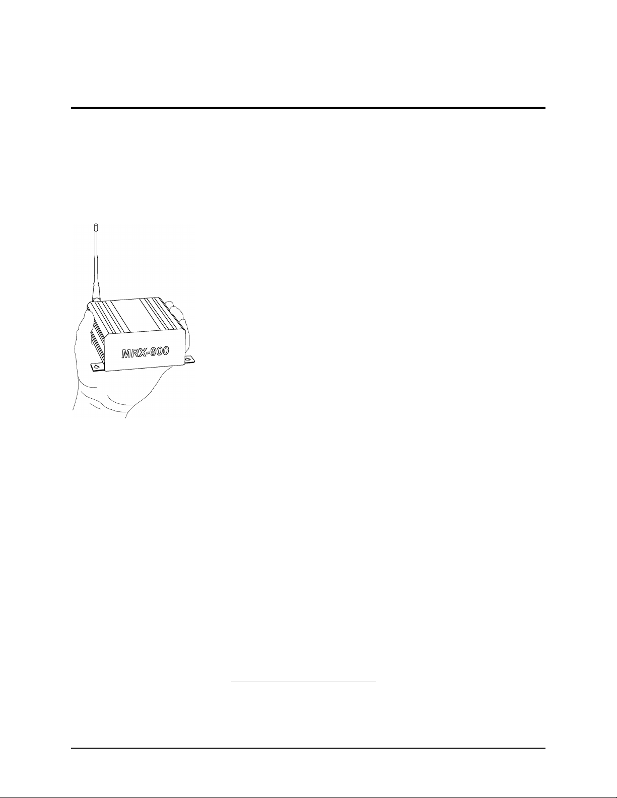
Congratulations on choosing the MRX-900 wireless modem! Your new
MRX-900 is a state-of-the-art, 900 MHz frequency-hopping spread-spectrum
communications transceiver. Equipped with the MRX-900, terminal devices
(DTEs) up to 30 km (or more)1 apart will be capable of establishing highspeed2 communications wirelessly.
Once properly installed and configured, a pair of MRX-900s provides a
practical and reliable alternative to using traditional analog phone-line
modems or “null-modem” serial cable (RS-232) connections for data
communications between terminal equipment. Moreover, wireless data
communications using the MRX-900 means you will benefit from:
n greater flexibility and freedom to relocate terminal equipment,
n reduced cabling hassles,
n eliminated requirement for access to wire-based transfer media
such as telephone lines,
n the ability to communicate through walls, floors, and many
other obstacles.
While the MRX-900 is handsomely sleek and compact in its design, it
delivers power and convenience and offers quality and dependability.
The MRX-900’s versatility makes it the ideal solution for applications
ranging from office-productivity to industrial data control and acquisition.
While a pair of MRX-900 modems can link two terminal devices (“point-topoint” operation), multiple MRX-900 units can be used together to create a
network of various topologies (“point-to-multipoint” operation). Multiple
independent networks can operate concurrently, so it is possible for unrelated
communications operations to take place in the same or a nearby area without
sacrificing privacy, functionality, or reliability.
1.1 Features
Key features of the MRX-900 include:
n transmission within a public, license-exempt band of the radio
spectrum3 – this means there are no conditions on usage of the
MRX-900, and that it can be used without restrictions or access
fees (such as those incurred by cellular airtime);
n a fully compliant RS-232 serial I/O data port with handshaking
and hardware flow control, allowing the MRX-900 to interface
with virtually any terminal device with an asynchronous RS-232
port, such as a computer;
1
Ideal conditions with clear line-of-sight communications, using high-gain antennas.
2
Up to 115,200 bits per second (bps).
3
902-928 MHz, which is license-free within North America; may need to be factory-configured
differently for some countries.
MRX-900 Operating Manual: Introduction. 1

n twenty different user-selectable pseudo-random hopping
patterns to offer the possibility of separately operating multiple
networks while providing security, reliability and high tolerance
to interference;
n encryption key with 65536 user-selectable values to maximize
security and privacy of communications;
n built-in CRC-16 error detection and auto re-transmit to provide
100% accuracy and reliability of data;
n ease of installation and use – the MRX-900 can be used as a
drop-in replacement for most null-modem cable (DTE-to-DTE)
operations, and as a modem replacement with minimal or no
software changes.
While the typical application for the MRX-900 is to provide a mid- to longrange wireless communications link between DTEs, it can be adapted to
almost any situation where an RS-232 asynchronous serial interface is used
and data intercommunication is required.
1.2 About this Manual
This manual has been provided as a guide and reference for installing and
using MRX-900 wireless modems. The manual contains instructions,
suggestions, and information which will help you set up and achieve optimal
performance from your equipment using the MRX-900.
Although the manual is intended for all MRX-900 users from the novice to
the professional, it is recommended that new users of the MRX-900
thoroughly read Chapters 2 and 3, which describe the initial setup and
configuration of the modems. Also, it may be noteworthy to review sections
of Chapter 4 which are relevant to your application while providing helpful
hints for optimizing your MRX-900 modems. The Appendices, including the
Glossary of Terms, are provided as informational references which you may
find useful throughout the use of this manual as well as during the operation
of the wireless modem.
Throughout the manual, you will encounter not only illustrations that further
elaborate on the accompanying text, but also several symbols which you
should be attentive to:
Caution or Warning: Usually advises against some action which could
result in undesired or detrimental consequences.
Point to Remember: Highlights a key feature, point, or step which is worth
noting, Keeping these in mind will make using the MRX-900 more useful
or easier to use.
Tip: An idea or suggestion is provided to improve efficiency or to make
something more useful.
With that in mind, enjoy extending the boundaries of your communications
with the MRX-900, and please remember to send in your warranty
registration!
2 MRX-900 Operating Manual: Introduction
2. Initial Setup and Configuration
2.0 Unpacking and Inspection
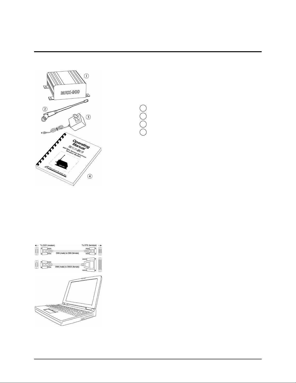
The following items should be found in the shipping carton. Inspect the
modem and accessories for damage. Report damages or shortages to the
distributor from which the unit was purchased. Keep all packing materials in
the event that transportation is required in the future.
Package contents (normal distribution):
1 MRX-900 Wireless Modem 1
2 6” Rubber Ducky Antenna 1
3 9 VDC, 1 Amp Power Adapter 1
4 Operating Manual (this document) 1
The materials you received may vary from those depicted in the figures,
which should be referred to only as a guideline.
2.1 Additional Requirements
Since the MRX-900 is a unique product in a class of its own, it will
communicate only with another MRX-900 which has been compatibly
configured. Thus, at least two MRX-900s will be required to establish a
wireless communications link. Each MRX-900 will also require access to a
120 VAC power source.
Additionally, the following requirements should be taken into consideration
when preparing to install your MRX-900 wireless modem. These represent
“typical” requirements, but due to the large variation of user needs and
applications, the items are user-supplied and are not accessories which
normally ship with the MRX-900. However, most of these are readily
available from any electronics or computer retailer, or they can be ordered
through your distributor for Microhard Systems’ products.
n Shielded “straight-through” RS-232 cable (typically DB9P-to-
DB9S or DB9P-to-DB25S) for each MRX-900 to DTE
connection*.
n Connection adapters and converters, if necessary (e.g., gender-
changers, DB9-to-DB25 adapters, etc.)
n Terminal device (e.g., PC or laptop) with functional RS-232 port
and appropriate communications (terminal emulation) software.
n Mounting hardware (screws) if surface or wall mounting is
desired (see Appendix D for mounting information)
* Note: DB9P denotes a 9-position D-sub male connector (with pins), while DB9S
denotes the mating connector of female gender (with sockets).
Although the physical space required for the MRX-900 is minimal, you
should ensure that there is sufficient room for access to the unit’s rear panel
(where connectors and indicators are located), as well as for an antenna to be
connected (typically oriented in an upright/vertical position).
MRX-900 Operating Manual: Initial Setup and Configuration. 3

2.2 Connectors and Indicators
Locate the rear panel of the MRX-900. The interface connectors and
indicator lights are summarized below. This manual will refer to these items
in the sections that follow.
9 VDC Input - It is recommended that the provided power adapter be used to
supply power to the MRX-900 via this connector, although any
compatible DC power source which has an output of 9 volts and at least 1
amp may be used.
Receive Signal Strength Indicator (RSSI) LEDs - These LEDs show the
quality/strength of the received signal. As the signal strength increases,
the LEDs will illuminate incrementally from bottom to top.
RS-232 Data Port (DCE) - The socketed (female) D-sub connector is used to
interface the MRX-900 to a DTE device and operates at 2400 to 115,200
bps. The same port is used to configure the modem by interfacing to a
terminal (at 9600 bps). See Appendix C for details on the RS-232
interface and line signals.
Configuration Button - This button is used to configure the modem. When
depressed for about 2-3 seconds, the configuration menu will be initiated
and displayed on the connected terminal (DTE) screen. Subsequent
interaction with the modem is performed using the terminal keyboard.
Receive LED - Lights up when the modem receives data over the wireless link,
as well as during internal carrier search and synchronization operations.
Transmit LED - Lights to indicate that the modem is transmitting data wire-
lessly. This light flashes during initial startup and carrier synchronization.
Antenna Connector - Reverse-polarity TNC connector for connecting any
compatible antenna, including the provided rubber-ducky antenna.
Caution: Using any other power
supply which does not provide the
proper voltage or current could
damage the MRX-900 and void
your warranty. Doing so is at your
own risk.
2.3 Hardware Setup
Prior to setting up and configuring the MRX-900, please observe the
requirements outlined in Section 2.1. When you are ready for the initial
setup:
1. Connect the modem to a terminal or personal computer (DTE) using a
standard serial cable. Depending on the connector on your DTE device, you
will typically need a DB9-to-DB9 or DB9-to-DB25 cable (see Appendix C
for additional information). Connect the male DB9 end of the cable to the
MRX-900 data port.
2. Apply power to the MRX-900 by plugging the provided adapter into the
power input socket, and the other end into an active 120 VAC outlet. (You
will see the Receive LED illuminate to indicate that it is operating normally.)
3. On your terminal or in your terminal program (e.g. HyperTerminal in
Microsoft Windows or Procomm Plus from Datastorm Technologies), ensure
that the correct port is selected and that it has been configured for a speed of
9600 baud and a data format of 8N1 (8 bits, No parity, 1 stop bit). Although
no terminal emulation is necessary, TTY can be selected if desired.
4. You are now ready to configure the modem for operation. The following
sections will walk you through the procedure.
4 MRX-900 Operating Manual: Initial Setup and Configuration
2.4 Configuration
Prior to establishing a wireless link, each MRX-900 that will participate in
the link must be correctly configured for compatibility and for the desired
mode of operation.
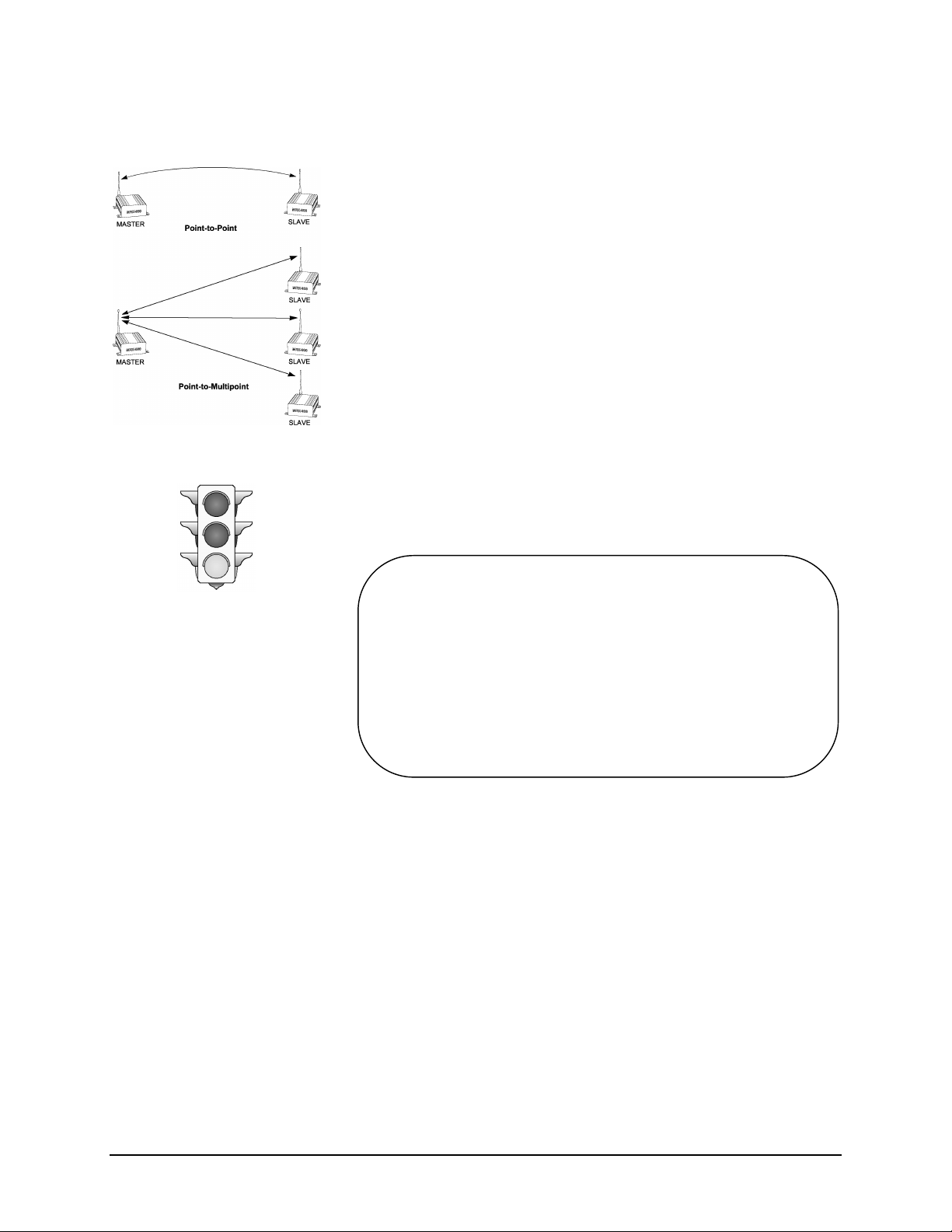
The two most common types of networks used are:
n Point-to-point: A master station communicates with a single
slave station.
n Point-to-multipoint: A master station communications with
two or more slave stations.
Within any network, the master will communicate only with slave(s) assigned
to the same network. Similarly, a slave will only communicate with the
master of the network to which it is assigned.
The quick configuration procedure is outlined below for each of these modes.
2.4.1 Quick Start Approach
Assuming your hardware has been properly setup (as outlined in Section 2.3)
for configuration, you are now ready to begin the process. Start by locating
the Configuration Button at the rear of your MRX-900 and pressing it for two
to three seconds. A menu similar to the following should appear on your
terminal screen:
Microhard Systems Inc
MRX-900 Configuration
1) Operating Mode Slave - Point to Point
2) Serial Baud Rate 115200
3) Wireless Link Rate Turbo
4) Network Address 1
5) Unit Address 1
6) Hopping Pattern A
7) Encryption Key 0
8) Output Power Level 1 mW
9) Packet Parameters
A) Radio Stats
ESC to exit
Select an Item to Configure : _
The minimum configuration requirements for point-to-point and point-tomultipoint are summarized below. These requirements will get you started
and only ensure that a link can be established, but do not necessarily provide
the best performance; optimization of the communications link is discussed
in later sections.
A. Point-to-Point
To establish a point-to-point communications link, the following requisites
must be satisfied:
n The Operating Mode for one modem must be configured as a
“Master - Point-to-Point”, and the other as a “ Slave - Point-to-
Point”.
n The Serial Baud Rate for each modem must be set to match the
baud rate of the connected equipment (DCE and DTE rates must be
equivalent).
MRX-900 Operating Manual: Initial Setup and Configuration. 5

n The Wireless Link Rate for both modems must be the same.
n The Network Address assigned for both modems must be the
same.
n The Unit Address assigned for both modems must be the same.
n The same Hopping Pattern must be selected for both modems.
n Both modems must use the same Encryption Key.
B. Point-to-Multipoint
To establish a point-to-multipoint network, the following requisites must be
satisfied:
n The Operating Mode for one modem must be configured as a
Point-to-Multipoint Master, and the others as Point-toMultipoint Slaves.
n The Serial Baud Rate for each modem must be set to match the
baud rate of the connected equipment (DCE and DTE rates must be
equivalent).
n The Wireless Link Rate for all modems must be the same.
n The Network Address assigned to all modems must be the same.
n Each Slave must be assigned a unique Unit Address.
n The Master must have a list of all Slave Unit Numbers in its Slave
List.
n The same Hopping Pattern must be selected for all modems.
n All modems must use the same Encryption Key.
Warning: Using an antenna other
than one approved by Microhard
Systems Inc. could result in
undesired performance, and may
damage the MRX-900. Failure to
use an approved antenna may void
your warranty. It is the user’s
responsibility to ensure the
antenna has adequate lightning
protection.
Each of the parameters above are defined using the terminal to display the
menu-driven configuration screens and setting the appropriate items. Settings
are immediately stored in non-volatile memory upon selection, and are
therefore retained even after powering down. Each item and the settable
parameters within the modem configuration are described in detail in Chapter
3: Configuration Options. Once the configuration is complete, the modems
can be restored to operation mode by either pressing ESC to exit the menu
(“Running ...” should then appear), or simply by power-cycling the unit
(momentarily disrupting power to the unit, then restoring it).
2.5 Checking the Link
Once configured properly, a pair or set of communicating modems can be tested
to ensure that a link can be successfully established. Attach the provided antenna
to the antenna connector on each MRX-900 and screw the antenna in snugly.
The modems should indicate the status of the wireless link via the RSSI
LEDs on the rear panel: if the link is good, up to three LEDs should
illuminate; and if the link is absent (due to a fault at one end or another, such
as misconfiguration), the LEDs will be unlit. It is recommended that if
MRX-900s will be deployed in a field where large distances separate DTEs,
the modems be configured and tested in close proximity (e.g., in the same
room) first to ensure a good link can be established and settings are correct.
This will facilitate troubleshooting, should problems arise.
6 MRX-900 Operating Manual: Initial Setup and Configuration
3. Configuration Options
3.0 Configuration Parameters
The MRX-900 is easily configured to meet a wide range of needs and
applications. Configuration is fully menu-driven and requires only a terminal
with a 9600 baud RS-232 port. Configuration mode is initiated by depressing
the Configuration Button on the back panel of the MRX-900 and holding it
for at least two or three seconds. The main configuration menu is then
displayed:
Microhard Systems Inc
MRX-900 Configuration
1) Operating Mode Slave - Point to Point
2) Serial Baud Rate 115200
3) Wireless Link Rate Turbo
4) Network Address 1
5) Unit Address 1
6) Hopping Pattern A
7) Encryption Key 0
8) Output Power Level 1 mW
9) Packet Parameters
A) Radio Stats
ESC to exit
Select an Item to Configure : _
In configuration mode, the
default serial rate for the
MRX-900 is 9600 baud.
Refer to Appendix A (page
15) for a menu navigation
chart to facilitate use of the
configuration menus.
Configuration options are
immediately stored in nonvolatile memory when
selected and become active
after exiting configuration or
power-cycling the unit.
Note that 9600 baud is the default rate for configuration only, and that the
actual data communications rate during operation is user-defined, with rates
from 2400 to 115,200 bps. (With reference to the serial data port, baud and
bps can correctly be used interchangeably since no modulation occurs to
increase the bit rate over the baud rate. This may not always be the case with
modulated signals transmitted between DCEs.) No terminal emulation is
required, although a “TTY” setting can be used if mode selection is required
by your communications software.
Most menu items are hot-key driven, requiring minimal keypresses to quickly
navigate and set parameters. Current parameters are indicated to the right of
each item in the main configuration menu (see above), and preceded by an
asterisk (*) for each chosen option in parameter submenus (shown on
following pages). Configuration parameters are saved in non-volatile
memory as soon as they are selected. This allows quick configuration of the
modem and reactivation in operation mode by either pressing ESC on the
terminal from the main configuration menu, or simply power-cycling the unit
(momentarily disconnecting power to the MRX-900).
3.1 Operating Mode
The Operating Mode partly defines the “personality” of the MRX-900.
When item 1 is chosen from the configuration menu, the following options
are available:
MRX-900 Operating Manual: Configuration Options 7
 Loading...