

Page 1

Page 2

TABLE O
F
U
N
A
M
A
A
I
E
D
o
o
a
O
n
b
O
e
h
n
Y
o
e
L
N
S
L
N
A
D
o
e
o
h
/
7
p
O
o
l
s
e
I
G
v
e
p
u
e
n
s
u
a
e
c
h
n
u
e
x
n
d
y
o
n
g
i
b
o
c
a
t
m
u
a
m
t
c
e
m
e
e
n
r
i
p
M
r
s
s
u
n
l
u
m
1. INTROD
2. SAFTEY
3. OPERAT
4. MOUNTI
5. DMX-512
6. MENU N
7. PHOTO
8. DMX CH
9. KEY FE
10. TECHN
11. MAINT
1. INTRO
Thank you f
manual bef
Please inst
The MICR
designed a
applicable
CONTENTS
CTION AND U
INSTRUCTION
ION INSTRUCT
G AND INSTA
CONTROL CO
VIGATION
ETRIC DATA
NNELS
TURES
CAL SPECIFIC
NANCE AND C
UCTION AN
r purchasing th
re installing or
ll and operate t
H LED SLIM P7
d manufactured
ut not limited to
ONS
LEANING
UNPACKIN
perating the de
e fixture accordi
P12 wash fixtur
strictly following
large-scale live
PACKING
LATION
NECTIONS
TIONS
MICROH LED
SLIM P7/P12 w
ice. This manua
ng to instruction
is made of a n
CE standards,
erformances, t
sh fixture. For
l covers the imp
s. Meanwhile, pl
w type of high t
omplying with i
eater, studio, ni
1
1-2
2-4
5
6
6-7
8
8-10
10-11
11
12
our own safety
rtant informatio
ease keep this
emperature cas
ternational stan
htclubs and dis
nd knowledge,
n on installation
anual for futur
aluminum casi
dard DMX512 p
os.
please read this
and application
reference.
g. The fixture is
otocol. This fixt
.
re is
The MICR
stability. Pl
check whet
Fixture – O
2. SAFTE
This device
necessary f
If the devic
the device.
H SLIM PAR P
ase carefully un
er the following
e
INSTRUCTI
has left the fact
r the user to fol
has been expo
eave the devic
/P12 LED wash
ack it when yo
items are includ
Power Cord –
NS
ry in perfect co
ow the safety in
ed to temperat
switched off un
fixture uses 7 a
receive the fixt
d inside the bo
One
dition. In order t
tructions and w
re changes, do
til it has reache
d 12 powerful T
re and check if
:
XLR Signal Ca
maintain this
rning notes wri
ot switch it on i
room temperat
RI (3in1) LED’s,
it was damaged
le – One
ondition and to
ten in this user
mediately. Th
re, and is dry.
which feature h
during the trans
User
nsure safe ope
anual.
arising conden
gh brightness a
portation. And p
anual – One
ation, it is absol
ation could da
d
ease
tely
age
1
Page 3
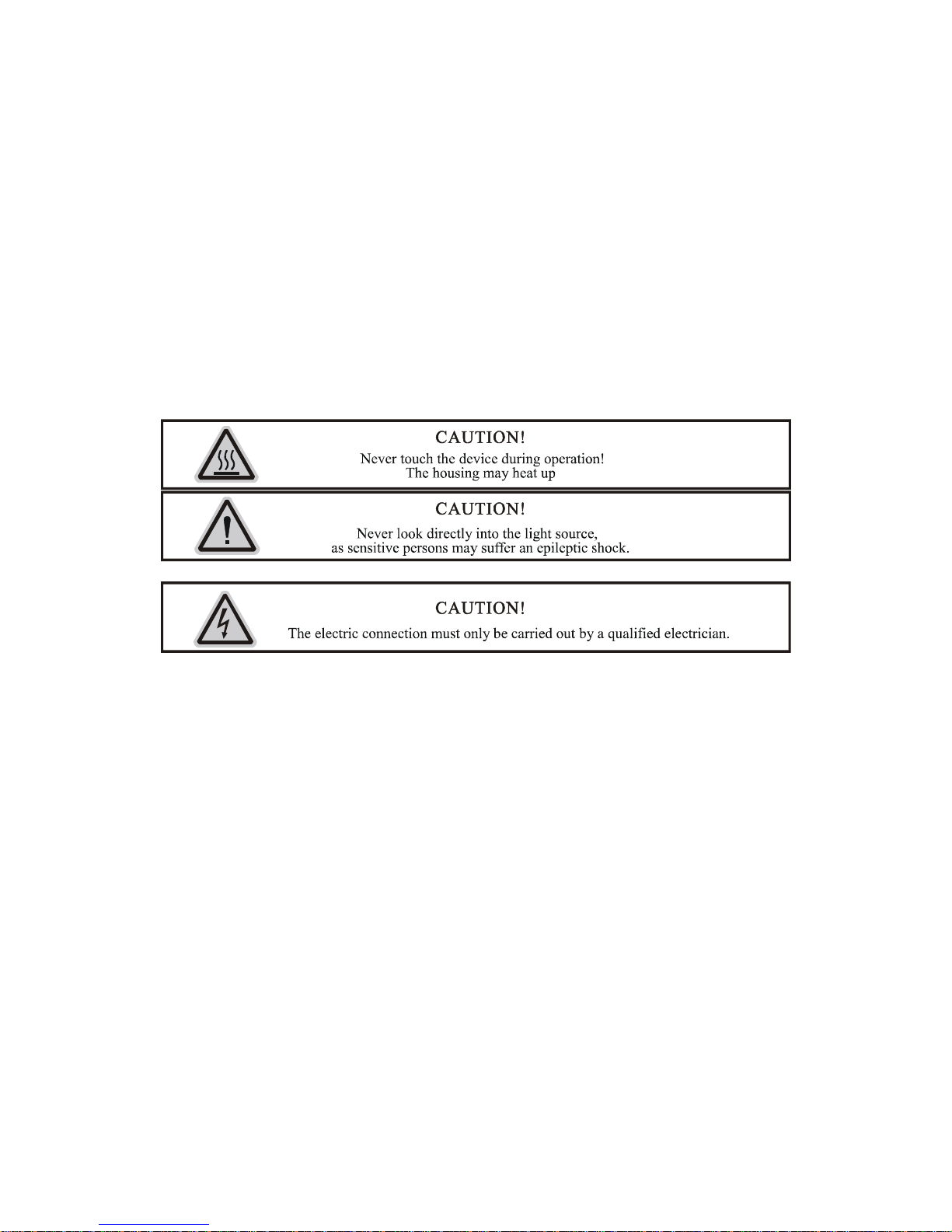
This device falls under protection-class I, therefore it is essential that the device be grounded. The electrical connection must be
carried out by a qualified technician.
The device should only be used with rate voltage and frequency. Make sure that the available voltage is not higher than 120V as
stated at the end of this manual.
Make sure the power cord is never crimped or damaged in any way, as this could cause shock and damage. If your power chord is
damaged in any way, please purchase a new cable from your local MICROH dealer. Always disconnect power, when the device is
not in use or before cleaning it. Never pull out the plug by tugging the power cord.
During initial start-up, some smoke or smell may arise. This is a normal process, and does not necessarily mean that the device is
defective. It should decrease gradually. Please do not project the beam onto combustible substances.
Fixtures cannot be installed on or near combustible substances. Keep more than 50cm distance from wall for proper ventilation and
air flow. If your fixture is or has become damaged in any way, it shall be exclusively replaced or repaired by the manufacturer to
avoid any hazard.
3. OPERATION INSTRUCTIONS
- Do not turn on the fixture if it has been through severe temperature differences. Damage may occur to the fixture. Wait
until unit is at room temperature to operate.
- The unit should be protected from any tremor or agitation during transport.
- Do not expose the fixture in any excessive heat, moisture or any environment with too much dust when installing. Do not
lay any power cables on the floor. It may cause electronic shock or damage to persons or equipment.
- Make sure to attach the safety chain and ensure the screws are properly screwed in when installing the fixture.
- Make sure the lens is in good condition. It is recommended to replace the unit if there are any damages or severe
scratches.
- Make sure the fixture is operated and installed by qualified personnel.
- Keep the original packaging in case of defective product.
- Any non-manufacturer additions, modifications or changes in any way will void all warranty.
- Please do not attempt to open unit. It is only to be serviced by an authorized technician. If this occurs, or is apparent, the
warranty will be voided.
2
Page 4
-
Top
Bto- O- A
)Pr
)Pr
OPrch1)2)Pr
U
r
)
r2)
r
)
rsp
r
s
f
m
e
o
0
d
M
o
e
U
d
c
t
c
G
o
o
t
t
a
t
i
d
c
X
1
O
a
s
,
l
e
e
s
c
p
a
m
r
O
m
s
~
y
a
e
n
e
a
e
e
s
y
s
e
e
n
e
h
o
l
a
s
N
N
t
u
h
e
a
r
e
r
u
P
c
c
d
s
~
t
o
n
he fixture’s wa
eration (shock
M
ASTER/SLAVE
ranty will be voi
hort circuit, ele
MODE
ed if there are
tronic shock, la
ny malfunctions
p broke, etc.)
from not followi
g the user man
al or any illegal
-
y connecting th
gether by pluggi
n your Master
ll slave lights
M
ANUAL DIMME
1
Manual dimm
ess MODE butt
~
e dimming rate
th
Flash speed s
2
ess SET UP an
". (00-1
UND ACTIVE
S
ess MODE butt
oose.
Sound activ
Press SET
program mo
e 3 pin DMX, yo
ng from the DM
ixture set the un
ust be set “A00
R COLOUR M
r colour select
n, select the m
", Green "
-255.
elect
choose the fla
5, 00 is flash off
ODE
n, select the so
program mode
P button and se
e (1-8).
u can daisy chai
output of the fi
it to either AUT
”
DE
nual dimmer co
~
h speed select
01 is the slowe
und active progr
select
ect “
n up to 30 units
st fixture into th
or SOUND co
lour select mod
", blue"
ode. Press UP
t flash speed, 1
m mode. Ther
", th
on master/ slav
DMX input of t
trol and select
. Press SET UP
~
or DOWN to se
5 is the fastest f
are two sound
n press UP or D
mode. Daisy c
e second fixtur
ne of the intern
to choose diffe
"). Press UP o
lect the flash sp
ash speed.)
ctive modes, p
OWN to select t
ain the fixtures
, and so on…
l programs.
ent colours (Re
r DOWN button
ed “
ess SET UP to
he sound active
“
to set
Sensitivity sele
ess SET UP bu
(1
-8. 1 is sound-a
TO RUN PRO
A
P
ess MODE butt
1
Colour fade pr
P
ess SET UP bu
Colour change
P
ess SET UP bu
(1
-8.)
Colour fade/ch
3
P
ess SET UP bu
eed (01-16, 01
t mode
ton and select "
tive off, 2 is the
RAM MODE
n and select th
gram mode sel
ton and select “
program mode
ton and select “
nge speed sele
ton and select “
s the slowest s
~
lowest sensitivit
auto-run progr
ct
~
elect
~
t
~
eed, 16 is the fa
" then pre
, 8 is the highe
m mode. There
", then pr
", then pr
". Press U
stest speed.)
s UP or DOWN
t sensitivity.)
are three mode
ss UP or DOW
ss UP or DOW
P or DOWN but
to select the so
, press SET U
button to sele
button to sele
on to select the
nd active sensi
to choose.
t fade program (
t the change pr
colour fade/cha
ivity
1-8.)
gram
ge
3
Page 5
S
TPr1)Pr
)Pr(0
o1)Thbuat
i2)Pr
)
r
)
ran3)
rre
R
o
e
t
e
e
t
h
s
“
h
C
t
T
E
s
t
e
l
t
d
o
a
s
M
e
d
o
t
d
h
e
w
d
X
d
e
s
d
o
a
n
e
s
r
e
=
U
s
d
N
s
w
u
T
e
s
N
t
r
X
c
a
o
n
s
P
t
e
c
o
e
U
n
p
a
d
e
s
o
d
O
ATIC COLO U
SELECT MOD
E
ess MODE butt
Static colour s
ess SET UP bu
1
= Red, 2 = Gre
Flash speed s
2
ess SET UP bu
0-15, 00 is flash
X MODE
D
Y
u can control t
DMX address
e control board
tton and select
most when it is
ost when it is in
m
ll flicker when t
w
DMX-PROTO
n, and select th
lect
ton and select “
n, 3 = Blue, 4 =
lect
ton select “
off, 01 is the sl
e units individu
elect mode
allows you to a
~
in 3 channel D
5 channel DMX
ere is no control
OL
e static colour s
~
Cyan, 5 = Yello
~
west flash spee
lly via your DM
sign the DMX a
”, then pr
X mode, 509pc
mode, 507pcs a
ler signal.
lect mode. The
", then pr
, 6 = Purple, 7
", then press
,15 is the faste
-controller.
dress which is
ss UP or DOW
address at mo
dress at most
e are two mode
ss UP or DOW
White)
P or DOWN but
t flash speed.)
efined as the fi
N to set the DM
t when it is in 4
hen it is in 6 ch
, press SET U
to select static
ton to select sta
st channel of th
address. You
channel DMX m
nnel DMX mod
to choose.
colour (0-7. 0 =
ic colour flash s
unit. Press MO
an set 510pcs
de, 508pcs ad
. The digital di
Black,
eed
DE
ddress
ress at
play
ess SET UP bu
th
e desired chann
HER FEATUR
O
1
Display off/on
P
ess SET UP bu
"
2
Display norma
P
ess SET UP bu
d select “
Initialization sel
P
ess SET UP an
set the unit to th
". Sel
ton and select “
els (3,4,5,6).Th
S
elect mode
ton, and select
ct " "t
/inversion selec
ton, and select
". To have t
ect mode
select "
e factory default
” “
re are four total
isplay off/on m
have the unit
mode
isplay normal/i
e display invert
", and the di
settings.
” “
DMX modes.
de. To have the
utomatically sh
version mode.
d select "
play flickers. Pr
” or “
display continu
t off display afte
o have the displ
".
ss UP button a
”, then press
usly on press
r 60 seconds of
ay set to normal
d DOWN butto
UP or DOWN t
P or DOWN an
inactivity.
, press UP or D
s simultaneousl
set
select
WN
y to
4
Page 6

4. MOUN
T
o
o
a
s
P
m
o
c
n
u
u
a
b
e
T
m
t
o
m
t
d
s
n
b
R
g
p
r
x
o
s
o
i
c
o
d
m
l
n
r
v
x
o
a
e
n
s
t
d
a
(
a
a
o
n
r
t
t
s
o
e
e
r
e
b
a
w
t
n
P
t
e
a
w
r
a
w
a
d
v
t
t
r
a
r
r
r
s
e
m
o
c
p
h
e
u
Caution: F
be reached
minimum p
such as an
ING AND INS
r added protecti
by unauthorized
int load of 10 ti
ppropriate safe
ALLATION
on, mount the fi
personnel. Bef
es the device’s
y cable. Never
tures in areas o
re mounting the
weight. Fixture i
tand directly bel
utside walking p
fixture to any su
stallation must
ow the device w
aths, seating ar
rface, make sur
always be secu
hen mounting, r
as, or in areas
that the install
ed with a secon
moving, or ser
ere the fixture
tion area can h
ary safety atta
icing the fixture.
ight
ld a
hment,
Whether in
least 0.5m (
measure to
Mounting
installation
only be perf
Be sure to
Floor Mou
Clamp Mo
used to mo
included br
cable to the
talling inverted
1.5 ft) away fro
prevent acciden
oints: Overhea
aterial being u
rmed by a qual
omplete all riggi
ting: Set the 2
nting: The MIC
nt on a truss or
cket fitted throu
fixture.
n a truss or ceili
any flammable
al damage and/
mounting requ
ed, and periodi
fied technician.
g and installati
rackets at your
OH LED SLIM
the floor. When
h the center ho
ng, or set on a fl
materials (deco
r injury in the e
res extensive e
safety inspecti
Improper install
n procedures b
esired angle a
P7/P12 provide
ounting this fix
e. As an added
at level surface
ation etc.). Alw
ent the clamp f
perience, includ
n of all installati
tion can result i
fore connecting
d aim your fixtu
a unique moun
ure to truss, be
afety measure,
see illustration
ys use and inst
ils.
ing calculating
n material and
bodily injury a
the main power
e accordingly.
ing bracket ass
sure to secure
be sure to attac
elow). Be sure
ll the supplied s
orking load limi
he fixture are al
d damage.
cord to the app
lease see diagr
mbly that integ
n appropriately
h at least one p
his fixture is ke
afety cable as a
s. A knowledge
l imperative and
opriate wall outl
m below.
ates 2 brackets
ated clamp to t
operly rated saf
t at
safety
of the
should
et.
to be
e
ty
Regardless
a safety ca
only use th
of the rigging o
le. The fixture p
designated rigg
tion you choose
ovides a built-in
ing point for the
for your MICRO
rigging point for
safety cable an
H SLIM P7/P12
a safety cable
never secure a
wash fixture, al
n the hanging b
safety cable to
ays be sure to
acket as illustra
carrying handl
ecure your fixtu
ted above. Be s
.
re with
re to
5
Page 7
5. DMX-51
c
d
E
a
i
t
L
n
N
A
C
t
e
X
D
2
a
n
A
N
T
3
o
i
n
o
P
0
o
r
a
n
s
e
e
h
e
o
h
M
c
c
c
c
i
3
s
t
t
g
u
r
e
M
t
r
p
a
d
o
2 CONTROL
ONNECTIO
S
This fixture
the provide
MICROH L
below. Alw
For installat
use a DMX
simply an X
last fixture i
omplies with in
3 pin XLR cabl
D SLIM P7/P12
ys end your DM
ons where the
erminator. This
R plug with a 1
the chain. Ple
ernational USIT
to the female
. To connect the
-512 connectio
MX cable has t
helps in prevent
0 Ω resistor co
se see illustrati
DMX standard
-pin XLR output
units to DMX, y
n with a DMX te
run a long dist
ng corruption of
nected betwee
ns below.
and can be us
of your controll
u must daisy c
minator.
nce, or is in an
the digital contr
pins 2 and 3,w
d with either a
r and the other
ain the fixtures
lectrically noisy
l signal by elec
ich is then plug
pin or 5 pin D
ide to the male
ogether as refe
environment, it
rical noise. The
ed into the out
X connector. Pl
3-pin XLR input
red in the diagr
is recommende
DMX terminator
ut XLR socket
ug in
of the
m
to
is
f the
6. MENU
MODE
Manual
DMX MODE
AVIGATION
SET UP Ma
ddress
Channels
12
ual U
2
1
/DOWN Manual
~
3
Sets the D
The unit o
The unit o
The unit o
The unit o
PIN
PIN
Instr
X starting add
cupies 3 DMX c
cupies 4 DMX c
cupies 5 DMX c
cupies 6 DMX c
3
2
ction
ess
hannels
hannels
hannels
hannels
Red dimmer
~
Adjust the
ntensity of the r
d colour
6
Page 8
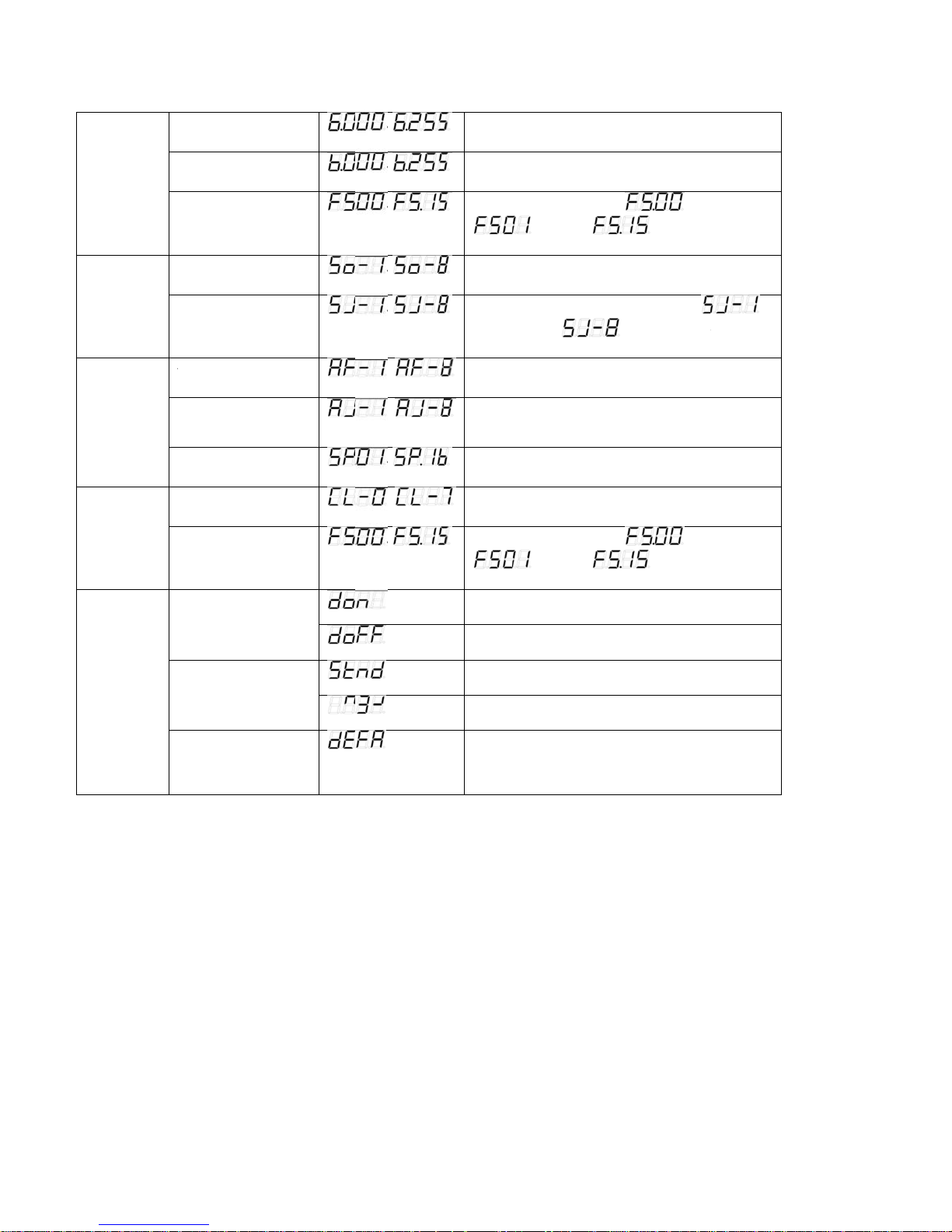
D
M S
M ARMSCSM
O
M
A
t
A
o
P
s
o
i
i
e
b
l
b
b
s
e
e
e
b
o
e
m
D
u
w
r
v
a
v
d
v
IMMER
ODE
Green dimmer
Blue dimmer
~
~
Adjust the
Adjust the
ntensity of the g
ntensity of the
reen colour
lue colour
OUND
ODE
UTO
UN
ODE
TATIC
OLOUR
ELECT
ODE
THER
ODE
Flash
Mode select
Sensitivity selec
UTO FADE m
COLOUR JUM
et
Speed set
Colour select
Flash
Display
n/off
Display
normal/inverse
de set
mode
~
~
~
~
~
~
~
~
Adjust th
Select the
Adjust the
the lowest
Select the
Select the
Adjust the
Select the
Adjust th
LED digital
LED digital
LED digital
LED digital
flash speed
is slowest,
uilt-in sound m
sensitivity of th
level,
uilt-in FADING
uilt-in jumping
peed of the FA
ight static colo
flash speed
is slowest,
tube display al
tube display off
tube display no
tube display in
, is
is fastest
de
sound-active,
is the highest le
mode
ode
E/jumping mo
rs
, is
is fastest
ays on
mal
ersion
flash off,
is
el
e
flash off,
Initialization
Initialize th
unit at the extr
a factory setting
mode
7
Page 9
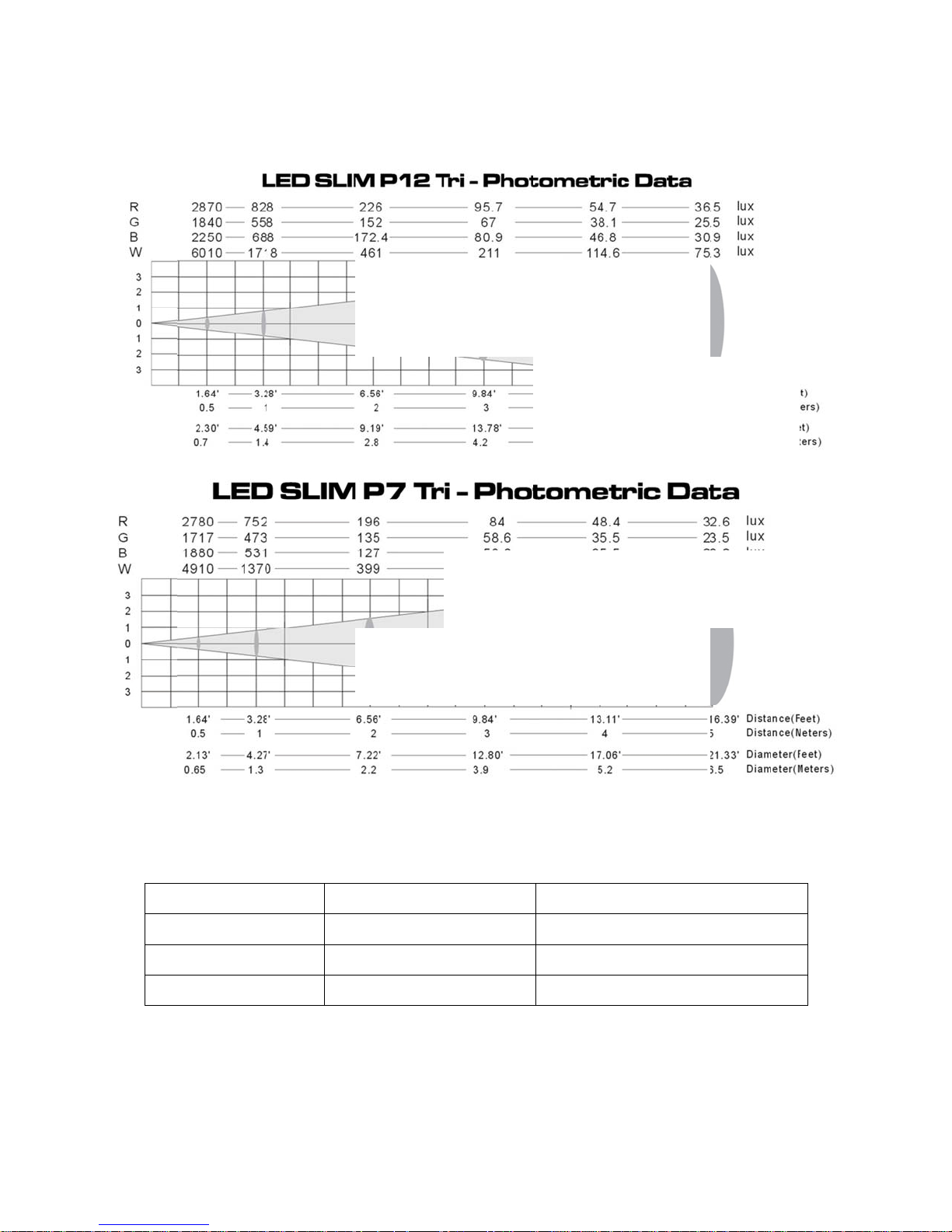
7. PHOTO
H
n
A
l
5
5
5
G
h
METRIC DAT
8.
DMX C
ANNELS
① set 3 cha
nels
CH No.
CH1
CH2
CH3
DMX va
000~2
000~2
000~2
ue
5
5
5
Function
Red(dim→brigh
reen(dim→brig
Blue(dim→brig
t)
ht)
t)
8
Page 10
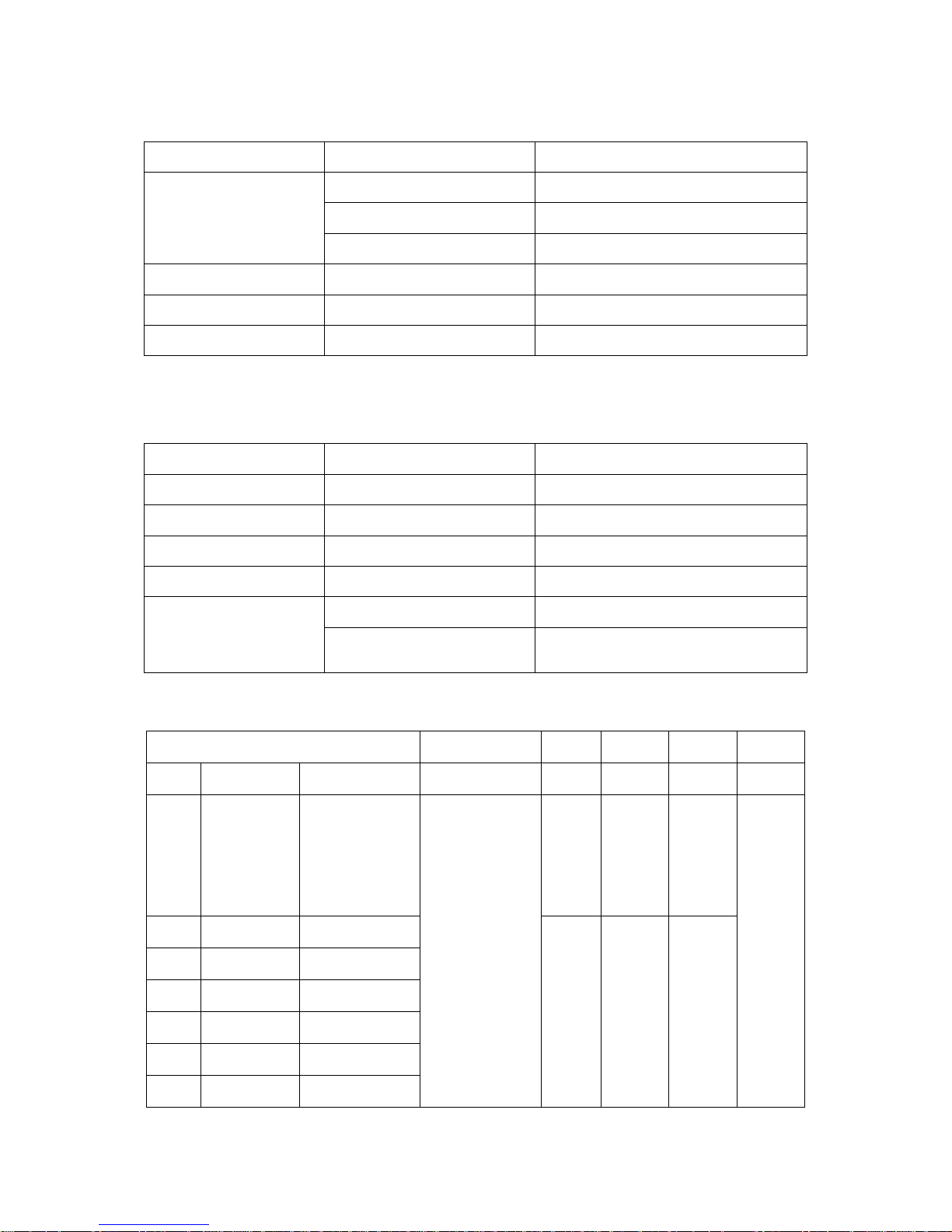
② set 4 channels
③ set 5 channels
CH No. DMX value Function
CH1 000~189 Dimming(dim→bright)
190~250 Strobe(slow→fast)
251~255 No function
CH2 000~255 Red(dim→bright)
CH3 000~255 Green(dim→bright)
CH4 000~255 Blue(dim→bright)
CH No. DMX value Function
CH1 000~255 Red(dim→bright)
CH2 000~255 Green(dim→bright)
CH3 000~255 Blue(dim→bright)
CH4 000~255 Dimming(dim→bright)
CH5
④ set 6 channels
CH6 CH5 CH4 CH3 CH2 CH1
MODE DMX VALUE FUNCTION
1 0-15 No function
2 16-31 Red
3 32-47 Green
4 48-63 Blue
5 64-79 Cyan
6 80-95 Yellow
7 96-111 Purple
000~015 No function
016~255
Strobe slowest to
fastest
16-255
flash frequency is
0.1HZ-20HZ
0-255
(dim→
bright)
Strobe slowest to fastest
flash frequency is 0.1HZ-20HZ
Blue
Green
0-255
(dim→
bright)
Red
0-255
(dim→
bright)
Dimming
0-255
(dim→
bright)
9
Page 11
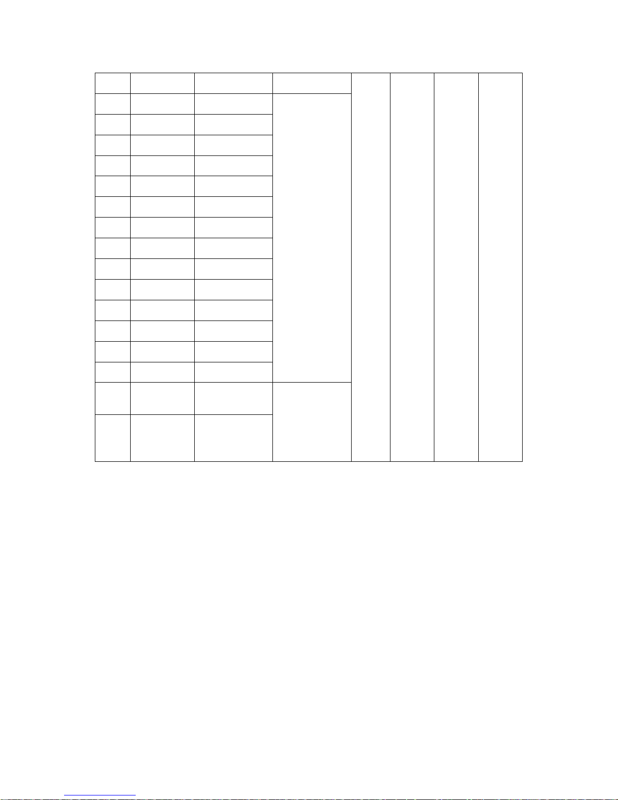
8 112-127 White
9 128-135 Colour fade 1
10 136-143 Colour fade 2
11 144-151 Colour fade 3
12 152-159 Colour fade 4
13 160-167 Colour fade 5
14 168-175 Colour fade 6
Speed 0-255
15 176-183 Colour fade 7
16 184-191 Colour fade 8
17 192-199 Colour change1
18 200-207 Colour change 2
19 208-215 Colour change 3
20 216-223 Colour change 4
21 224-231 Colour change 5
22 232-239 Colour change 6
23 240-247 Sound mode1
(slow→fast)
Sensitivity
0-255
No
function
No
function
No
function
24 248-255 Sound mode2
(insensitive →
sensitive)
9. KEY FEATURES
- The MICROH LED SLIM P7 uses 7, 3W TRI LED’s (3in1)
- The MICROH LED SLIM P12 uses 12, 3W TRI LED’s (3in1)
- 50,000 hours Lifespan and Low Power Consumption
- LED SLIM PAR Series all Have a 40º Projection Beam Angle
- 0 - 100% Linear Dimmer with 1-18 Flashes/sec High Speed Electronic Strobe
- 3, 4, 5, or 6 DMX channels (4 DMX modes)
- Macros, Auto Fade, Chases
- Master/Slave, Auto, DMX, Sound Active, Colour Fade, Colour Chase & Static Colour.
- IEC AC Input & Output
- 3 Pin DMX Input & Output
10
Page 12

n
L
N
L
A
V
G
2
3
S
N
E
S
A
D
c
d
F
/
A
”
x
.
m
s
o
x
/
v
P
5
m
a
r
- Built-i
- 4 Butt
Microphone
on Digital LED
isplay
LENS REP
front cover.
10. TECH
MODE
LAMP:
OPER
OLTA
FUSE:
MAX:
DIMEN
PACKI
NET W
GROS
WARR
ACMENT – To
Please refer to
ICAL SPECI
: LED SLIM P7
7 3W Tri LEDs
TING TEMPER
E: AC90-240V
A 250V GMA
0W
IONS: 7” x 3.4
8” x 3”
G DIMENSION
IGHT: 6 lbs / 2
5.95 lbs
WEIGHT: 7.55
NTY: 2 Year Li
hange the lens,
iagram below.
ICATIONS
/ LED Slim P12
12 3W Tri LED
TURE: -25°C t
50-60Hz
x 10.25” / 178
11.5”/ 203 x 76
S: 13.5” x 12” x
72 (P7)
2.70 (P12)
lbs / 3.42 kg
ited Warranty
you must remo
45°C
86 x 260 mm (
x 292 mm(P12)
.13” / 343 x 30
e 3 screws fro
7)
x 181 mm
the front plate, re-fix new lens
nd replace 3 sc
ews to
11
Page 13
11. MAIN
T
w
u
c
r
k
e
e
e
o
m
o
O
i
t
E
s
n
D
h
e
t
y
n
s
c
f
c
E
o
e
r
p
d
s
h
w
o
a
w
t
g
e
v
d
B
a
m
n
c
m
w
m
s
l
e
U
e
u
o
o
o
t
t
m
e
o
o
n
t
o
n
u
n
e
u
O
o
a
d
s
h
a
o
n
O
H
s
e
.
c
h
The followin
ENANCE AN
g points have to
CLEANING
be considered
uring the inspe
tion:
1) All scre
2) There m
3) Mechani
4)The ele
Further inst
issues must
In order to
1) Clean th
2) Clean th
3) A detail
conditi
s for installing t
st not be any d
cally moved par
tric power suppl
uctions dependi
be resolved.
eep the fixture i
inside and out
fan each week
d electrical che
n, and prevent
e device or part
formations on t
s must not sho
cables must n
g on the install
good condition
ide lens each
.
k by approved
rom overheatin
of the device
e housing, colo
any traces of
t show any da
tion spot and u
and extend the
eek to avoid the
echnician every
.
ust be tightly c
ur lenses, fixati
earing and mus
age, material fa
age must be ha
ife, we suggest
light output fro
three months is
nnected, and m
ns or installatio
not rotate with
igue or sedime
ndled by a skille
regular cleaning
darkening due
advised. Ensur
ust not be corro
spots (ceiling,
nbalances.
ts.
d installer or tec
to the fixture.
to accumulation
the circuit cont
ed.
uspension, trus
hnician. Any saf
of dust, dirt, etc
cts are in good
ing).
ty
We recom
There are n
Should you
IF YOU SH
EMAIL AT
In the even
repair.
DISCLAIM
not respon
manual ca
end a frequent
serviceable pa
need any spare
ULD EXPERI
nfo@microhpr
that your unit
R – MICROH b
ible for any er
be improved
leaning of the d
rts inside the de
parts, please or
NCE ANY PRO
.com
is defective in
lieves that the
or or addendu
lease contact i
vice. Please us
ice. Please ref
er genuine MIC
LEMS OR ISS
ny way, pleas
information co
s to this man
fo@microhpr
e a moist, lint- fr
r to the instructi
ROH parts from
ES PLEASE C
contact your l
tained within
al. If you have
.com. Thank y
ee cloth. Never
ns under “Insta
your local deale
ONTACT MICR
cal dealer to
his user manu
any comments
u.
se alcohol or s
llation instructio
r.
H PROFESSI
btain an RA nu
l is accurate.
or general sug
lvents.
s”.
NAL PRODUC
mber for servi
owever, Micro
gestions on ho
TS BY
e
is
w this
12
Page 14

 Loading...