

Page 1

Microgate s.r.l.
Via Stradivari, 4 Stradivaristr.
39100 BOLZANO - BOZEN
ITALY
POLIFEMO
RADIO
USER MANUAL
Release 200_006
Page 2

POLIFEMO-RADIO
User manual
Doc: POL_R_200_006_E
Version: 2.0
Page
2 of 11
1. SUMMARY
1. SUMMARY.................................................................................................................................2
2. INTRODUCTION .......................................................................................................................3
3. POLIFEMO-RADIO....................................................................................................................4
3.1. DIP SWITCH CONFIGURATION.....................................................................................4
4. OPERATING MODES................................................................................................................5
4.1. CENTERING.......................................................................................................................5
5. RADIO TRANSMISSION ..........................................................................................................5
5.1. DIGITAL TRASMISSION OF IMPULSES .......................................................................5
5.2. SELECTING THE CHANNEL...........................................................................................6
5.3. SELECTING SIGNAL TYPE.............................................................................................7
5.4. IMPULSE TRASMISSION.................................................................................................7
5.5. THE RECEIVING DEVICE................................................................................................7
6. THE OUTPUTS...........................................................................................................................9
6.1. OUTPUT SIGNAL ..............................................................................................................9
7. POWER SUPPLY........................................................................................................................9
7.1. RECHARGE MANAGEMENT........................................................................................10
7.1.1. IMMEDIATE RECHARGE......................................................................................10
7.1.2. ANOMALIES............................................................................................................10
8. TECHNICAL DATA.................................................................................................................11
9. LINKGATE_SF DECODER TECHNICAL DATA .................................................................11
Page 3
POLIFEMO-RADIO
User manual
Doc: POL_R_200_006_E
Version: 2.0
Page
3 of 11
2. INTRODUCTION
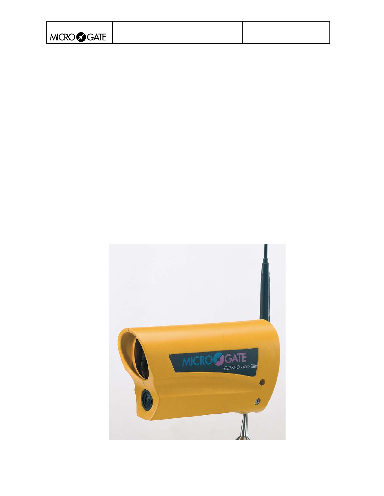
The new Microgate reflection photocell Polifemo is outstanding for its attractive design, conceived
to meet the requirements of safety standards. Its unique optical design guarantees a high range and
greater accuracy of measurement. In addition, special optical and electronic features guarantee
maximum reliability even in poor outdoor light.
Internal power supply is provided by rechargeable batteries (the ‘smart’ recharge circuit is built into
the photocell) which can be replaced with two normal AA size batteries, and allow 18 hours of
autonomous functioning. Its microprocessor management and programming switches also make it a
very versatile instrument.
Radio transmission of an impulse is a critical phase in timekeeping. The timekeeper and/or trainer
have always displayed a certain scepticism towards timing via radio because of the fear of losing
timing data and of inaccurate time taking.
Polifemo-Radio is a highly innovative instrument in the field of radio transmission of timing
impulses. Thanks to technical innovation, the old impulse transmission systems have been replaced
by data transmission which ensures maximum precision and reliability thanks to transmission
redundancy and the use of error correction codes.
Built into the Polifemo-Radio photocell is an EncRadio-SF, the device for radio transmission of
impulses which is part of the LinkGate-SF system. A high-performance top-quality FM radio
module (433MHz 10mW) is used for transmission.
The Microgate Photocell Polifemo-radio
Page 4
POLIFEMO-RADIO
User manual
Doc: POL_R_200_006_E
Version: 2.0
Page
4 of 11
3. POLIFEMO-RADIO
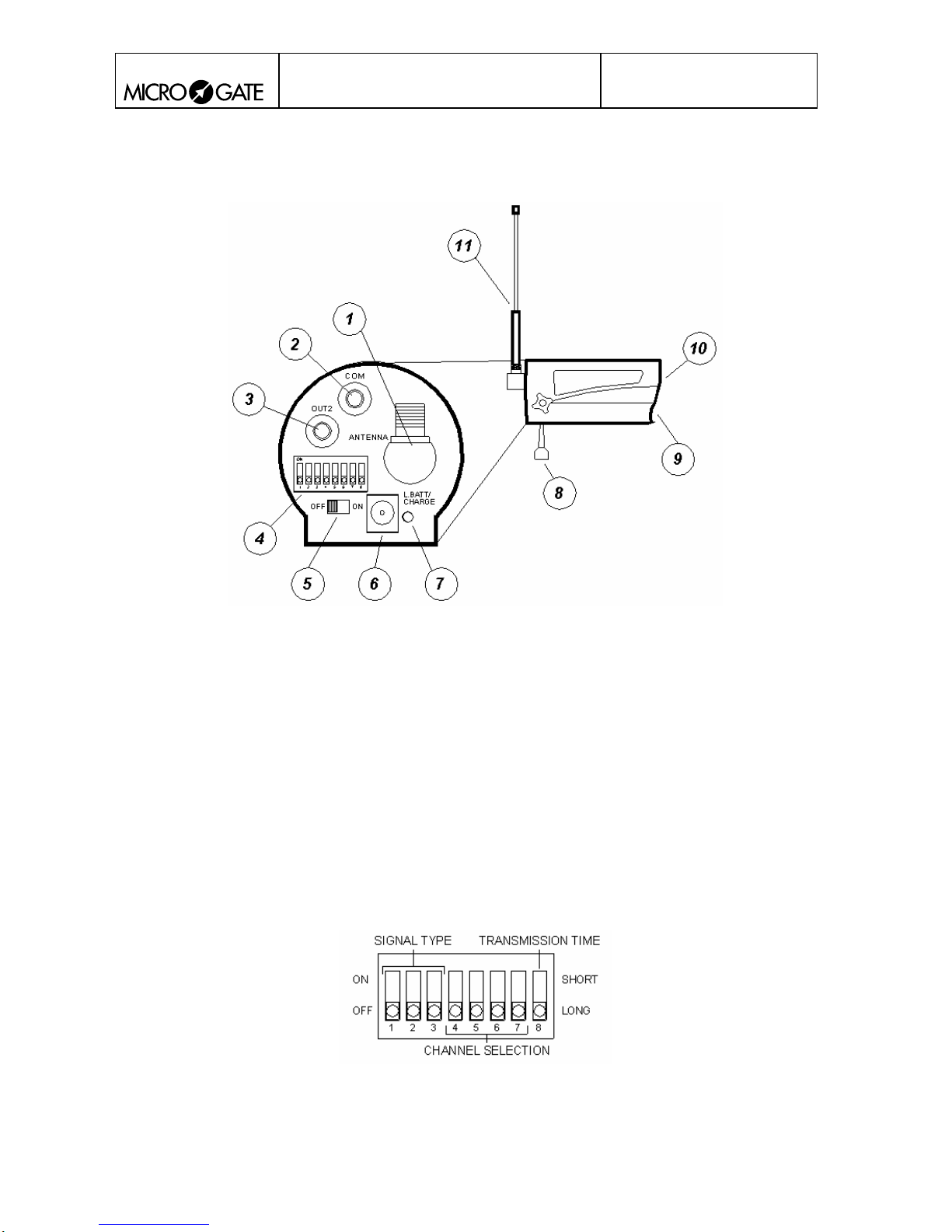
Fig. 1
1. TNC CONNECTOR FOR EXTERNAL ANTENNA CONNECTION
2. COM: Black banana socket
3. OUT2: Green banana socket
4. DIP-SWITCHES FOR SELECTING SETTINGS
5. ON/OFF SWITCH
6. RECHARGE SOCKET
7. SIGNAL LED
8. BALL-JOINT
9. BATTERY COMPARTMENT
10. LENSES
11. EXTERNAL ANTENNA
3.1. DIP SWITCH CONFIGURATION
Fig. 2
Page 5
POLIFEMO-RADIO
User manual
Doc: POL_R_200_006_E
Version: 2.0
Page
5 of 11
4. OPERATING MODES
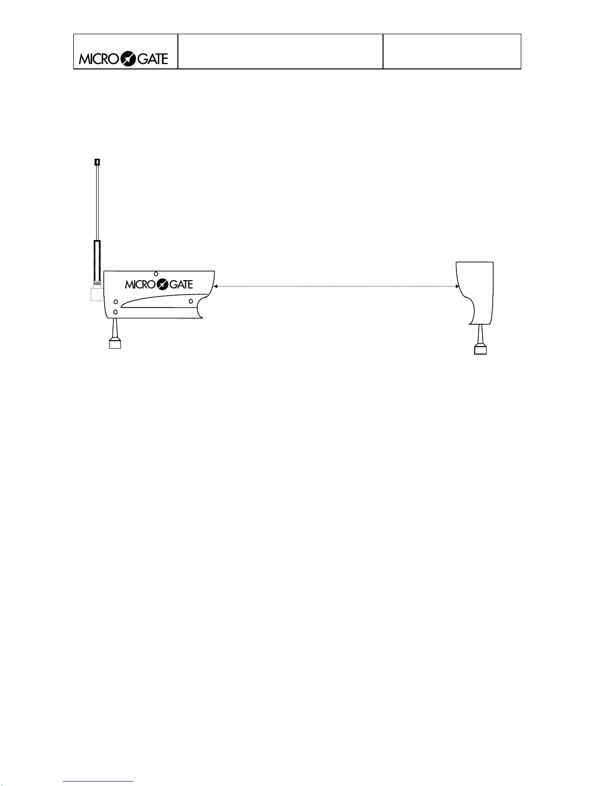
The Polifemo-Radio photocell works by reflection: the maximum operating distance between the
photocell and the reflector is 30 metres.
Fig. 3
Max 30 m
4.1. CENTERING
Centering takes place in the following way: when switched on, the photocell emits a continuous
BEEP, pointing the photocell on the reflector, the BEEP stops, thus indicating correct centering.
5. RADIO TRANSMISSION
The LinkGate-SF system incorporates special technological features to ensure maximum reliability
in the transmission of acquired impulses.
5.1. DIGITAL TRASMISSION OF IMPULSES
EncRadio-SF transmits a set of data (no longer a single impulse!) that contains a large quantity of
information. In particular, the following are transmitted:
• The transmitter’s code (which can be selected with the Channel Select switches)
• The type of signal transmitted (Start, Lap number or Stop, which can be selected with the Signal
Type switch)
• How long ago the event took place.
To the set of data are added numerous control codes and error self-correction codes which prevent a
signal from being incorrectly interpreted during reception.
All the data (information + control codes) are transmitted 16 times, in order to reduce the possibility
of reception failure.
Page 6
POLIFEMO-RADIO
User manual
Doc: POL_R_200_006_E
Version: 2.0
Page
6 of 11
Even with very disturbed signal transmission, this system ensures maximum reliability and
precision (+/- 0.4 thousandths of a second); the complete reception of a single set of data is all that
is required to reconstruct the original time of the event.
5.2. SELECTING THE CHANNEL
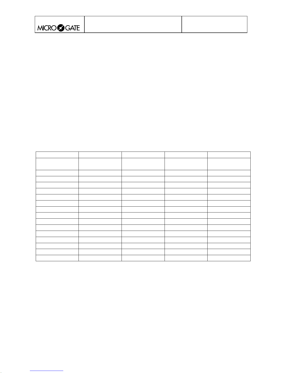
With the 4 CHANNEL SELECTION switches it is possible to set the transmission channel used by
the LinkGate EncRadio-SF (Encoder) module built into the photocell. The transmission channel is
used in such a way that only REI2, Racetime2 chronometers or displayboards
(µGRAPH or µTAB) set to the same reception channel can receive the transmitted signal as valid.
Consult the relative user manuals to identify or select the channel on the various devices. Selecting
the same channel number on the Polifemo-Radio you wish to use will ensure that only signals from
your own timing system are received. This type of filtering of received signals is particularly useful
as the selection of different channels allows the use of a number of systems (chronometer +
Polifemo-Radio) in the same zone without the risk of timing data causing interference.
The following table shows the different channels which can be selected:
SWITCH 4 SWITCH 5 SWITCH 6 SWITCH 7 CHANNEL
ON ON ON ON Disabling radio
transmission
OFF ON ON ON 14
ON OFF ON ON 13
OFF OFF ON ON 12
ON ON OFF ON 11
OFF ON OFF ON 10
ON OFF OFF ON 9
OFF OFF OFF ON 8
ON ON ON OFF 7
OFF ON ON OFF 6
ON OFF ON OFF 5
OFF OFF ON OFF 4
ON ON OFF OFF 3
OFF ON OFF OFF 2
ON OFF OFF OFF 1
OFF OFF OFF OFF 0
Page 7
POLIFEMO-RADIO
User manual
Doc: POL_R_200_006_E
Version: 2.0
Page
7 of 11
5.3. SELECTING SIGNAL TYPE
Switches 1 to 3 make it possible to set the type of impulse you wish to transmit . The following
table summarises the types of impulse available.
SWITCH 1 SWITCH 2 SWITCH 3 Signal type
ON ON ON START
OFF ON ON LAP 6
ON OFF ON LAP 5
OFF OFF ON LAP 4
ON ON OFF LAP 3
OFF ON OFF LAP 2
ON OFF OFF LAP 1
OFF OFF OFF STOP
5.4. IMPULSE TRASMISSION
By using a switch (switch n°8 next to the words TRASMISSION TIME) you can set transmission
duration (approximately 2.3 seconds for long transmission and 0.6 seconds for short). By selecting
long transmission, you will obtain greater redundancy of information as the same data will be
transmitted 16 times. If you select short transmission the set of data will only be transmitted 4 times
so you will have lower redundancy but with a substantial reduction of transmission time.
For normal use, we advise you always to use long transmission (switch n°8 OFF) ) in order to
maximise the redundancy of transmitted data. However, for special applications such as the taking
of several intermediate times very close together, using short transmission is the only practical
solution if transmissions are not to overlap.
5.5. THE RECEIVING DEVICE
The DecRadio_SF modules are powered directly from the Microgate chronometers using the special
connecting cable. It is very simple to use:
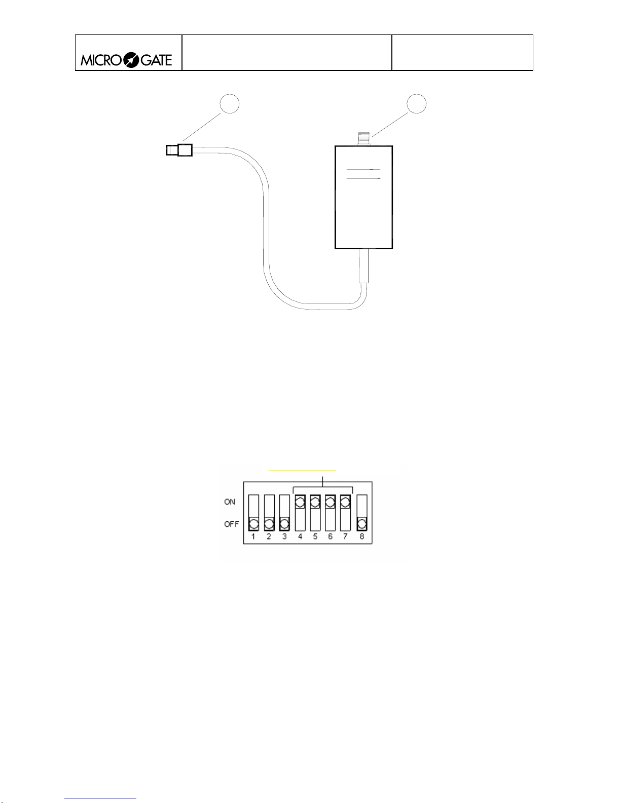
• connect the Nucletron connector (see Fig. 4 N° 2) to the corresponding connector on the
chronometer
• screw in the antenna (see Fig. 4 N° 1)
• check that the channel set on the photocell corresponds to the channel set on the chronometer
(consult the relative manual for the chronometer).
Page 8
POLIFEMO-RADIO
User manual
Doc: POL_R_200_006_E
Version: 2.0
Page
8 of 11
12
Fig. 4
1. BNC for external antenna connection
2. 5 pole Nucletron connector for Radio output
5.6. DISABLING RADIO TRANSMISSION
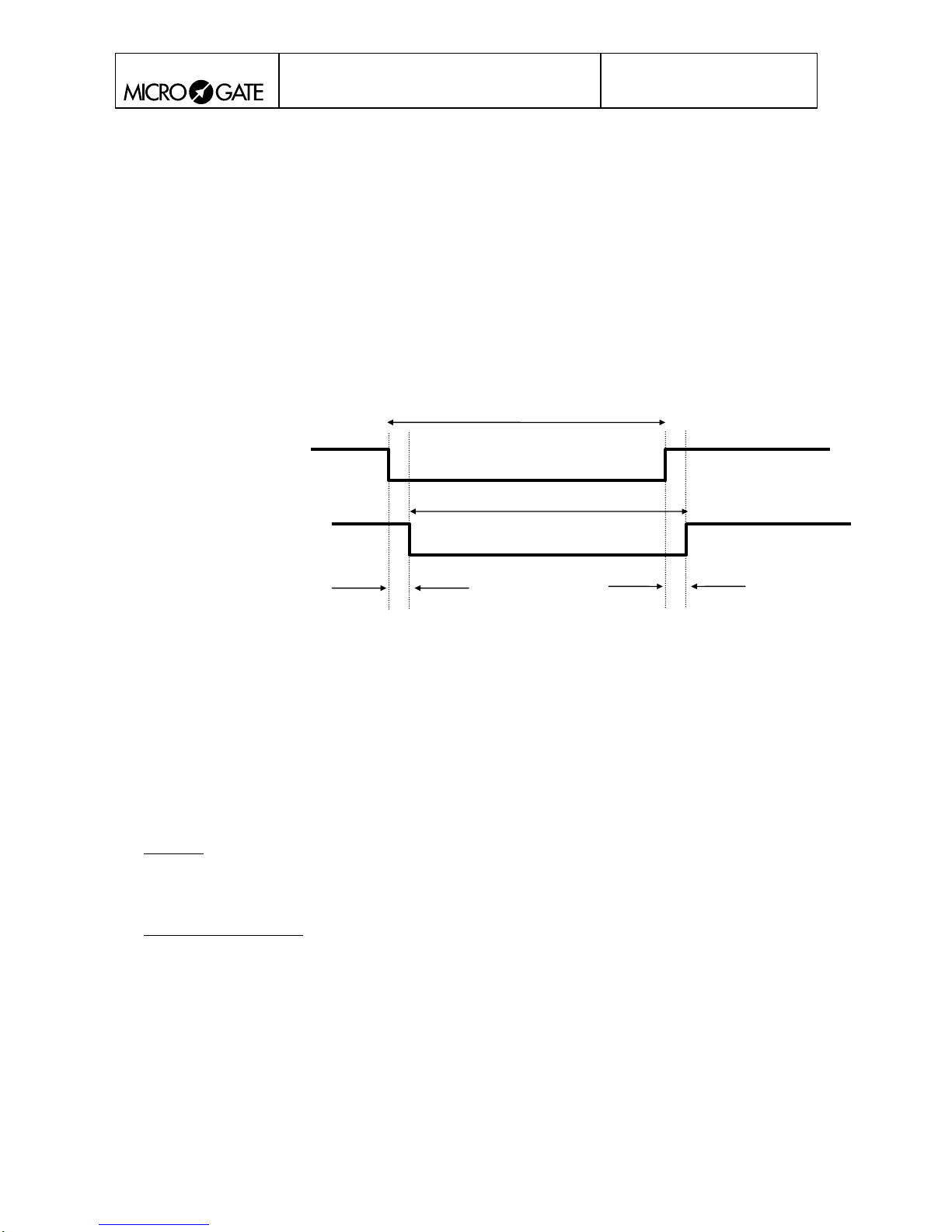
To disable wireless event transmission, set the 4 dip switches of CHANNEL SELECTION
(Switches 4-7) to the position ON (see Figure 5). Switch the photocell off and switch it on again
with the On/Off switch to activate this mode.
Disabling transmission
Figure 5
Page 9
POLIFEMO-RADIO
User manual
Doc: POL_R_200_006_E
Version: 2.0
Page
9 of 11
6. THE OUTPUTS
The Polifemo photocell emits a signal on the output, normally open, and is brought to the reference
level (COM socket – BLACK banana jack) if the infrared beam is interrupted The signal is
presented on the green banana jack (OUT2) and is compatible with every type of timing device.
6.1. OUTPUT SIGNAL
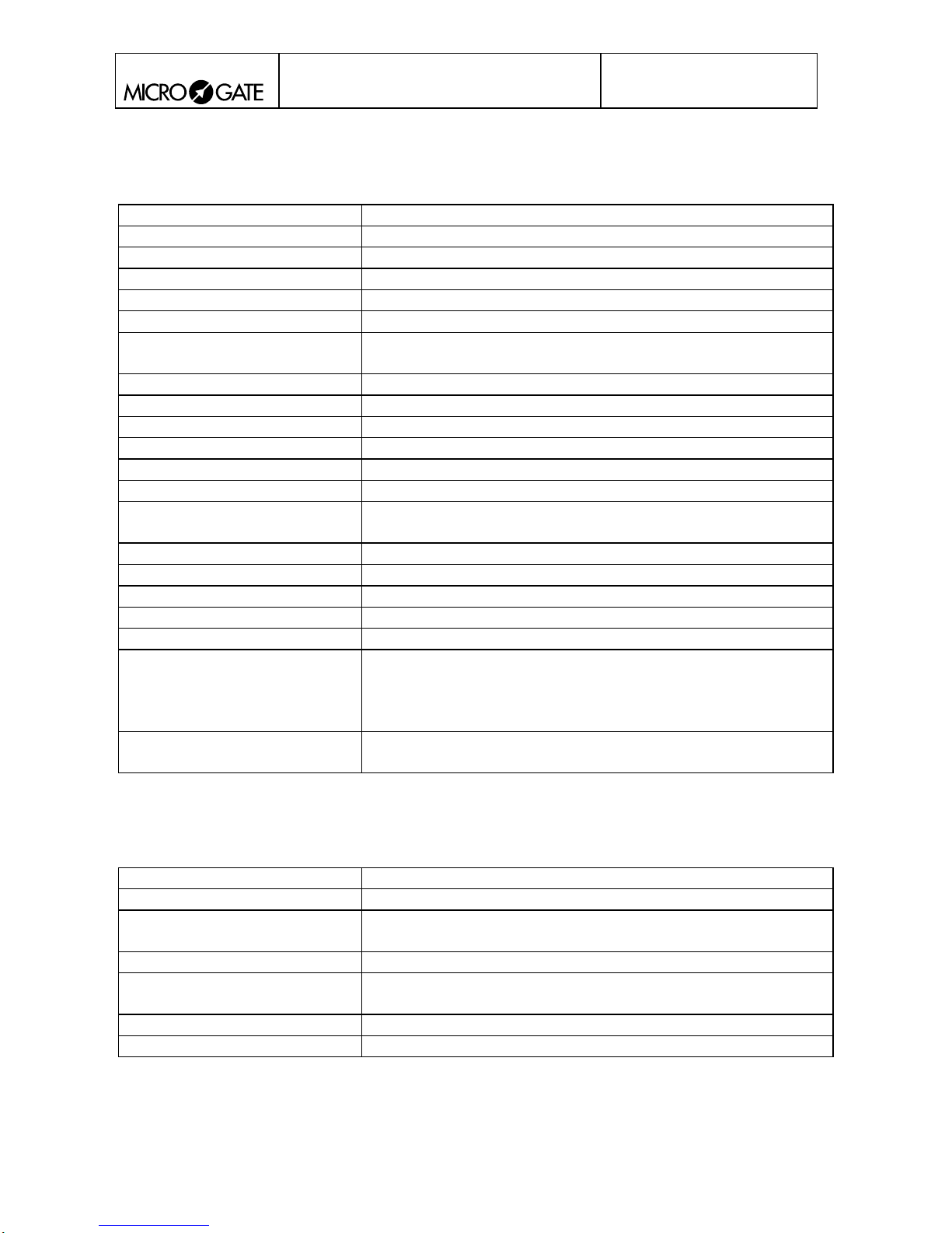
The output signal has a minimum duration of 3 hundredths of a second and has a constant delay
relative to the event of a thousandth of a second. Of course the delay does not affect resolution,
which for Polifemo is 125μs (0.125 milliseconds). The output level passes from high to low
(contact closes) and is kept in this situation until the end of the interruption of the infrared beam
Δ
T
Interruption of beam
Δ
T
Output signal
1 ms
1 ms
7. POWER SUPPLY
The Polifemo photocell can be powered in 2 different ways:
• with batteries
• from recharge power source
Before continuing, it would be better to make clear what the various terms mean:
• batteries: Size AA batteries, both rechargeable and non-rechargeable types;
rechargeable: both NiCd and NiMH 1.2V
non-rechargeable: Alkaline 1.5V
• recharge power source: power applied to recharge jack (see fig 1 n° 6). Voltage must be between
8V and 13V (we strongly advise you not to use voltages above 13V; for higher voltages a
security mechanism - varistor – breaks the supply circuit. The circuit is restored when voltage
has returned within the operative range).
Polifemo can manage both types of power supply simultaneously. If the photocell is on and
powered from an external power source or from a recharge power source, the batteries are protected
by using 'external' power sources; moreover, if recharge power is sufficient, the batteries are kept
charged by a recharge current with a suitable duty cycle.
Page 10

POLIFEMO-RADIO
User manual
Doc: POL_R_200_006_E
Version: 2.0
Page
10 of 11
7.1. RECHARGE MANAGEMENT
Recharging the Polifemo batteries can only take place with the photocell off and is managed
'smartly' by the microprocessor in the photocell itself. The standard procedure is to discharge the
batteries and then to fully recharge them. Recharging starts after insertion of the power supply jack
with sufficient voltage (Vch>8V) and the photocell off.
The following steps are carried out by the program which manages recharging:
STEP ACTIONS LED DURATION POSSIBLE ANOMALIES
1 Checking of
presence of
rechargeable
batteries
Continuous
red
1 minute Presence of non-rechargeable
batteries
2 Battery discharge Continuous
red
variable according
to previous state of
charge
Batteries removed or reach
dangerous voltage levels (faulty
batteries)
3 Battery recharge Blinking
green
7 hours
Batteries removed or reach
dangerous voltage levels (faulty
batteries)
4 End of recharge
and maintenance of
charge level
Continuous
green
Switching on the photocell or lack of recharge voltage result in interruption of the recharge
procedure.
7.1.1. IMMEDIATE RECHARGE
If immediate battery recharge is required without first discharging the batteries, put the switch (Fig.
1
n° 5) to ON for an instant and return rapidly to OFF. The recharge management program will not
first discharge the batteries (steps 3 and 4)
Only in exceptional circumstances should the batteries be recharged straightaway without being
first discharged as this shortens their life.
7.1.2. ANOMALIES
Any anomalies occurring during the recharge procedure are signalled by slow blinking of the red
LED and the sound signal BOOP-pause-BOOP. When an anomaly is detected, the recharge cycle is
interrupted.
Page 11
POLIFEMO-RADIO
User manual
Doc: POL_R_200_006_E
Version: 2.0
Page
11 of 11
8. TECHNICAL DATA
Weight
Size
59 x 180 x 104 (1 x p x h)
Minimum resolution
0.125 ms
Delay in relation to event
1 ms
Temperature of use
-25°C/+70°C
Power supply:
batteries
rechargeable: NiCd, NiMH 1.2V
non-rechargeable: alkaline 1.5V
external power source
4V÷13V with overvoltage-protection
Battery recharge
Built-in “smart” recharge device
Autonomy
18 hours
Processor
8 bit C-MOS microprocessor
Connections
Connections on optoinsulated banana jacks
Optical range
30 m
Transmission mode
Digital FSK transmission; redundancy code with information
accuracy check and self-correction
Radio frequency
433 MHz
Radio transmission power
10 mW
Transmission channelization
Channel 0
Impulse transm. precision
± 0.4 ms
Time base
4 MHz quartz ±10 ppm from -25°C to +50°C
Controls
Dip-switch for selecting type of signal transmitted
(Start, Lap 1..6, Stop)
Dip-switch for selecting long/short signal
Dip-switch for selecting transmission channel
Radio transmission range
About 2 Km
9. LINKGATE_SF DECODER TECHNICAL DATA
Weight
120 g
Size
65 x 50 x 30 mm (l x h x w)
Reception mode
FSK decodifying
Time base
4 MHz quartz
Operating temperature
-25° / +70°C
Power supply
5 Vcc, supplied directly from chronometer
Connections
Cable with 5 pole connector for connection to chronometer
 Loading...