

Page 1

Microframe Corporation
Series 160:
Booster Amplifier
Operating Manual
A0160-7011
*A0160-7011*
Page 2

Page 3

SERIES 160
INSTALLATION & SPECIFICATION GUIDE
ITEM NO: A0160-7011
REVISION DATE: 04/02
Microframe Corporation
604 S. 12th Street
Broken Arrow, OK 74012
Tel: (918) 258-4839
Toll Free: 1-800-635-3811
Website: www.microframecorp.com
E-mail: [email protected]
Page 4

Limited Warranty Agreement
Your Microframe System is warranted against failure
due to defects in workmanship or material for a period of
one (1) year from the date of purchase. Microframe
Corporation will repair or replace any defective unit.
Obvious abuse or mishandling of the unit is NOT covered
by this warranty.
Merchandise Return
If your Unit does not work satisfactorily, please give
us a call. We may be able to clear up the problem by
phone. If it becomes necessary to return your Unit to the
factory, please observe the following.
1. Place Unit in a sturdy box with sufficient packing
material.
2. If requested, include the power supply. It is not
necessary to return the cable and connectors unless they
are the problem.
3. Return the system insured and prepaid since we are
not responsible for shipping damages and losses on
returned Units.
Warranty Service
For warranty service, please contact Microframe at 1-
800-635-3811. A technician will gladly assist you.
Assistance
For any product assistance or maintenance help,
contact Microframe by either calling 1-800-635-3811 or
emailing us at [email protected].
Warning
All power transformers, line cords, and electrical
equipment should be kept out of the reach of children and
away from water. (If you are installing cable in an air
plenum area, such as a drop ceiling used for air return,
you must use plenum-rated cable. The cable supplied
from Microframe is rated CL2 and is approved for installation everywhere indoors except plenum areas.)
Life Support Policy
Microframe's products are not authorized for
use as components in life support devices or systems without the express written approval of the
president of Microframe Corporation. As used herein:
1. Life support devices or systems are defined as
systems which support or sustain life, and whose failure
to perform when properly used in accordance with instructions for use provided in the labeling, can be reasonably expected to result in a significant injury to the user
or any one depending on the system.
2. A critical component is any component of a life
support device or system whose failure to perform can be
reasonably expected to cause the failure of the life support
device or system, or to affect its safety or effectiveness.
Disclaimer
We are constantly striving to improve our products.
Due to this, specifications are subject to change without
notice.
Safety
Do not install substitute parts or perform any modifi-
cation to the product without first contacting Microframe.
Microframe Corporation
P.O. Box 1700
Broken Arrow, OK 74013
1-800-635-3811
Page 5

TABLE OF CONTENTS
MODEL 160 SPECIFICATIONS ................................. 6
1 PRODUCT DESCRIPTION/PRE-INSTALLATION. 7
1.1 BOOSTER AMPLIFIER....................................7
1.2 PRE-INST ALLA TION .......................................7
2 INSTALLATION PROCEDURES ...........................8
2.1 DETERMINE CONFIGURA TION ......................8
2.2 ROUTING THE CABLES .................................8
2.3 DISPLA Y INST ALLA TION.................................8
INSTALLATION DIAGRAM ........................................9
TROUBLESHOOTING CHART................................. 10
Page 6
Microframe Corporation Series 160
MODEL 160 SPECIFICATIONS
Booster Amp
Features
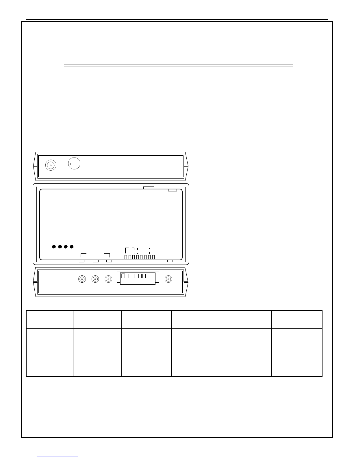
The Model 160 Booster Amplifier is designed to provide
the capability to power additional Visual Pagers. Each
Model 160 can power up to 45 digits of any combination
of Remote Displays depending on distance.
Additional Model 160 Boosters can be added to the
system providing the capability to power a virtual limitless number of Remote Displays.
Microframe® Model 160 Booster Amp
The Model 160 Booster has
LED indicators that assist in
troubleshooting if there is a
GMC Fuse
Fast Blo
2.5 AMP
24 VAC
short in the cable, or the AC
supply is not connected.
STATUS
SOLID=NORM
BLINK= SHORT
SYS SIG OUT
5 VDC
Model 920/4100
Displays Distance
4=2000
5=1700
6=1300
7=1000
10=500
15=200
SYS SIG IN
Model 160
Booster Amplifier
SIGNAL OUT
Model 930
Displays Distance
4=1800
5=1300
6=1000
7=700
13=200
15=100
1-800-635-3811
Broken Arrow, OK 74011
Displays Distance
Model 160 Specifications
Power Input Requirements ........................
Weight of Booster Amp .............................
Weight of Transformer ...............................
6
SIGNAL OUT
Model 940
INPUT
Model 960
SIGNAL
SIGNAL INPUT
GROUND
Displays Distance
4=1200
5=800
6=600
7=500
8=300
9=200
12=100
1=2000
2=1900
3=1100
4=700
5=400
6=300
8=100
Power supplied by 24 VAC, 2.5 Amp
UL & CSA approved Wall Mount
Transformer Requires 115Vac @.7 amps.
1 lb
2 lb
There are 3 RCA outputs and
3 screw down elevator clamps
to ease the installation process.
Model 9620/4600
Displays Distance
1=2000
2=1500
3=800
4=500
5=300
6=200
7=100
Model 4320/9320
Displays Distance
1=2000
2=1900
3=1100
4=700
5=400
6=300
8=100
Support and Sales
800-635-3811
Microframe® Corporation
www.microframecorp.com
Broken Arrow, OK 74013
P.O. Box 1700
Page 7

Microframe Corporation Series 160
1 PRODUCT DESCRIPTION/PRE-INSTALLATION
1.1 BOOSTER AMPLIFIER
The Model 160 Booster Amplifier is designed to provide the capability to power additional Visual Pagers Model 920, 930, 940, 960 or
9600 Remote Displays. Each Model 160 can
power up to 45 digits of any combination of
Remote Displays depending on distance.
Additional Model 160 Boosters can be added
to the system providing the capability to power
a virtual limitless number of Remote Displays.
Installation consists of cabling either with
RG59/U, 18 AWG Paired Wire or 16 AWG
Paired Wire. Once installed, the Model 160
requires no maintenance or servicing.
There are (4) red LEDs located on the top of
the Model 160 that indicate normal operating
status. When first plugged in, the Booster will
not indicate Sys Sig In until the Model 904 is
plugged in and turned ON.
The 5VDC LED indicates the Model 160
Booster is plugged into the power adaptor and
connected to the AC, and the Keypad is also
plugged in and turned ON. If this LED is not lit,
first check the connecting cable from the Keypad and ensure that the Keypad is turned ON.
Next, unplug the Booster and check the 2.5
Amp fuse.
If there is a shorted cable in the system, the
STATUS LED will flash indicating the system
needs to be turned OFF and the problem cor-
rected. Once the short is corrected, the STATUS
LED will remain steadily ON.
The SYS SIG IN and SYS SIG OUT LEDs
indicate the Booster is receiving and transmitting the number from the Keypad to the Remote
Displays.
1.2 PRE-INSTALLATION
Before permanent installation is made, we
recommend that you first test your system and
cables. This will be of great benefit in troubleshooting should you have any problems after
installation. Carefully unpack each part of your
system and record any shipping damage.
SIGNAL LEDs located on the front of the Model
160 are ON.
THIRD, connect a cable from the Output
Connector on the Booster to the Model 920, 930,
or 940 Remote Display.
FOURTH, enter a number into the Model
904 Keypad and see that it is displayed on the
Remote Display.
If there are any problems, proceed to the
Troubleshooting Chart on page 10. If there are
no problems, you are ready to install your
system.
3 ea Model 940
Remote Displays
STATUS
SOLID=NORM
BLINK= SHORT
5 VDC
SYS SIG OUT
SYS SIG IN
SIGNAL OUT
Model 160
115 TO 24 VAC
WALL MOUNTED
TRANSFORMER
115 VAC
Model 904
Keypad
Visual-Pager Series 900
ENTER
DELETE
0
2
13
5
6
4
89
7
To ENTER a paging number, type its digits (press
DELETE if an error is made). Then press ENTER.
A Blinking light indicates a number is being entered.
To DELETE a paging number, press DELETE when the
number is being displayed.
Booster Amplifier
MICROFRAME
C O R P O R A T I O N
Broken Arrow, OK 74011
1-800-635-3811
SIGNAL OUT
GROUND
SIGNAL INPUT
SIGNAL
INPUT
2.5 AMP
Fast Blo
GMC Fuse
24 VAC
115 TO 24 VAC
WALL MOUNTED
TRANSFORMER
115 VAC
160\ax\9702.ai
Model 160
Booster Amp
FIRST, place the Booster Amplifier next to
a 115 VAC outlet close to the Model 904 Keypad.
Plug both the Booster and Keypad in.
SECOND, connect a cable from the Signal
Out connector of the Model 904 Keypad to the
Input Connector on the Booster Amp. Turn on
the Model 904 and observe that the POWER and
7
Page 8

Microframe Corporation Series 160
2 INSTALLA TION PROCEDURES
2.1 DETERMINE CONFIGURATION
The Model 160 Booster Amp will operate
effectively at any point along the cable path
connected to the Keypad. However, to maximize the number of Displays that the Model 160
Booster will drive, locate it within 200 feet of
the Remote Displays it is driving. This may be
next to the Keypad or at the other end of the
cable connected to the Keypad circuit.
The Booster requires a connection to a 115
volt outlet with the 24vac adapter supplied.
2.2 ROUTING THE CABLES
All cable routing should be as straight as
possible with no severe bends that may cause
kinking.
115 TO 24 VAC
WALL MOUNTED
TRANSFO RMER
MO DEL 4600 DISPLAY
BLACK
RED
OUTPUT
SIG
OUT
MO DEL 160 BOO STER
INP UT
SIG
GND
IN
GROUND
BLACK
RED
SIGNAL
RED
115 VAC
8
Visual-Pager Series 4000
0
2
13
6
5
4
8
7
9
To ENTER a paging number, t ype its digi ts (pre ss
DELETE if an error is made) . Then press ENTER.
A Blinking l ight indicates a number is be i ng entered.
To DELETE a pa ging number, press DELETE when the
number is being displayed.
1 1/2 AMP
FAST BLO
MO DEL 4060
REAR VIEW
WITH COVER REMOVED
MO DEL 4600 DISPLAY
REAR VIEW
160\ AX\ 9701.d rw
Page 9

Microframe Corporation Series 160
Model 906
Keypad
Model 906
Keypad
Model 906
Keypad
INSTALLATION DIAGRAM
3 ea Model 960
Remote Display
RED
BLACK
GND
GND
SIGNAL
SIGNAL
SIGNAL
RED
GROUND
INPUT
SIGNAL
GND
SIG
IN
GND
SIG
OUT
OUTPUT
BLACK
3 ea Model 960
Remote Display
BLACK
RED
SHORT JUMPER
Ready 123456
BLACK
Visual-Pager Series 900
1 1/2 AMP
FAST BLO
RED
DELETE
0
2
13
ENTER
160\9703.ai
MODEL 906
REAR VIEW
WITH COVER REMOVED
A/C
AUX
SIG
SIG
GND
GND
89
56
7
4
To ENTER a paging number, type its digits (press
DELETE if an error is made). Then press ENTER.
A Blinking light indicates a number is being entered.
To DELETE a paging number, press DELETE when the
number is being displayed.
TYPICAL INSTALLATION OF 960 SYSTEM WITH MODEL 160 BOOSTER AMPLIFIER
MODEL 160 BOOSTER
3 ea Model 960
Remote Display
115 TO 24 VAC
2.5 Amp
TRANSFORMER
SEE INSTRUCTION MANUAL
FOR CABLE LENGTH AND/OR
REMOTE DISPLAY LIMITATIONS
115 VAC
@.7 AMP
115 TO 24 VAC
WALL MOUNTED
115 TO 24 VAC
115 TO 24 VAC
TRANSFORMER
WALL MOUNTED
TRANSFORMER
WALL MOUNTED
TRANSFORMER
115 VAC
Ready 123456
Visual-Pager Series 900
115 VAC
Ready 123456
Visual-Pager Series 900
115 VAC
DELETE
56
0
89
2
7
13
4
ENTER
DELETE
0
89
56
2
7
13
4
ENTER
To ENTER a paging number, type its digits (press
DELETE if an error is made). Then press ENTER.
A Blinking light indicates a number is being entered.
To DELETE a paging number, press DELETE when the
number is being displayed.
To ENTER a paging number, type its digits (press
DELETE if an error is made). Then press ENTER.
A Blinking light indicates a number is being entered.
To DELETE a paging number, press DELETE when the
number is being displayed.
9
Page 10
Microframe Corporation Series 160
TROUBLESHOOTING CHART
SYMPTOM POSSIBLE CAUSE CURE
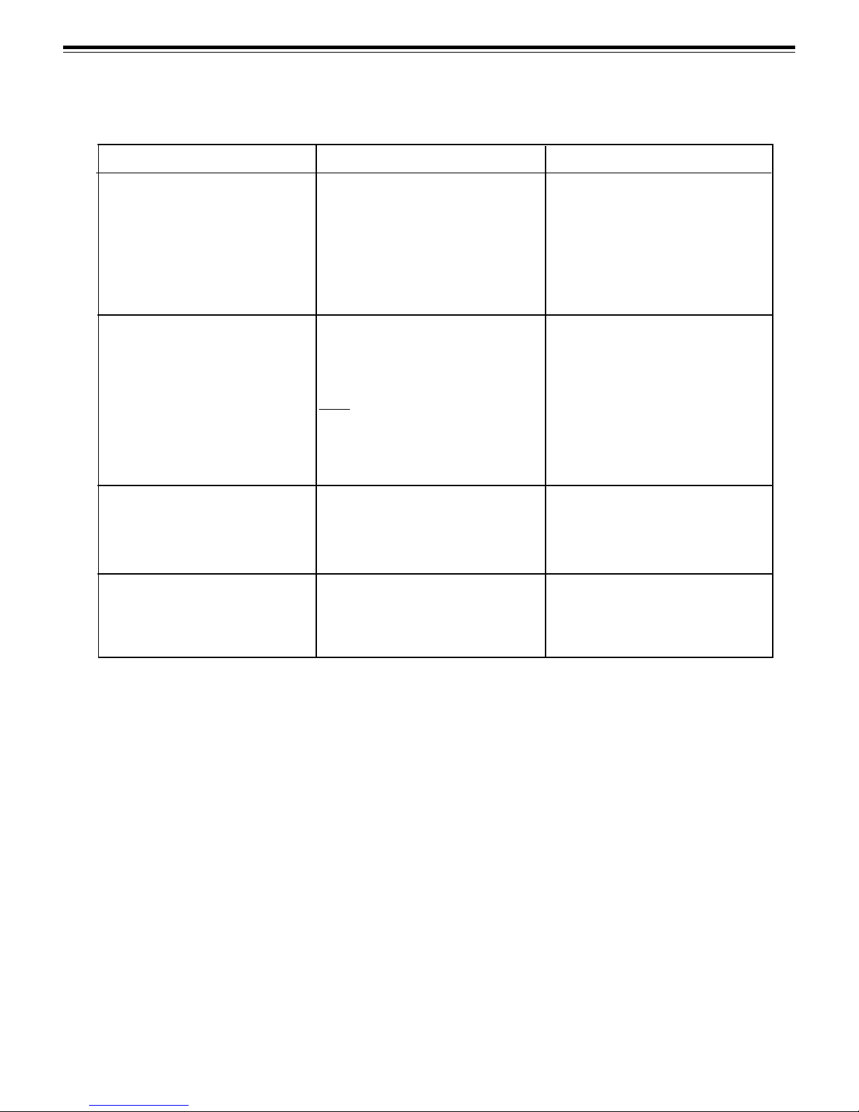
Sys Sig In light OFF
Model 904 Keypad adaptor is not
connected to AC or is not turned
ON.
Bad or no cable or cable connection
from the Keypad to Booster.
Turn ON Model 904.
Check cable and connections.
5VDC light OFF but Sys Sig In
light is on.
Status Light Blinks
Any of the lights pulsate
Booster not connected to AC.
24v AC line fuse blown in Booster.
Note: The power fuse is located on
Rear Panel.
Shorted output cable.
Shorted Remote Display.
Normal Operation.
Connect Booster to 24 Volt adaptor and plug into AC line.
Replace fuse with 2.5 Amp fuse.
Check all cabling for "shorts."
Repair or replace cables.
Return defective Display to factory.
None required.
10
Page 11

Microframe Corporation Series 160
11
Page 12

 Loading...