

Page 1
MICRO FENCE
3
MICRO FENCE EDGE-GUIDE SYSTEM
Email: microfence@microfence.com Website: www.microfence.com
RICHARD WEDLER’S
U.S. Pat. # 5,299,609
Made in the USA
13160 Saticoy St. N. Hollywood, CA 91605 Phone 1-800-480-6427
TABLE OF CONTENTS
PREFACE............................................................................................................................. 2
EASUREMENT – THE CORE PHILOSOPHY OF MICRO FENCE
M
GETTING STARTED............................................................................................................. 2
HECK YOUR PACKING LIST
C
TANDARD ACCESSORIES
S
PTIONAL EDGE-GUIDE ACCESSORIES
O
............................................................................................... 2
.................................................................................................. 3
............................................................................... 3
ATTACHING THE MICRO FENCE TO YOUR ROUTER...................................................... 5
BASIC MEASURING PROCEDURES - “DIAL THE DIFFERENCE.”.................................. 5
MICRO FENCE TECHNIQUES............................................................................................. 7
ADOES
(D
FLUTING
SLOTTING
ABBETING
, R
EEDING
/ R
/ V
EINING
ORTISE
, M
ORMICA TRIMMING
, F
, V-G
& T
ROOVES
ENON
, S
ECESSES FOR HINGES
, R
IRCLES
, C
LIDING DOVETAILS
MAINTENANCE.................................................................................................................. 10
HECKING PARALLEL ALIGNMENT OF THE GUIDE SHAFTS
C
DJUSTING TORQUE OF THE LOCK NUT AND WAVE WASHER
A
LEAN MICRO FENCE IS A HAPPY MICRO FENCE
A C
OUTER ADJUSTMENTS
R
EPLACING WOOD FENCES
R
................................................................................................... 11
............................................................................................... 12
............................................................ 11
READING RECOMMENDATIONS ..................................................................................... 12
.................................................. 2
ORTISING LOCKS
, M
, C
URVED
RREGULAR EDGES
& I
,
)
...................................................... 10
............................................... 11
,
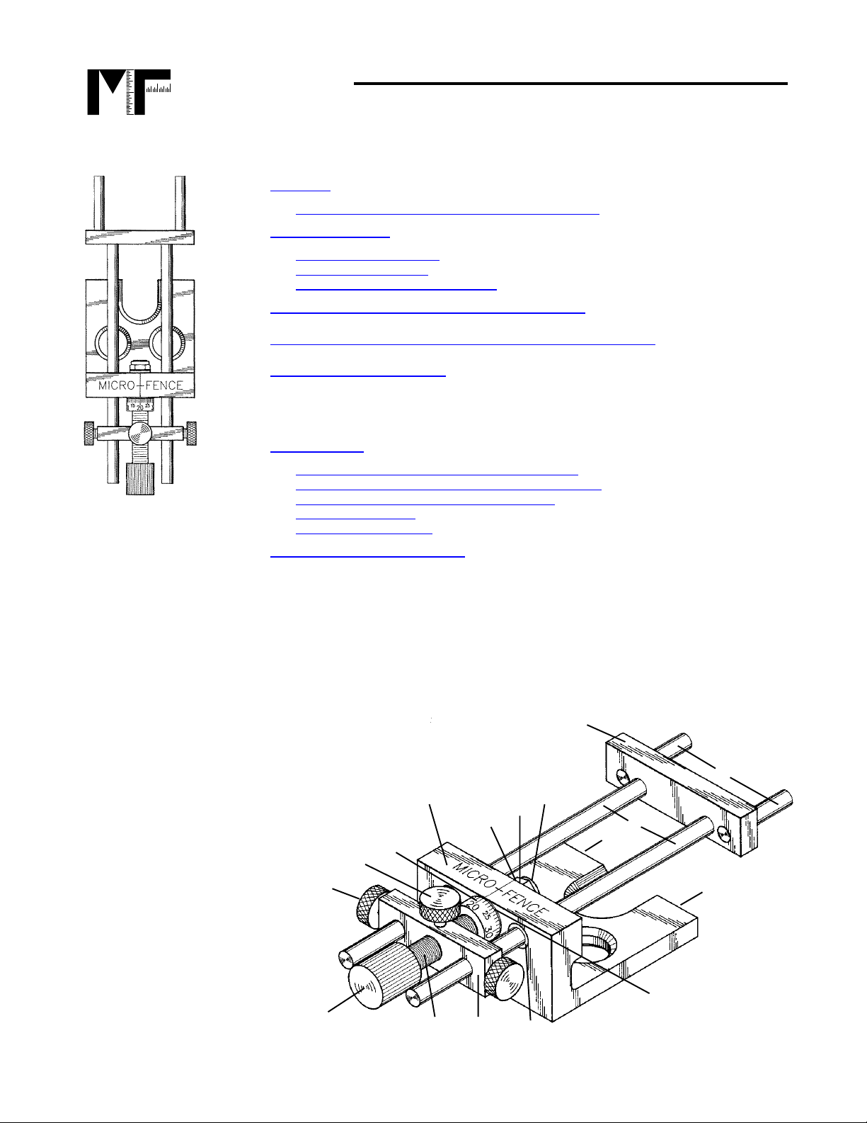
We suggest that you take a few moments and familiarize yourself with the name s of our
parts by referring to the drawing below.
1
Leadscrew adjusting
Knob
2
Brass Locking
Thumbscrews (Long) for
approximate positioning
3
Brass Locking
Thumbscrew (Short) for
Spindle Locking
4
Stainless Steel Lead
Screw/Spindle
5
Laser-Etched
Micrometer Dial
6
Spindle Bar
7
Main Body
8
Mounting Bar
(Interchangeable to
fit other routers)
9
Stainless S teel Guide
Shafts
10
Mounting Pins (Vary
according to router
model)
11a
8-32 Tapped holes
(To attach wood
fence or half-rounds)
12
Press fit bushings
13
Thrust Washer
14
Thrust Washer
5
2
1
7
4
15
Me t al Wave Washer
16
Lock Nut
16
15
14
6
12
8
10
9
11a
11a
13
Fig. 1
1
Page 2
MICRO FENCE
MICRO FENCE EDGE-GUIDE SYSTEM
Email: microfence@microfence.com Website: www.microfence.com
PREFACE
Measurement – the core philosophy of Micro Fence
13160 Saticoy St. N. Hollywood, CA 91605 Phone 1-800-480-6427
Most woodworkers would probably agree that the router is
the
most versatile tool in the
woodshop. We contend that an edge guide is the most versatile accessory that works with
the router. It can do a myriad of different woodworking jobs. Whether the work piece is
straight or curved, the primary function of the fence is to guide the router bit in a path parallel
to the edge. Your Micro Fence is the first and only edge guide to provide you with reliable
and accurate settings of the distance between the fence and the router bit. Borrowing directly
from the machine-tool trade, it features a built-in micrometer that measures in thousandthsof-an-inch to make
any
set-up precise, efficient and repeatable.
GETTING STARTED
Check Your Packing List
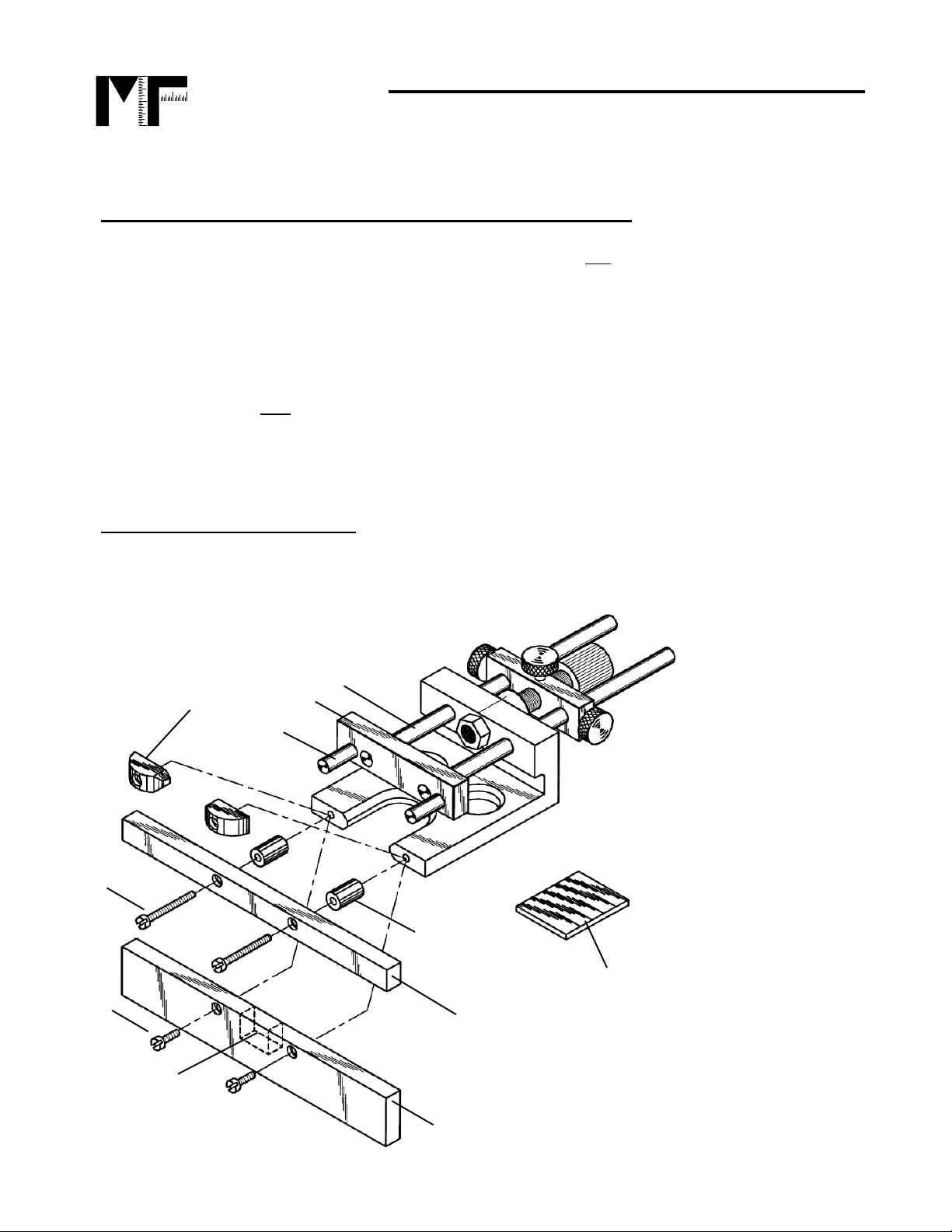
Your Micro Fence comes with the parts and accessories shown in Fig. 2. These standard
accessories make your fence an extremely versatile tool.
Fig. 2
9
19
8
19b or c
19a
2
18a
19d or e
11
18
8
Mounting Bar
9 Stainless Steel Guide Shafts
10
Mounting Pins
11
Low Profile Wood Fence
18
Deep Profile Wood Fence
18a
Notch for bit pass through
19
Half-round inserts
19a
8-32 x ½” Fillister Screw
19b
8-32 x 1¼” Fillister Screw
19c
8-32 x 1¾” Fillister Screw
19d
5/8” Delrin Spacers
19e
1¼” Delrin Spacers
D
Rubber Pad
D
Page 3

MICRO FENCE
MICRO FENCE EDGE-GUIDE SYSTEM
Email: microfence@microfence.com Website: www.microfence.com
Standard Accessories
13160 Saticoy St. N. Hollywood, CA 91605 Phone 1-800-480-6427
Either the
low profile
(#11), or
deep profile
(#18)
wooden fence faces
may be attached to
the main body, (using the 8-32 tapped holes on the end of the Micro Fence body, (Fig. 1,
#11a)). The low profile is useful for most straight-line operations occurring inboard from an
edge, and will clear ¾” material on a work bench or work surface. The height of the deep
profile fence allows it to be notched, (Fig. 2 # 18a), so that the bit can be enveloped by the
fence for rabbeting or flush-trimming operations. It’s also useful for shallow “pocket” cutting
as required for stopped flutes, lock or hinge recesses, dados or mortises.
A pair of
Delrin half-round inserts
(#19) comes with each edge-guide. When installed on
the main body, (using the same Fig. 1, #11a holes as the profile fences), they provide two
points of contact so the fence can ride along arcs, circles or irregular edges. (See Fig. 2).
Note: Since the inserts mount on 2” centers, using the edge guide on small radiused edges,
(particularly under 2”), is not only difficult, but will result in a cut that is not parallel to the
edge.
A pair of
Delrin extension spacers
(#19d or e) is included to provide additional reach,
permitting settings that align the fence with the far side of the bit for flush-trim operations,
such as Formica or veneer trimming. A second, longer set of 8-32 screws, either 1¼” or 1 ¾”
(#19b or c) depending on which router your fence fits, is provided in your parts bag for
installation of the extensions.
Rubber pad
(D): The black rubber pad included in your parts bag prevents the jaws of pliers
from damaging the stainless steel guide shafts or mounting pins during installation and/or
removal. (Care should be taken that the plier’s teeth are not so sharp as to cut through the
pad when pressure is applied).
Optional Edge-Guide Accessories:
Mounting Bars
for Different Routers: The Micro Fence System can be
adapted for use on virtually any router or laminate trimmer on the
market today simply by changing the mounting bar and pins
(Figs.1 & 2, #’s 8 & 10). The guide shafts, (Figs.1 & 2, #9)
are threaded and can be changed out easily.
Sub-base Assemblies:
These allow the Micro Fence System to be used
Mounting Bar
on laminate trimmers. These sub-bases come with two cross-drilled
posts that provide points of attachment.
Our
Stop Collar Sets
are matched sets of four brass collars fitted with nylon-tipped
setscrews. Locking the collars on the guide shafts allows you to “memorize” the position of
the guide for a particular cut and return to it to that position later, without having to re-
3
Page 4
MICRO FENCE
MICRO FENCE EDGE-GUIDE SYSTEM
Email: microfence@microfence.com Website: www.microfence.com
measure. (A, B and C in the diagram to the right represent possible stop
collar placements). They may be used to locate cuts that must be in
relation to one another, (such as flutes or reeds); to memorize the
amount of offset when enlarging single cuts with a second pass,
(dadoes for under-sized plywood); or, when installed on our
Circle Jig, to position concentric cuts, (like the inside and
outside diameters of a ring or wheel).
13160 Saticoy St. N. Hollywood, CA 91605 Phone 1-800-480-6427
The
Circle Jig Attachment (CJA)
: Our Circle Jig Attachment can be mounted
on the guide shafts (Fig.1, #9) in place of the edge guide for circular
cutting requirements. The standard attachment allows you to rout
circles and arcs from 6 in. to 48 in. in diameter. Longer rods
(24” or 36”) are available for larger diameter work.
The following accessories are available for use with our Circle Jig:
Stabilizer Bars:
These maximize the rigidity of our Circle Jig
when making larger circles or taking heavier cuts. A clamping
device, stabilizer bars grip all four rods of the jig o nce your
final settings have been made, shown here on the Circle Jig
Complete.
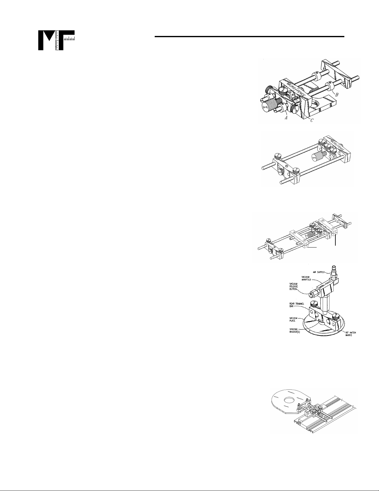
Vacuum Center Accessory (VCA):
This accessory eliminates the
need to drill a pilot hole to secure the center pivot when routing circles.
Your air compressor provides the vacuum necessary to hold the center
in place. Developed initially for the solid surface and formica trades,
the VCA can provide efficient set-ups and unblemished work surface
on any cabinet-grade material including plywoods and surfaced
lumber.
Circle Jig Attachment
Stabilizer Bars
Ellipse Jigs:
When connected to the two centers on this jig, our Circle Jig can cut ellipses
or ovals in a great variety of shapes and sizes. The Ellipse Package provides all the plates,
centers, slides and linkage you need to turn your Circle Jig into a far more versatile tool.
“Tru-Grip Clamp” Interface:
By fitting this accessory to our
Circle Jig, the Micro Fence will slide along the extrusion of a
“Tru-Grip Pro Ft’r” clamp. This guides the router in a straight line,
for dadoes, grooves or decorative cuts across any flat surface.
See our latest brochure or visit our website at www.microfence.com for more information and pricing on our accessories.
4
Page 5

MICRO FENCE
MICRO FENCE EDGE-GUIDE SYSTEM
Email: microfence@microfence.com Website: www.microfence.com
ATTACHING THE MICRO FENCE TO YOUR ROUTER
The Micro Fence you ordered includes the appropriate mounting
bar, pins and screws to fit the router you have specified. Once
you have removed the fence from its packaging and checked
all parts for tightness, simply slide the mounting pins into
the existing holes in your router’s base and install the
screws we supply to lock the fence onto the router.
(If your router already has the necessary
locking screws, keep the set supplied
with your Micro Fence for backup.)
Tip:
using your edge guide. These include the mounting pins and guide shafts where
they are threaded into the mounting bar, the screws holding the fence on the router,
and the brass locking thumbscrews that position the fence and lock the spindle.
13160 Saticoy St. N. Hollywood, CA 91605 Phone 1-800-480-6427
Fig. 3
Care should be taken to check that all threaded joints are firmly tightened before
BASIC MEASURING PROCEDURES
“Dial the Difference.”
The Micro Fence was designed to allow very accurate adjustments when using it in
conjunction with a dial caliper. Both tools are calibrated in .001 increments. To set the router
for any basic cut, use this simple
Loosen the two brass locking thumbscrews (Fig. 1, #2), and preset the Micrometer
Tip:
two-step
method:
Dial to 0.50 (it’s the same as zero), before starting. This practice makes the
arithmetic between cuts simple.
Step 1:
Set the fence at a position that approximates the distance between the edge of the
stock and the desired router bit cutting location. Make a test cut on a piece of scrap wood.
Step 2:
Measure the distance between the edge of the work piece and the cut with your dial
calipers.* Calculate the difference between this measurement and the desired measurement
(by simple subtraction), and then use the adjustment dial on the Micro Fence to reposition
the fence relative to the bit by this amount.
Example A:
Measuring the test cut shows an edge-to-bit distance of 1.133” inches. The
desired distance is 1.250”, (a difference of .117”). The adjustment dial is used to move the
fence .117” farther away from the bit.
The two most common measurements are 1.) the size of the cut itself and/or 2.) the distance the
*
cut occurs from an edge or previous cut.
5
Page 6

MICRO FENCE
MICRO FENCE EDGE-GUIDE SYSTEM
Email: microfence@microfence.com Website: www.microfence.com
Tip:
pushes it away. Remember that routers rotate clockwise, (when viewed from
above). Your feed should be counter-clockwise in most operations to avoid “climb
cutting.” Take it easy.
13160 Saticoy St. N. Hollywood, CA 91605 Phone 1-800-480-6427
Turning the spindle clockwise draws the bit toward the fence; counter-clockwise
NEVER force your router in any application
.
Example B:
Here’s another way you can use Micro Fence’s precision ad justability to your
advantage:
Lumber and plywood today aren’t usually precise in their dimension, (e.g., ¾” plywood is
frequently manufactured as much as 1/16” under-size). If it were full size, a ¾” piece would
measure .750”. In reality, however we frequently find goods that measure anywhere from
.690 to .750. When a snug fit is crucial for joinery or aesthetic considerations, you can use
the Micro Fence with an under-sized bit to create tight fitting joints.
Let’s say the plywood parts you wish to join measure .710” thick. Starting with a 5/8 in.
diameter straight bit, rout a groove and measure its width (bits don’t always cut exactly the
size they’re supposed to). If it measures .625” wide, adjust the dial on the Micro Fence to
reposition the fence by .085” (subtract the actual cut dimension from the thickness of your
material), then take second cut. The second pass will widen the gro ove to .710” to fit your
plywood.
It’s always a good idea when cutting joinery to include a little clearance. When joining
Tip:
¾” plywood, for instance, we recommend routing grooves or dadoes .010 -.015 wider
than the stock’s thickness (.720” - .725” for the example above). This makes joints
easier to assemble and allows room for the wood to swell when glue is applied to the
joint.
Reading Calipers
This example reads .818”. Read the inch
and/or 1/10 inch from the scale on the beam
(.800”). Read the 1/100 and 1/1000 inch from
the dial (.018”).
To set zero: Wipe the lower jaw faces clean and
loosen the bezel locking screw (under the Dial).
Close the two lower jaws and rotate the bezel
until the needle points to zero. Re-tighten the
bezel lock to secure the bezel ring in its new
position.
Your calipers will measure inside, outside,
depth and offset dimensions. It can also be
used as a gauge by setting the beam locking
screw at whatever dimension you wish to test.
:
6
Inside
Measurement
Outside
Measurement
Bezel
Lock
Beam Lock
Beam
Thumb
Wheel
Page 7

MICRO FENCE
MICRO FENCE EDGE-GUIDE SYSTEM
Email: microfence@microfence.com Website: www.microfence.com
MICRO FENCE TECHNIQUES
There are many routing jobs that Micro Fence makes easier and more precise. Below are
some examples of these jobs and the techniques we recommend for their execution.
I. Dadoes:
To cut any size dado, use the technique described in Example B on page 6. Make an initial
cut with a bit smaller than the thickness of the stock you’re working with, measure the first
cut, then take a second pass after adjusting the fence to widen the first cut by the desired
amount. Dadoes of virtually any width can be accomplished with this two-cut method.
13160 Saticoy St. N. Hollywood, CA 91605 Phone 1-800-480-6427
a. Parallel Dadoes: Fitting your Micro Fence with the
Circle Jig Attachment allows you to rout any number
of straight, parallel dadoes. First, attach the aluminum
fence supplied with the Circle Jig to the bottom of
either trammel bar. The aluminum fence is designed
to reach down into the last cut you made, allowing you
to make repetitive dadoes at equal spacing, (or at any
spacing you choose).
II. Rabbeting:
Rabbet cuts can be accomplished with the same two-cut approach used for
dadoes. Notching the deep profile wooden fence, (Fig.2, #18a), will let you use any portion of
your router bit. Measure your first cut with the back end of your dial calipers and then dial the
appropriate adjustment for any dimension you require.
III. Mortise and Tenons:
The Micro Fence can help you cut snug-fitting mortises using the same basic two-cut
approach described above in the dado section.
a. The tenon can be cut most efficiently on the table saw, making vertical and
horizontal passes against the saw fence. Once it is cut, measure it with a dial
caliper to determine its width and length.
b. Draw a center line on the stock that is to receive the mortise and rest the tenon on
it to mark the limits of the mortise cut using the tenon itself for your template.
c. Using a multi-spur or Forstner bit in a drill press, drill along the center-line to clean
out the majority of material fro m the mort is e .
d. Set your Micro Fence, with the deep-profile wooden fence installed, at an
approximate distance a little shy of the finished tenon dimension and take a cut
from each side of the stock. (The bit should be cutting on the far side of the
mortise from where the wood fence is riding). This technique will automatically
center the cut on your stock.
e. Measure the result of these initial cuts with a dial caliper.
f. Dial ½ of the difference between the existing mortise and the size of the tenon you
wish to accommodate, add ½ of any clearance you’d like to have, and make your
final cuts.
7
Page 8

MICRO FENCE
MICRO FENCE EDGE-GUIDE SYSTEM
Email: microfence@microfence.com Website: www.microfence.com
IV. Recesses for Hinges:
13160 Saticoy St. N. Hollywood, CA 91605 Phone 1-800-480-6427
a. Butt hinges: First measure the width of the hinge leaf. Place the fence at an
approximate setting with either the low or deep profile wooden fence face installed
on the Micro Fence body. Measure the test cut, and then adjust the setting to
accommodate the width of the leaf. Draw pencil lines on the door edge to show the
length of the hinge. Once the recesses are cut, chisel out the radius corners left by
your router bit with a sharp paring chisel.
b. SOSS Hinges: This “invisible” hinge offers an attractive alternative to standard
hinges, but has always presented some difficult challenges with its installation
requirements. Two cuts of differing length and depth must be made on the same
centerline. A first, deeper cut to house the body of the hinge is followed by a
second, more shallow one to accept the face plate. The centerline for these cuts
can be found by running one test cut at an approximate setting in scrap material
the same thickness as your finished piece. Measure the material left on each side
of your test cut and dial one half the difference between them in the appropriate
direction.
V. Mortising Locks:
Centering the mortise for a lock or strike plate can be easily accomplished by taking one test
cut in material the same size as that of your actual piece. Measure the material left on either
side of your cut and compare them. Dial one-half of their difference in the appropriate
direction to position the bit precisely on the centerline of the work.
VI. Fluting/Reeding:
a. Three or Five Flute Groupings: Assuming your stock is straight and parallel, a
centered flute is first routed, from which other cuts are referenced. On a piece of
scrap material of the same width, run a test cut at approximate position. Measure
the distance from the edge of your material to the edge of the cut flute on each
side. Dial one-half the difference between these two measurements in the
appropriate direction to center the cut. Successive flutes are placed using the
same test cut principle, though your correcting cuts are no longer divided in half.
b. Four Flute Groupings: Your first approximate setting is used to make cuts from
each side of the work piece. This leaves a “land” in the center, which is the
dimension you will match after re-setting the fence for the next two flutes. Do your
test cut, and then dial the difference to the proper setting and run the “outboard”
flutes.
c. Note: Our Stop Collars can be used to “memorize” a cut position before resetting
the fence to another position. Inlay Work:
Measure the inlay you wish to install. If its dimension doesn’t match the diameter
of a standard router bit, pick a bit of smaller dimension. After an initial inlay recess
is cut, enlarge it with a second pass by dialing the desired dimension on the Micro
Fence. We recommend a trial run in scrap material to insure desired results before
8
Page 9

MICRO FENCE
MICRO FENCE EDGE-GUIDE SYSTEM
Email: microfence@microfence.com Website: www.microfence.com
TIP:
This allows an element of insurance if the fence wanders away from the edge during
the first pass. The second cut, after adjusting the fence outward, will clean up any
irregularity.
VII. Formica Trimming:
Setting up your router with the bit flush to the front surface of the deep-profile wooden fence
allows you to make “flush-trim” cuts, such as those needed to trim formica or wood veneer.
Settings can be tested and adjusted in one-thousandth-of-an-inch increments for immaculate
flush cuts.
These setups may require that the wooden fence be notched to allow the bit to be positioned
inside it and to extend far enough below the sub-base of the router to cut through the
thickness of the material you wish to trim. Each Micro Fence is designed with sufficient
clearance between the router sub-base and the top of the fence to accommodate the
thickness of plastic laminate. Two delrin spacers (either 5/8” or 1 ¾”) are included with each
edge guide to provide additional reach for this type of setup. (See Fig. 2, #19d or e).
13160 Saticoy St. N. Hollywood, CA 91605 Phone 1-800-480-6427
doing the final installation in your actual project. (Allowing .002-.003 tolerance may
prevent the inlay material from splitting or breakage during installation).
When installing inlay in curved or circular pieces, always cut the inside radius first.
VIII. Circles:
Our Circle Jig Attachment accessory works in conjunction with our basic edge guide or can
be purchased as a totally separate tool (called the Circle Jig Complete). The CJA simply
slides on to the same guide shafts, (Fig. 1, #9), and provides a trammel pin from which to
swing the router to perform radius cuts. The standard attachment provides capability for 6”48” diameters. Longer rods are available for diameters up to as large as 12 feet. A separate
instructional booklet comes with each Circle Jig Attachment.
IX. Straight Edges – Edge Profiling:
The deep profile wooden fence, (Fig.2, #18), can be
installed with the extensions provided in your parts bag, (Fig.2, #’s 19d or e), to reach
settings that “envelop” the router bit completely or in part. When completely enveloped, flush
trimming can be accomplished, (see VII above). Partial enveloping of your bit will allow edge
profiling for details like bevels, ogees or over-rounds.
X. Curved and Irregular Edges:
a. Installing the half-round inserts (Fig.2, 19) provides two points of contact with your
workpiece to allow your fence to follow curves.
b. Using angled or curved fences to guide cuts: You can use the drilled and tapped
holes on the end of the Micro Fence body, (#11a in Fig. 1, p.1), to attach any sort
of attachment that you fabricate yourself. e.g. “V” shaped wooden fences to follow
circles.
9
Page 10

MICRO FENCE
MICRO FENCE EDGE-GUIDE SYSTEM
Email: microfence@microfence.com Website: www.microfence.com
13160 Saticoy St. N. Hollywood, CA 91605 Phone 1-800-480-6427
XI. Slotting and Veining:
XII. “V” Grooves
are frequently used in desk or table-top construction to separate solid
See VI above.
wood surrounds from plywood center fields. “V” grooves allow different rates of expansion
and contraction to occur without cracking finishes. As a design element, they add a sense of
depth to a surface or to separate contrasting woods for dramatic effect.
XIII. Sliding Dovetails:
Useful in the manufacture of table or drawer extension slides, these sliding joints can be
made to whatever tolerances are necessary given the species of wood you’re using.
Hardwoods like maple or beech are popular choices. The control over tolerances that your
Micro Fence provides can produce silky smooth travel. Test cuts and measurement of the
pin or tail dimensions will tell you how far to move the fence on successive passes to
produce the results you prefer. (As a bench- mark starting place, include approximately .010”
clearance).
MAINTENANCE
Your Micro Fence has been thoroughly checked during it’s assembly for smooth and
accurate operation. There are a number of alignments and tension adjustments that are
critical to the unit’s proper functioning. In the normal course of use, you may need to check
these settings and readjust them if necessary.
Checking parallel alignment of the guide shafts
The guide shafts (either 7” or 12”) must be parallel to one another in both horizontal and
vertical planes (see Fig 1, #9). Test the vertical alignment by simply placing the mounting
bar and guide shaft assembly on a smooth, flat surface (a table saw, jointer bed, etc.), and
tap lightly on the end of each guide shaft with the tip of your finger. Any motion indicates a
misalignment that will adversely affect the way in which the shafts slide through the body and
spindle bar.
Apply pressure in the appropriate direction
to correct the misalignment and re-test on
the flat surface. Pay special attention to insure
that the readjustments have not loosened the shafts
in the mounting bar. If necessary, re-tighten, using the
rubber pad and either your fingers or pliers to achieve
firm tightness.
The horizontal alignment can be checked visually by
simply installing the guide shafts in the main body of the Micro Fence. They should slide into
the Delrin bushing without deflection, and pass on through the appropriate holes in the
spindle bar without significant resistance, (though a little is OK). Fluid motion should be
checked by sliding the guide shaft/mounting bar assembly back and forth a few times.
Fig.4
10
Page 11

MICRO FENCE
MICRO FENCE EDGE-GUIDE SYSTEM
Email: microfence@microfence.com Website: www.microfence.com
Be sure to tighten all threaded parts. A loose gu ide shaft will compromise the rigidity of your
edge guide. This holds true for the mounting pins as well.
seated.
Adjusting torque of the Lock Nut and Wave Washer
The “feel” (tightness or looseness) of the adjustment screw (spindle) can be set by
increasing or relieving the compression of the wave washer (Fig 1, #15), located between
the two Delrin thrust washers (Fig 1, #14) under the nylock nut (Fig 1, #16). The lock nut
requires a 7/16” wrench. Th e more tightly co mpressed the wa ve washer is, the stiffer th e feel
of the spindle as it turns. If excessively loosened, lateral deflection of your fence is possible.
As a rule, the nylock nut should be as tight as possible without making the spindle
uncomfortably difficult to turn with your thumb and forefinger.
Cleaning your Micro Fence
13160 Saticoy St. N. Hollywood, CA 91605 Phone 1-800-480-6427
Keep all threaded parts
firmly
Keep your Micro Fence as clean and dust-free as possible with compressed air or a soft
brush. An occasional drop of light oil under the spindle lock thumbscrew will keep the lead
screw turning smoothly. Our choice is Phil’s Tenacious Oil, which can be purchased at
many bicycle shops. We recommend cleaning and lubricating the stainless steel guide
shafts with a good silicone-free dry lubricant. At our fa ctory, we use Dynaglide during the
assembly process. If you wish, it can be ordered directly from us by calling
800-480-6427.
Router adjustments
Router motors operate at high rpm, and typically are prone to vibration from even slight misalignments. Collet wear and accumulated dirt can have a negative effect on the way the bits
rotate and cut. Other factors that affect a router’s cutting quality include the sharpness and
accuracy of the bits’ edge grind, and concentricity of the bits’ cutting surface relative to the
shank. Keep your router clean and in good working order and buy only good quality router
bits. Use only sharp bits. (Easy-Off oven cleaner works well to remove pitch.)
Under normal circumstances, the brass thumbscrews that lock the stainless steel guide
shafts and adjustment-screw spindle should withstand router vibration and hold fast.
However, if there’s lots of vibration (some routers simply vibrate more than others), the
thumbscrews may loosen and subsequently cause your edge-guide to slip out of position. If
this occurs, we strongly recommend first checking the router’s collet for wear. Improper bit
installation or over tightening can cause the collet to become “sprung”, and affect its gripping
capability or the trueness of the bits’ rotation. Installing a slice of rubber tubing with ¼” I.D.
under the heads of the thumbscrews can help to absorb excess vibration and prevent
inadvertent loosening.
It is normal for the brass lock-screws on your Micro Fence to tarnish. Their original luster can
be restored by polishing them with fine steel wool or Scotchbrite abrasive pads. We use a
drill press or cordless drill with hand-tightened chuck to spin them while firm pressure is
applied with the polishing material.
11
Page 12

MICRO FENCE
MICRO FENCE EDGE-GUIDE SYSTEM
Email: microfence@microfence.com Website: www.microfence.com
Replacing wood fences
13160 Saticoy St. N. Hollywood, CA 91605 Phone 1-800-480-6427
You can make your own wooden replacement fences, (or order them from us directly
480-6427
). The wooden fences are attached with 8-32 X ½” fillister head screws. They are
--800-
positioned on 2” centers and require 3/16” through holes with ¼” counter-bores, 3/16” deep.
Use the hole spacing of your Micro Fence’s stock wood fences as a pattern or
Tip:
template when making new or custom fences.
READING RECOMMENDATIONS
Hylton
, Bill and
Matlack,
Techniques and Jigs Any Woodworker Can Use
by St. Martin’s Press, 1993. ISBN 0-87596-577-6 (hardcover)
Kirby,
Ian –
The Accurate Router, Quick Setups and Simple Jigs,
Bethel, CT, distributed by Lyons Press, NY, NY, 1998. ISBN 0-9643999-7-0
Warner
, Pat –
The Router Book, A Complete Guide to the Router and Its Accessories
The Taunton Press, Inc., Newtown, CT, 2001. ISBN 1-56158-423-1
Fred –
Woodworking with the Router, Professional Router
, Rodale Books, Emmaus, PA, distributed
Cambrium Press,
,
Warner
, Pat –
Fast, Easy & Accurate Router Jigs
, Popular Woodworking Books, an
imprint of F&W Publications, Inc., Cincinnati, Ohio, 1999. ISBN 1-55870-486-8 (alk. paper)
Warner
, Pat –
The Router Joinery Handbook
, Popular Woodworking Books, an imprint of
F&W Publications, Inc., Cincinnati, OH, 1998. ISBN 1-55870-444-2 (alk. Paper)
Warner
, Pat –
Getting the Very Best From Your Router
, Betterway Books, an imprint of
F&W Publications, Inc., Cincinnati, OH, 1996. ISBN 1-55870-399-3 (alk. Paper)
12
 Loading...