

Page 1
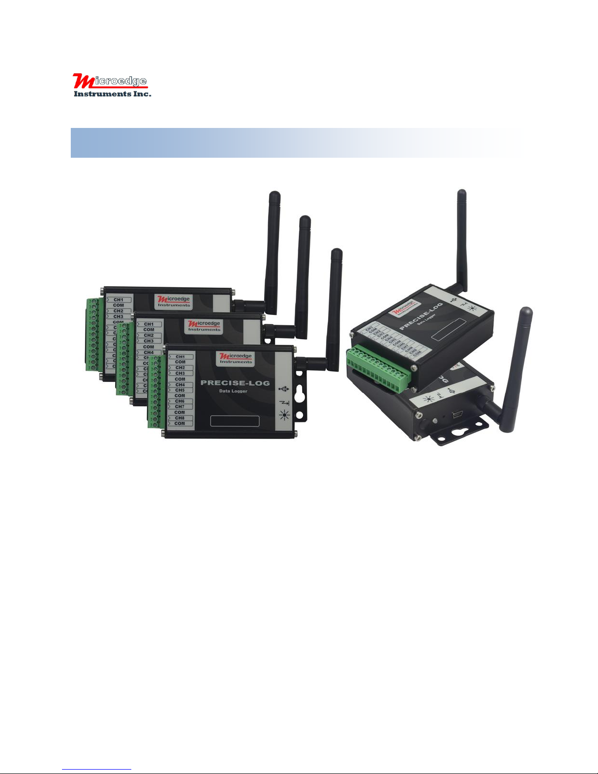
Multi-Channel Data Loggers
PRECISE-LOG
407 – 15216 North Bluff Road
White Rock, BC
Canada V4B 0A7
Phone: 604.424.9092
Toll Free: 1.877.352.9158
Fax: 1.877.453.0658
Email: [email protected]
Web: www.microedgeinstruments.com
User’s Manual
Microedge Instruments Inc.
407 – 15216 North Bluff Road
White Rock, BC, Canada, V4B 0A7
Toll Free: 1.877.352.9158
www.microedgeinstruments.com
Page 2

AAbboouutt tthhiiss MMaannuuaall
This manual contains operational information for PRECISE-LOG Data Loggers. Please read this
manual before using the data loggers.
Limits of Liability and Disclaimer of Warranty:
The manual contained in this document is furnished for informational use only and is subject to
change without notice.
Microedge Instruments Inc. shall not be liable for errors contained herein or for incidental or
consequential damages in connection with the furnishing, performance, or use of this material.
Copyright and Trademarks
This manual contains proprietary information which is protected by copyright. All rights are
reserved. No part of this document may be photocopied, reproduced, or translated to another
language without prior written consent of Microedge Instruments Inc.
Microedge Instruments Inc., PRECISE-LOG, SiteView are the trademarks of Microedge
Instruments Inc.
All other trademarks and registered trademarks are the property of their respective owners.
Microedge Instruments Inc.
407 - 15216 North Bluff Road
White Rock, BC, Canada, V4B 0A7
Toll Free: 1.877.352.9158
Web-Site: www.microedgeinstruments.com
Email: [email protected]
Rev 1.0 March. 2016
PRECISE-LOG Data Loggers User’s Manual Page 1/57
Page 3

CCoonnddiittiioonnss ooff SSaallee aanndd PPrroodduucctt WWaarrrraannttyy
Microedge Instruments Inc. (MEI) and the Buyer agree to the following terms and conditions of Sale and
Purchase:
1. Limited Warranty.
MEI warrants its product(s) to be free from defects in materials and workmanship for a period of one year from the date of
registered purchase. Any unit which is found to be defective will, at the discretion of MEI, be repaired or replaced.
MEI will not be responsible for the repair or replacement of any unit damaged by user modification, negligence, abuse,
improper installation, or mishandling.
MEI reserves the right to alter any feature or specification at any time.
2. Limitation of Liability.
The product must NOT be used in applications where failure of the product could lead to physical harm or loss of human life.
Buyer is responsible to conduct their own tests to meet the safety regulation of their respective industry.
IN NO EVENT WILL MEI BE LIABLE TO ANY PARTY FOR ANY DIRECT, INDIRECT, INCIDENTAL, SPECIAL,
CONSEQUENTIAL OR PUNITIVE DAMAGES FOR USE OF THE PRODUCT, INCLUDING, WITHOUT LIMITATION,
LOST PROFITS OR REVENUES, COSTS OF REPLACEMENT, BUSINESS INTERRUPTIONS, LOSS OF DATA OR
DAMAGES RESULTING FROM USE OF OR RELIANCE ON THE PRODUCT, EVEN IF MEI IS EXPRESSLY
ADVISED ABOUT THE POSSIBILITY OF SUCH DAMAGES.
3. Extended Warranty.
Extended 2-year warranty service is available to purchase on new products at time of order entry and up to ninety days
thereafter. The extended warranty protects you from unbudgeted service expenses and provide additional 2 years of protection
at a fraction of the price of a repair.
4. Return Policy.
Defective Product Return:
A Buyer may return a defective product to MEI for repair or replacement, at MEI option, in the event MEI determines that the
product is defective. The defective product must be returned to MEI within the warranty period. The Buyer shall be
responsible for all shipping costs. Repaired or replaced products are warranted for the balance of the original warranty period,
or at least 90 days.
Non-defective Product Return:
Products that are not defective may be returned to MEI within 30 days from the date of shipment. All non-defective product
returns are subject to a 20% restocking fee. If the product is unsatisfactory for the application for which it was purchased, MEI
shall, at its option, either refund the purchase price paid by the Buyer or replace the product with one that is satisfactory for the
application. The Buyer shall be responsible for all shipping costs and restocking fee determined by MEI.
Method of Return:
Prior to returning the product, completely fill out the RMA Application Form, send it to MEI or contact MEI directly for a
Return Material Authorization number. All products returned to MEI must be securely packaged in the original shipping
materials and reach MEI without damage and shipped in accordance with Applicable laws, rules, and regulations. The products
must contain all software and accessories that were shipped to the Buyer in connection with the product.
5. MEI reserves the right to alter any feature or specification at any time.
Notes to Buyer:
If you disagree with any of the above terms or conditions you should promptly return the unit to the
manufacturer or distributor within 30 days from date of purchase.
PRECISE-LOG Data Loggers User’s Manual Page 2/57
Page 4

TABLE OF CONTENTS
ABOUT THIS MANUAL ................................................................................................................ 1
LIMITS OF LIABILITY AND DISCLAIMER OF WARRANTY: ................................................................ 1
COPYRIGHT AND TRADEMARKS ...................................................................................................... 1
1. INTRODUCTION........................................................................................................................ 6
1.1 FEATURES OF THE LOGGER ........................................................................................................ 6
1.2 APPROVALS ............................................................................................................................... 6
1.3 CARE OF THE LOGGER ............................................................................................................... 7
1.4 IDENTITY OF THE LOGGER ......................................................................................................... 7
1.5 BATTERY ................................................................................................................................... 7
1.6 RECALIBRATION ........................................................................................................................ 8
1.7 SAFETY WARNING .................................................................................................................... 8
Maximum Input Voltage Range ................................................................................................. 8
Maximum Input Current Range ................................................................................................. 8
External Power Supply .............................................................................................................. 8
Grounding .................................................................................................................................. 8
2. HARDWARE & MECHANICAL DIMENSION ..................................................................... 9
Logger Diagram: ....................................................................................................................... 9
USB Port Pin-out (Face-In) ..................................................................................................... 10
Antenna: ................................................................................................................................... 10
3. CHANNELS AND SENSOR CONNECTIONS ...................................................................... 12
PL-V/PL-VW (WIFI ENABLED) – VOLTAGE INPUTS ................................................................... 12
Channel and Sensor Specifications: ........................................................................................ 12
PL-C/PL-CW (WIFI ENABLED) – CURRENT INPUTS..................................................................... 13
Channel and Sensor Specifications: ........................................................................................ 13
PL-T/PL-TW (WIFI ENABLED) – THERMOCOUPLE INPUTS .......................................................... 14
Channel and Sensor Specifications: ........................................................................................ 14
Measure Temperature:............................................................................................................. 15
PL-H/PL-HW (WIFI ENABLED) – THERMISTOR / RESISTOR INPUTS ............................................ 15
Channel and Sensor Specifications: ........................................................................................ 16
Measure Resistance: ................................................................................................................ 16
Measure Temperature:............................................................................................................. 16
4 BASIC FUNCTIONS .................................................................................................................. 19
BUILT-IN EQUATIONS ................................................................................................................... 19
MEASURING & LOGGING .............................................................................................................. 20
Start Time: ............................................................................................................................... 20
End Time: ................................................................................................................................. 20
Sampling Interval: ................................................................................................................... 20
Logging Mode: ......................................................................................................................... 20
DOWNLOADING DATA .................................................................................................................. 20
PRECISE-LOG Data Loggers User’s Manual Page 3/57
Page 5

FIELD ACTIVATION ....................................................................................................................... 20
RESET DEVICE .............................................................................................................................. 22
STATUS LED................................................................................................................................. 22
5. SOFTWARE ............................................................................................................................... 23
SYSTEM REQUIREMENTS ............................................................................................................... 23
COMMUNICATIONS INTERFACES ................................................................................................... 23
INSTALL SITEVIEW AND USB DRIVER .......................................................................................... 24
CONNECT DATA LOGGER .............................................................................................................. 29
ACTIVATE SITEVIEW .................................................................................................................... 32
MAIN WINDOW FRAME ................................................................................................................. 34
Communication Panel .............................................................................................................. 34
Menu Bar ................................................................................................................................. 34
Tool Bar ................................................................................................................................... 34
Main Working Panel ................................................................................................................ 35
Information Log Panel ............................................................................................................. 35
VIEW LOGGER STATUS ................................................................................................................. 35
General .................................................................................................................................... 36
Alarm........................................................................................................................................ 36
CONFIGURE LOGGER ..................................................................................................................... 38
Description: ............................................................................................................................. 39
Sampling Interval: ................................................................................................................... 39
On-Board LED ......................................................................................................................... 40
When Memory Full .................................................................................................................. 40
Time to Start & Time to End .................................................................................................... 40
Total Time Span ....................................................................................................................... 40
Enabled .................................................................................................................................... 40
Channel Range ......................................................................................................................... 41
Description ............................................................................................................................... 41
Equation ................................................................................................................................... 41
Cali. Low & Cali. High ............................................................................................................ 41
DOWNLOAD LOGGER .................................................................................................................... 43
Filename & Browse ................................................................................................................. 45
Start Time & End Time ............................................................................................................ 45
REAL-TIME DISPLAY .................................................................................................................... 46
List View Visible ...................................................................................................................... 48
Chart View Visible ................................................................................................................... 48
Vertical View ............................................................................................................................ 48
Horizontal View ....................................................................................................................... 48
Time Span................................................................................................................................. 48
Dataset ..................................................................................................................................... 49
Settings ..................................................................................................................................... 49
CALIBRATE A CHANNEL ................................................................................................................ 50
Understand Cali. Low & Cali. High ........................................................................................ 50
Decide On-Line or Off-Line Calibration ................................................................................. 51
COMMUNICATE WITH PRECISE-LOG WIRELESSLY .................................................................... 54
PRECISE-LOG Data Loggers User’s Manual Page 4/57
Page 6

6. SPECIFICATIONS.................................................................................................................... 56
COMMON SPECIFICATIONS ............................................................................................................ 56
LOGGING CAPACITY ..................................................................................................................... 57
PRECISE-LOG Data Loggers User’s Manual Page 5/57
Page 7
11.. IInnttrroodduuccttiioonn
1.1 Features of the logger
Congratulations on purchasing the PRECISE-LOG series data loggers! These portable battery
powered data loggers allow recording information and saving measurements to a 8MB flash
memory for later retrieval.
The internal lithium battery provides up to 10 years of instantaneous logging operation when
sampling at interval of one minute in stand-alone mode.
PRECISE-LOG data logger can be manipulated by SiteView Windows software for data
downloading, logging management, and property configuration. It has USB interface for local
communications and a WIFI module for remote access (PL-[x]W Series).
PRECISE-LOG data logger features a wide sampling interval range from one second to 12
hours.
The 16-bit analog-to-digital converter makes the measurements more precise and accurate.
Rugged, splash resistant aluminum enclosure makes it excellent in the harshest industrial
environment.
WIFI enabled version allows remote data monitoring and downloading.
1.2 Approvals
All PRECISE-LOG Series data loggers are in conformity with the EN standard(s) listed below:
EN 61000-6-1:[2007]
EN61000-4-2:2009
EN61000-4-3:2006/A2:2010
EN61000-4-4:2012
EN61000-4-5:2006
EN61000-4-6:2014
EN61000-4-11:2004
EN 61000-6-3:[2007]
EN Standards for WIFI module:
PRECISE-LOG Data Loggers User’s Manual Page 6/57
Page 8
EN62311:2008
EN60950-1:2006+A11:2009+A1:2010+A12:2011+A2:2013
ETSI EN300 328 V1.8.1 (2012-06)
ETSI EN 301 489-1 V1.9.2 (2011-09)
ETSI EN 301 489-17 V2.2.1 (2012-09)
For WIFI enabled models:
Contains FCC ID:2ACZO-WIFI1232T
All PRECISE-LOG Series data loggers comply with Part15 of the FCC Rules. Operation is
subject to the following two conditions:
1. These devices may not cause harmful interference, and
2. These devices must accept any interference received, including interference that may cause
undesired operation.
1.3 Care of the logger
PRECISE-LOG data loggers are designed to work in humid atmospheres of up to 95% RH noncondensing. They should be protected against immersion. The environment temperature should
be within – 40 to +70°C (-40 to + 158°F).
1.4 Identity of the logger
Each logger has its own unique serial number, which can be found on the back of the enclosure.
The serial number is used to identify the logger and enable us to keep a record of its history like
calibrations and warranty. Please reference it in any correspondence with MEI.
1.5 Battery
The battery lasts in excess of 10 years when sampling at 1-minute intervals in stand-alone
mode. When the battery is nearing the end of its service life, the on-board status LED will glow
in amber each time the logger is sampling the data. The battery indicator on the status window
in SiteView software will also display warning of low battery level. The battery operates
approximately one or two weeks from the time the logger first indicates a low battery, but we
recommend that the battery be changed as soon as the warning is displayed. The battery is
factory replaceable only.
PRECISE-LOG Data Loggers User’s Manual Page 7/57
Page 9

1.6 Recalibration
Any PRECISE-LOG data logger is supplied with all channels pre-calibrated and should not
require any further recalibration for a period of 12 months.
We recommend the logger be recalibrated every year. You may recalibrate the logger longer
than a year depending on your application standard.
You may return the logger to the supplier for recalibration service or recalibrate it on your own
via SiteView software.
SiteView software provides two-point calibration for the most of the loggers.
1.7 Safety Warning
Maximum Input Voltage Range
For logger model: PL-V, PL-VW (WIFI enabled):
The logger is designed to measure single common ground DC voltages in the range up to 20
VDC. Any voltages over this range may cause permanent damage to the device.
Maximum Input Current Range
For logger model: PL-C, PL-CW (WIFI enabled):
The logger is designed to measure single common ground DC current in the range up to 50
mA. Any current over this range may cause permanent damage to the device.
External Power Supply
When using external power supply (via PC’s USB port or thirty party +5 VDC power
supply) to power the logger please make sure that the external power supply has the same
common ground with the external input process signals.
When using other third party external power supplies, please make sure the voltage of the
external power supply is +5 VDC (+/- 5% ripple).
Grounding
The common ground of the PRECISE-LOG data logger is connected directly to the ground
of the input process signals and the ground of the external power supply (if applicable).
PRECISE-LOG Data Loggers User’s Manual Page 8/57
Page 10
22.. HHaarrddwwaarree && MMeecchhaanniiccaall DDiimmeennssiioonn
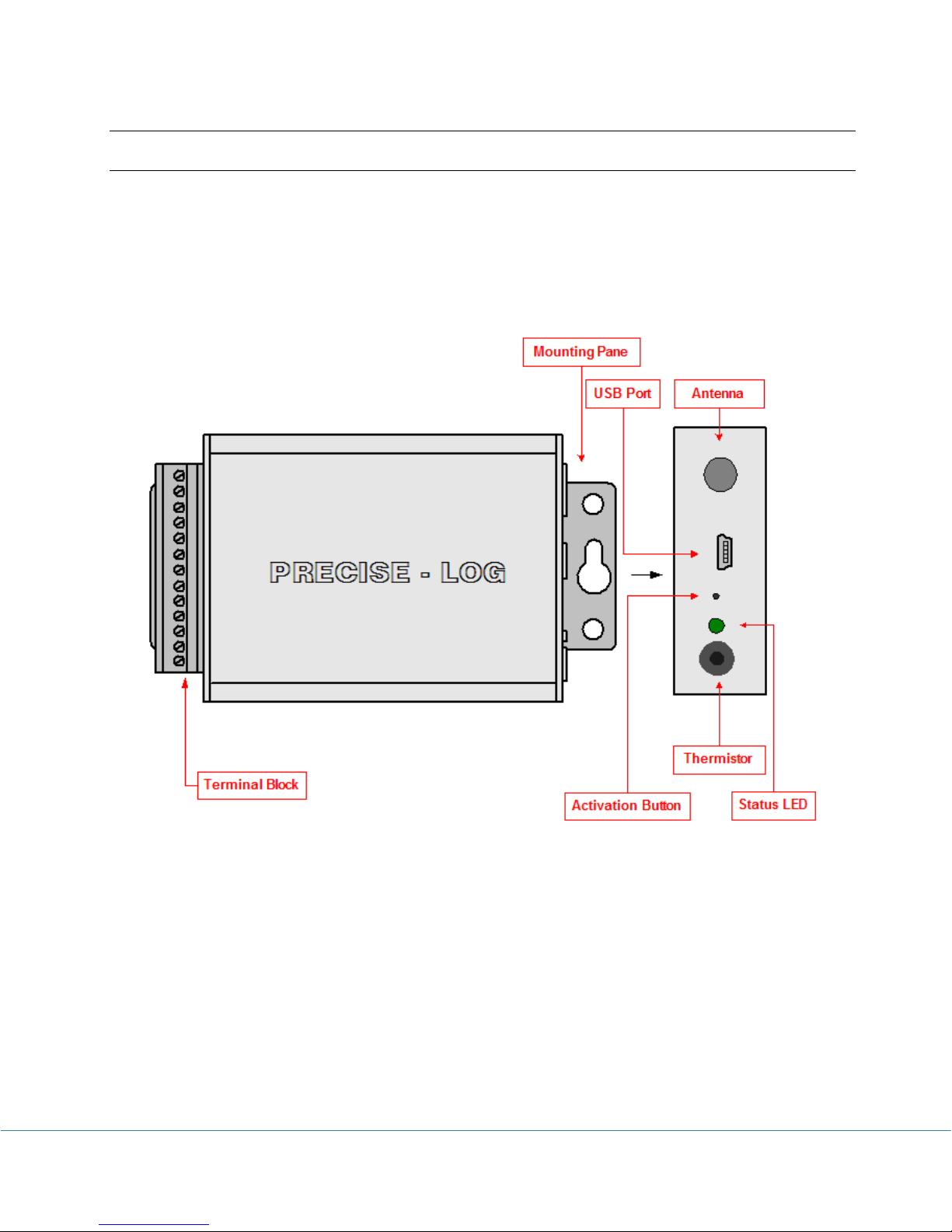
Logger Diagram:
For Model PL-V, PL-VW (WIFI enabled), PL-C, PL-CW (WIFI enabled), PL-T, PL-TW
(WIFI enabled), PL-H, PL-HW (WIFI enabled)
PRECISE-LOG Data Loggers User’s Manual Page 9/57
Page 11
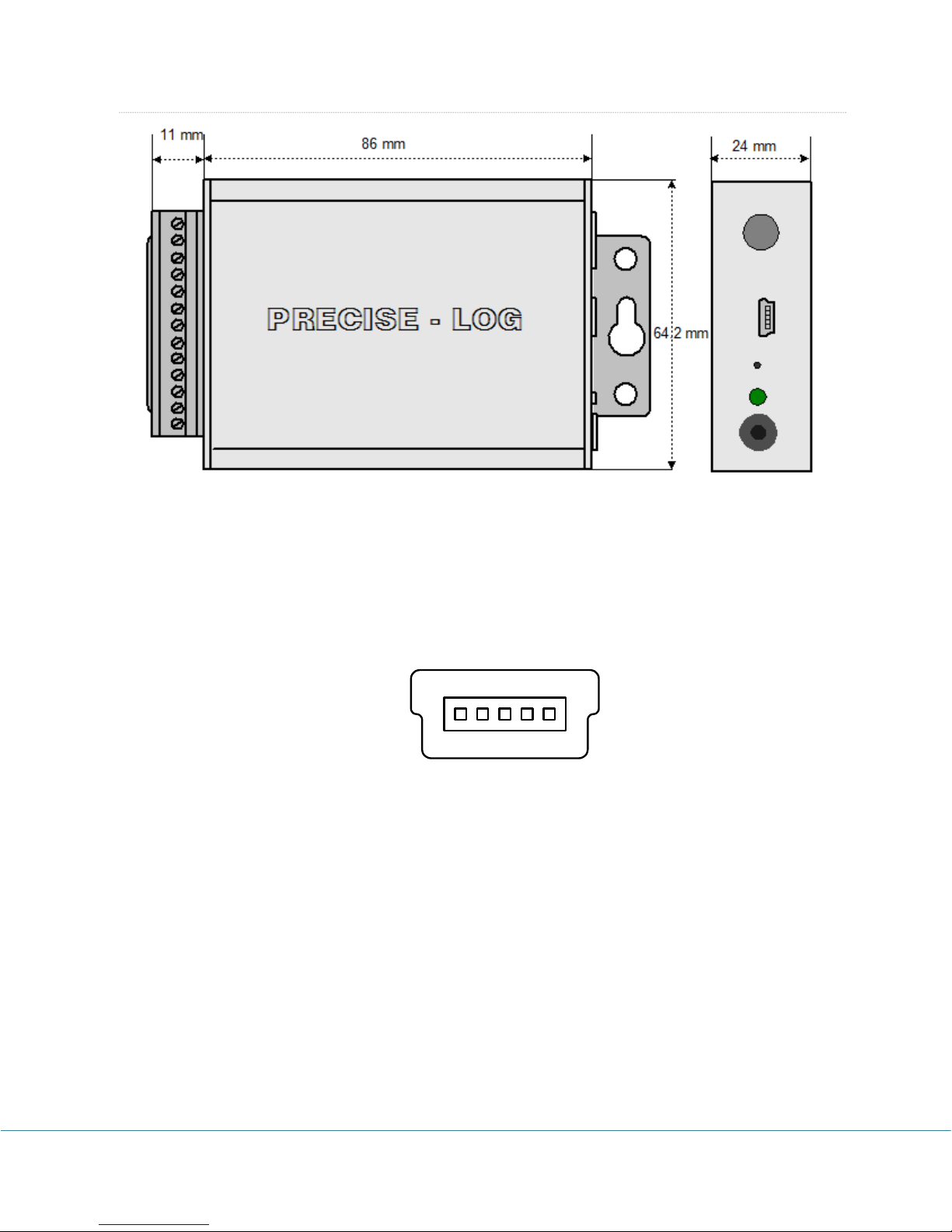
Dimension: 88 X 64.2 X 24 MM
1
5
432
3.46 X 2.53 X 0.95 Inches
USB Port Pin-out (Face-In)
Pin1: External Power Supply (+5 VDC)
Pin2: Logger Communications Receiver Line (RX)
Pin3: Logger Communications Transmitter Line (TX)
Pin4: Common Ground (COM , GND)
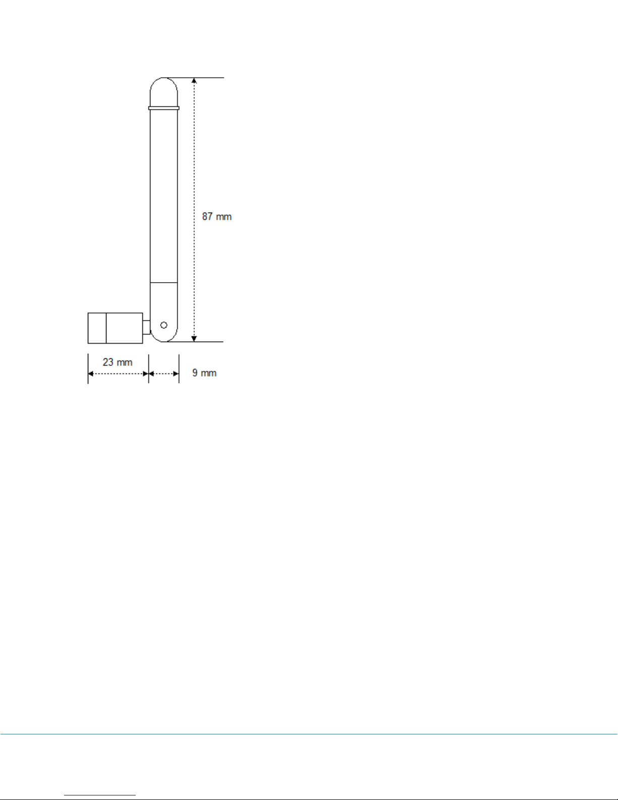
Antenna:
PRECISE-LOG Data Loggers User’s Manual Page 10/57
Page 12
PRECISE-LOG Data Loggers User’s Manual Page 11/57
Page 13
33.. CChhaannnneellss aanndd SSeennssoorr ccoonnnneeccttiioonnss
Connections:
Pluggable terminal block for eight external channels
Channels:
CH1 to CH8: Eight external Voltage DC with software
programmable input range selections for each channel:
0 to 20 V, 0 to 5 V
Resolution:
0.0018%
Accuracy:
+/- 0.05% FSR @ 25°C
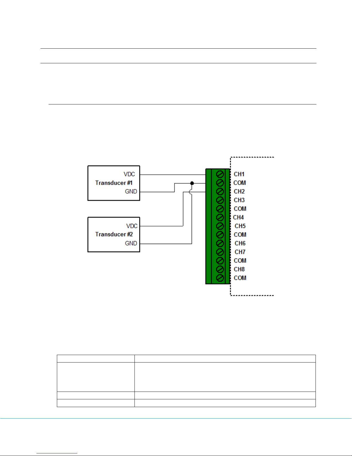
All “COM” terminals are connected together and should be connected to the common ground of
the process signals.
PL-V/PL-VW (WIFI enabled) – Voltage Inputs
A PL-V or PL-VW (WIFI enabled) logger has eight external voltage DC channels used to
measure single-ended voltage DC signals maximum of 20 volt. The following figure illustrates
the correct input connections:
Voltage External Input Connections
Note: All inputs must share the same common ground.
Channel and Sensor Specifications:
PRECISE-LOG Data Loggers User’s Manual Page 12/57
Page 14
Input Impedance:
> 1 Mohms
Over-voltage protection:
+/- 40 VDC
Connections:
Pluggable terminal block for eight external channels
Channels:
CH1 to CH8: Eight external current DC with software
programmable input range selections for each channel:
4-20 mA, 50 mA
ADC Resolution:
0.0018%
Accuracy:
+/- 0.1% FSR @ 25°C
Load Resistance:
12 Ohm
Over-current Protection
+/- 100 mA
PL-C/PL-CW (WIFI enabled) – Current Inputs
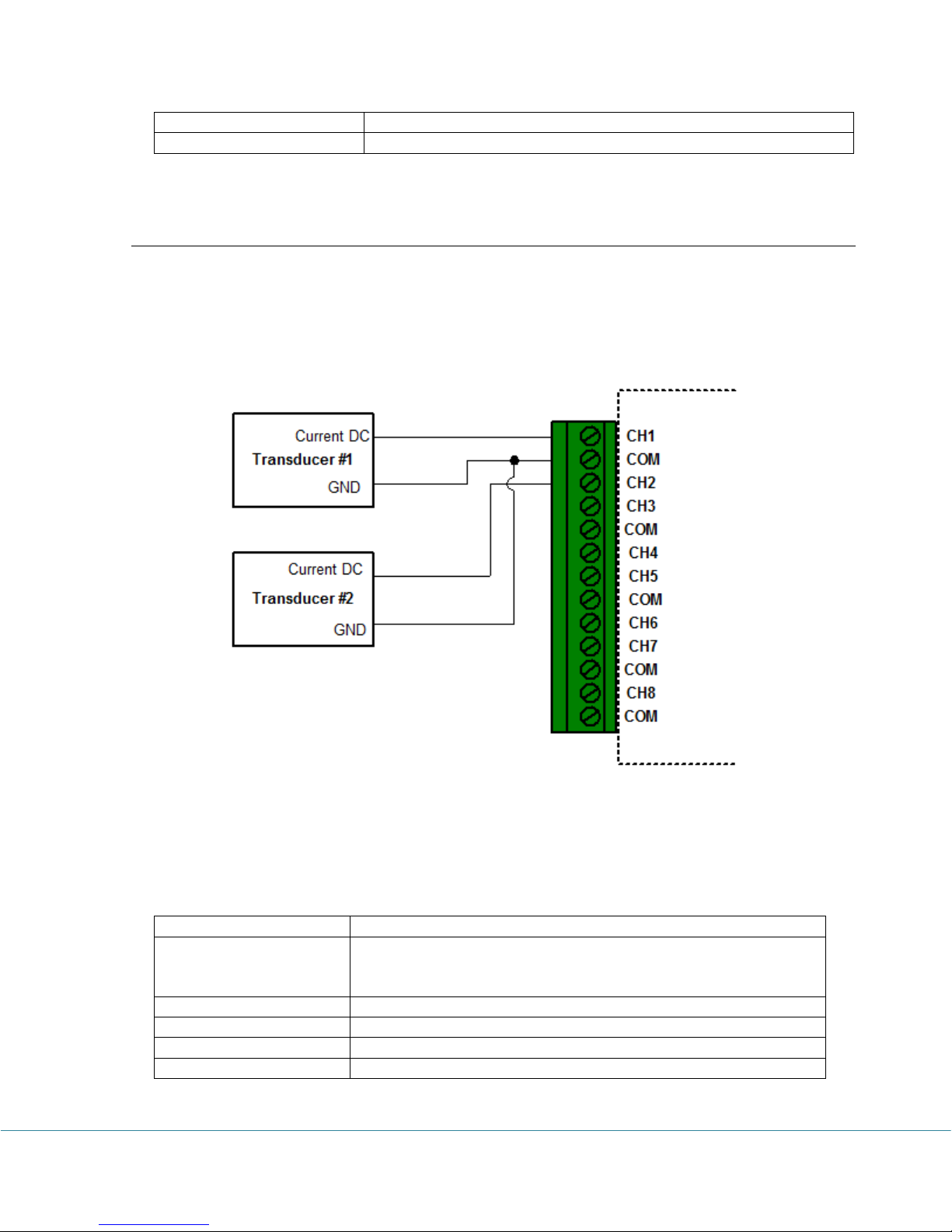
A PL-C or PL-CW (WIFI enabled) logger has eight external current DC channels used to
measure single-ended current DC signals maximum of 50 mA. The following figure illustrates
the correct input connections:
Current External Input Connections
Note: All inputs must share the same common ground.
Channel and Sensor Specifications:
PRECISE-LOG Data Loggers User’s Manual Page 13/57
Page 15
PL-T/PL-TW (WIFI enabled) – Thermocouple Inputs
Connections:
Plugeable terminal block for eight external channels
Channels:
CH0: on-board thermistor (-40 ~ +70°C) (-40 to + 158°F).
CH1 to CH8: Eight external Voltage DC with software
programmable input range selections for each channel:
Range1: -8 to +73 mV
Range3: -2 to +18 mV
Resolution:
0.0018%
Accuracy:
Thermistor channel: +/- 0.2°C(0°C ~ 70°C)
Voltage channels:
Range:(-8 to +73 mV:
+/- 0.1% (0.08 mV) @ 25°C + T/C Accuracy
Range -2 to +18 mV:
+/- 0.15% (0.03 mV) @ 25°C + T/C Accuracy
Over-voltage protection:
+/- 20 VDC
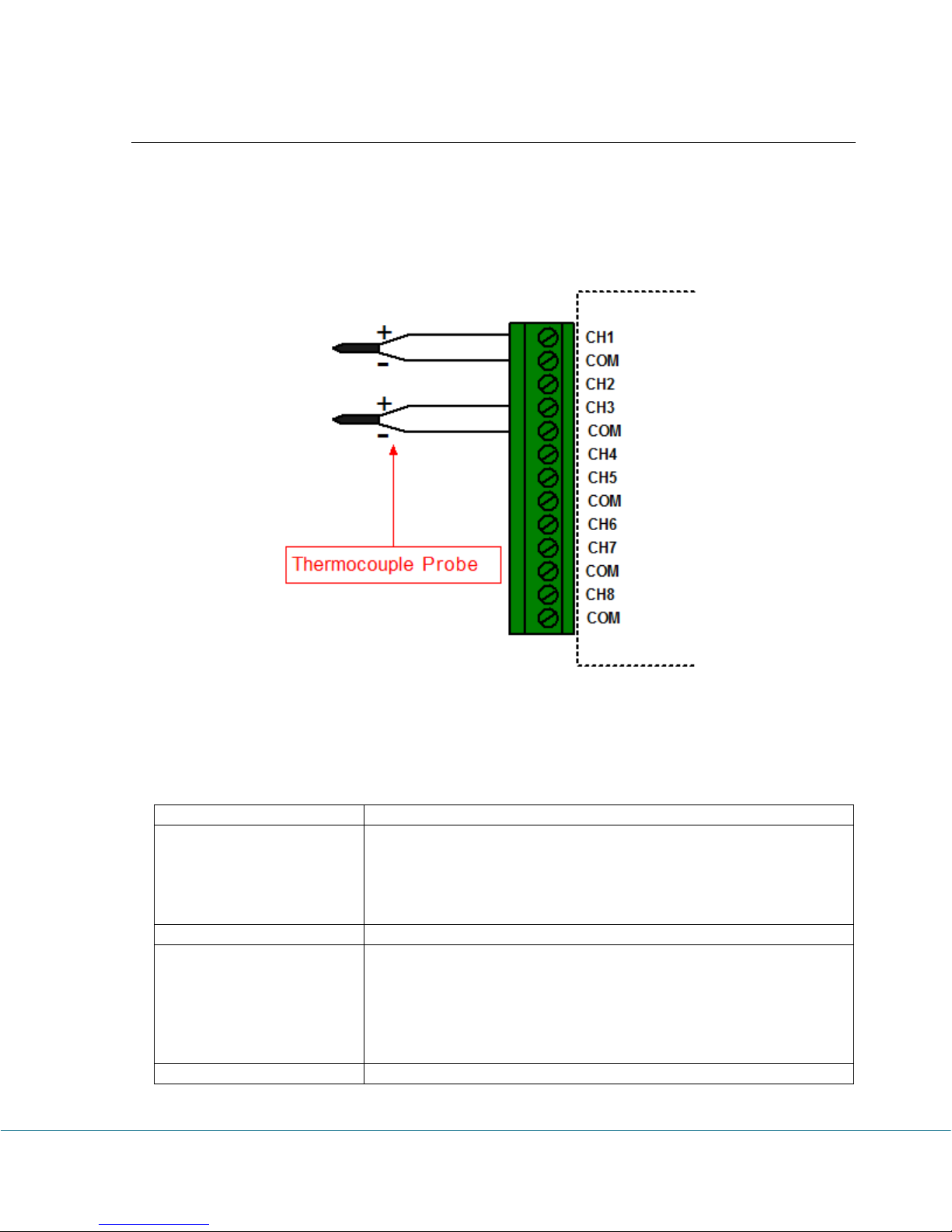
Besides the on-board thermistor channel, PL-T/PL-TW (WIFI enabled) logger has eight
external voltage DC channels used to measure thermocouple probes or small voltage signals.
The following figure illustrates the correct input connections:
Thermocouple Input Connections
Note: All inputs must share the same common ground.
Channel and Sensor Specifications:
PRECISE-LOG Data Loggers User’s Manual Page 14/57
Page 16
Measure Temperature:
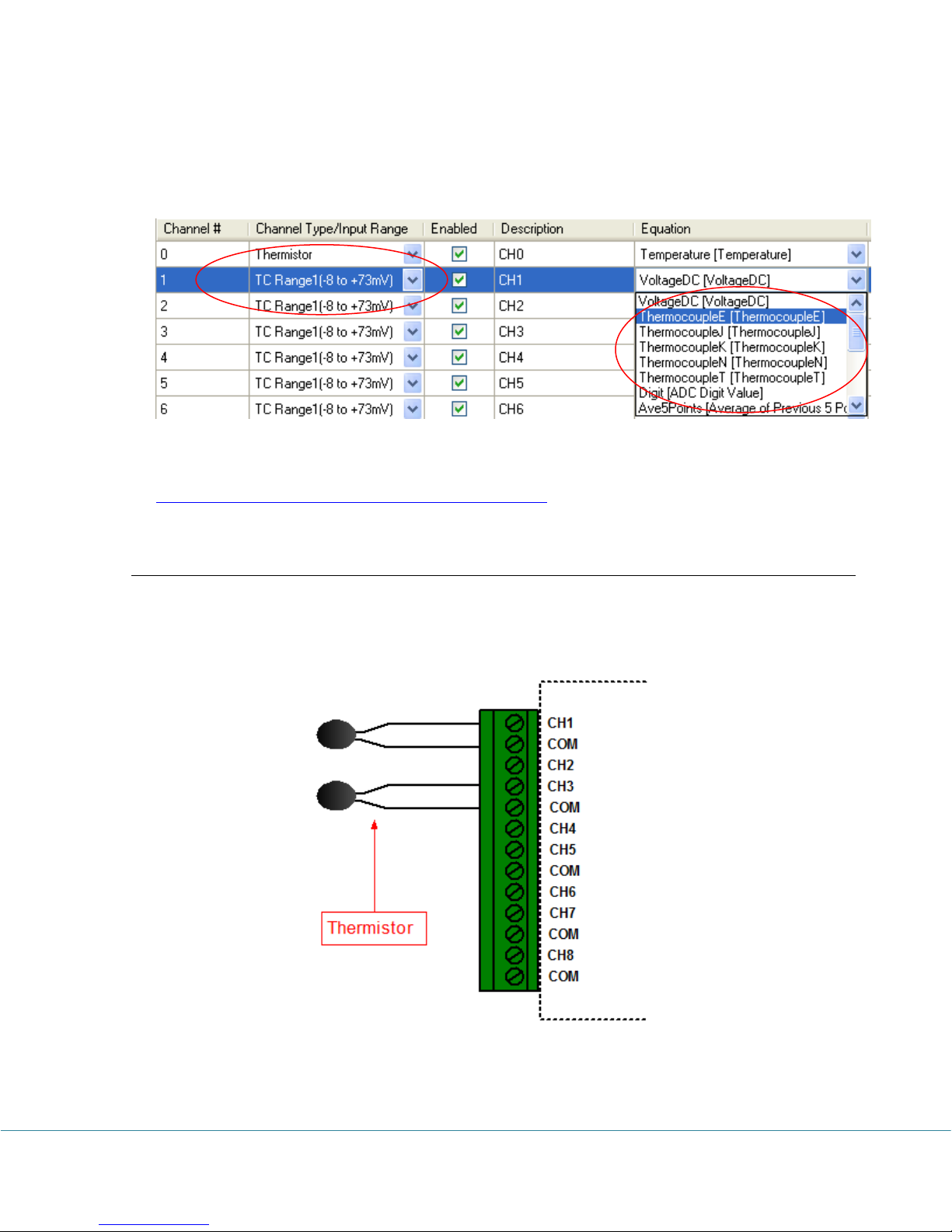
Based on the thermocouple type you want to use and the desired temperature range you want
to measure you can select one of four channel’s available ranges and the correct factory
thermocouple equation:
For detailed temperature range and voltage – temperature look-up table of a specific
thermocouple type please refer to NIST’s website at:
http://srdata.nist.gov/its90/download/download.html
PL-H/PL-HW (WIFI enabled) – Thermistor / Resistor Inputs
PL-H/PL-HW (WIFI enabled) logger has eight external channels used to measure the external
thermistors or resistors. The following figure illustrates the correct input connections:
Thermistor External Input Connections
PRECISE-LOG Data Loggers User’s Manual Page 15/57
Page 17
Note: All inputs must share the same common ground.
Connections:
Plugeable terminal block for eight external channels
Channels:
CH1 to CH8: Eight external thermistor
Resolution:
0.0018%
Accuracy:
Thermistor channel: +/- 0.2°C(0°C ~ 70°C)
External channels:
+/- 0.2% FSR @ 25°C
Channel and Sensor Specifications:
Measure Resistance:
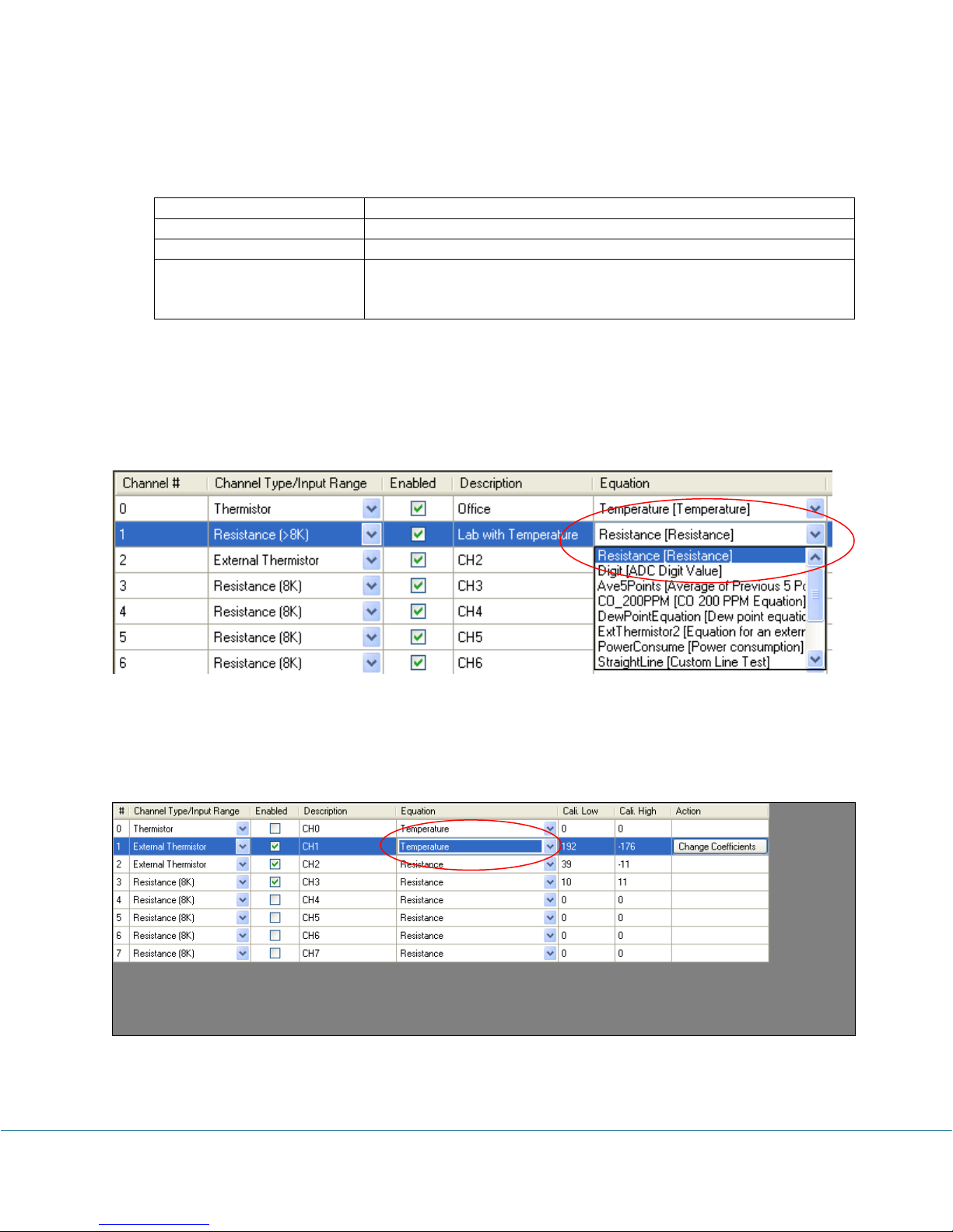
SiteView provides factory resistance equation for measuring the resistor’s value. In
Configuration dialog:
Choose Resistance equation:
Measure Temperature:
The simple way to measure temperature is by using built-in “Temperature” equation. You
select “Temperature” in “Equation” column:
Then you need to change temperature coefficient values by clicking “Change Coefficients”
button in “Action” column:
PRECISE-LOG Data Loggers User’s Manual Page 16/57
Page 18
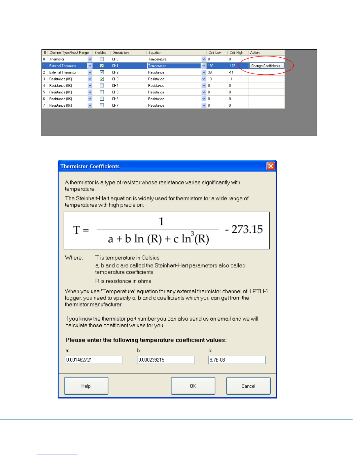
In the pop-up dialog enter new temperature coefficient values and click “OK” button.
PRECISE-LOG Data Loggers User’s Manual Page 17/57
Page 19
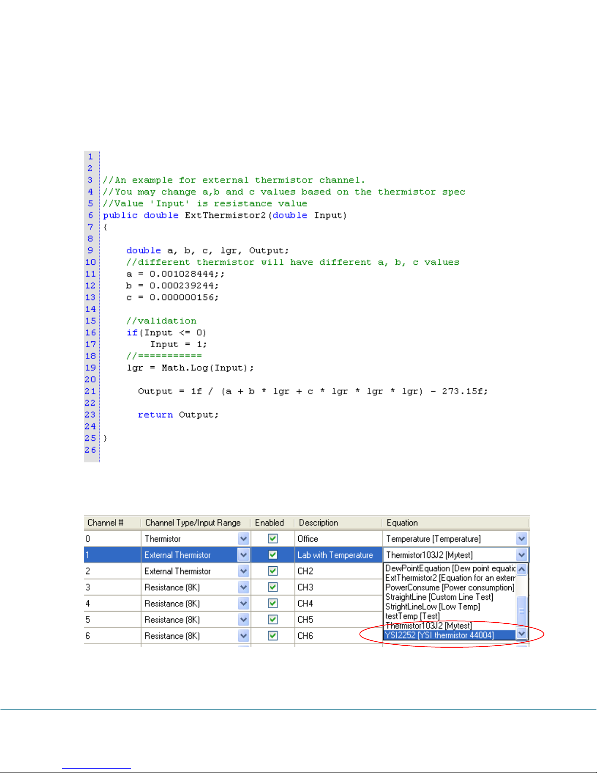
You can also use a custom equation to do the same job or even more complicated
calculation. An example of external thermistor equation is included in SiteView package.
When you create your own equation you can refer to this equation and replace those
temperature coefficients with the ones obtained from the thermistor manufacturer. The
contents of the sample equation looks like this:
Once you have created your equation (for example YSI2252(YSI thermistor 44004)), you can
apply it to the channel:
PRECISE-LOG Data Loggers User’s Manual Page 18/57
Page 20
44 BBaassiicc FFuunnccttiioonnss
Channel Type
Equation Name
Equation Description
Internal-Thermistor
Temperature
Temperature
External-Thermistor
Temperature
Temperature
0-5 VDC
VoltageDC
Voltage DC
0-20 VDC
VoltageDC
Voltage DC
4-20 mA DC
CurrentDC
Current DC
0-50 mA DC
CurrentDC
Current DC
Thermocouple
Range:
-8 to +73 mV
ThermocoupleE
ThermocoupleJ
ThermocoupleK
ThermocoupleN
ThermocoupleT
VoltageDC
Thermocouple E
Thermocouple J
Thermocouple K
Thermocouple N
Thermocouple T
Voltage DC
Thermocouple
Range:
-2 to +18 mV
ThermocoupleB
ThermocoupleE
ThermocoupleJ
ThermocoupleK
ThermocoupleN
ThermocoupleR
ThermocoupleS
ThermocoupleT
VoltageDC
Thermocouple B
Thermocouple E
Thermocouple J
Thermocouple K
Thermocouple N
Thermocouple R
Thermocouple S
Thermocouple T
Voltage DC
X
InternalBattery
Measure the internal battery
voltage level
X
ExternalPower
Measure the external power
supply
Built-In Equations
Equation and Channel Type are two essential parameters to make sure the physical
measurement can be converted correctly.
An equation is a software functionality identified by its name of up to 16 characters. A built-in
equation is an equation provided by SiteView software to convert a measurement for a specific
channel type.
A channel must have an equation assigned to it in order to make the measurement conversion.
“Digit” built-in equation can be assigned to any channel type. If you assign “Digit” equation to
a channel the physical measurement will be the original digital value measured by ADC
(Analog-to-digital converter) hardware.
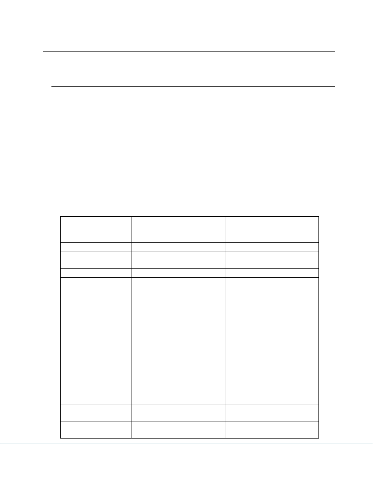
The following table lists all available built-in equations for all channel types:
PRECISE-LOG Data Loggers User’s Manual Page 19/57
Page 21

Measuring & Logging
During the session of logging, when it’s time to sample, the PRECISE-LOG measures the
signal of each enabled channel, converts it to digital value and saves to the on-board memory.
The PRECISE-LOG uses a group of pre-set parameters to decide when and how to take in data
and save it to the memory. Those parameters can be configured by SiteView software and their
definitions are given as below:
Start Time:
This parameter specifies the date and time when the logger starts the session of logging.
End Time:
This parameter specifies the date and time when the logger will stop the session of logging.
This value may be overridden by Logging Mode parameter. . If Logging Mode was set to
Continue Logging, the Start Time and the End Time will be shifted forward.
Sampling Interval:
This parameter specifies the time span the logger will wait after it takes the first sample and
before it takes the second sample.
Logging Mode:
This parameter specifies if the logger will stop or continue logging when the memory is full.
Available settings are Stop Logging and Continue Logging.
If Logging Mode was set to Stop Logging, the logger will stop logging at the End Time. If
Logging Mode was set to Continue Logging, the logger will continue logging and the
oldest data will be overwritten by the new data.
Downloading Data
The data in the logger can be transferred to the computer by SiteView software even when the
logger is still recording
The readings saved in the logger are ADC digital values, and will be converted to physical
measurements by SiteView software after they are downloaded to the computer. The data
conversion is handled by an equation that may be embedded in SiteView software or a script
provided by the user.
Field Activation
PRECISE-LOG data logger comes with an on-board activation button which can be used to
activate/initiate the logging session in the field.
PRECISE-LOG Data Loggers User’s Manual Page 20/57
Page 22
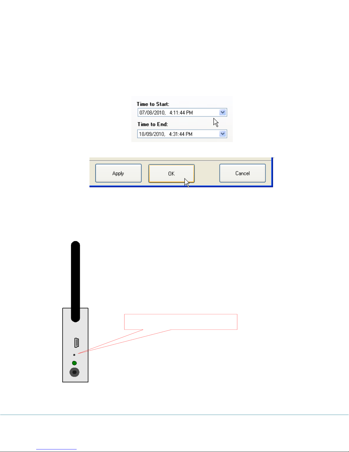
Push to activate new logging session
To activate the logger for new session:
1. With the SiteView software, open the configuration dialog of the logger, and set the start
time to any time the desired start time will never reaches. Click OK button to save new
settings to the logger.
2. The logger is now in Start Delay mode. When you need to activate the logger, press and
hold the Activation button on the logger. When you see the status LED starts to flash
release the button. The logger is now activated and is recording data.
PRECISE-LOG Data Loggers User’s Manual Page 21/57
Field Activation
Page 23

Note: The activation button cannot be further activated once the logger has started the new
session.
Reset Device
The on-board activation button can also be used as a reset button in case the data logger does
not respond to the PC communications.
Reset of CPU will cause the data and clock losses. Please reconfigure the logger after the
recovery.
To reset the CPU, press and hold the activation button, the LED starts to blink in RED color
with interval of one second. After 10 seconds the LED starts quick blinking to indicate it will
reset the CPU. Release the button when you see this. Then plug the logger to USB port of PC,
Site View should show it under the USB comm Tab.
Status LED
PRECISE-LOG logger has an on-board LED used to indicate:
1. Sampling:
When the LED was enabled by SiteView, it will flash once in green when the logger is
sampling. The colour of the LED can be overridden by the following conditions:
2. Alarms:
The LED will flash in red when it samples if any channel alarms are enabled and are
triggered.
3. Low Battery:
The LED will flash in amber when it samples if the logger detects a low battery level.
If you do not need the LED to indicate the status of operation you can disable it (via SiteView)
in order to increase the battery life.
PRECISE-LOG Data Loggers User’s Manual Page 22/57
Page 24
55.. SSooffttwwaarree
SiteView Windows software is used to communicate with the PRECISE-LOG data logger for data
downloading, logging management, and channel range configuration.
This section outlines basic functions that SiteView offers. For complete instructions on how to use
SiteView software please refer to SiteView User’s Manual available for download online.
System Requirements
Computer:
CPU: 1.0 GHZ or above
Memory: 1 GB or above
Port: 1 USB port
Hard Drive: 1GB or above
Operating System:
Window XP with SP2 or above, Window Vista, Window 7, 8, 10
Communications Interfaces
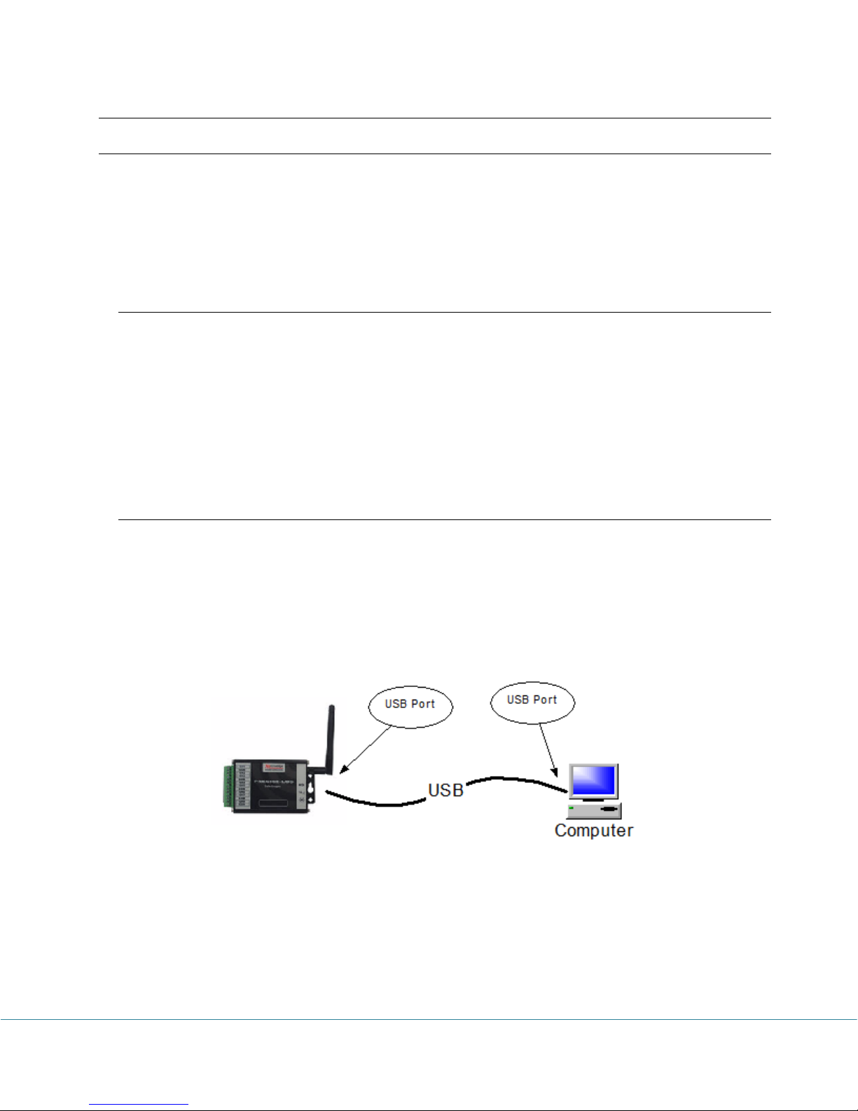
The PRECISE-LOG logger has a USB port used for communications with a computer. The
WIFI enabled version has an on-board WIFI module used for remote communication.
The following schematics illustrate different options that SiteView software can communicate
with a data logger.
PRECISE-LOG Data Loggers User’s Manual Page 23/57
USB Connection
Page 25
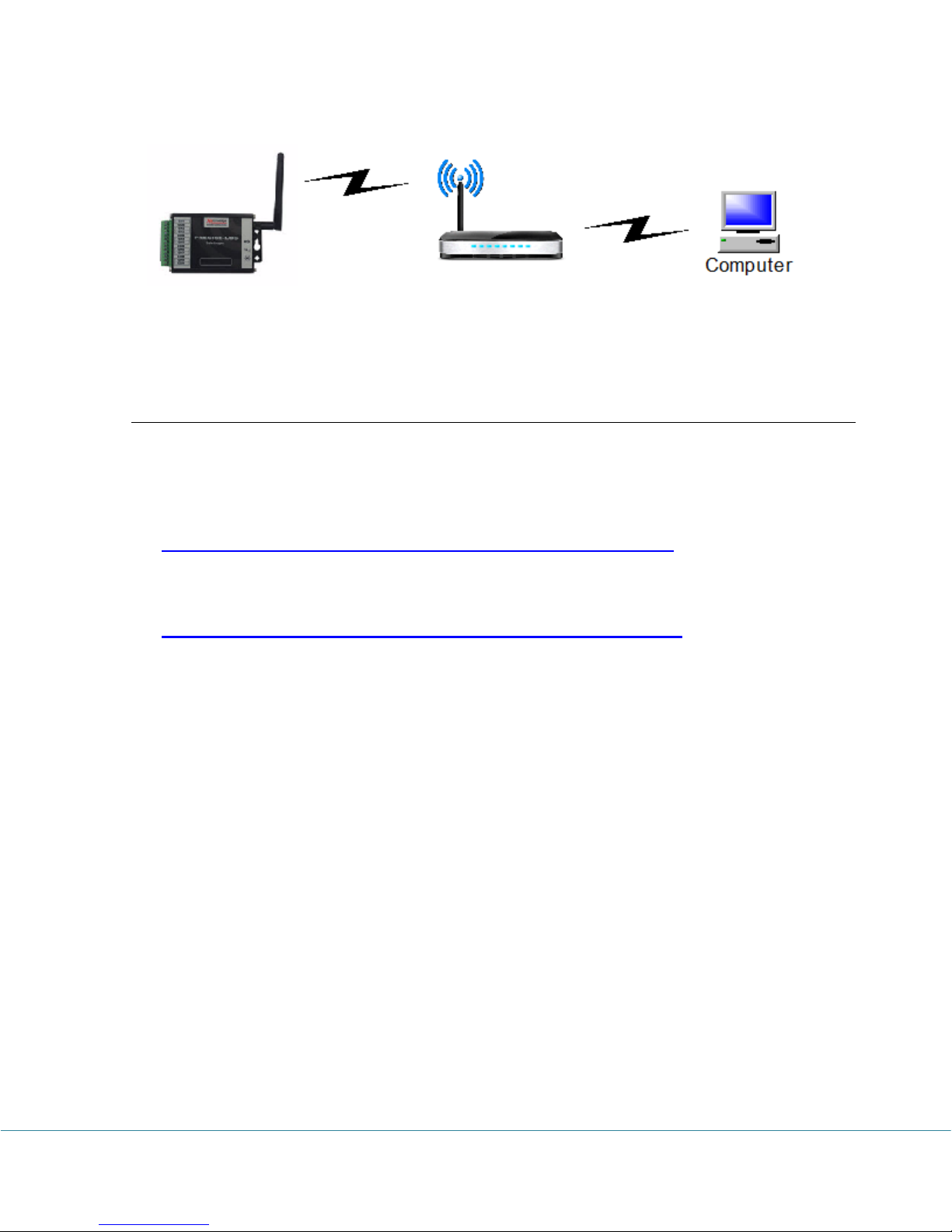
WIFI Wireless Connection
Install SiteView and USB Driver
1. Configure for Windows 8,10 User:
Please refer to the on-line document about how to configure Windows 8 for the USB
driver to be installed correctly:
http://www.microedgeinstruments.com/Win8Configurations.pdf
Please refer to the on-line document about how to configure Windows 10 for the USB
driver to be installed correctly:
http://www.microedgeinstruments.com/Win10Configurations.pdf
2. Install SiteView.
Insert the included CD to the CD Drive. The installation should start to run automatically.
Follow the on-screen instructions to complete the installation.
PRECISE-LOG Data Loggers User’s Manual Page 24/57
Page 26
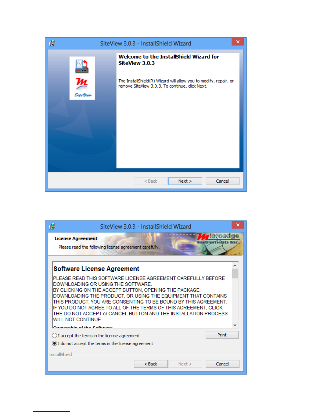
Click “Next >” button to proceed to the next page.
PRECISE-LOG Data Loggers User’s Manual Page 25/57
Page 27
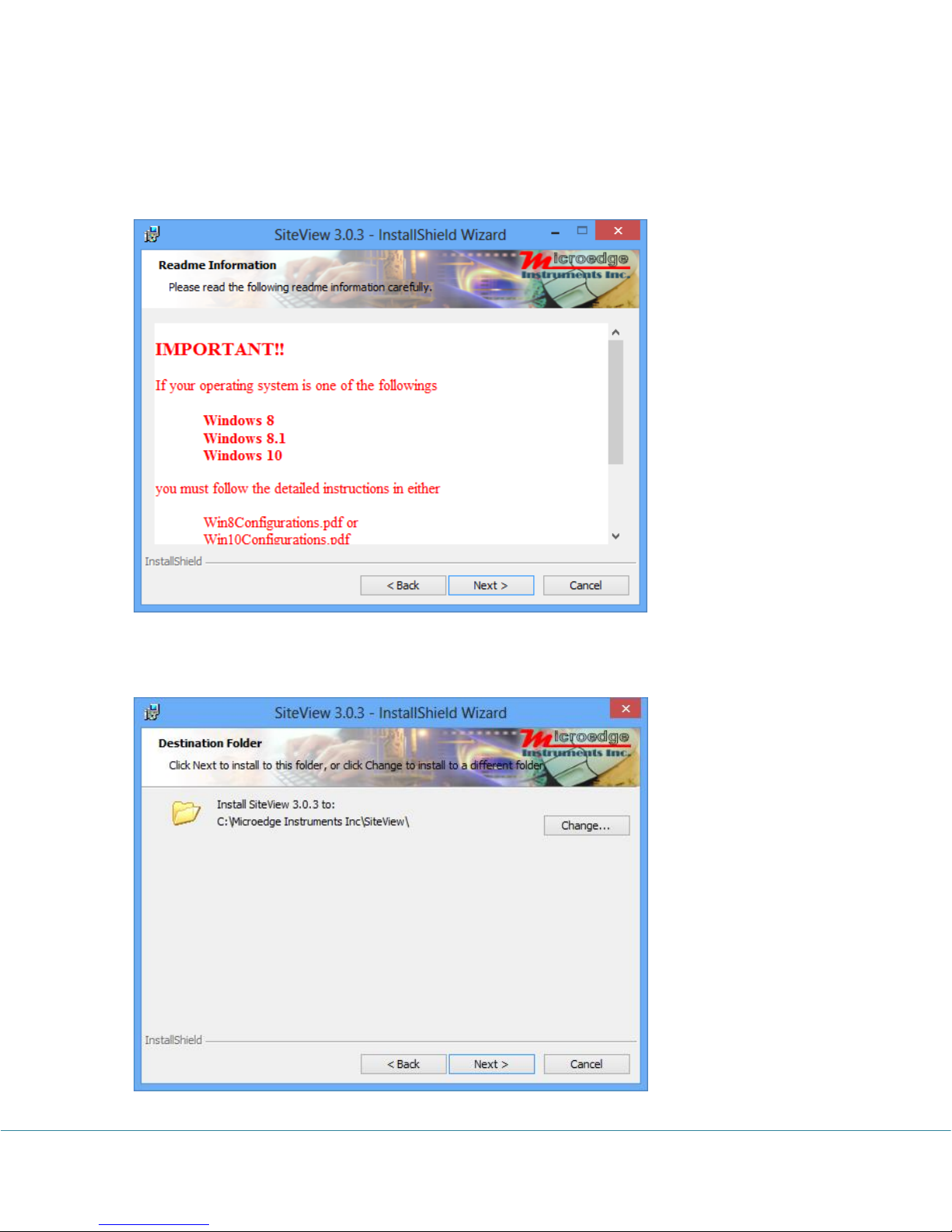
Please read the License Agreement carefully. If you accept the terms click “I Agree”, then click
“Next >” button. Otherwise click “Cancel” to cancel the installation.
If you have already followed the Windows 8/10 instructions click “Next >” button to proceed to
the next page.
PRECISE-LOG Data Loggers User’s Manual Page 26/57
Page 28
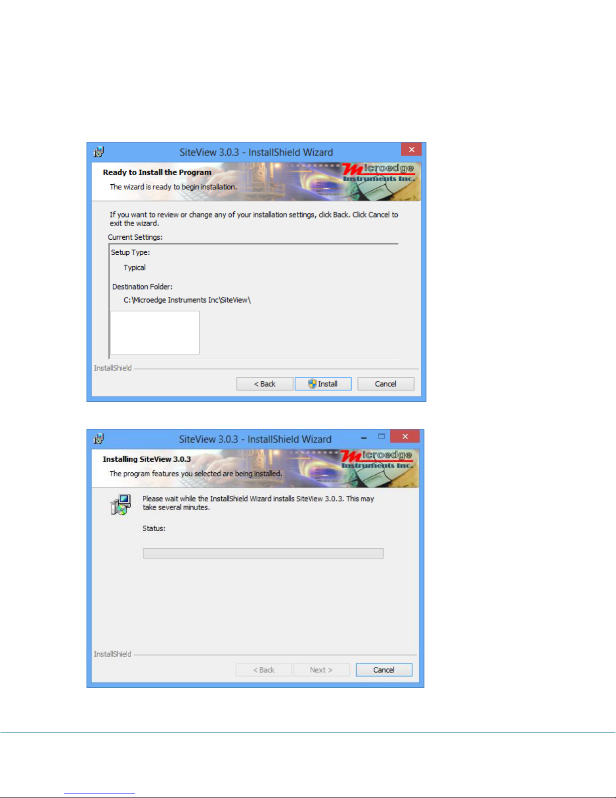
In this dialog select a destination folder where SiteView will be installed. We recommend you
keep the default folder.
Once you are ready, click “Next >” button to proceed to the next page.
Click “Install” button to start the installation.
PRECISE-LOG Data Loggers User’s Manual Page 27/57
Page 29
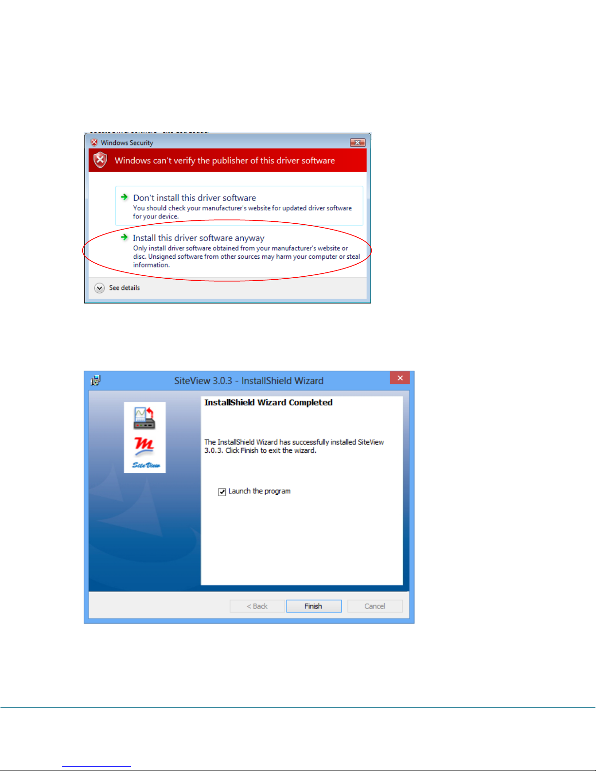
Depending on the operating system, you may see the dialog similar to the one below displayed.
Please select “Continue Anyway” or “Install this driver software anyway” to allow the
software and the driver to be installed.
As SiteView is being installed the above dialog shows the installation progress by percentage.
Once the installation is complete, the below dialog appears:
Click “Finish” button to finish the installation and close the dialog.
PRECISE-LOG Data Loggers User’s Manual Page 28/57
Page 30
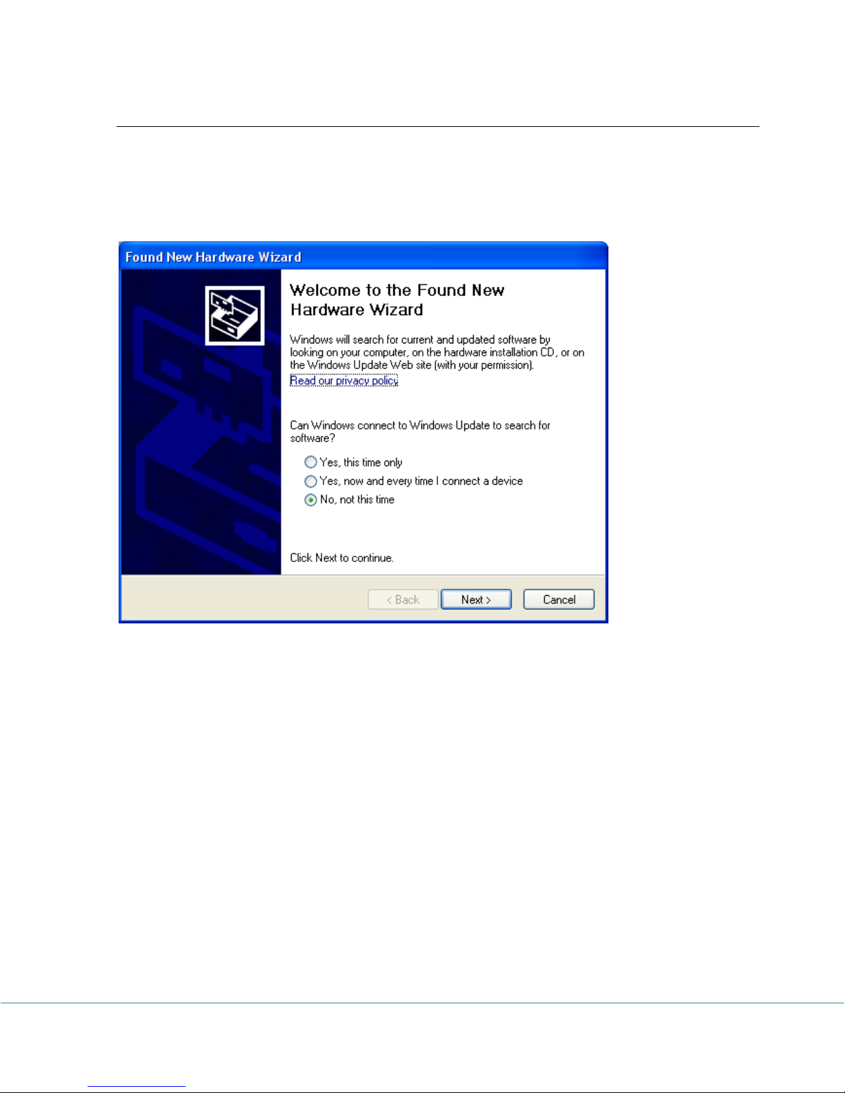
Connect Data Logger
Connect the logger to the computer’s USB port. Windows Vista and Windows 7, 8, 10 will
automatically recognize the data logger.
For Windows XP user, the following dialog window will appear:
Select "No, not this time" from options available and then Click "Next >" to proceed with the
installation.
PRECISE-LOG Data Loggers User’s Manual Page 29/57
Page 31
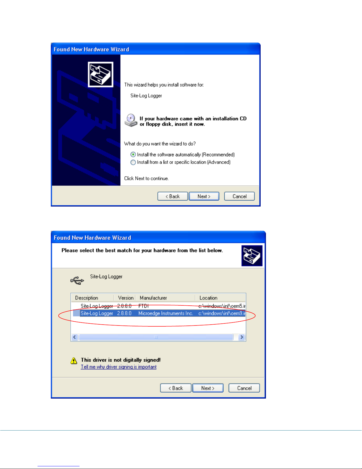
Select "Install the software automatically (Recommended)” as shown in the above figure and
then click "Next >".
Select the item with Manufacturer of Microedge Instruments Inc and click “Next>” to proceed.
PRECISE-LOG Data Loggers User’s Manual Page 30/57
Page 32
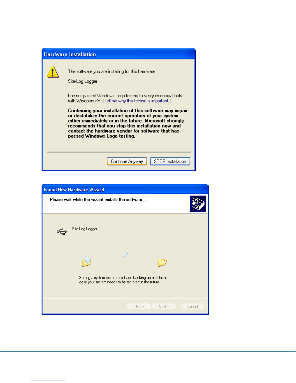
In the following message dialog, click "Continue Anyway" to continue with the installation:
The screen below will be displayed as Windows copies required driver files:
Windows should then display a message indicating the installation was successful:
PRECISE-LOG Data Loggers User’s Manual Page 31/57
Page 33
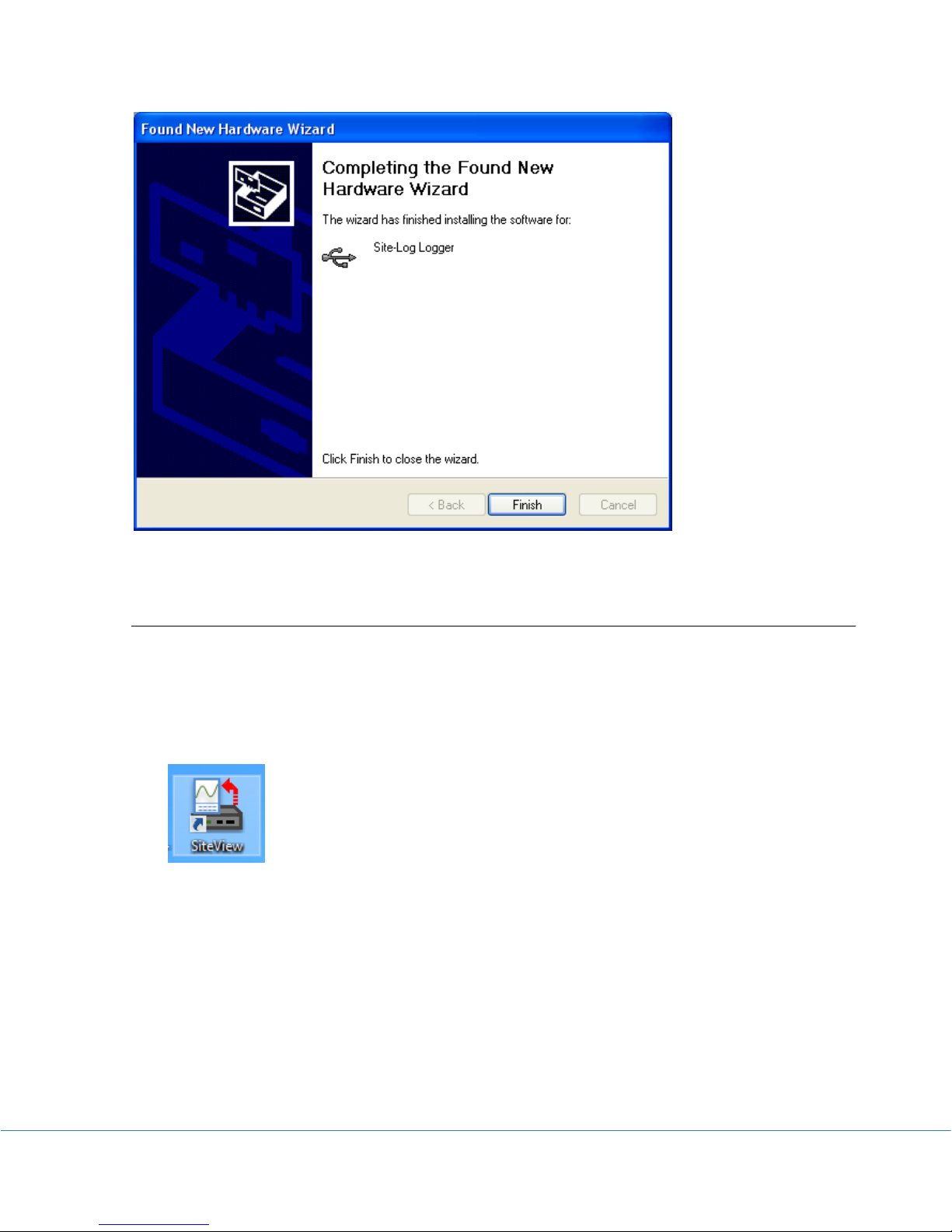
Activate SiteView
After the installation SiteView needs to be activated by entering Product Key you obtained
when you bought SiteView.
If the above installation of SiteView was successful, SiteView can be launched by either one of
the following methods:
Double click on SiteView icon on the desktop:
Or:
Using Windows Start Menu, select Start : All Programs: Microedge Instruments
Inc.: SiteView.
Double click “SiteView” icon on the desktop, and the following dialog appears:
PRECISE-LOG Data Loggers User’s Manual Page 32/57
Page 34
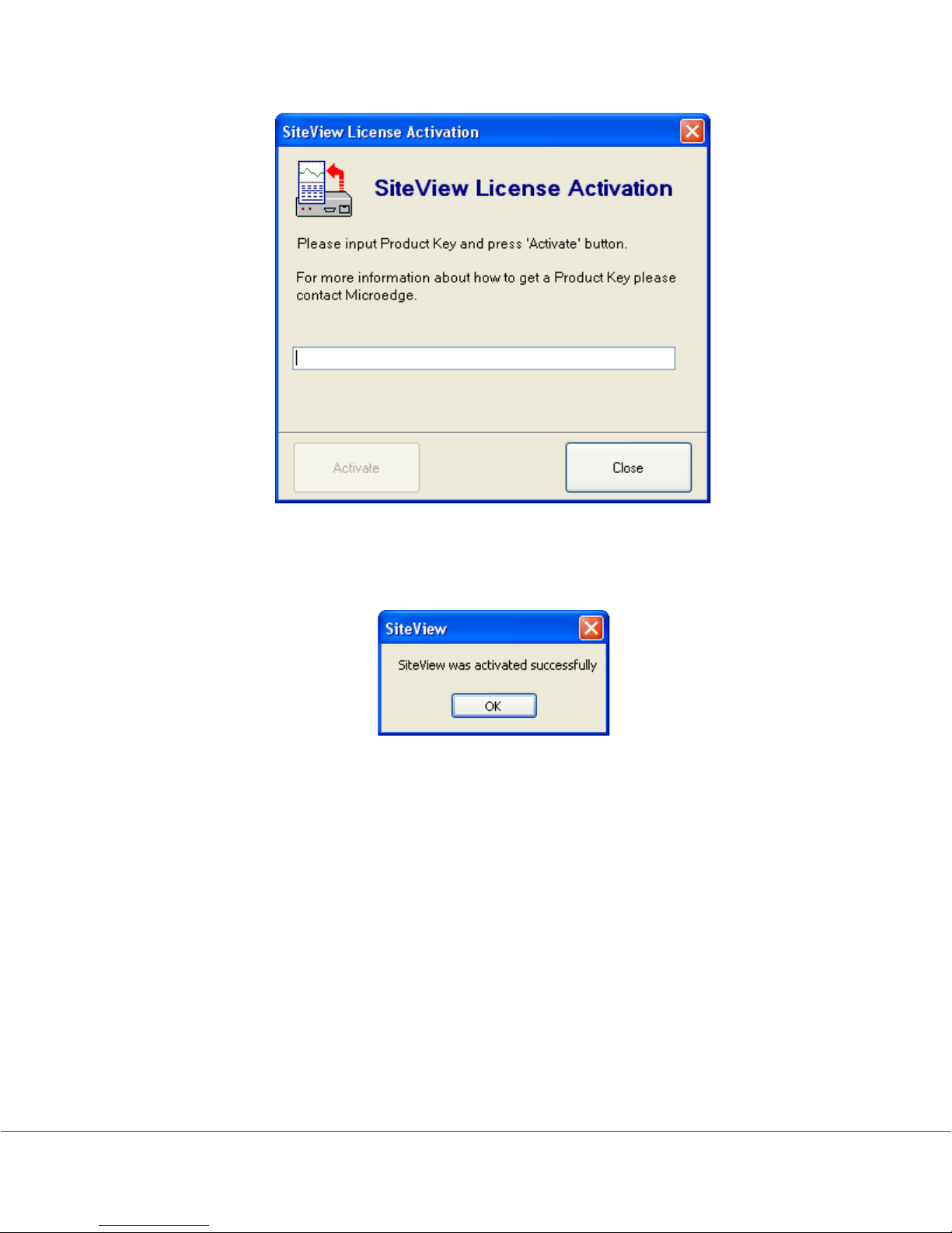
Enter the Product Key, then click the Activate button. If the Product Key is accepted the
following confirmation dialog will appear:
Click OK button to finish the activation. From now you can start using SiteView.
PRECISE-LOG Data Loggers User’s Manual Page 33/57
Page 35
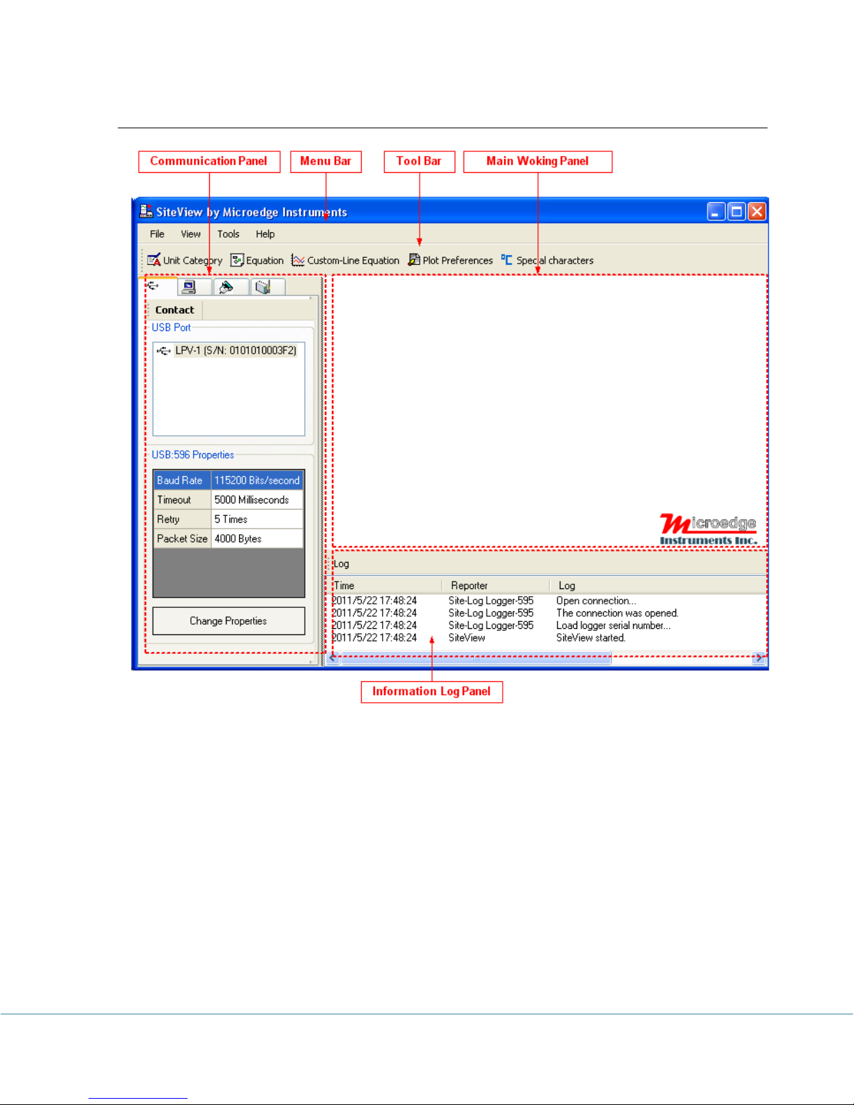
Main Window Frame
Communication Panel
The communication Panel contains USB, USB Device Server, Serial Port and Serial Device
Server communication tabs that are used to deal with the respective physical logger
connections to the computer. For instance, if the logger is connected to the computer via a
USB port you need to use USB tab to communicate with the logger.
Menu Bar
The Menu Bar contains File, View, Tools, and Help menus and their respective sub menus
that are used to complete various tasks.
Tool Bar
The Tool Bar provides an easy way to access the menu items by including some of the
frequently used items on the tool bar as the tool bar buttons.
PRECISE-LOG Data Loggers User’s Manual Page 34/57
Page 36
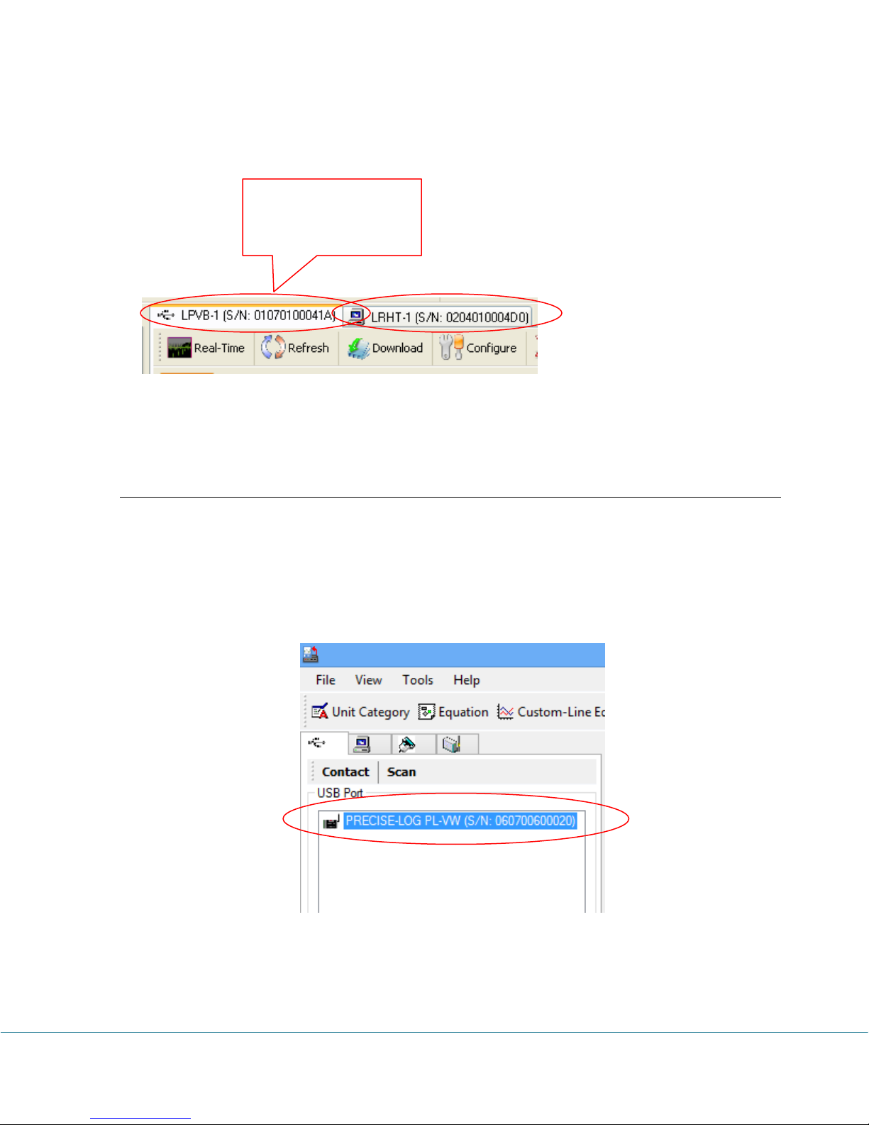
Main Working Panel
Click on each tab page
caption to view the
related page
The Main Working Panel contains a series Tab pages for logger status and the graph
information illustrated as the follows:
Information Log Panel
This section shows the information logs for any activities SiteView does. This is for
diagnostics and information purposes.
View Logger Status
This manual will use USB as an example of communications interface. For other
communications interfaces please refer to SiteView User’s Manual available for download
online.
If the logger is connected to the computer correctly the logger icon should show in USB tab of
the communication panel illustrated below:
Double clicking PRECISE-LOG Logger icon or clicking “Contact” button with the icon been
highlighted will bring up the logger status page.
PRECISE-LOG Data Loggers User’s Manual Page 35/57
Page 37
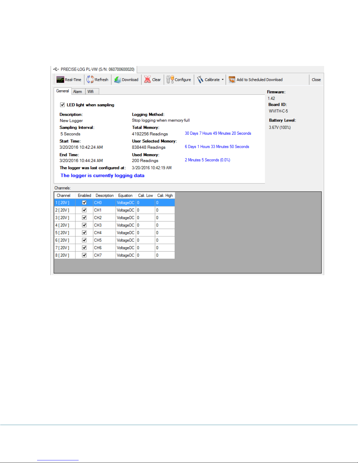
The status page shows the start and end time, sampling interval and other properties of the
connected logger:
General
This sub tab page displays the general properties of the logger.
Alarm
This sub tab page displays the properties regarding the alarm. By clicking the “Alarm” tab
page caption, the following page will appear:
PRECISE-LOG Data Loggers User’s Manual Page 36/57
Page 38
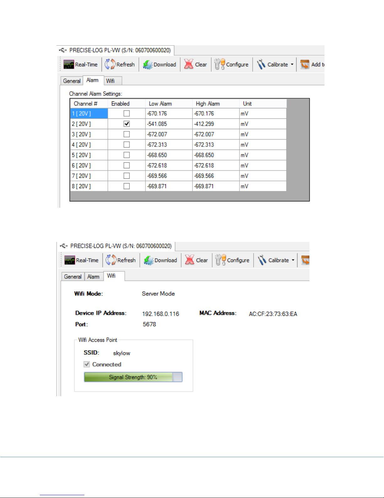
WIFI:
This sub tab page displays the properties regarding the WIFI:
Through the tool bar buttons you can act on other tasks described in the following chapters.
PRECISE-LOG Data Loggers User’s Manual Page 37/57
Page 39
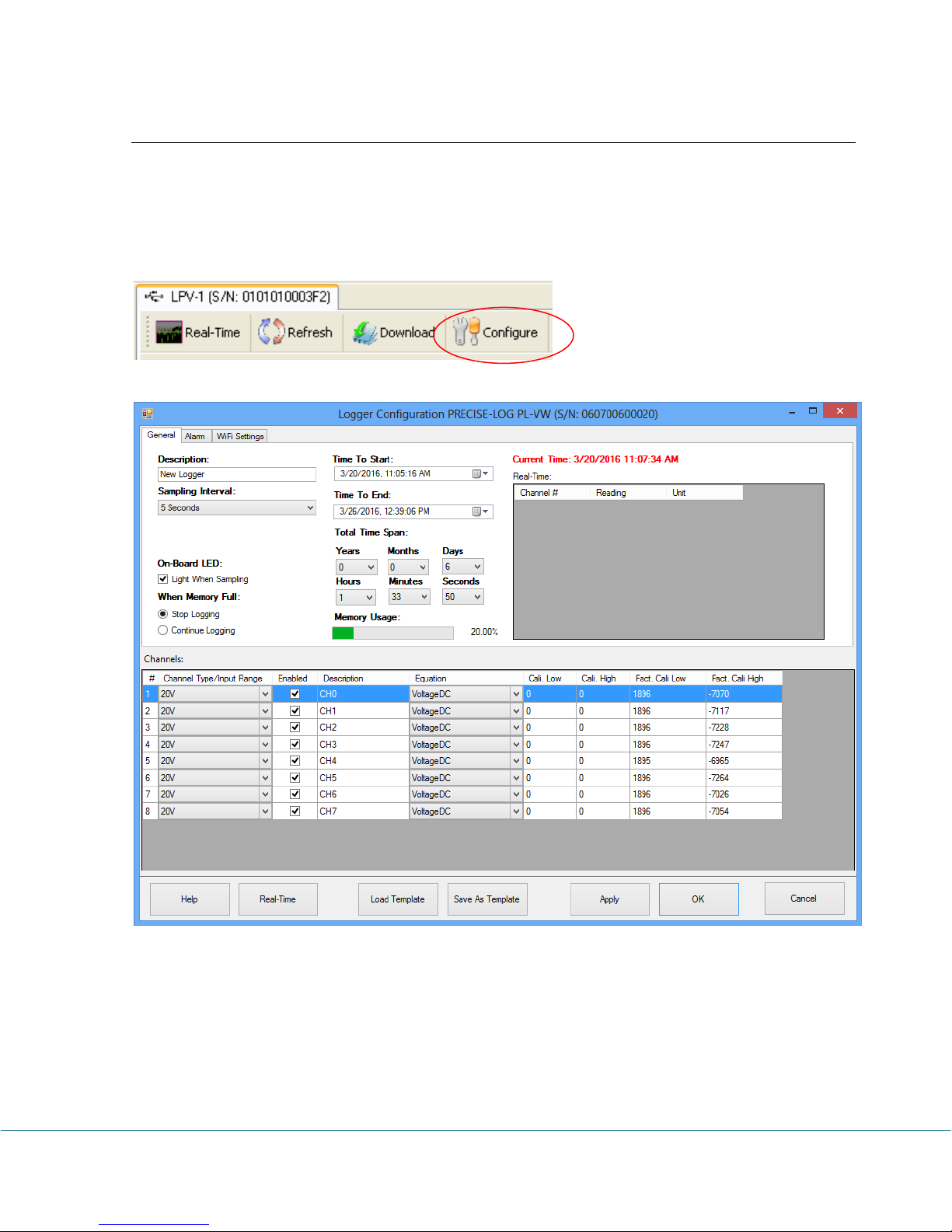
Configure Logger
Configuration of the logger is a procedure to edit the properties of the logger and to start the
new logging session.
If you are already in the logger status panel, clicking on the Configure button will bring up the
configuration dialog window:
There are three tab pages in this dialog. The General page is displayed in the above screen shot.
If you click Alarm tab the following page will appear:
PRECISE-LOG Data Loggers User’s Manual Page 38/57
Page 40
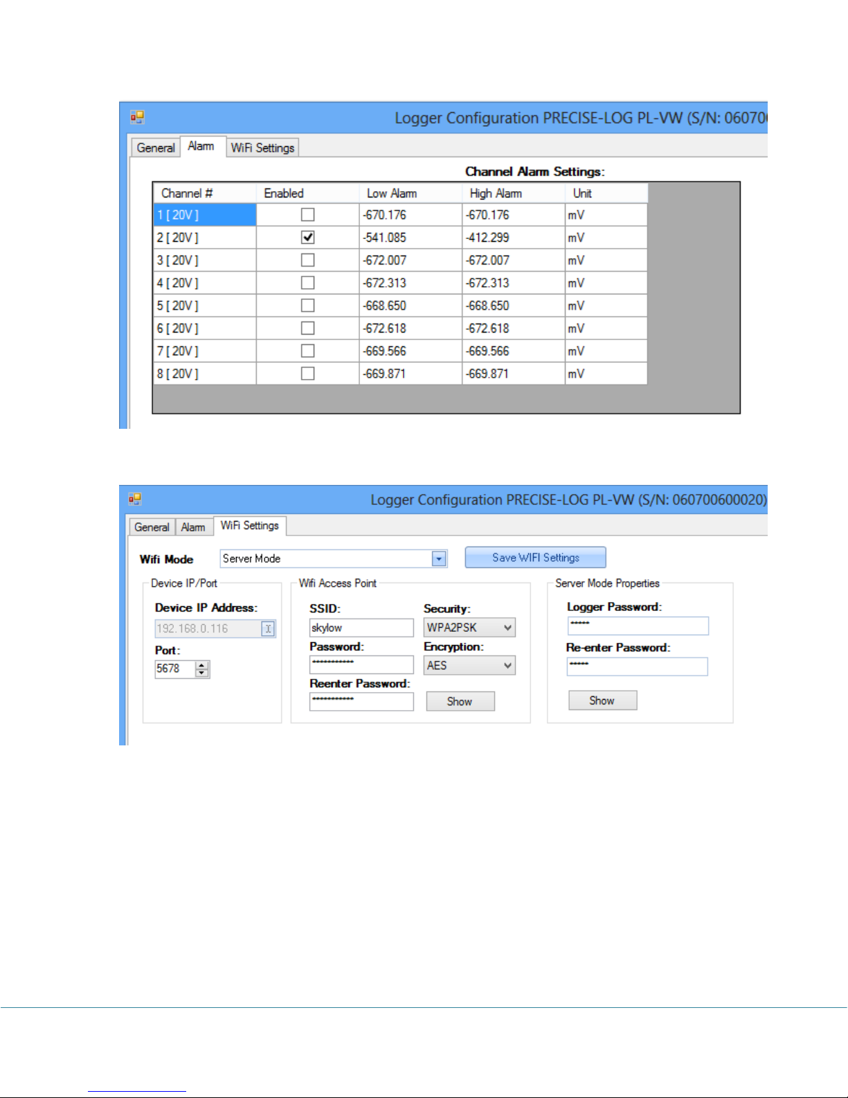
If you click WIFI Settings tab the following page will appear:
The following fields are for editing:
Description:
Description specifies the information about the logging session with a maximum of 30
characters. It will be the default Title section of the plot in the plot view.
Sampling Interval:
This field specifies the time span the logger will wait between two measurements sampling.
Valid settings are:
PRECISE-LOG Data Loggers User’s Manual Page 39/57
Page 41

Sampling Interval
1 second to 9 seconds in 1-second increment
10 seconds to 50 seconds in 10-second increment
1 minute to 59 minutes with 1-minute increment
1 hour to 12 hour with 1-hour increment
Making changes to the Sampling Interval will affect Total Time Span fields.
On-Board LED
Check this field to enable the on-board status LED. If the LED is enabled it will flash each
time when it samples data to indicate:
1. The logging is active if the LED flashes in green.
2. The logger is in alarm state if the LED flashes in red.
3. The battery will die soon if the LED flashes in amber.
If you do not need LED indication, you can uncheck this field to increase the battery life.
When Memory Full
If you want the logger to stop logging when the memory is full select Stop logging. If you
want the logger to continue logging and overwrite the oldest data with the new data (FIFO),
you choose Continue logging.
Time to Start & Time to End
These two fields specify the desired time the logger will start logging data and the time to
stop logging data.
Making changes to the Time to Start/End will affect Total Time Span fields mentioned later.
If you have selected the Continue logging field, when the memory is full, both start time and
end time will move forward accordingly.
Total Time Span
These fields are an alternate way to specify the total logging time from the start time you
specified above.
Changes made on these fields will affect Time to End field.
Channel Settings:
Enabled
Check this field to enable this channel for logging.
PRECISE-LOG Data Loggers User’s Manual Page 40/57
Page 42

Channel Range
This field specifies the measurement range the channel will use. Different channel types have
different input range selections. Please refer to Channels and Sensor Connections chapter
for details.
Description
This field specifies the name or the description of the channel (maximum of 30 characters).
Equation
This field specifies the equation used for the channel. Different channel ranges have different
default equations. Please refer to Channels and Sensor Connections chapter for details.
In order to convert a process signal to a correct measurement value an equation must be
applied to the channel.
For example, if you want to use the 0 – 5 VDC channel to record a battery voltage output,
the logger will first convert the battery voltage values to digital values and save them in the
memory. Later when all data are downloaded to a computer, SiteView will use equation
“VoltageDC” to convert the digital values back to voltage values.
If you are recording the voltage output of a transducer or transmitter and the range of the
voltage refers to another measurement unit, you will need to create your own equation for
this conversion. For instance, if your CO2 transducer outputs 0 – 5VDC representing 0 –
5000PPM of CO2, the custom equation you need to create looks like this:
public double CO2Equation(double Input)
{
double output;
output = 5000 * Input / 5 ;
return output;
}
For detailed instructions on how to create a custom equation please refer to the SiteView
User’s Manual available for download online.
Cali. Low & Cali. High
These two fields specify the custom calibration values that are used for measurement
adjustment.
Cali. Low value specifies the digital value that is over zero when the input value is in the low
range value (for 0 – 5 VDC channel the low range is zero volt). The equation will subtract
this value from the original digital value when doing the conversion.
Cali. High value specifies the digital value that is over 65535 when the input value is in the
high range value (for 0 – 5VDC channel the high range is 5 volt). The equation will subtract
this value from the original digital value when doing the conversion.
PRECISE-LOG Data Loggers User’s Manual Page 41/57
Page 43
The valid range for these two parameters is from –32768 to 32767.
These two parameters for each channel were originally set to zero when the logger was first
released.
If you have finished the Cali. Low and Cali. High calibration instructed in the later chapter,
the “Cali. Low” and “Cali. High” values may be readjusted.
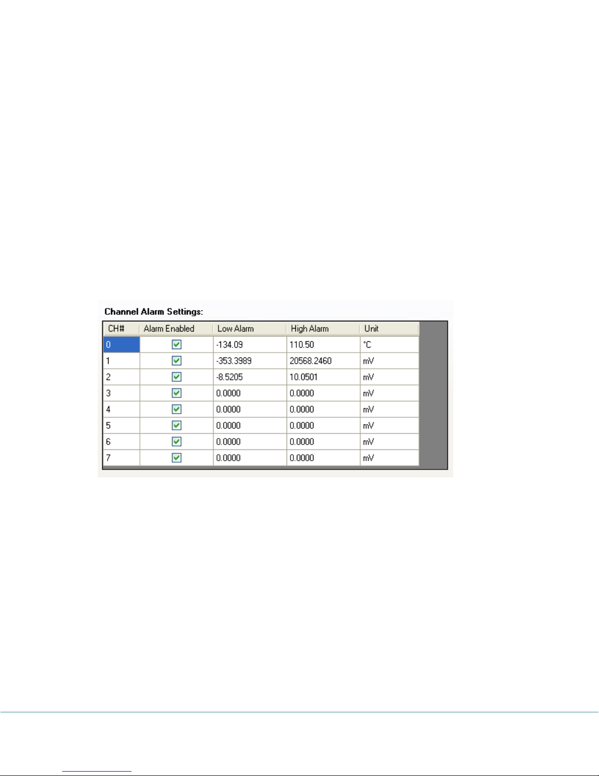
Alarm
This table specifies how each channel controls alarm state by:
Alarm Enabled: Check this field to associate this channel to the alarm state.
Low & High Alarm: These fields define the alarm thresholds. If the reading is beyond
these thresholds, the alarm is triggered.
WIFI Settings:
WIFI Mode:
Currently, only Wifi Function Disabled and Server Mode are available.
Wifi Function Disalbed: disable the wifi function
Server Mode: The logger will run as server and a client PC can
communicate with it.
Device IP/Port:
The device’s IP address is dynamically assigned by the router. You can specify the port the
device will work on.
Wifi Access Point:
This is the wifi network the logger will connect to.
PRECISE-LOG Data Loggers User’s Manual Page 42/57
Page 44
SSID: The name of the wifi network
Password: The password of the wifi network
Security: You can specify the following security: Open, Shared, WPAPSK,
WPA2PSK.
Encryption: You can specify the following encryption: None, WEP-H, WEP-A, TKIP,
AES.
Server Mode Properties:
You can specify a password at the logger level to prevent other clients from accessing
logger.
Save WIFI Settings:
Click this button to save wifi related settings to the logger. Then the logger will blink in
amber to indicate it is trying to connect to the wifi network. Once it successfully connected
to the network it will stop amber blinking and return to the normal operation.
Once you have finished making changes to the available settings, you can click OK button to
save the settings to the logger. The logger will start to record data from Time to Start you have
set.
Note: clicking on OK or Apply buttons will erase all existing measurements saved in the
logger.
For a detailed description of each available setting please refer to the SiteView User’s Manual
available for download online.
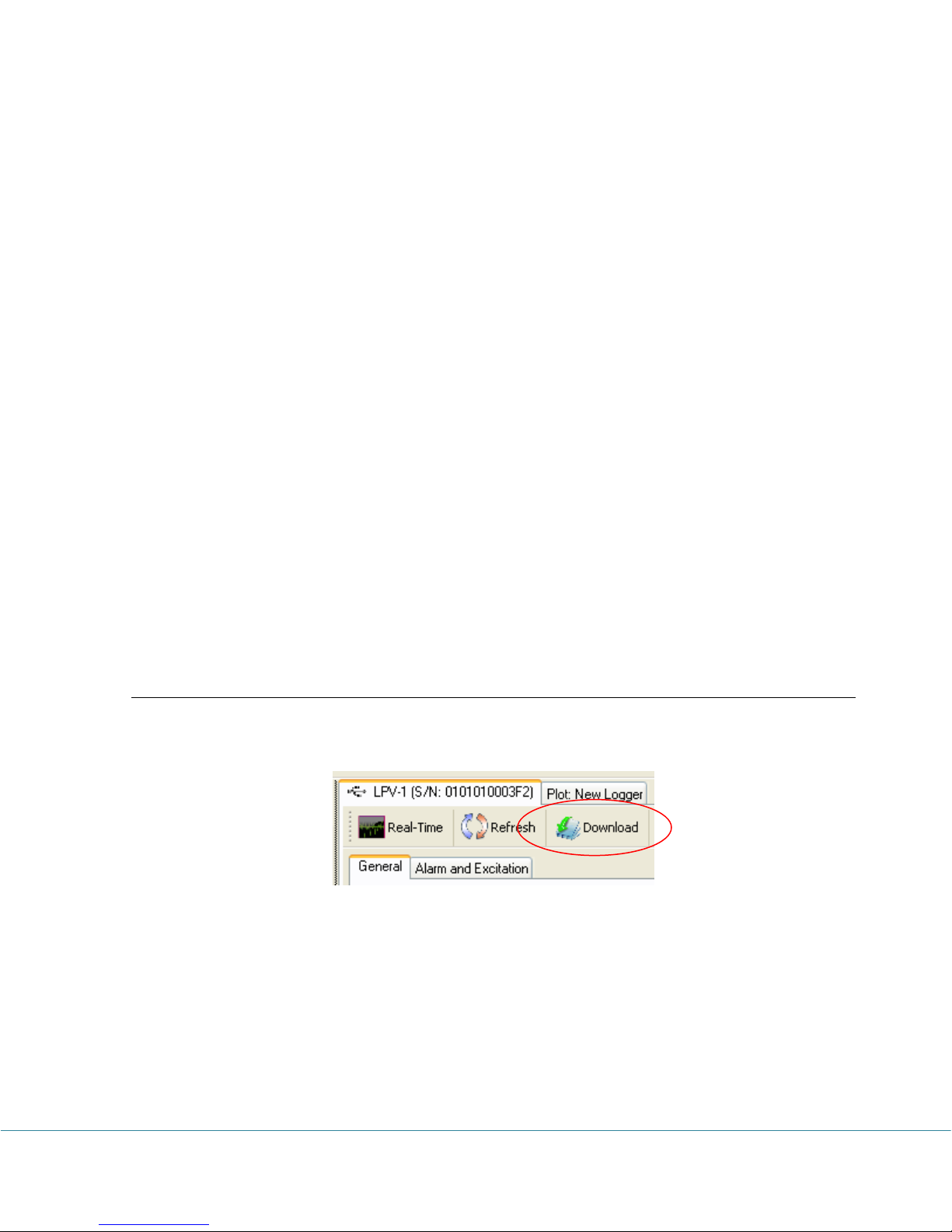
Download Logger
If you are already in logger status tab, clicking on “Download” button will bring up Download
dialog window:
PRECISE-LOG Data Loggers User’s Manual Page 43/57
Page 45
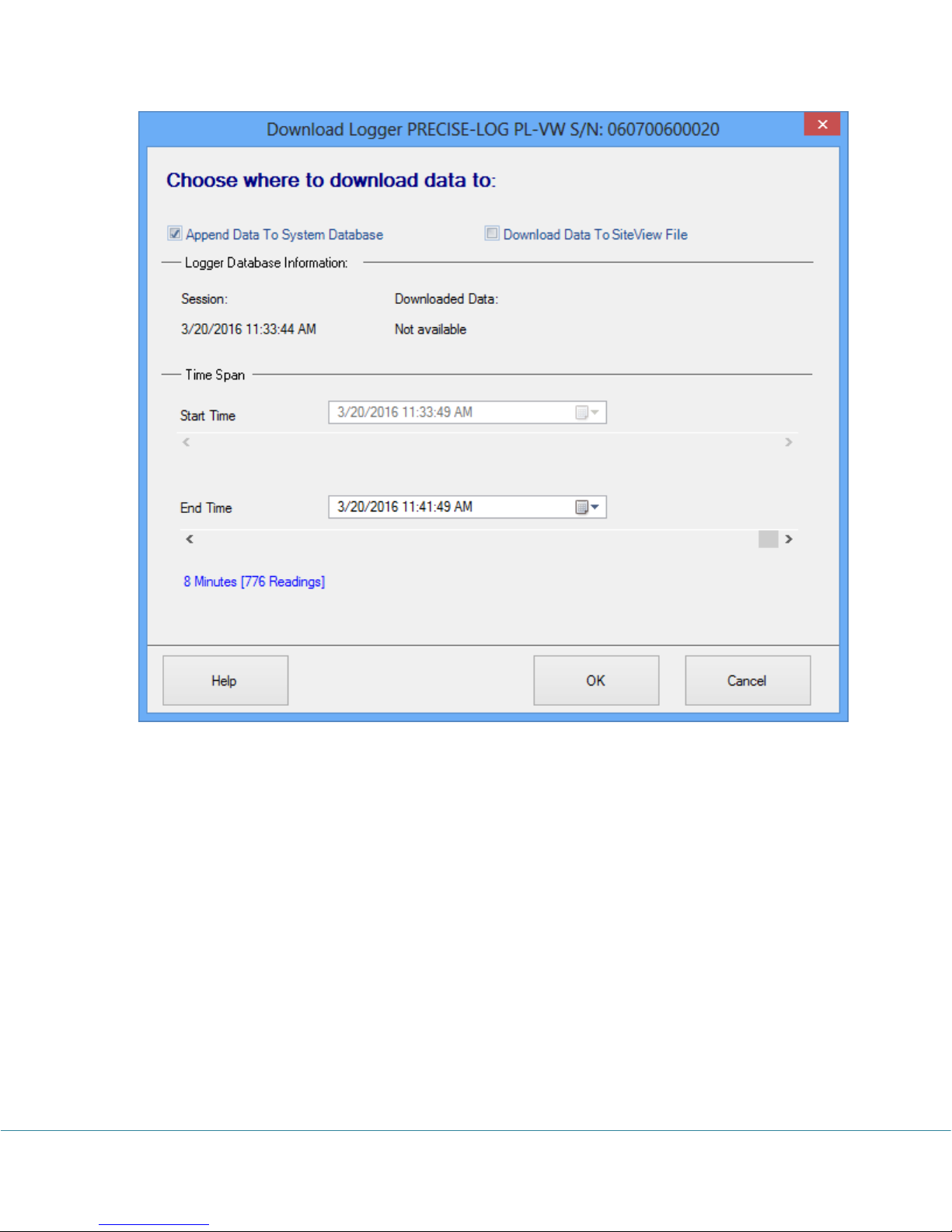
Started from Site View 3, data can be downloaded to the system database. Each data logger has
a life-time database file associated to it. If you choose to “Append Data to System Database”
you can specify End Time and start to download the data.
If you choose to download data to a separate Site View file, the user interface looks like:
PRECISE-LOG Data Loggers User’s Manual Page 44/57
Page 46
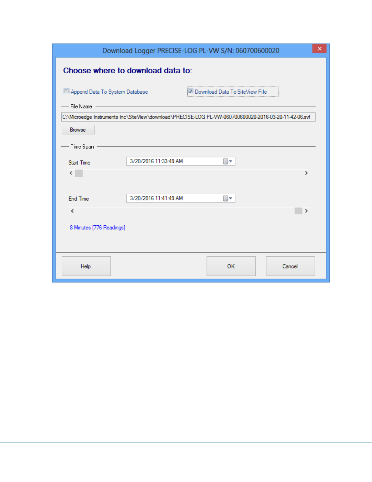
The fields that you can edit are:
Filename & Browse
These fields specify the full file path the downloaded data will be saved into.
Clicking on Browse button will display File Save dialog where you can edit or choose a file
name.
Start Time & End Time
These fields specify the desired start and end time for the data to be downloaded. You can
use either scroll bars or the calendar controls to change the start and end time.
Once you have selected a desired time frame you can click OK button to start the download
process.
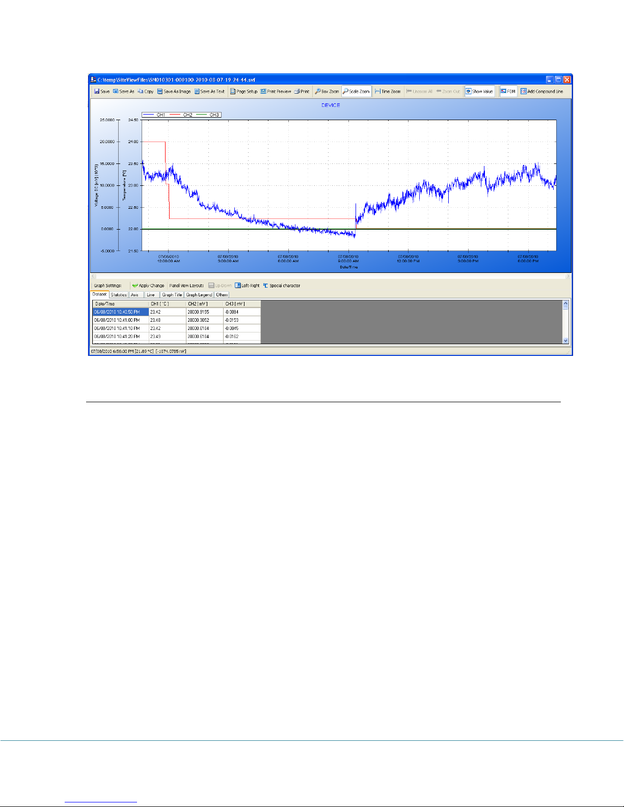
After the download the plot and tabular data will be displayed (If Display plot after download
was not checked the plot will not display):
PRECISE-LOG Data Loggers User’s Manual Page 45/57
Page 47
Real-Time Display
SiteView can view the real-time measurements while the logger is still logging data. The realtime display shows the list of the latest channel real-time measurements, as well as the trend
chart of all channel real-time measurements for the past given period of time from the current
time.
To open real-time view, if the logger has been contacted and the status of the logger is
displayed, click on Real-Time tool bar button. The following real-time dialog appears:
PRECISE-LOG Data Loggers User’s Manual Page 46/57
Page 48
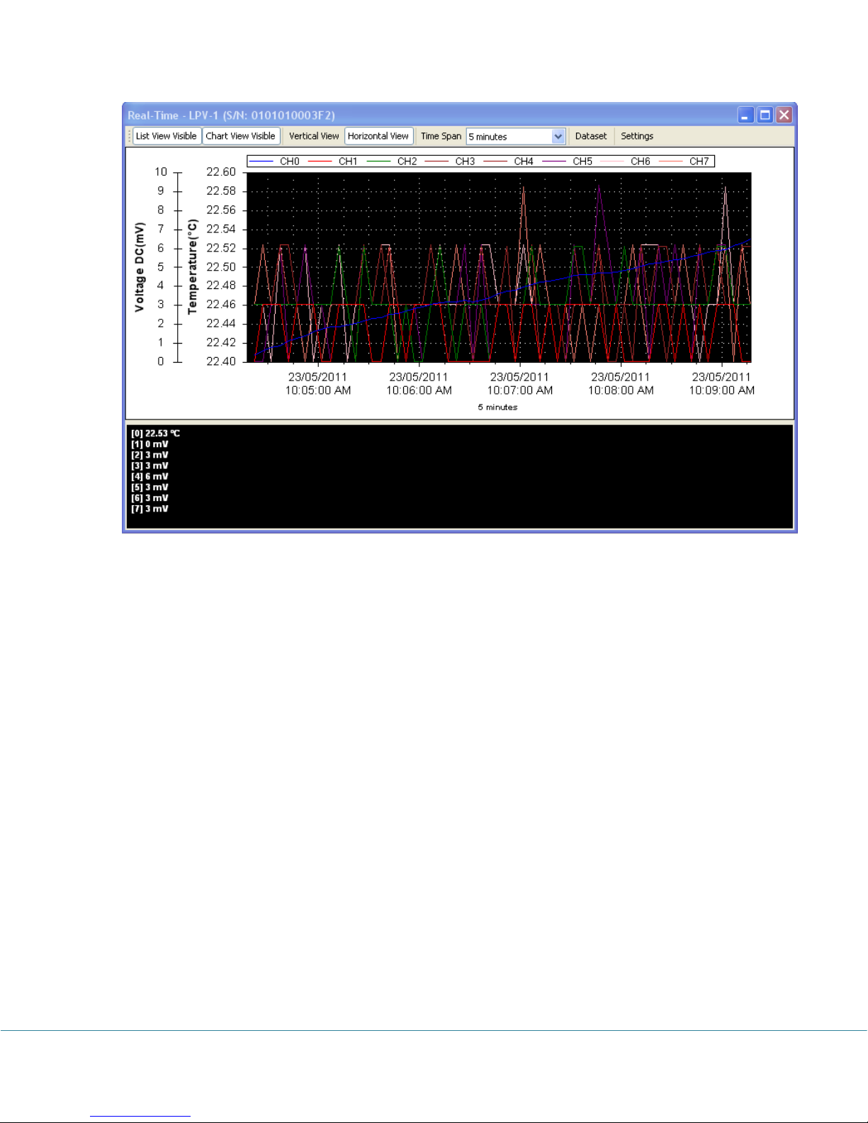
Real-Time in Horizontal View
PRECISE-LOG Data Loggers User’s Manual Page 47/57
Page 49
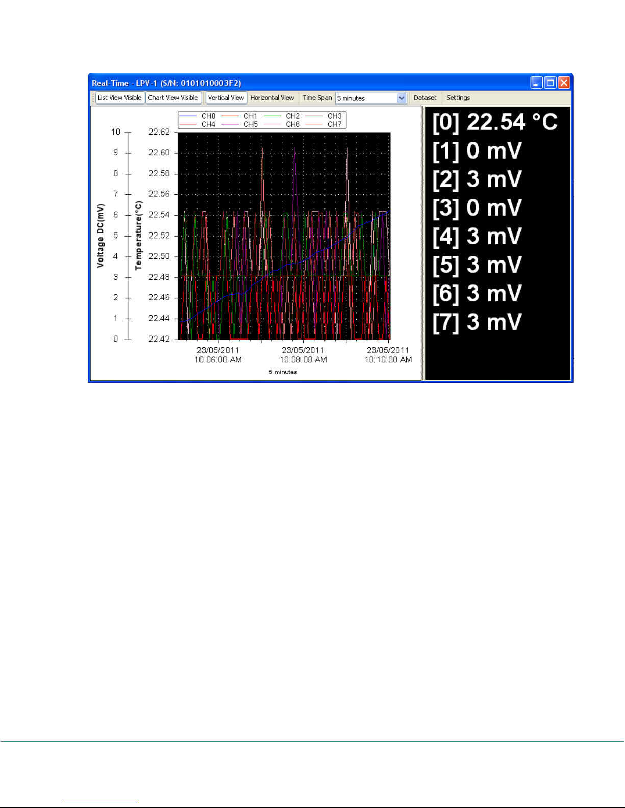
Real-Time In Vertical View
Tool bar buttons:
List View Visible
Click to show/hide the list view panel.
Chart View Visible
Click to show/hide the chart view panel.
Vertical View
Click to display the chart and list views vertically.
Horizontal View
Click to display the chart and list views horizontally.
Time Span
This field allows changing the time span for the chart view. Available settings are:
PRECISE-LOG Data Loggers User’s Manual Page 48/57
Page 50
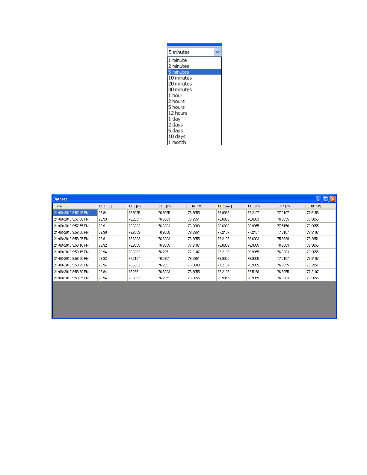
Dataset
Click to display the tabular view of the recorded measurements illustrated below:
Settings
Click to display more properties illustrated below:
PRECISE-LOG Data Loggers User’s Manual Page 49/57
Page 51
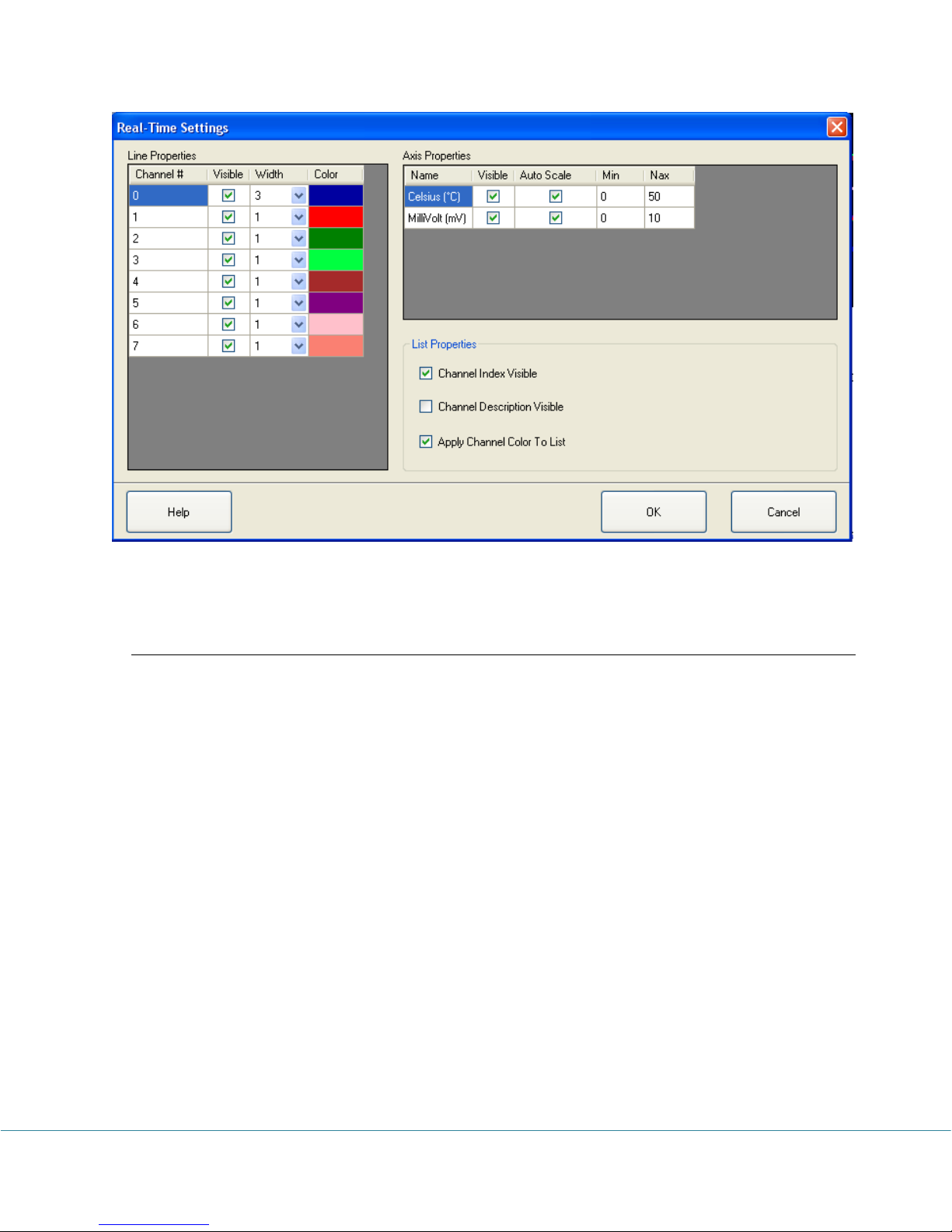
For detailed instructions on how to change real-time view settings please refer to SiteView
Instruction Manual available for download online.
Calibrate a Channel
SiteView software provides two-point calibration for most of the loggers.
Understand Cali. Low & Cali. High
In the logger status page, there are two properties for each listed channel called Cali. Low
and Cali. High. These two fields specify the calibration values that are used for
measurement adjustment.
Cali. Low value specifies the digital value that is over zero when the input value is the
lowest value (for 0 – 5 VDC channel the lowest value is zero volt). For instance, if you apply
zero volt input and the logger measured 100 as the digital value, then Cali. Low should be
100 digits. The equation entity will subtract this value when resolving the correct lowest
digital value.
Cali. High value specifies the digital value that is over 65535 when the input value is the
highest value (for 0 – 5VDC channel the high range is 5 volt). For instance, if you apply 5
volt voltage to the channel and the logger measured 65100 as the digital value. Then Cali.
High is “- 435” (calculated from 65100 – 65535). The equation entity will subtract this
value (-435) from the digital value when resolving the highest digital value.
The valid range for these two parameters is from –32768 to 32767.
PRECISE-LOG Data Loggers User’s Manual Page 50/57
Page 52
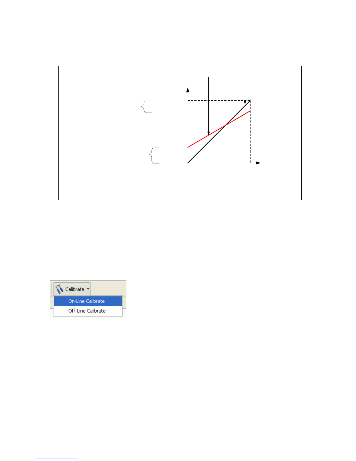
The following figure illustrates the relationship between an ideal data line and a measured
Max. = 65535
Max. = 65535
Min. = 0
Min. = 100
Max. = 65100
Measured Data Ideal Data
Input
Output
Cali. Zero = 100 – 0 = 100
Cali. Span = 65100 - 65535 = - 435
After Correction, Min. Value = 100 – 100 = 0
After Correction, Max. Value = 65100 – ( - 435) = 65535
data line and how Cali. Low and Cali. High correct the measured data line.
Decide On-Line or Off-Line Calibration
If the source signal like voltage or current can be connected to the logger while the logger is
connecting to the computer, you can calibrate the logger on-line. If the source signal like a
temperature or relative humidity is not available for on-line calibration, you can calibrate the
logger off-line after the logger has recorded the low and high point data.
You access On-Line / Off-Line Calibration via Calibrate button on the logger status tool bar.
The following dialog appears:
PRECISE-LOG Data Loggers User’s Manual Page 51/57
Page 53
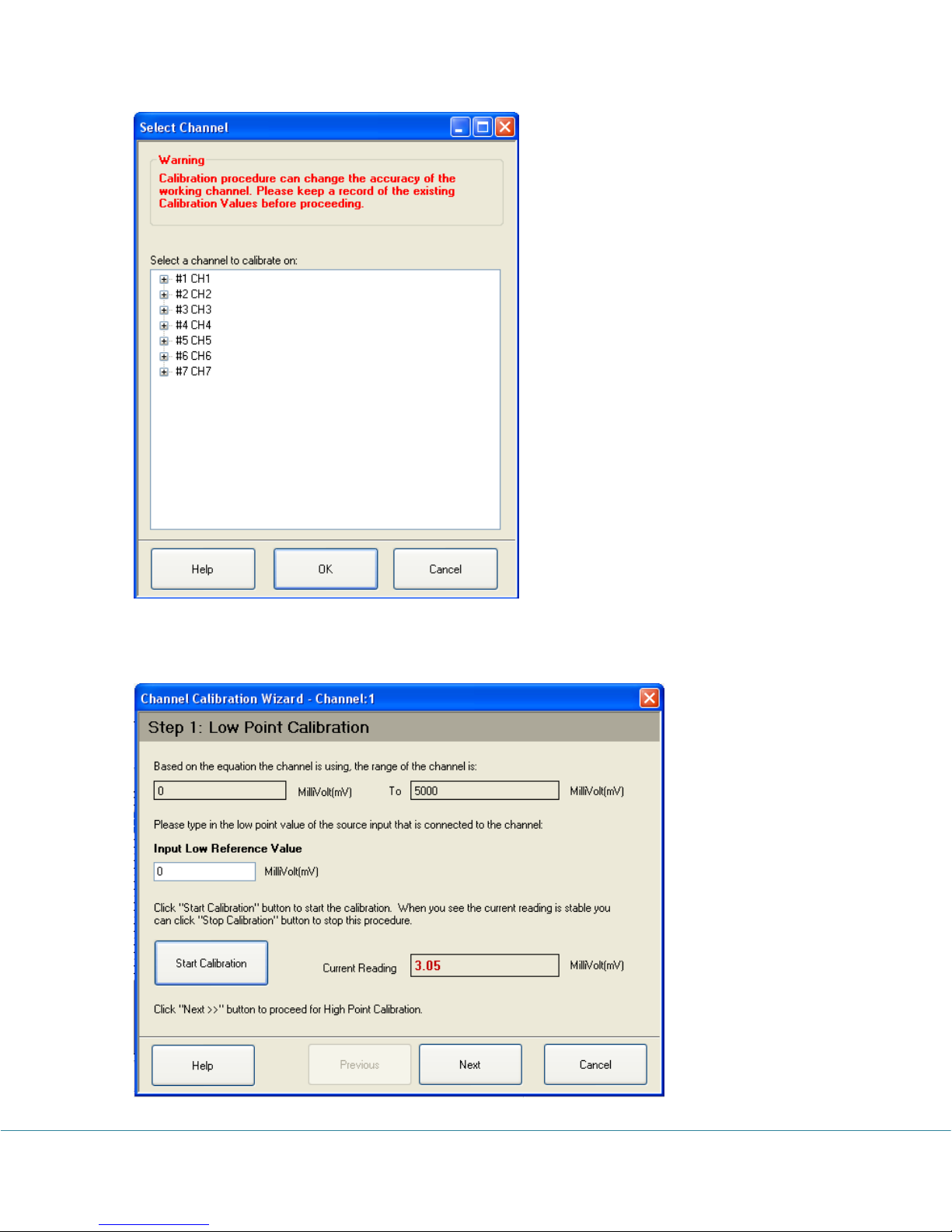
Select the channel you want to calibrate on and click OK button. The calibration dialogs appear
as follows:
PRECISE-LOG Data Loggers User’s Manual Page 52/57
Page 54
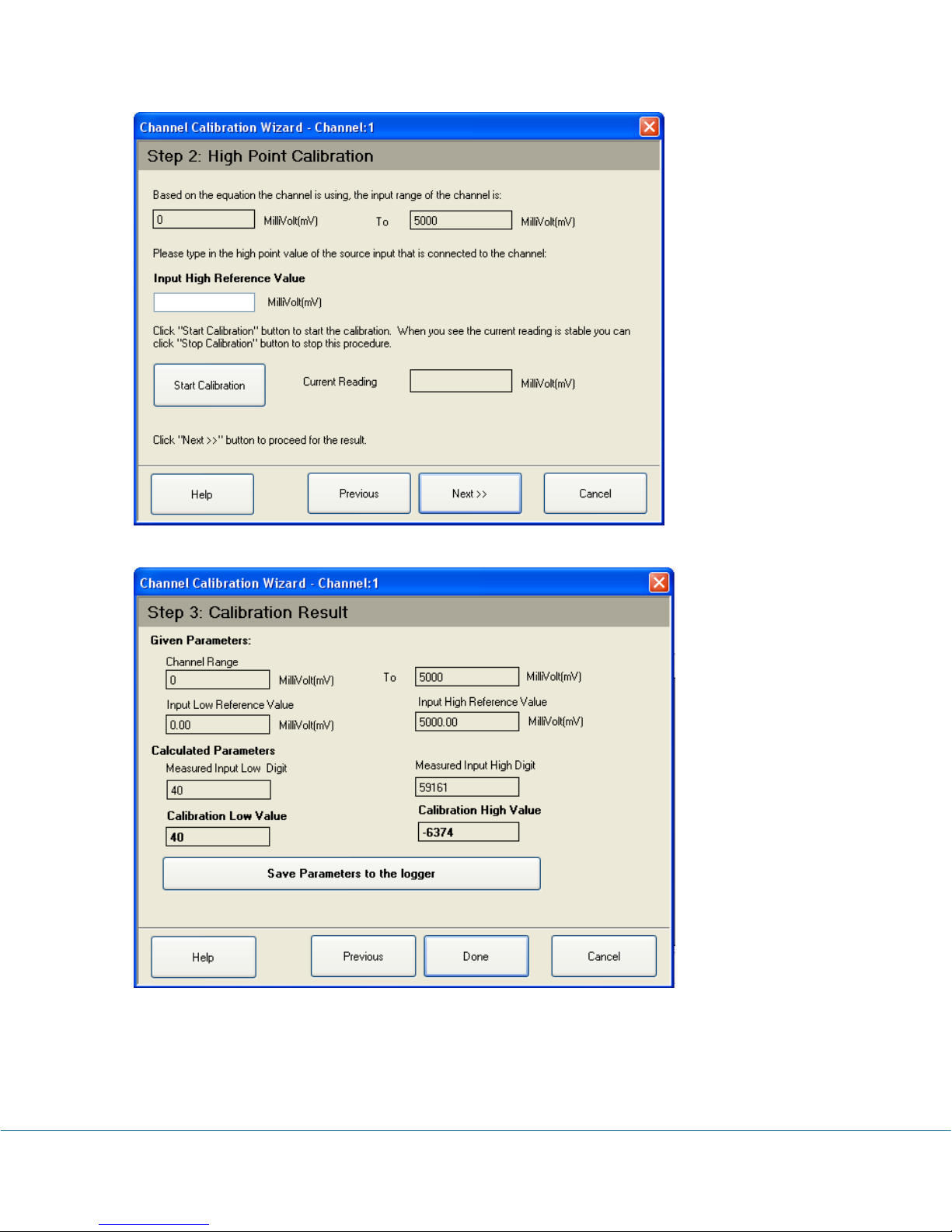
The above dialogs are for On-Line Calibration.
PRECISE-LOG Data Loggers User’s Manual Page 53/57
Page 55
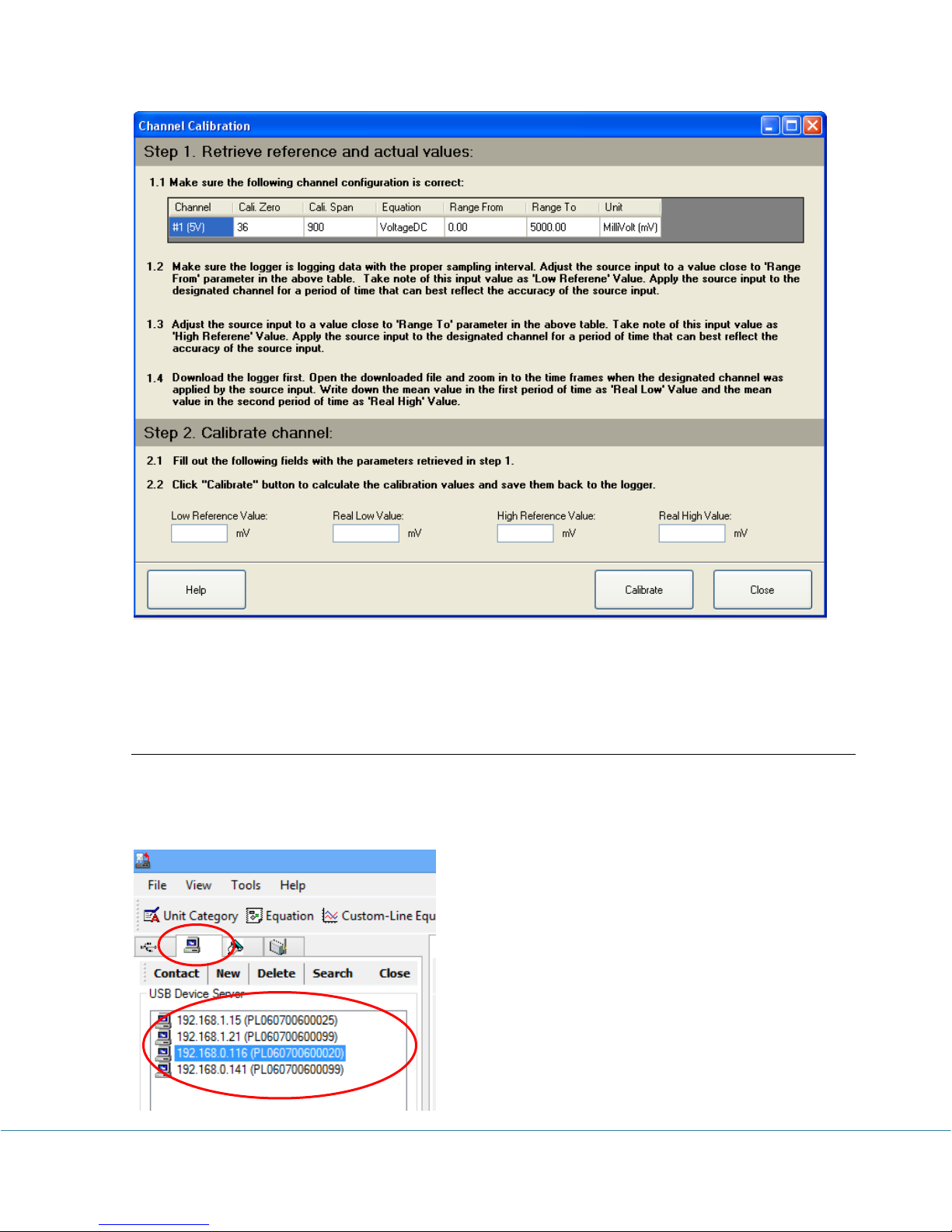
The above dialog is for Off-Line Calibration.
Please refer to Calibrate Logger chapter in SiteView User’s Manual for details.
Communicate with PRECISE-LOG Wirelessly
Once you have configured the logger with correct WIFI propertied, the logger will register with
the WIFI network. Then within one minute, SiteView will automatically scan the network for
PRECISE-LOG loggers and list them under USB Device Server tab:
PRECISE-LOG Data Loggers User’s Manual Page 54/57
Page 56
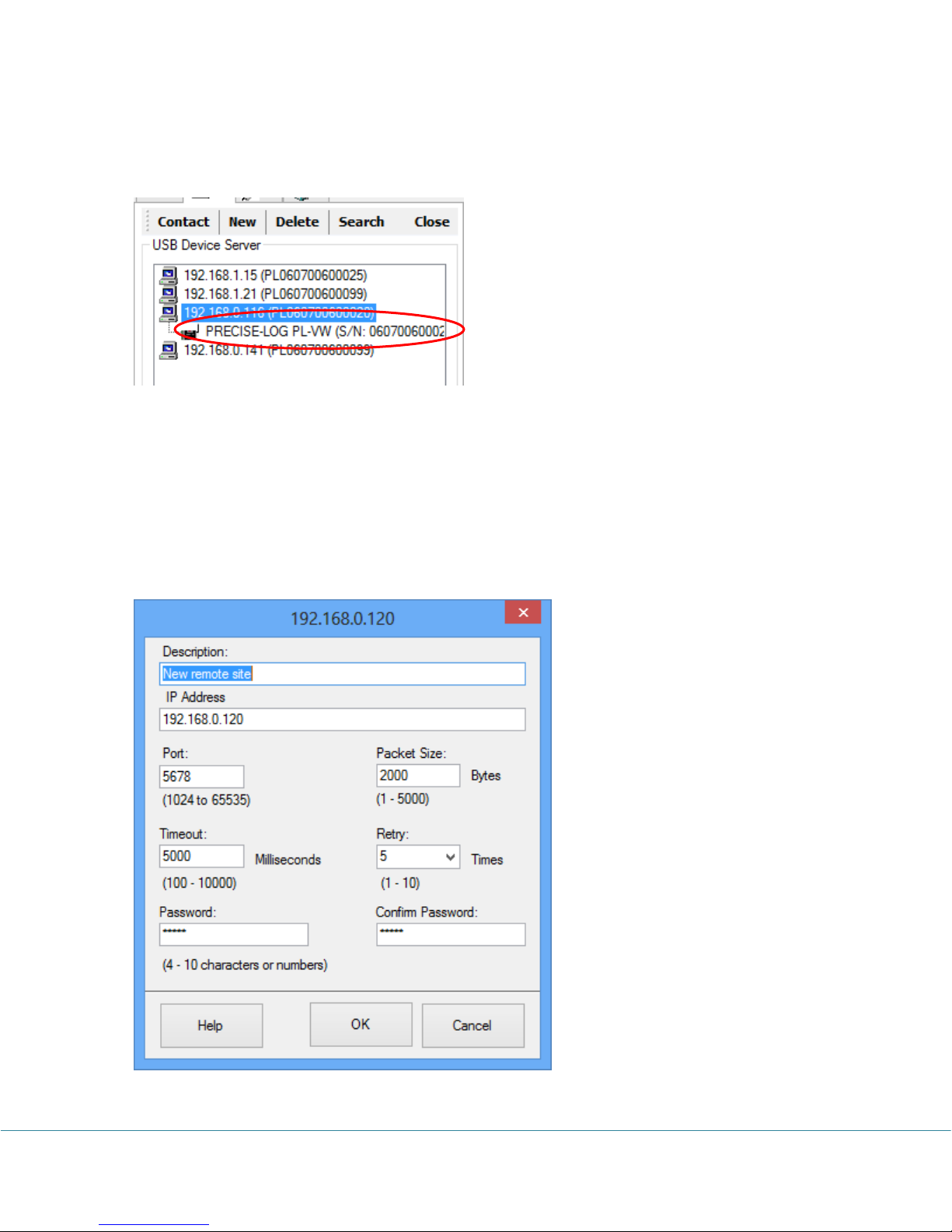
The entry contains the IP address plus “PL” plus the logger’s serial number.
To communicate with the logger, you double click the entry, the logger will show as below:
Then you double click the logger icon to show the status window of the logger.
If the logger was not added to the USB Device Server tab, please make sure the computer or
router is not blocking port 48899 on UDP communication.
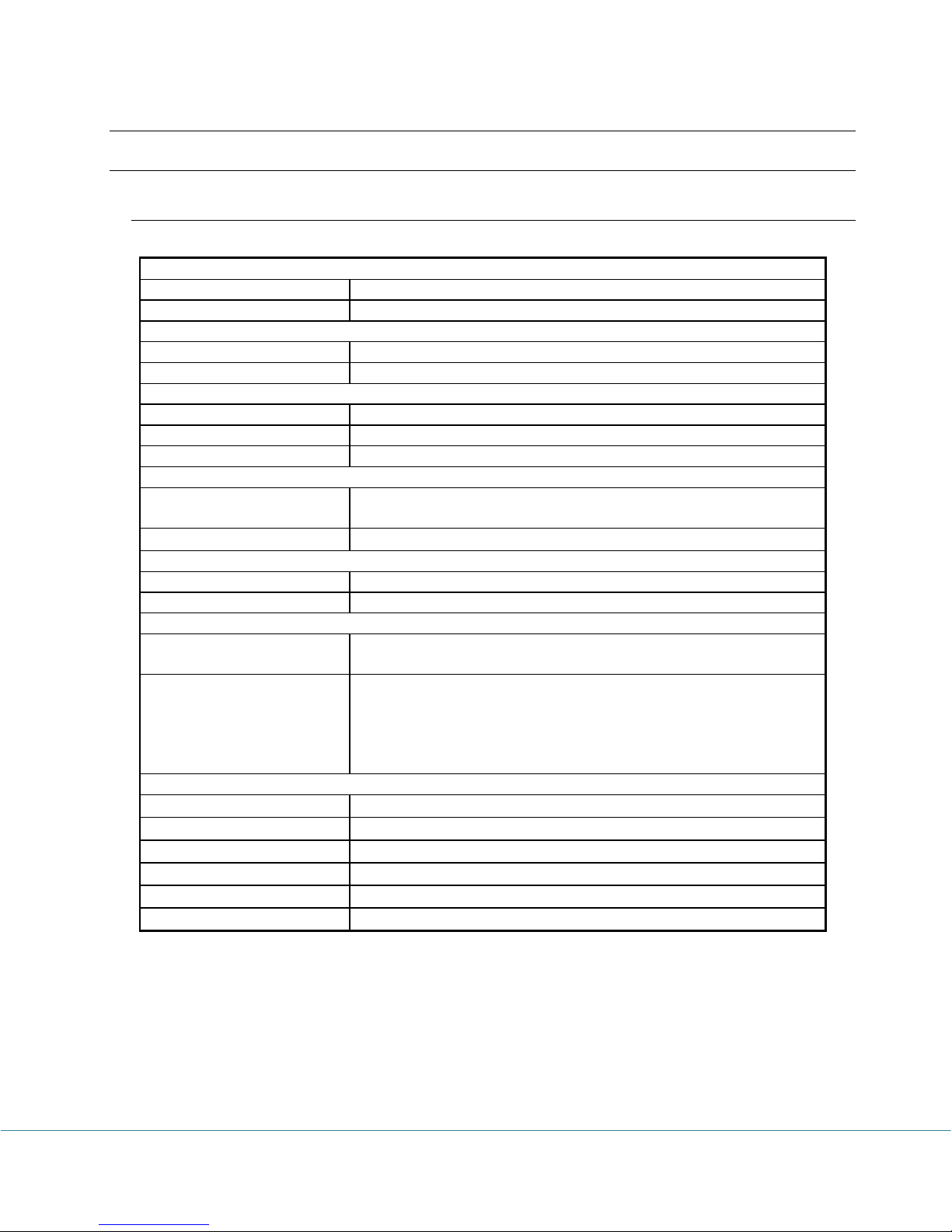
You can always add a new connection under USB Device Server by clicking “New” button. In
the below dialog, fill out the descripiotn, IP address of the logger and leave other sections
default. Once the connection was added you can double click it to communictate with the logger.
PRECISE-LOG Data Loggers User’s Manual Page 55/57
Page 57
66.. SSppeecciiffiiccaattiioonnss
Alarm
Channel Alarms
Two editable alarm thresholds per channel.
Alarm Indicator
On-board LED lights in red when in alarm state.
On-board Memory
Capacity
8 Mega-bytes (4 Mega measurements)
Data Retention
Over 20 years
Sampling & Logging
Sampling Interval
1 second to 12 user selectable.
Logging Mode
Stop recording or FIFO when memory is full.
Logging Activation
Programmable instant, start delay or field push button activation.
Communications
Interface
USB (Mini-USB-B) (USB-A-mini USB-B Cable included)
WIFI module for W series
Baud Rate
115200 bps
Battery
Power
Built-in 3.6V Lithium Battery.
Life Cycle
10 years based on 1 minute sampling interval in stand-alone mode.
Software
SiteView
[1]
Configuration, downloading, scheduled downloading, plotting,
real-time plotting, custom calibration and custom equation
Software Requirements
Computer with 1.0 GHZ or faster processor
1.0 GB Memory or higher
1.0 GB of available hard-drive space or higher
Windows XP with SP2 or later, Vista, Window 7
At least one USB port.
WIFI Module
[2]
Standard
802.11b/g/n,
Frequency Range
2.412 – 2.484GHz
Transmit Power
11-18 dBm
Receive Sensitivity
-82 to -93 dBm
Security
WEP/WPA-PSK/WPA2-PSK
Encryption
WEP64/WEP128/TKIP/AES
Common Specifications
PRECISE-LOG Data Loggers User’s Manual Page 56/57
Page 58
Physical
Material
Aluminum Enclosure.
PCB Treatment
Conformal coating
Dimension
88 X 64.2 X 24 mm
3.46 X 2.53 X 0.95 Inches
Weight
200g
Mounting
Probe/wall-mount holes for hanging/mounting.
Others
LED Indicator
Tri-Color LED: (can be disabled for power saving)
Normal Sampling: green when sampling.
Alarm: red when sampling.
Low Battery: amber when sampling.
Operating Environment
-40 ~ +70°C (-40 to + 158°F), 0 ~ 95 %RH non-condensing.
Clock Accuracy
+/- 1 minute per month
Approvals
CE, FCC
Sampling
Interval
Enabled
Channel
Logging
Capacity
1 minute
1
8 years
1 minute
2
4 years
1 minute
8
1 year
10 seconds
1
485 days
10 seconds
2
242 days
10 seconds
8
60 days
Sampling
Interval
Enabled
Channel
Logging
Capacity
1 second
1
48 days
1 second
2
24 days
1 second
8
6 days
[1]: Sold separately.
[2]: Must be powered by external 5VDC power supply via Mini-USB Port.
Logging Capacity
PRECISE-LOG Data Loggers User’s Manual Page 57/57
 Loading...