

Page 1
Technical Instruction
1 | 13
Form-No: TI-WW006 // Revision: B // Date: Jul. 5, 18
MICRODYN BIO-CEL® L-1
Replacement of Cassette and Diffuser
Safety Precautions & Storage Conditions
Important Information
The regional safety precautions must be fulfilled that the required work can be performed
onsite. The fulfillment of these safety precautions is not a duty of MICRODYN-NADIR.
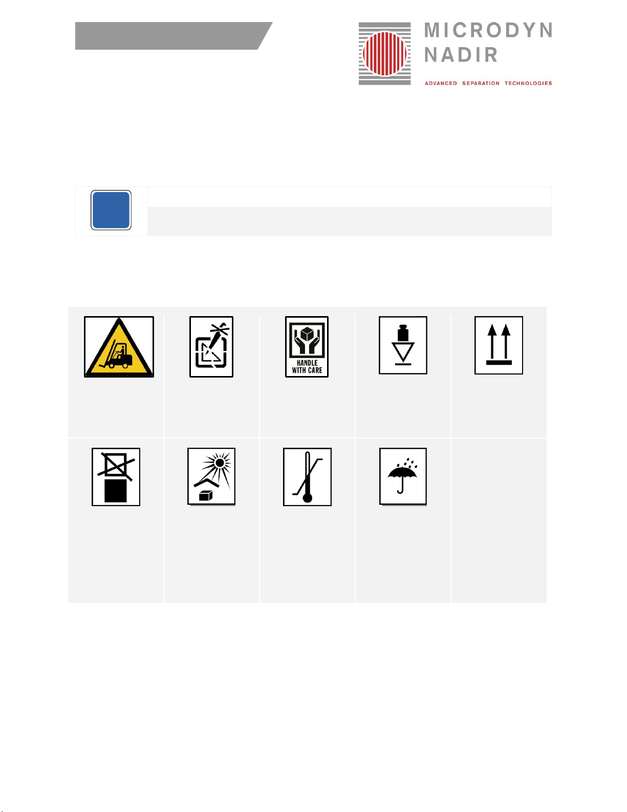
To transport and temporarily store the module before installation, please consider the safety instructions
listed below. These instructions are also listed on the packaging.
Please note that diffusers are very sensitive against direct sunlight and sharp materials. Be careful when
opening the package and handling with the diffusers.
Transport with
forklift only.
Do not damage
outer packaging
at the top.
Handle the
product with care.
Packaging is
top-heavy.
Store packaging
upright with arrows
directed upwards.
Do not stack the
modules.
Protect from
direct sunlight.
Store in the
following
temperature
range only:
5°C - 40°C
(40°F - 104°F).
Protect from
moisture
(< 70 %).
i
Page 2
2 | 13
Form-No: TI-WW006 // Revision: B // Date: Jul. 5, 18
Materials
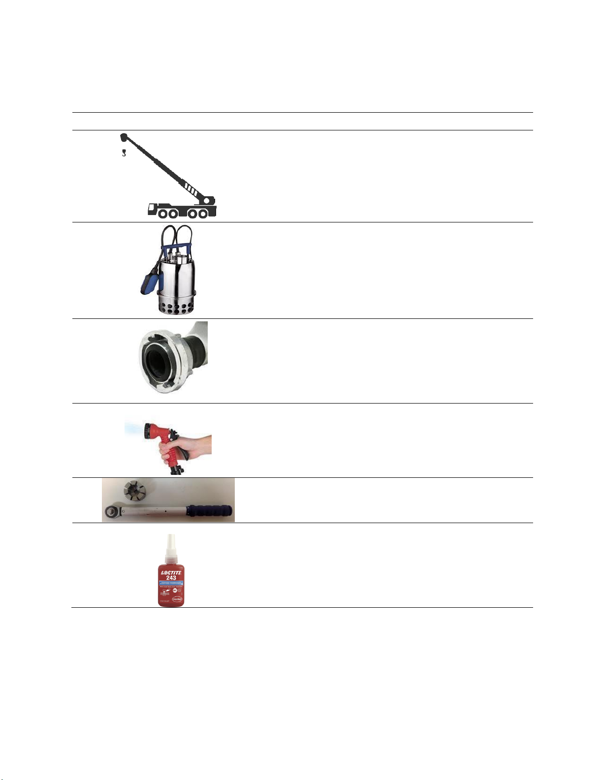
The following materials are needed on site to perfom a replacement of a cassette and/or diffuser
Table 1. Materials needed to perform diffuser change
Picture
Description
Crane to lift membrane module out of tank incl. lifting tool
or chains in case work is carried out outside.
Max. weight for lifting 2800 kg.
Make sure you have a flat floor with bearing load of 2000
kg/m2.
Submerged pump to drain tank totally. If no sump pit is
available, a vacuum cleaner is highly recommended to get
the tank bottom totally cleaned and drained.
Water hose 3 inch to clean membrane modules and water
or mixed liquor supply with 5 to 10 l/s (80 to 160 gpm) for
dewatering of membrane modules if required
Sprinkler system for keeping membrane cassettes wet,
while replacing diffusers.
Torque wrench with special socket wrench for diffuser
exchange (available on request)
Loctite 243 or equivalent to apply on screws
Page 3

3 | 13
Form-No: TI-WW006 // Revision: B // Date: Jul. 5, 18
Introduction & Handling Rules for Cassettes and/or Diffuser Tubes
• When replacing the cassette or/and the diffuser tubes MICRODYN-NADIR strongly
recommends reading this technical instruction carefully and exactly following the instructions.
• Please note the safety and storage conditions described above and in the BIO-CEL® operation and
maintenance manual.
• In case of diffuser change, make sure to keep the membranes of the cassette wet.
• In case of cassette change please note, that once the membranes got wet, it must not dry out again.
• Make sure that nothing can potentially cause damage to the membranes or diffuser tubes during
assembly and installation.
• The diffuser tubes of the BIO-CEL® modules are developed and adjusted for the operation of the
modules. Therefore, in case of a necessary replacement of the diffuser tubes, the original diffuser
tubes supplied by MICRODYN-NADIR must be used. Other diffuser tubes may not ensure a proper
operation and can cause irreversible module damage.
Please note that improper handling and installation of the diffuser tubes can cause incorrect aeration
of the BIO-CEL® modules, which can again lead to major damages of the whole module.
In case of any questions please contact your responsible MICRODYN-NADIR sales contact.
Page 4
4 | 13
Form-No: TI-WW006 // Revision: B // Date: Jul. 5, 18
Available Accessories and Spare Parts
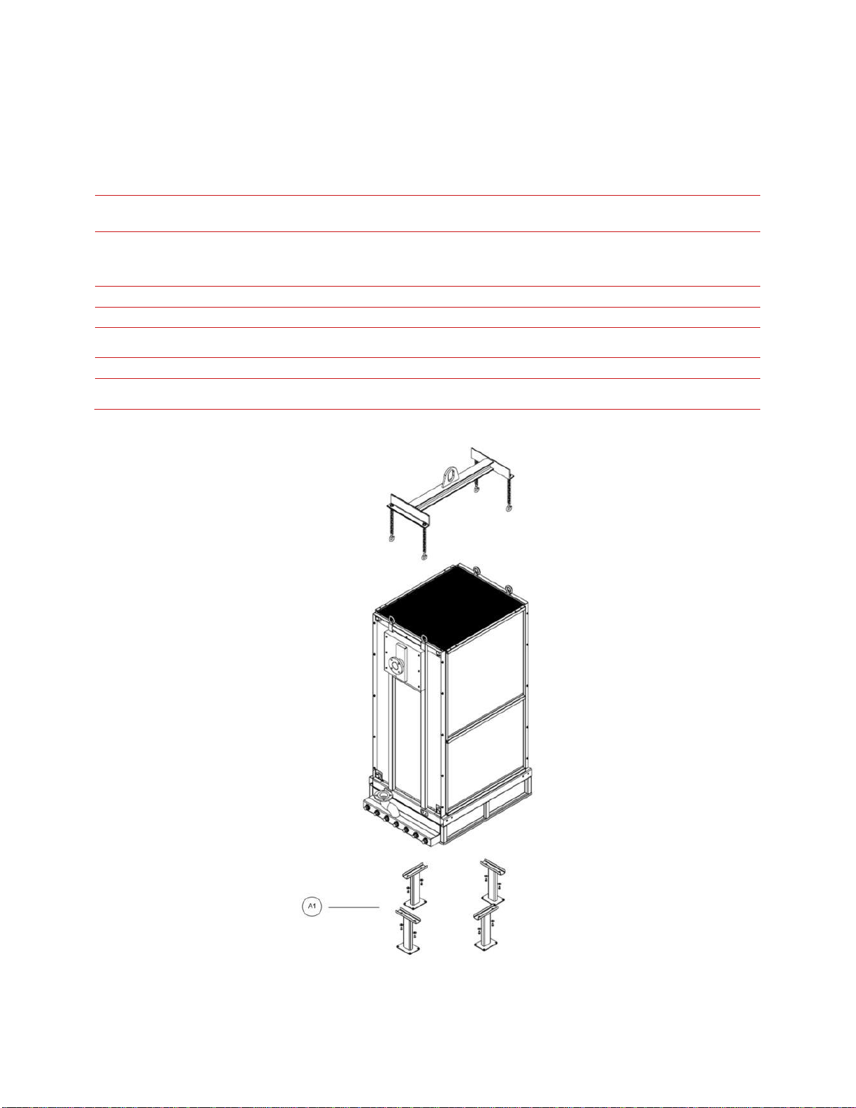
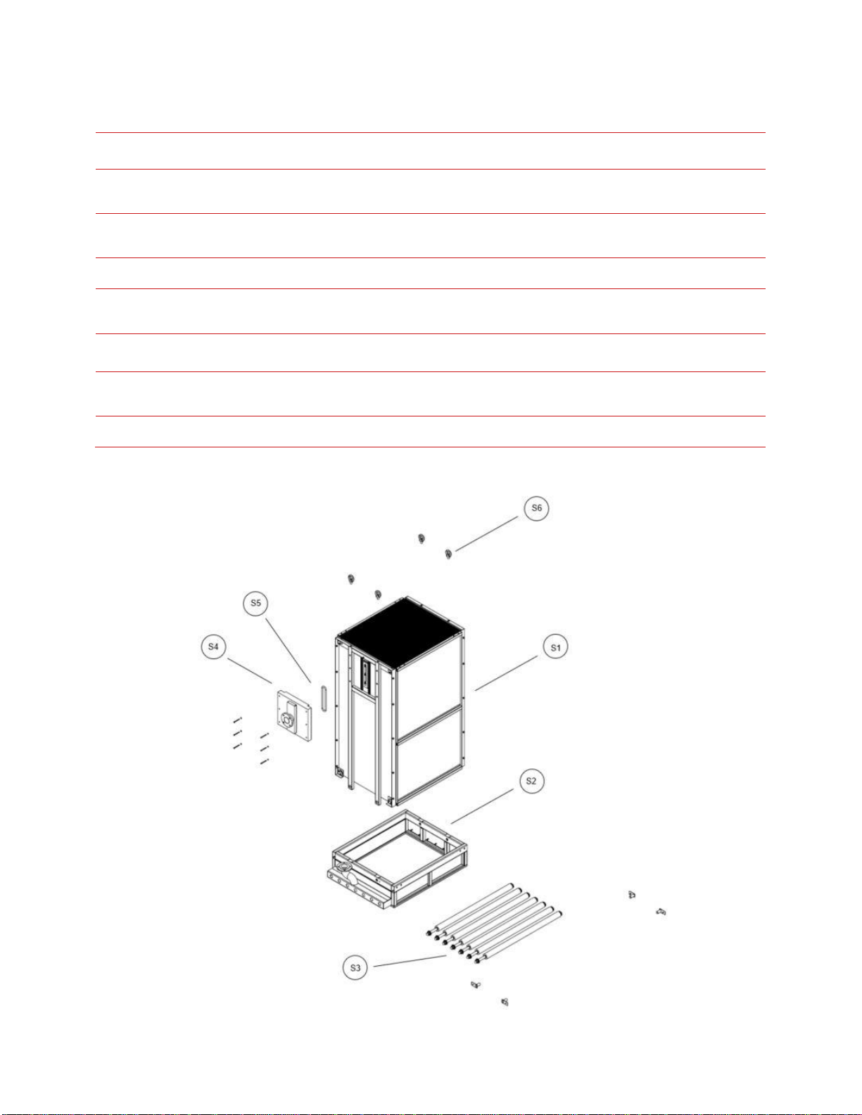
Table 2 and 3 show the available accessories and spare parts for the BIO-CEL® L-1 module.
Table 2. Available Accessories for MICRODYN BIO-CEL® L-1
Position
Part
Number
Drawing
numbers
Accessory
Stainless Steel
Grade
A1
00350115
MN-00200-005-0000
BIO-CEL® L-1 Set of legs
Standard: 1.4301/304 (V2A)
00350116
On request: 1.4571/316Ti or
1.4404/316L (V4A)
-
00200274
-
BIO-CEL® MCP; 25 kg bags
-
-
On request
MN-00200-006-0000
BIO-CEL® L-1 Lifting Tool
-
-
Only drawings
142-91-00
BIO-CEL® L-1 Lifting & Guiding
system
-
-
Only drawings
142-92-00
BIO-CEL® L-1 Wall installation system
-
On request
MN-00200-008-0000
BIO-CEL® L-1 Diffuser cone nut box
spanner
Figure 1. BIO-CEL® L-1 exploded drawing of available accessories
Page 5
5 | 13
Form-No: TI-WW006 // Revision: B // Date: Jul. 5, 18
Table 3. Available Spare Parts for MICRODYN BIO-CEL® L-1
Position
Part
Number
Spare Part
Stainless Steel Grade
S1
00350123
BIO-CEL® L-1 Spare cassette C L-UP150
Standard: 1.4301/304 (V2A)
00350124
On request: 1.4571/316Ti or 1.4404/316L (V4A)
S2
00350125
BIO-CEL® L-1 Base frame including diffusors
Standard: 1.4301/304 (V2A)
00350126
On request: 1.4571/316Ti or 1.4404/316L (V4A)
S3
00350120
BIO-CEL® L-1 Set of 7 tube diffusers
including connectors and sealing
-
S4
00350129
BIO-CEL® L-1 Permeate connector,
Polypropylene DN80, PN6,
including O-Ring
-
S5
On request
O-Ring permeate connector
-
S6
00350127
BIO-CEL® Lifting eye bolts
Standard: 1.4301/304 (V2A)
00350128
On request: 1.4571/316Ti or 1.4404/316L (V4A)
-
00350072
BIO-CEL® Diffuser assembling tool, Torque
wrench with special socket
-
Figure 2. BIO-CEL® L-1 Exploded drawing showing available spare parts
Page 6
6 | 13
Form-No: TI-WW006 // Revision: B // Date: Jul. 5, 18
Replacement of MICRODYN BIO-CEL® L Cassette
The replacement of the BC-L cassette might either be done in the filtration tank or by lifting out the
complete module. In both cases make sure you remove heavy sludge deposits before lifting the module
or the cassette. We do highly recommend to perform an intensive cleaning before starting with
replacement works.
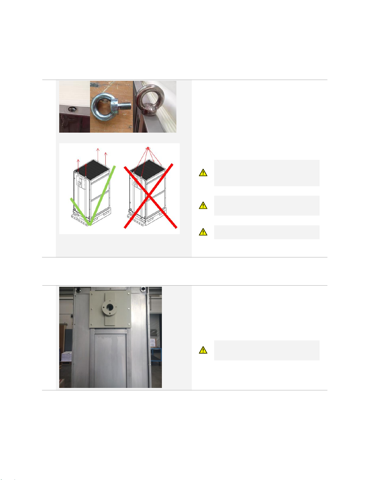
1.
Preparations for lifting
For lifting via crane you have to install the
lifting eye bolts
Use a proper lifting tool for lifting (see also
accessories)
Make sure the module fixation to the tank is
Ioose
Make sure that air and permeate pipework is
disconnected
Make sure the weight of the module is
maximum 1500 kg. Heavy sludge
deposits have to be removed before lifting
module!
Make sure the lifting equipment does not
touch the white membrane sheets when
being attached to the module
Lifting via crane is only allowed in vertical
direction, no lateral pulling is allowed.
Once the module is free of sludge and lifted out of the tank / and the tank is drained completely, continue
with the next steps.
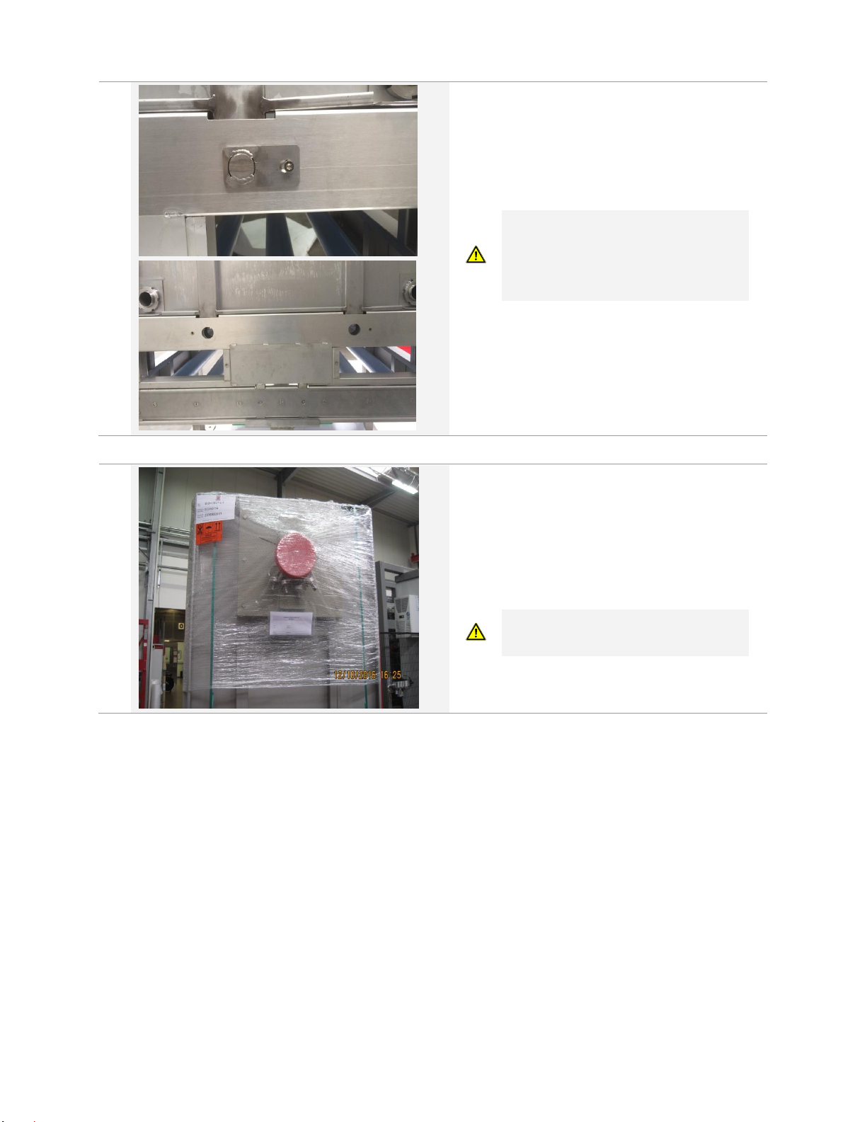
2.
In case you use the existing permeate
connector (and o-ring), you would need to
dismantle it.
Open the screws (M10x90). The screws are
fixed with screw lock, so opening might be
not very easy.
This work should be done by 2 men,
since the permeate connector is very
heavy.
Page 7
7 | 13
Form-No: TI-WW006 // Revision: B // Date: Jul. 5, 18
3.
Open the screws (M6x16) which fix the
connection bolts (which connects the
cassette to the diffuser frame) and remove
the bolts.
The cassette can now be lifted out of the
diffuser frame.
Before installing the new cassette on the
diffuser frame, check the diffuser status.
Depending on their status, recovery or
mechanical diffuser cleaning might be
necessary (please refer to our diffuser
maintenance document TSG-C-WW002).
4.
Prepare the new module as descripted above
(install lifting eye bolts and prepare lifting
tool)
Leave the packaging of the module if
possible till final installation into the tank, this
will minimize the risk of membrane damage
during handling with the lifting tool
Make sure the lifting equipment does not
touch the white membrane sheets when
being attached to the module
Page 8
8 | 13
Form-No: TI-WW006 // Revision: B // Date: Jul. 5, 18
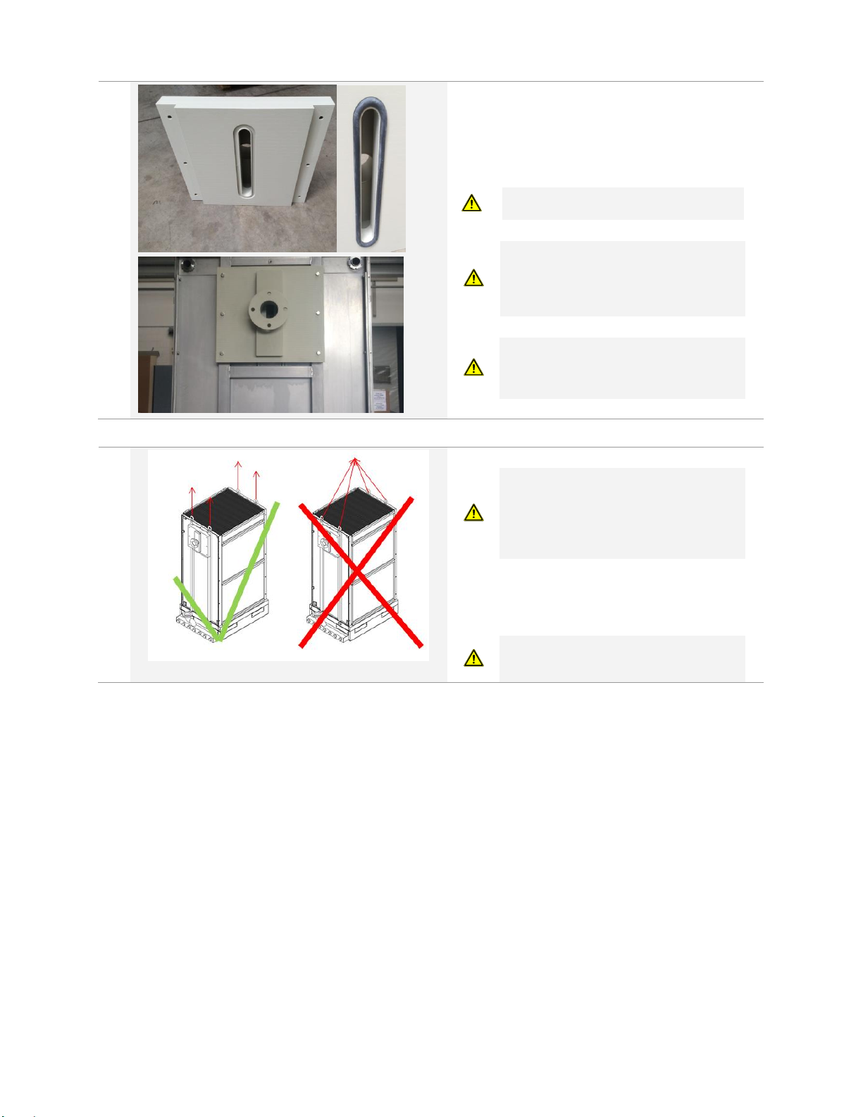
5.
Make sure the o-ring is seated in the groove
correctly.
Mount the permeate connector on the
cassette (open side of permeate channel)
with 6 M10x90 screws.
Do apply some screw lock (Loctite 243)
on the screws before mounting and
torque the screws with 14Nm. Do not
overtighten, otherwise the nuts may be
damaged.
This work should be done by 2 men,
since the permeate connector is very
heavy and the o-ring has to be hold in the
groove.
Do apply some screw lock (Loctite 243)
on the screws before mounting
6.
Before installing the new cassette on the
diffuser frame, check the diffuser status.
Depending on their status, recovery or
mechanical diffuser cleaning might be
necessary (please refer to our diffuser
maintenance document TSG-C-WW002).
Lift the cassette into the diffuser frame.
Please consider the lifting notes above.
Make sure the lifting equipment does not
touch the white membrane sheets when
being attached to the module
Page 9
9 | 13
Form-No: TI-WW006 // Revision: B // Date: Jul. 5, 18
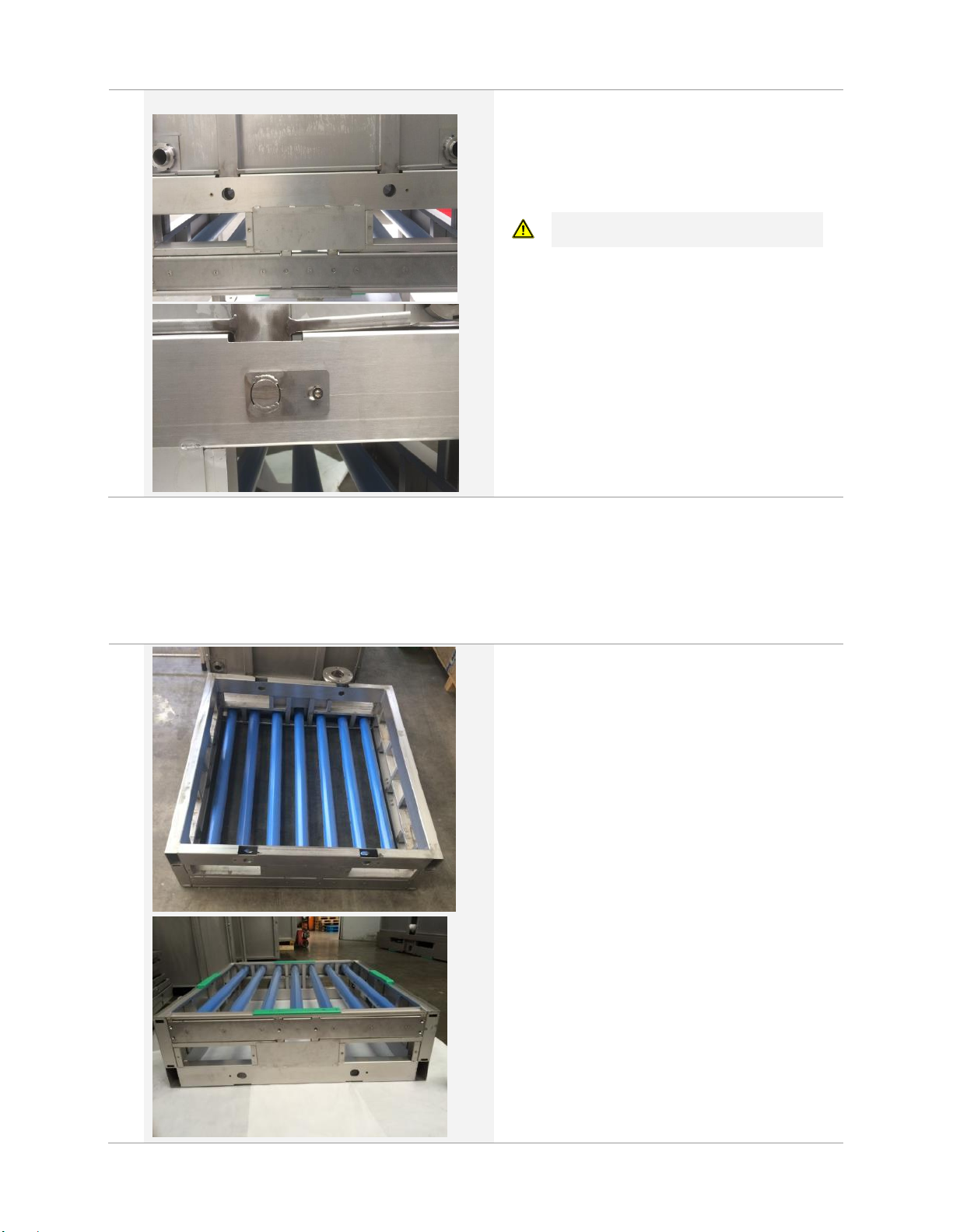
7.
Align the cassette in a way, that the
boreholes of the cassette and the frame do
match.
Put the bolts into the boreholes and fix them
with the screws (M6x16)
Do apply some screw lock (Loctite 243)
on the screws before mounting
The Module is now ready to be installed back again. Before flooding the tank, make sure to remove all
remaining packaging.
Replacement of Diffuser Tubes
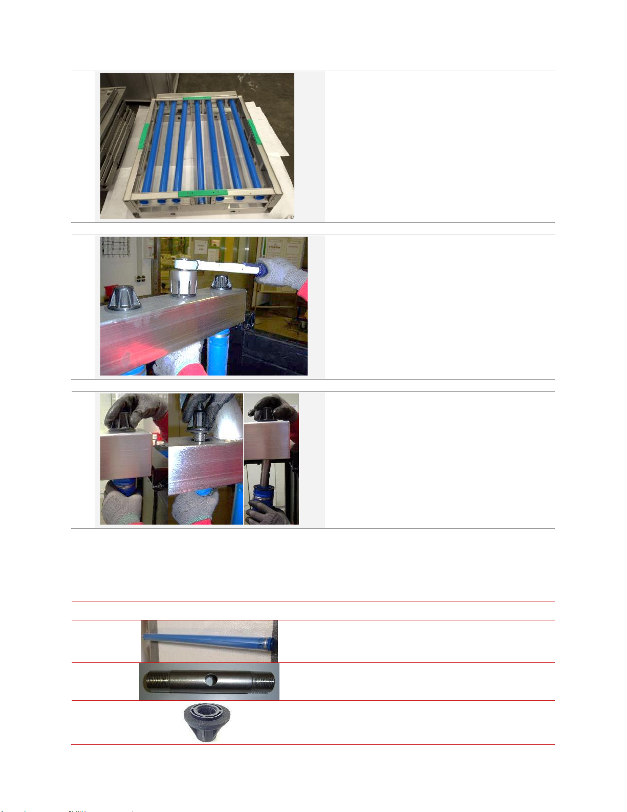
Please proceed first as described in the section above to disconnect the cassette from the diffuser frame.
1.
Before disassembling the module, perform an
intensive cleaning of the module (see
MICRODYN-NADIR O&M Manual)
Remove the cassettes from the frame (as
described above) and turn the base frame on its
head end so that the feet are on the top.
Page 10
10 | 13
Form-No: TI-WW006 // Revision: B // Date: Jul. 5, 18
2.
Open the screws (M6x16) which fix the
counter part of the diffuser tubes and remove
it.
3.
Disassemble the blind cap with the special
socket wrench.
If there are round shaped blind caps (older
systems) use a pipe wrench to remove it..
4.
Remove the double threaded connector with
the blind plug from the opposite side of the
distributor pipe and lift out the diffuser tube.
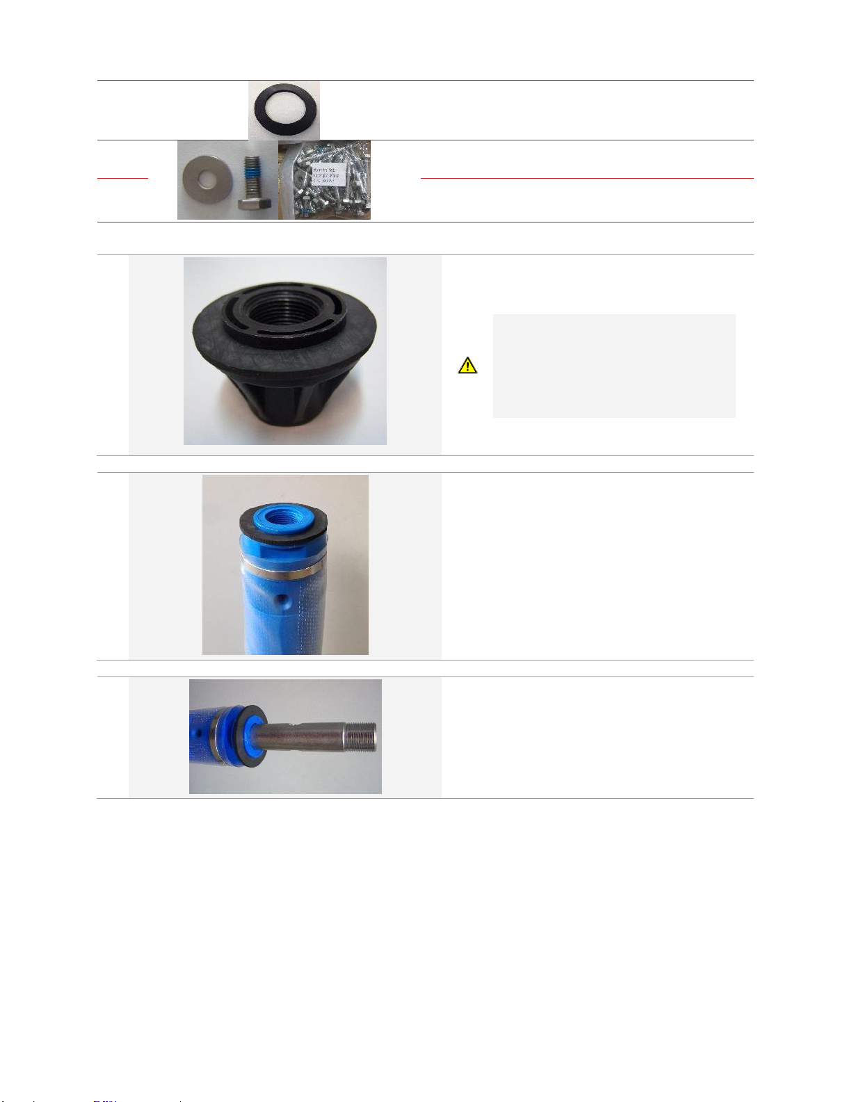
For a diffuser replacement you would need spare part 00350120 (BIO-CEL® L-1 Set of 7 tube diffusers
including connectors and sealing). The Set consists of the parts shown in Table 4.
Table 4: Content of diffuser set
No
Picture
Description
Amount
1 Diffusor tube Length (L)
7
2
Connector for diffusor tube
L
total
= 127 mm
¾“ external thread
7
3 Blind cap incl. flat seal
7
Page 11
11 | 13
Form-No: TI-WW006 // Revision: B // Date: Jul. 5, 18
4 Flat seal
7
5
Washer A 8,4
(from screw set)
3
6
Hex nut M6x16 Tuflok
(from screw set)
3
5.
Check that the flat seal is on the blind plug.
(The plug comes already with a seal!)
The flat seal on the plug is different from
the one you need for the tube (1mm,
thicker). In case, the seal on the plug has
fallen off, make sure you place the right
one on the plug. Place the seal with the
rough side on top (looking to the air
distributor)
6.
Place the flat seal on the diffuser tube.
7.
Screw the double threaded connector into the
diffuser tube.
Page 12
12 | 13
Form-No: TI-WW006 // Revision: B // Date: Jul. 5, 18
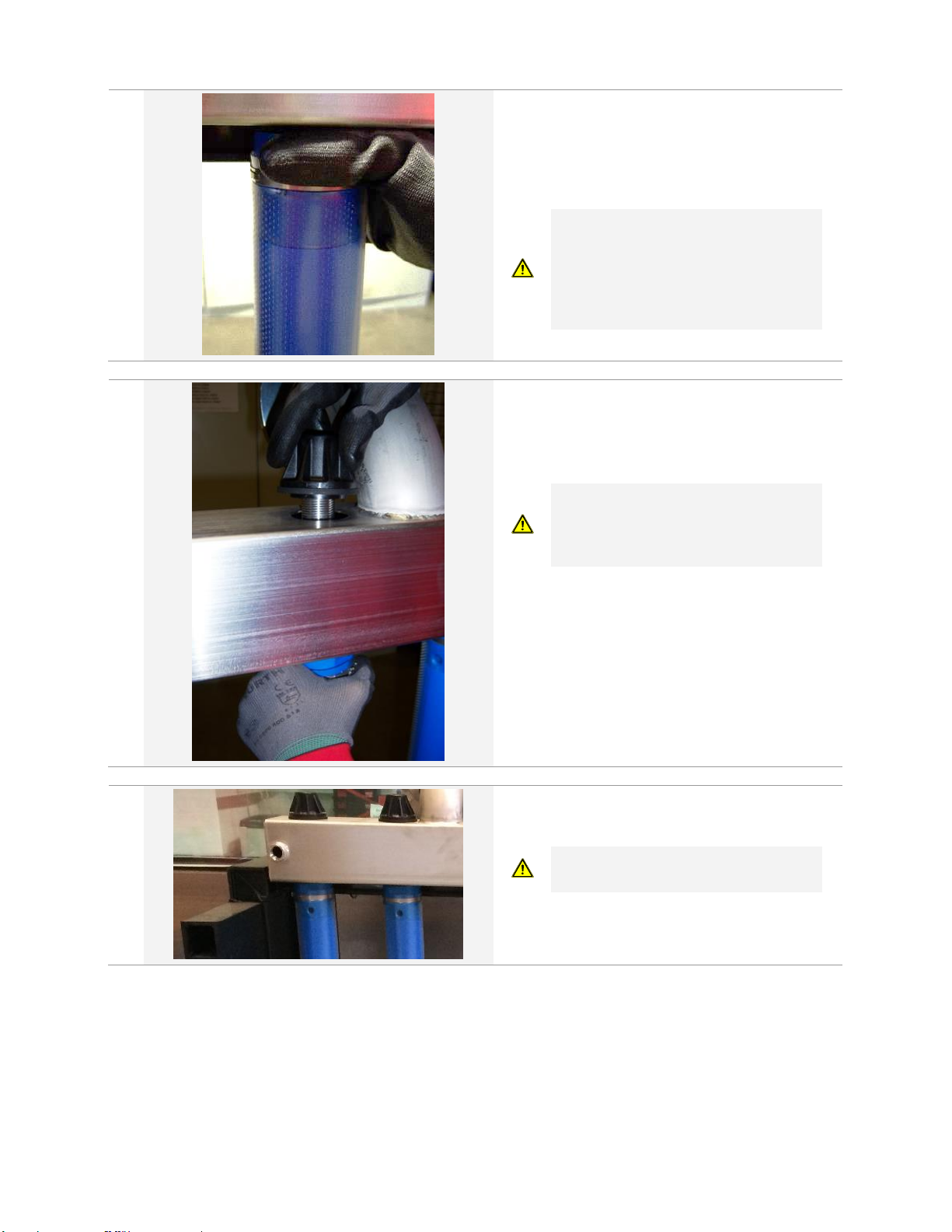
8.
Mount the diffuser tube into the bore hole
from below. Make sure the diffuser is
correctly plugged in the bore hole and the
sealing is pressed against the rectangular
steel pipe.
Make sure that the air distributor is clean
(from out- and inside) before mounting
new diffuser tubes. The surface has to be
absolutely even and free of caves, dents,
sludge and debris like stones, wood
pieces, dust or chips.
9.
Screw the double threaded connector with
the blind cap hand-tight.
Make sure that you have a flat seal on both
sides of the distributor.
Upon screwing do not grab around the
perforated area of the diffusor tube.
Instead please hold the tube only at the
very top, where no perforation is applied.
10.
Adjust the diffuser tubes in a way that the
perforation is at 3 & 9 o’clock before
tightening with the torque wrench.
A correct perforation orientation is
important for proper air distribution.
Page 13
A MANN + HUMMEL Company
Europe
Germany: +49 611 962 6001
Italy: +39 0721 1796201
[email protected]
Americas
USA: +1 805 964 8003
Brazil: +55 11 3378 7500
[email protected]
Asia
China: + 86 592 677 5500
Singapore: +65 6457 7533
[email protected]
Form-No: TDS-WW006 // Revision: C // Date: July 05, 2018
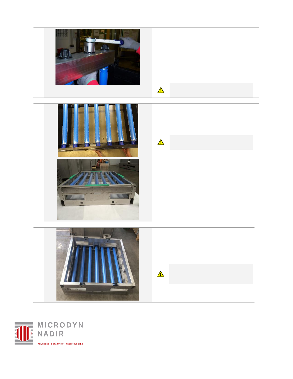
11.
Make sure that the flat seal is correctly
adjusted.
Use the special socket wrench to assemble
the blind cap of the diffusor tube. Make sure
the diffusor tube did not turn and the
perforation is still on the right position (3 & 9
o’clock)
Tighten the diffusors at 30 Nm (265 lbf in).
Tighten the diffusers slowly to avoid the
flat seals squeezing out!
12.
Insert the counter part with the end caps into
the diffusor tubes.
Mount the counter plate with the delivered
M6x16 screws on the diffuser frame.
Do not use the old screws, since screw
lock is gone!
13.
Turn around the diffuser frame and
continue with module assembly as
described above (feet installation is not
mentioned in this document, since there
are different solutions for feet realisation)
Make sure, the diffusers are protected
against direct sunlight and physical
impact!
 Loading...