

User’s Manual
B.Box UPS Series
B.Box LP 500
ADDITIONAL INSTALLATION INFORMATIONS CAN BE FOUND AT:
www.microdowell.net

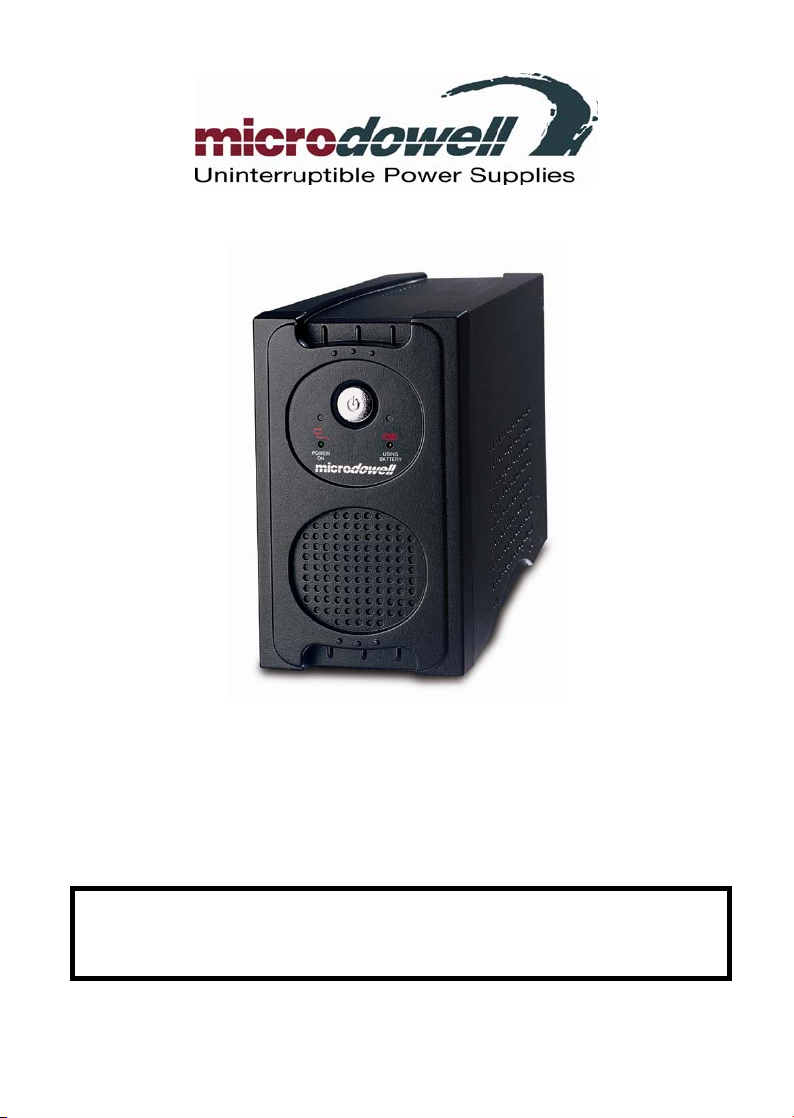
Microdowell Uninterruptible Power Supply
LP500
TABLE OF CONTENTS
SAFETY WARNINGS............ ………………………………………………………….….3
INSTALLING YOUR UPS SYSTEM............………………………………………….…..4
UNPACKING……………………………………………………………………………4
HARDWARE INSTALLATION GUIDE……..………………………………………. 4
BASIC OPERATION.....................................................................…………………….5
FRONT PANEL AND REAR PANEL DESCRIPTION……………………………....5
TROUBLESHOOTING................................................................................................ 7
TECHNICAL SPECIFICATIONS.................................................................................8
DEFINITION FOR ILLUMINATED LED INDICATORS ...............................................9
Thank you for purchasing a Microdowell Product. To enjoy all the features and benefits of this
Uninterruptible Power System (UPS), please read and follow all installation and operation
instructions completely. This UPS is designed to provide guaranteed power protection for
connected electronic equipment. The accompanying Upseye™ software saves data, closes
open applications and automatically shuts down your computer system in an intelligent and
orderly manner.
- 2 -

Microdowell Uninterruptible Power Supply
LP500
SAFETY WARNINGS
(SAVE THESE INSTRUCTIONS)
This manual contains important safety instructions. Please read and follow all instructions
carefully during installation and operation of the unit. Read this manual thoroughly before
attempting to unpack, install, or operate.
This equipment can be operated by any individuals with no previous training.
The socket-outlet shall be installed near the equipment and easily accessible.
During the installation of this equipment, it should be assured that the sum of the leakage
currents of the UPS and the connected loads does not exceed 3.5mA.
Attention, hazardous through electric shock. Also with disconnection of this unit from the
mains, hazardous voltage still may be accessible through supply from battery. The battery
supply should be therefore disconnected in the plus and minus pole at the quick connectors
of the battery when maintenance or service work inside the UPS is necessary.
Do not dispose of batteries in a fire, the battery may explode.
Do not open or mutilate the battery or batteries, released electrolyte is harmful to the skin and
eyes.
- 3 -
Microdowell Uninterruptible Power Supply
LP500
INSTALLING YOUR UPS SYSTEM
UNPACKING
Inspect the UPS upon receipt. The box should contain the following:
(1) UPS Unit; (1) Upseye Software CD-ROM; (1) Serial Interface Cable (DB-9); (1)
Telephone Cable; (2) Power Cord; (1) User Manual;
HARDWARE INSTALLATION GUIDE
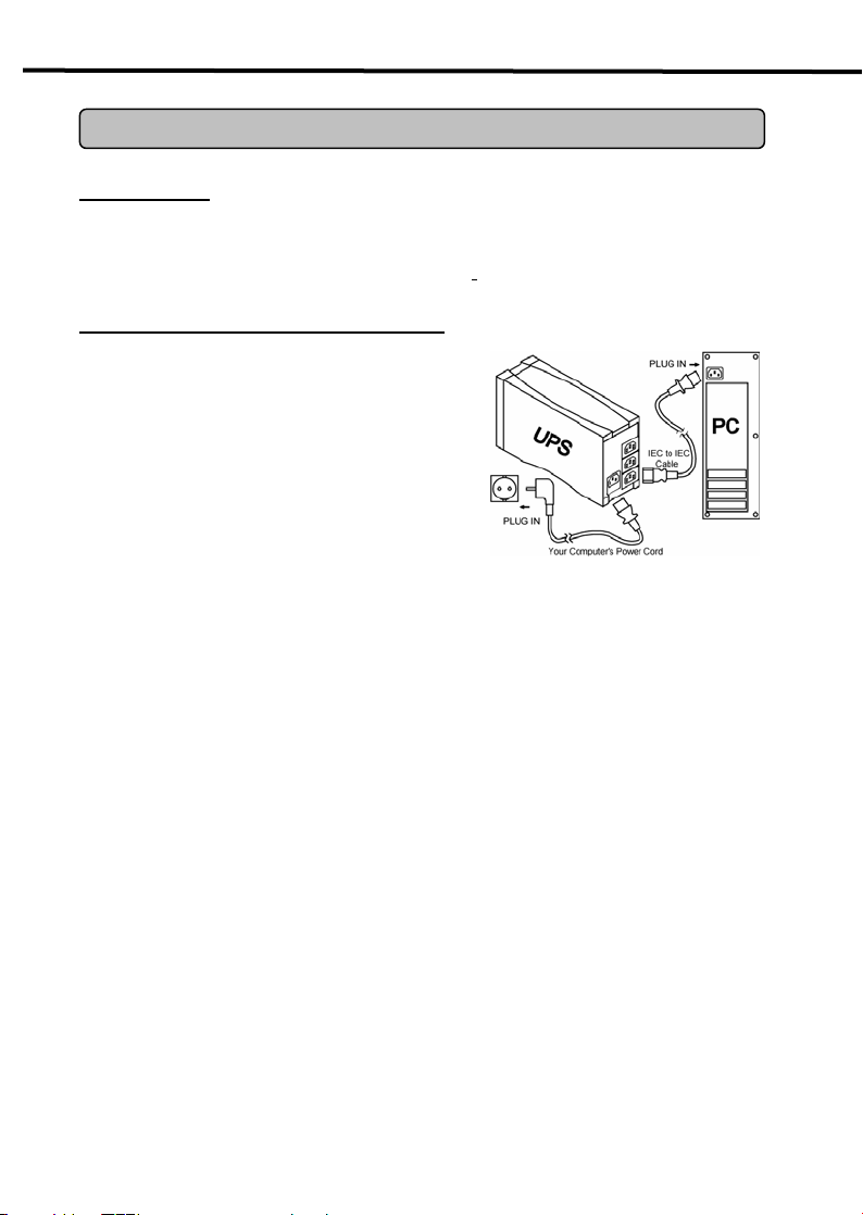
1. Connect the equipment to your UPS outlets.
The IEC to IEC power cords coming with the unit
are used to connect your computer and monitor
to the UPS the UPS. Items such as copiers, laser
printers, vacuums, space heaters, or other large
electrical devices should not be connected to the
UPS. Please make sure that the total loads of
your equipments are less than the maximum total
power load of your UPS.
2. Use your computer power cord to connect the UPS to a wall outlet. Please avoid using
extension cords and adapter plugs. (To maintain optimal battery charge, leave the UPS
plugged in at all times.)
3. Press the UPS power button to turn it on. The
“Power On” indicator will be illuminated in “Green”.
4. Install your optional software and accessories. To use the software, simply connect the
enclosed serial interface cable to the serial port on the UPS and an open serial port on the
computer.
- 4 -
Microdowell Uninterruptible Power Supply
BASIC OPERATION
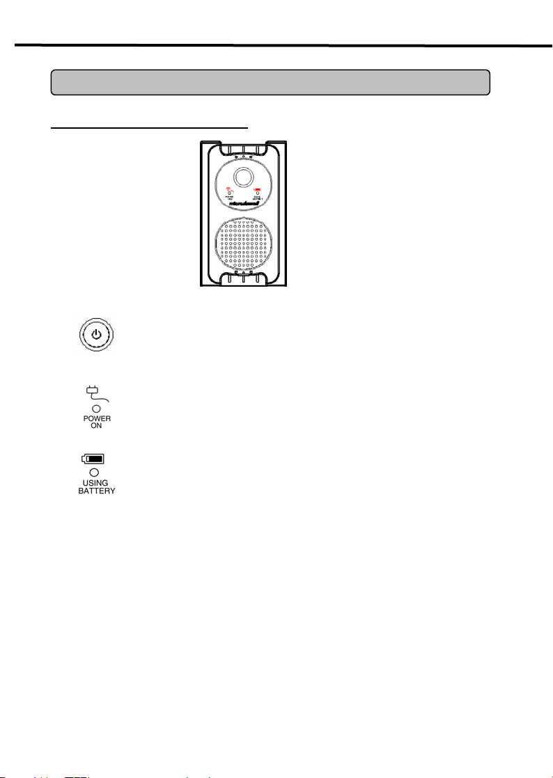
FRONT PANEL DESCRIPTION
Power Switch
Press the power button to turn the UPS ON or OFF
Power On Indicator
This LED is illuminated when the utility condition is normal and the UPS
outlets are providing “clean power”, free of surges and spikes
Battery Indicator
This illuminates during utility failure, indicating that the battery is
supplying power to the battery-power supplied outlets.
LP500
- 5 -
Microdowell Uninterruptible Power Supply
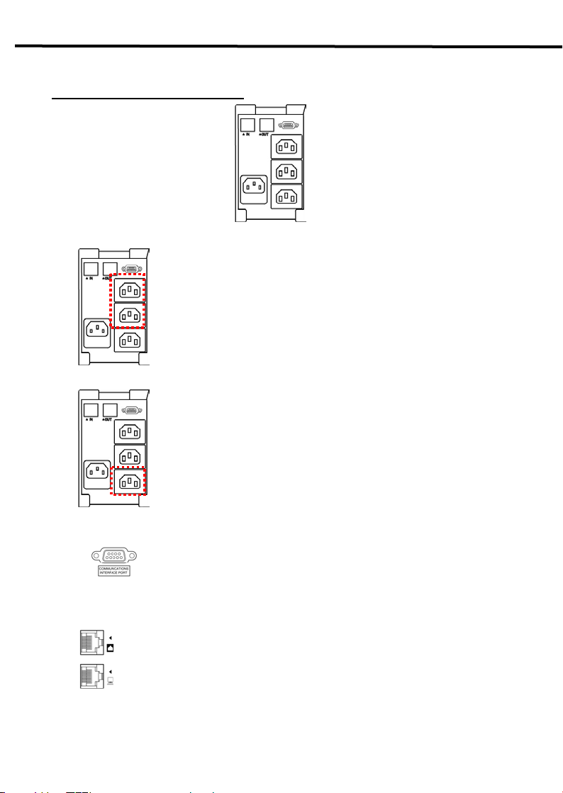
REAR PANEL DESCRIPTION
Battery Backup and Surge Protection Outlets
Surge Protection Outlets
Serial Port to PC
Communication Protection Ports
Provides two battery powered and surge protected outlets for
connected equipment to insure temporary uninterrupted operation
during a power failure and against surges and spikes.
Provides one surge protected only outlet for connected equipment
against surges and spikes.
This port allows connection and communication from the DB-9 serial or USB
port on the computer to the UPS unit. The UPS communicates its status
to the Upseye™ software. This interface is also compatible with the UPS
service provided by Windows 98, Windows ME, Windows 2000
Windows NT, and Windows XP.
Ethernet RJ-45 Network Protection
network cables.
LP500
Ports protect standard
- 6 -

Microdowell Uninterruptible Power Supply
TROUBLESHOOTING
Problem Possible Cause Solution
The UPS does not
perform expected
runtime.
The UPS will not turn on.
Outlets do not provide
power to equipment
Batteries are not fully
charged.
Battery is slightly worn out. Contact Microdowell at
The on/off switch is
designed to prevent damage
by rapidly turning it off and
on.
The unit is not connected to
an AC outlet.
The battery is worn out. Contact Microdowell at
Mechanical problem. Contact Microdowell at
Fuse is blown due to
overload
Batteries are discharged Allow the unit to recharge for at least
Unit has been damaged by a
surge or spike.
Recharge the battery by leaving the
UPS plugged in.
service@microdowell.net
Turn the UPS off. Wait 10 seconds
and then turn the UPS on.
The unit must be connected to a
208/220/230/240 Vac 50Hz outlet.
service@microdowell.net
service@microdowell.net
Turn the UPS off and unplug at least
one piece of equipment. Replace the
blown fuse with a spare one and then
turn the UPS on.
4 hours.
Contact Microdowell at
service@microdowell.net
LP500
- 7 -

Microdowell Uninterruptible Power Supply
LP500
TECHNICAL SPECIFICATIONS
Model LP350 LP500
Capacity (VA) 350VA 500VA
Capacity (Watts) 210W 300W
Input
Input Voltage Range 220-240Vac
Frequency Range 50/60Hz
Output
On Battery Output Voltage Simulated Sine Wave at 230Vac +/-7%
On Battery Output Frequency 50/60 Hz +/- 1%
Overload Protection
Surge Protection and Filtering
Lightning / Surge Protection Yes
Network Protection RJ45 (One In/One Out)
Physical
Total # of UPS Receptacles 2
Maximum Dimensions 23.8cm*8.0cm*13.7cm
Weight 4.4kg 5.0kg
Battery
Sealed Maintenance Free Lead
Acid Battery
Typical Recharge Time 8 Hours
Warning Diagnostics
Indicators
Audible Alarms On Battery, Low Battery, Overload
Environmental
Operating Temperature +32°F to 95°F ( 0°C to 35°C )
Operating Relative Humidity 0 to 95% NON-CONDENSING
Communication
Management
TM
Upseye
Auto-Charger Yes
Auto-Restart
Software Windows 98/ME/2000/NT/XP
On Utility: Fuse, On Battery: Internal Current Limiting
12V / 4AHx1 12V / 4.5AHx1
Power On, Using Battery
Ye s
- 8 -

Microdowell Uninterruptible Power Supply
DEFINITIONS FOR ILLUMINATED LED INDICATORS
Power
On
Using
Battery
Fuse
Alarm
Condition
LP500
On Off Normal Off
Off On Normal Two Beeps
Off On Normal
Off On/Off Blown
Off On/Off
Normal/
Blown
Rapid
Beeps
Two beeps
or rapid
beeps
Long Beep
Normal
Utility Failure- The UPS is providing battery power to
the Battery-Power Supplied outlets.
Utility Failure- The UPS is providing battery power.
The rapid beeps indicate the battery will run out of
charge within a few minutes.
Overload- Occurs in the Full-time Surge Protection
Outlets. Please turn the UPS off and unplug at least
one piece of equipment from the UPS. Replace the
fuse with a spare one then turn the UPS on.
Overload- Occurs in the Battery-power Supplied
Outlets. Turn the UPS off and unplug at least one
piece of equipment from the UPS. Check the fuse
and do the replacement if necessary. Turn the UPS
on.
- 9 -

Microdowell Uninterruptible Power Supply
LP500
Bedienungsanleitung
B.Box UPS Series
B.Box LP 500
ADDITIONAL INSTALLATION INFORMATIONS CAN BE FOUND AT:
www.microdowell.net
- 10 -

Microdowell Uninterruptible Power Supply
LP500
INHALTSÜBERSICHT
SICHERHEITSHINWEISE........................................................................................12
INSTALLATION IHRER USV-ANLAGE ...................................................................13
AUSPACKEN ...................................................................................13
ANLEITUNG FÜR DIE HARDWARE-INSTALLATION .....................13
BASISBETRIEB ....................................................................................................... 14
BESCHREIBUNG DER GERÄTEVORDER- UND –RÜCKSEITE.... 14
STÖRUNGSDIAGNOSE ..........................................................................................16
LEISTUNGSMERKMALE ........................................................................................17
DEFINITIONEN DER LED-LEUCHTANZEIGEN .....................................................18
Herzlichen Glückwunsch dazu, dass Sie sich für ein Produkt von Microdowell entschieden
haben. Um die Eigenschaften und Vorteile dieser unterbrechungsfreien Stromversorgung
(USV-Anlage) nützen zu können, müssen Sie die gesamte Bedienungs- und
Benutzungsanweisung komplett durchlesen und befolgen. Mit dieser USV-Anlage können
Sie die angeschlossenen elektronischen Geräte vor Unregelmäßigkeiten in der
Stromversorgung schützen. Die dazugehörige Upseye™ Software sichert Daten, schließt
offene Anwendungen und schaltet Ihr Rechnersystem automatisch auf intelligente und
geordnete Weise ab.
- 11 -

Microdowell Uninterruptible Power Supply
LP500
SICHERHEITSHINWEISE
(HEBEN SIE DIESE ANLEITUNG AUF)
Dieses Handbuch enthält wichtige Sicherheitsanweisungen. Bitte lesen Sie alle
Anweisungen während der Installation und des Betriebs der Anlage aufmerksam durch und
beachten Sie sie. Lesen Sie dieses Handbuch gründlich durch, bevor Sie die Anlage
auspacken, installieren oder betreiben.
Diese Anlage kann auch Personen, die zuvor nicht geschult wurden, betrieben werden.
Die Ausgangsbuchse muss in der Nähe des zu schützenden Verbrauchers installiert werden
und gut zugänglich sein.
Während der Installation dieses Geräts sollte sichergestellt sein, dass die Summe der
Ableitströme der USV-Anlage und die angeschlossenen Last nicht größer als 3,5mA sind.
Vorsicht, Gefahr durch Stromschlag. Auch nachdem die Anlage vom Stromversorgungsnetz
getrennt ist, sind durch die Batterieversorgung noch gefährliche Spannungen möglich.
Deshalb sollte die Batterieversorgung im Falle von Wartungs- oder Servicearbeiten an der
USV-Anlage am Plus- und am Minuspol an den Batterie-Schnellsteckern abgeklemmt
werden.
Batterien dürfen nie Feuer ausgesetzt werden, da sie explodieren könnten.
Batterien nie öffnen oder zerstören, da freigesetzte Elektrolytflüssigkeit Haut und Augen
angreift.
- 12 -

Microdowell Uninterruptible Power Supply
LP500
INSTALLATION IHRER USV-ANLAGE
AUSPACKEN
Die USV-Anlage nach Erhalt prüfen. In der Packung sollte folgendes enthalten sein:
(1) die USV-Anlage; (1) die Upseye Software; (1) das serielle Schnittstellenkabel (DB-9);
(1) das Telefonkabel; (2) Netzleitungen; (1) das Bedienungshandbuch;
ANLEITUNG FÜR DIE HARDWARE-INSTALLATION
1.Schließen Sie den Verbraucher an die Ausgänge
Ihrer USV-Anlage an. Der Anschluss der
USV-Anlage an Ihren Rechner erfolgt mit dem zum
Lieferumfang gehörenden IEC-IEC-Stromkabel.
Geräte wie Kopierer, Laserdrucker, Staubsauger,
Raumheizer oder andere Elektrogeräte mit hoher
Stromaufnahme sollten nicht an die USV-Anlage
angeschlossen werden. Bitte stellen Sie sicher,
dass die Gesamtlast Ihrer Verbraucher geringer ist
als die maximale Gesamtstromlast der
USV-Anlage.
2.Schließen Sie die USV-Anlage mit Ihrem Rechnerstromkabel an einer Steckdose an. Bitte
verwenden Sie keine Verlängerungskabel und Adapter. (Um eine optimale Batterieladung zu
halten, sollte die USV-Anlage stets in der Steckdose eingesteckt sein).
3.Betätigen Sie den EIN/AUS-Taster, um die USV-Anlage einzuschalten. Dann leuchtet die
„Strom Ein”-Anzeige „grün“ auf.
4.Installieren Sie optionale Software und Zubehör. Um die Software zu verwenden, müssen
Sie einfach das beiliegende serielle Schnittstellenkabel an den seriellen Port der
USV-Anlage und an einen freien seriellen Port am Rechner anschließen.
- 13 -

Microdowell Uninterruptible Power Supply
BASISBETRIEB
BESCHREIBUNG DER GERÄTEVORDERSEITE
EIN/AUS-Schalter
Durch Drücken des Ein/Aus-Schalters kann die USV-Anlage EIN- und
AUSGESCHALTET werden.
Strom EIN-Anzeige
Diese LED leuchtet bei normaler Netzversorgung, wenn die Ausgänge der
USV-Anlage „sauberen Strom“ ohne Stromstöße und Spannungsspitzen
liefern.
Batterieanzeige
Diese Anzeige leuchtet bei Ausfall der Stromversorgung und zeigt an,
dass die batteriegespeisten Ausgänge von der Batterie mit Strom versorgt
werden.
LP500
- 14 -

Microdowell Uninterruptible Power Supply
BESCHREIBUNG DER GERÄTERÜCKSEITE
Batteriegespeiste und vor Stromspitzen schützende Ausgänge
Zwei batteriegespeiste und vor Stromspitzen schützende Ausgänge für
die angeschlossenen Verbraucher, die bei Stromausfall
vorübergehenden unterbrechungsfreien Betrieb sowie Schutz vor
Strom- und Spannungsspitzen liefern.
Vor Stromspitzen schützende Ausgänge
Serieller Port für PC
Kommunikationsport
Einen nur vor Stromspitzen schützenden Ausgang, der die
angeschlossenen Verbraucher vor Strom- und Spannungsspitzen
schützen.
Dieser Port ermöglicht den Anschluss und die Kommunikation zwischen dem
seriellen DB-9-Port bzw. dem USB-Port am Rechner und der USV-Anlage.
Die USV-Anlage meldet ihren Status an die Upseyes™ Software. Diese
Schnittstelle ist auch mit dem von Windows 98/ME/ NT, Windows 2000 und
Windows XP angebotenen gestellten USV-Service kompatibel.
Ethernet RJ-45 Netzwerkschutz Ports schützt Standard-
Netzwerkkabel.
- 15 -
LP500

Microdowell Uninterruptible Power Supply
STÖRUNGSDIAGNOSE
Problem Mögliche Ursache Lösung
Die Autonomie der
USV-Anlage ist kürzer als
erwartet.
Die USV-Anlage lässt
sich nicht einschalten.
Die Ausgänge versorgen
den Verbraucher nicht mit
Strom.
Die Batterien sind nicht voll
aufgeladen.
Die Batterie nähert sich
ihrem Lebensende.
Der Ein/Aus-Schalter hat
einen Schutz, damit es bei
schnellem Ein- und
Ausschalten nicht zu einer
Schädigung kommt.
Die USV-Anlage ist nicht an
den
Wechselspannungsausgang
angeschlossen.
Die Batterie ist verschlissen. Kontaktieren Sie Microdowell unter
Mechanisches Problem. Kontaktieren Sie Microdowell unter
Die Sicherung hat infolge
Überlast ausgelöst
Die Batterien sind entladen. Die USV-Anlage mindestens 4
Die USV-Anlage wurde
durch eine Strom- oder
Spannungsspitze
geschädigt.
Die Batterie aufladen, während die
USV-Anlage am Netz angeschlossen
ist.
Kontaktieren Sie Microdowell unter
service@microdowell.net
Die USV-Anlage ausschalten. 10
Sekunden warten und dann die
USV-Anlage einschalten.
Die Anlage muss an eine Steckdose
mit 208/220/230/240 Vac 50Hz
angeschlossen werden.
service@microdowell.net
service@microdowell.net
Die USV-Anlage ausschalten und
mindestens einen Verbraucher
abtrennen. Die Sicherung ersetzen
dann die USV-Anlage wieder
einschalten.
Stunden aufladen lassen.
Kontaktieren Sie Microdowell unter
service@microdowell.net
LP500
- 16 -

Microdowell Uninterruptible Power Supply
LP500
LEISTUNGSMERKMALE
Modell LP350 LP500
Kapazität (VA) 350VA 500VA
Kapazität (Watt) 210W 300W
Eingang
Eingangsspannungsbereich 220-240Vac
Frequenzbereich 50/60 Hz
Ausgang
Batterieausgangsspannung Simulierte Sinuswelle bei 230Vac +/- 7%
Batterieausgangsfrequenz 50/60 Hz +/- 1%
Überlastschutz
Schutz vor Stromspitzen und
Filterung
Schutz vor Blitz / Stromspitzen Ja
Internetbereit (DSL / Telefon /
FAX / Modem-Schutz)
Physische Merkmale
Gesamtanzahl der
USV-Aufnahmen
Maximale Abmessungen 23,8cm*8,0cm*13,7cm
Gewicht 4,4kg 5,0kg
Batterie
Versiegelte wartungsfreie
Säurebatterie
Typische Aufladezeit 8 Stunden
Warnungen für Diagnose
Anzeigen
Akustische Alarme Batteriebetrieb, Batteriespannung gering, Überlast
Umgebung
Betriebstemperatur +32°F - 95°F (0°C - 35(C)
Relative Luftfeuchtigkeit, Betrieb 0 - 95% OHNE BETAUUNG
Kommunikation
UpseyeTM Software Windows 98/ME/NT/2000/XP
Management
Selbstladung Ja
Automatischer Neustart
Am Netz: Sicherung, in der Batterie: interne Strombegrenzung
RJ45 (One In/One Out)
2
12V / 4AHx1 12V / 4.5AHx1
Strom Ein, Batteriebetrieb
Ja
- 17 -

Microdowell Uninterruptible Power Supply
DEFINITIONEN DER LED-LEUCHTANZEIGEN
Strom
Ein
Ein Aus Normal Aus Normal
Batteriebe
trieb
Sicherung
Alarm
Zustand
LP500
Aus Ein Normal
Aus Ein Normal
Aus Ein/Aus
Durchgebr
annt
Normal/
Aus Ein/Aus
durchgebr
annt
Zwei
Pieptöne
Schnelle
Pieptöne
Zwei
Pieptöne
oder
schnelle
Pieptöne
Langer
Piepton
- 18 -
Netzausfall – Die USV-Anlage versorgt die
batteriegespeisten Ausgänge mit
Batteriestrom.
Netzausfall – Die USV-Anlage liefert
Batteriestrom. Die schnellen Pieptöne
geben an, dass die Batterie in wenigen
Minuten entladen sein wird.
Überlast in den permanent vor
Stromspitzen schützenden Ausgängen. Die
USV-Anlage ausschalten und von der
Wechselspannungsquelle trennen. Die
Sicherung durch eine Ersatzsicherung
austauschen und die USV-Anlage wieder
einschalten.
Überlast in den batteriegespeisten
Ausgängen. Die USV-Anlage ausschalten
und mindestens einen Verbraucher von der
USV-Anlage trennen. Die Sicherung prüfen
und sie gegebenenfalls austauschen. Die
USV-Anlage einschalten.

Microdowell Uninterruptible Power Supply
LP500
Manuale d’uso
B.Box UPS Series
B.Box LP 500
ADDITIONAL INSTALLATION INFORMATIONS CAN BE FOUND AT:
www.microdowell.net
- 19 -

Microdowell Uninterruptible Power Supply
LP500
NORME DI SICUREZZA...........................................................................................21
INSTALLAZIONE DEL GRUPPO DI CONTINUITÀ ..................................................22
INDICE
DISIMBALLO ....................................................................................22
GUIDA ALL'INSTALLAZIONE DELL'HARDWARE............................22
FUNZIONAMENTO DI BASE.................................................................... 23
DESCRIZIONE DEL PANNELLO ANTERIORE E POSTERIORE .... 23
SPECIFICHE TECNICHE .........................................................................................26
DEFINIZIONI PER INDICATORI LED ILLUMINATI ..................................................27
Grazie per aver acquistato un prodotto Microdowell. Per sfruttare al massimo tutte le
potenzialità del gruppo di continuità (UPS), vi preghiamo di leggere e di seguire
attentamente tutte le indicazioni inerenti all'installazione e al funzionamento dell'unità.
Questo UPS è stato ideato per proteggere i vostri apparecchi elettronici da qualsiasi
problema di alimentazione grazie anche al software Upseye™ incluso, che registra i vostri
dati, apre e chiude applicazioni e spegne automaticamente il vostro computer in modo
intelligente e ordinato.
- 20 -

Microdowell Uninterruptible Power Supply
LP500
NORME DI SICUREZZA
(CONSERVARE LE SEGUENTI ISTRUZIONI)
Questo manuale contiene importanti raccomandazioni sulla sicurezza. Si prega di leggere
tutte le istruzioni e di seguirle durante l’installazione e l’utilizzo del gruppo di continuità. Prima
di installare e mettere in funzionamento l’unità, leggere attentamente il presente manuale.
Questa apparecchiatura può venire utilizzata da qualsiasi persona senza una preparazione
specifica.
Assicurarsi che la presa di corrente sia posta vicino all’apparecchiatura in modo da essere
facilmente accessibile.
Durante l’installazione, assicurarsi che la somma delle correnti di dispersione del gruppo di
continuità e dei carichi connessi non superi 3,5 mA.
Attenzione, pericolo di scossa. Anche dopo aver disconnesso l’unità dalla presa elettrica, la
batteria potrebbe fornire ulteriore corrente. Si raccomanda quindi di disconnettere la batteria
al polo positivo e negativo durante la manutenzione o la riparazione dell'unità.
Gettare le batterie nel fuoco potrebbe causarne l’esplosione.
Non aprire o rompere le batterie; l’elettrolito rilasciato è dannoso per la pelle e per gli occhi.
- 21 -

Microdowell Uninterruptible Power Supply
LP500
INSTALLAZIONE DEL GRUPPO DI CONTINUITÀ
DISIMBALLO
Alla consegna accertarsi che la scatola contenga quanto segue:
(1) Unità gruppo di continuità ; (1) Software Upseye; (1) Cavo di interfacciamento seriale
(DB-9); (1) Cavo telefonico; (2) Cavo di alimentazione; (1) Manuale d'uso;
GUIDA ALL'INSTALLAZIONE DELL'HARDWARE
1.Connettere l’apparecchiatura alle prese del
gruppo di continuità. Il cavo di alimentazione IEC /
IEC incluso nell’unità serve per connettere il
computer all’unità. Non connettere articoli come
fotocopiatrici, stampanti laser, aspirapolveri, stufe o
altri dispositivi elettrici di grandi dimensioni.
Assicurarsi che il carico totale dell’apparecchiatura
non superi la potenza totale di carico del gruppo di
continuità.
2. Connettere il gruppo di continuità a una presa a muro tramite il cavo di alimentazione del
computer. Evitare di utilizzare prolunghe e adattatori.
(Per mantenere un livello ottimale di carica, lasciare l’unità sempre collegata alla presa di
corrente).
3. Per avviare il gruppo, premere il pulsante di accensione. L’indicatore “Power On” si
illuminerà di verde.
4. Installare eventuale software opzionale e gli accessori. Per utilizzare il software,
connettere il cavo di interfacciamento seriale alla porta seriale sull’ unità e a una porta
seriale aperta sul computer.
- 22 -

Microdowell Uninterruptible Power Supply
FUNZIONAMENTO DI BASE
DESCRIZIONE DEL PANNELLO ANTERIORE
Accensione
Per accendere e spegnere l’unità, premere il pulsante di accensione.
Indicatore Power On
Questo led si accende quando l’apparecchio è in condizioni normali e le prese
del gruppo di continuità forniscono “energia pulita”, senza sbalzi e picchi.
Indicatore Batteria
Si accende in caso di mancata alimentazione da rete e segnala che l’energia è
fornita dalla batteria.
LP500
- 23 -

Microdowell Uninterruptible Power Supply
DESCRIZIONE DEL PANNELLO POSTERIORE
Backup di batteria e Prese contro gli sbalzi di tensione
Presa contro gli sbalzi di tensione
Porta seriale per PC
Porte di protezione della comunicazione
Fornisce due prese alimentate abatteria e protette contro gli sbalzi di
corrente per alimentare le apparecchiature connesse durante
fluttuazioni di tensione.
Fornisce uno prese protette per alimentare le apparecchiature
connesse durante sbalzi o picchi.
Questa porta permette la connessione e la comunicazione tra la porta
seriale DB-9 o quella USB sul computer e il gruppo di continuità, che
comunica il proprio stato al software Upseye™. Questo interfacciamento è
compatibile anche con il servizio di continuità fornito da Windows 98, ME,
NT, Windows 2000 e Windows XP.
Le porte di protezione Ethernet (RJ-45) proteggono i cavi standard
della rete.
LP500
- 24 -

Microdowell Uninterruptible Power Supply
DIAGNOSTICA
Problema Causa possibile Soluzione
Il gruppo di continuità non
rispetta il runtime
previsto.
Il gruppo di continuità non
si accende .
Impossibile alimentare il
gruppo di continuità
tramite rete elettrica
Batterie non completamente
cariche.
Batterie leggermente
usurate.
L’interruttore on/off previene
i guasti spegnendo e
riaccendendo velocemente
l’unità.
Unità non connessa a una
presa a corrente alternata.
Batteria usurata.
Problema meccanico.
Protezione di sovracorrente
in funzione a causa di un
sovraccarico
Batterie scariche. Ricaricare l’unità per almeno 4 ore
Unità danneggiata da uno
sbalzo o un picco di
tensione.
Ricaricare l’unità collegandola alla
rete di alimentazione.
Contattare Microdowell Systems:
service@microdowell.net
Spegnere il gruppo di continuità e
riaccenderlo dopo 10 secondi.
Connettere l'unità a una presa
208/220/230/240 Vac 50Hz.
Contattare Microdowell Systems:
service@microdowell.net
Contattare Microdowell Systems:
service@microdowell.net
Spegnere l’unità e sconnettere
almeno uno degli apparecchi
collegati. Cambio il prrotezione di
sovracorrente e accendere l'unità.
Contattare Microdowell Systems:
service@microdowell.net
LP500
- 25 -

Microdowell Uninterruptible Power Supply
LP500
SPECIFICHE TECNICHE
Modello LP350 LP500
Capacità (VA) 350VA 500VA
Capacità (Watts) 210W 300W
Caratteristiche elettriche di ingresso
Gamma della tensione 220-240Vac
Gamma della frequenza 50/60 Hz
Caratteristiche elettriche di uscita
Tensione in uscita su batteria Onda sinusoidale simulata a 230Vac +/- 7%
Frequenza in uscita su batteria 50/60 Hz +/- 1%
Protezione sovraccarico Su rete: fusibile
Su batteria: Limitazione corrente interna
Protezione da sovratensione / filtro
Illuminazione / Protezione da
sovratensione
Protezione da sovratensioni per
DSL / telefono / fax / modem
Caratteristiche fisiche
Numero totale prese di corrente 2
Dimensioni massime 23.8cm*8.0cm*13.7cm
Peso 4.4kg 5.0kg
Batterie
Batterie piombo-acido sigillate
senza manutenzione
Tempo medio di ricarica 8 ore
Diagnostica
Indicatori luminosi
Tempo medio di ricarica Batteria, Batteria scarica, Sovraccarico
Specifiche ambientali
Temperatura per il funzionamento 32°F a 95°F ( 0°C a 35°C )
Umidità relativa per il funzionamento 0 a 95% NON CONDENSANTE
Comunicazione
UpseyeTM Software Windows 98/ME/NT/2000/XP
Gestione
Caricamento automatico Si
Riavvio automatico
12V / 4AHx1 12V / 4.5AHx1
RJ45 (Entrata/Uscita)
Power On, Using Battery
Si
Si
- 26 -

Microdowell Uninterruptible Power Supply
DEFINIZIONI PER INDICATORI LED ILLUMINATI
Allarme
Corrente
Utilizzo
batteria
Fusibile
Condizione
LP500
Acceso Spento Normale Spento
Spento Acceso Normale
Spento Acceso Normale Bip rapidi
Spento
Spento
Acceso/
Spento
Acceso/
Spento
Bruciato
Normale/
Bruciato
Due bip
Due bip o
bip rapidi
Bip lungo
Interruzione della rete - L’UPS fornisce corrente da
batteria. I bip rapidi indicano che la batteria si scaricherà
entro pochi minuti.
Sovraccarico alle prese di protezione. Spegnere l’UPS e
scollegare almeno uno degli apparecchi collegati.
Sostituire il fusibile e riavviare l’UPS .
apparecchi collegati. Controllare il fusibile e sostituirlo se
Normale
Interruzione della rete - L’UPS fornisce corrente alle
prese tramite batteria.
Sovraccarico alle prese alimentate dalla batteria.
Spegnere l’UPS e scollegare almeno uno degli
necessario. Riavviare l’UPS.
- 27 -
 Loading...