

Respiratory Pressure Meter
Operating Manual
Federal (USA) law restricts this device to sale by or on the
order of a physician or licensed practitioner.
Micro Direct, Inc.
803 Webster Street
Lewiston, ME 04240
1-800-588-3381
www.mdspiro.com
064-45 US
Issue 1.4
September 2016

Table of Contents
Introduction ......................................................................... 1
Package Contents .............................................................. 2
PUMA PC Software ............................................................ 2
Contraindications ................................ ................................ 4
Warnings and Cautions ...................................................... 4
Indications for Use .............................................................. 5
Operation – mouth pressures (PImax/MIP + PEmax/MEP) . 6
PImax (MIP) Test ................................................................ 7
PEmax (MEP) Test ............................................................. 7
Operation – SNIP (Sniff Nasal Inspiratory Pressure) ........... 8
SNIP Test ........................................................................... 9
Switching Off ...................................................................... 9
Battery Low Voltage Indication ......................................... 10
Battery Replacement ........................................................ 10
Cleaning Instructions ........................................................ 11
External Surfaces of the Spirometer ................................. 11
Sterilization ....................................................................... 11
Cleaning accessories ........................................................ 12
Calibration ........................................................................ 12
Servicing ........................................................................... 14
Product Lifetime ................................................................ 14
Trouble Shooting Information ............................................ 15
Symbols ............................................................................ 22
Specifications ................................................................... 23
Consumables / Supporting Products ................................. 24

1
Introduction
The respiratory pressure meter is a hand held instrument
designed for rapid assessment of inspiratory and expiratory
muscle strength. The unit can measure the maximum
inspiratory and expiratory mouth pressures, MIP and MEP,
and the Sniff Nasal Inspiratory Pressure, SNIP. The result
of each measurement is presented in units of cmH2O gauge
pressure on the liquid crystal display screen.
The unit is easy to operate, battery powered and is supplied
with all the necessary attachments required for immediate
use.
The functionality of the unit may be greatly increased when
connected to a PC running PUMA software. This
application has many advanced features including:
Real time display of pressure/time curves
Overlay of successive curves
Predicted values
Patient database
Incentive display
Maneuver quality check
Maneuver variability measurement

2
Package Contents
The respiratory pressure meter is supplied with the
following items: -
1. Microcomputer unit
2. Rubber mouthpiece (Cat. No. MTH6400)
3. Alkaline PP3 battery
4. Expiration pressure valve assembly (Cat. No. ASS1221)
5. Inspiration pressure valve assembly (Cat. No. ASS1222)
6. Calibration screwdriver
7. Nasal probe sample pack (Cat. No. NPROBE01 x-small;
NPROBE02 small; NPROBE03 medium and
NPROBE04 large)
8. Nasal probe adapter (Cat. No. ASS1091)
9. Mouth pressure bacterial filters (Cat. No. FIL6050)
3 2 4
6 8 2
9
1
SNIP
MIP / MEP
OFF
3 1 7
4
5

3
PUMA PC Software
The functionality of the portable MicroRPM is greatly
increased when connected to the PUMA PC Software, via
an RS232 cable to the Serial Port on the side of the unit.
PUMA PC Software is available as a free download from
http://www.carefusion.co.uk/our-products/respiratorycare/cardio-pulmonary-diagnostics/pulmonary-functiontesting/spirometers/spirometry-software-and-firmwaredownloads.
The PUMA PC Software is unique, user friendly multi
windows platform for the performance, storage and analysis
of the respiratory muscle strength measurement of PImax or
MIP (Maximum Inspiratory Pressure), PEmax or MEP
(Maximum Expiratory Pressure) and SNIP (Sniff Nasal
Inspiratory Pressure). In addition, PUMA PC Software offers
the user features such as live graphical displays, predicted
values, printing formats, incentives, trends, post medication
or exercise comparisons and additional fatigue indicators.

4
Note: The Respiratory Pressure Meter should only be
connected to a computer that is manufactured in
accordance with EN 60601-1.
Note: Keep the PC out of reach of the patient at all times.
Contraindications
Pathological conditions resulting in relatively large
pressure swings in the abdomen or thorax.
Aneurisms
Uncontrolled hypertension
Urinary incontinence
Warnings and Cautions
The following terms are used as follows in this manual
Caution: Possibility of injury or serious damage
Warning: Conditions or practices that could result in
personal injury
Please Note: Important information for avoiding damage to
the instrument or facilitating operation of the instrument.
Note: The device should be used by qualified personnel
trained in lung function testing.
CAUTION: Read the manual before use.
CAUTION: For batteries, do not attempt to charge, connect
improperly, or dispose of in fire as there is possibility of
leakage or explosion. Follow manufacturer’s
recommendation for proper disposal.

5
WARNING: The instrument is not suitable for use in the
presence of explosive or flammable gases, flammable
anesthetic mixtures or in oxygen rich environments.
CAUTION: Bacterial filters are single patient use. If used on
more than one patient, there is a risk of cross-infection.
Repeated use may increase air resistance and lead to an
incorrect measurement.
PLEASE NOTE: The product and the battery you
have purchased should not be disposed of as
unsorted waste. Please utilize your local recycling
facility for the disposal of this product.
PLEASE NOTE: Degree of protection against Ingress of
Water is IPX0.
CAUTION: When you connect the Respiratory Pressure
Meter to other equipment, always make sure that the whole
combination complies with the international safety standard
IEC 60601-1 for medical electrical systems. During
measurements, connect the Respiratory Pressure Meter
only to computers that comply with IEC/EN 60601-1 /
ANSI/AAMI ES60601-1:2005.
Indications for Use
The MicroRPM (Respiratory Pressure Meter) is a hand held
diagnostic instrument designed for rapid assessment of
inspiratory and expiratory muscle strength. The unit can
measure the maximum inspiratory and expiratory mouth
pressures, MIP and MEP, and the Sniff Nasal Inspiratory

6
Pressure, SNIP. The system is intended for use with adults
and pediatric patients over the age of 3 years in hospitals,
physician offices, laboratories and occupational health
testing environments.
Operation – mouth pressures (PImax/MIP +
PEmax/MEP)
Insert the battery into the battery compartment at the rear of
the MicroRPM.
Fit the required pressure valve assembly (‘Inspiratory’ for
PImax (MIP), ‘Expiratory’ for PEmax (MEP)) into the
MicroRPM; insert a new bacterial filter into the pressure
valve assembly and then the rubber flanged mouthpiece
onto the bacterial filter as shown below.

7
PImax (MIP) Test
Slide the MicroRPM switch from the “off” position to the
MIP/MEP position, while applying no pressure to the
mouthpiece. Rotating segments will be displayed while the
unit performs an auto-zero function.
When the MicroRPM is ready a ‘beep’ will be heard and ‘0’
will be displayed.
To perform the test, instruct the subject to insert the
mouthpiece into the mouth, ensuring the flange is positioned
over the gums and inside the lips, while the ‘bite blocks’ are
between the teeth.
The subject should then exhale to RV (Residual Volume),
lungs empty, then perform a ‘Mueller’ maneuver, a forced
inhalation against the MicroRPM with as much effort as
possible for as long as possible (minimum of 2 seconds).
The display will report the result, the maximum average
inspiratory pressure sustained over a 1 second period of the
test, in centimeters of water (cmH20). Ideally, the subject
should repeat this test three times to establish the best
value.
PEmax (MEP) Test
Slide the MicroRPM switch from ‘Off’ to ‘MIP/MEP’, while
applying no pressure to the mouthpiece. Rotating segments
will be displayed while the unit performs an auto-zero
function.
When the MicroRPM is ready a ‘beep’ will be heard and ‘0’
displayed.
To perform the test, instruct the subject to insert the
mouthpiece into the mouth, ensuring the flange is positioned

8
over the gums and inside the lips, while the ‘bite blocks’ are
between the teeth.
The subject should then inhale to TLC (Total Lung
Capacity), lungs full, then perform a ‘Valsalva’ maneuver, a
forced exhalation against the MicroRPM with as much effort
as possible for as long as possible (minimum 2 seconds).
The display will report the result, the maximum average
expiratory pressure sustained over a 1 second period of the
test, in cmH2O. Ideally, the subject should repeat this test
three times to establish a best value.
To repeat either the PImax or PEmax tests, the MicroRPM
must first be returned to the ‘Off’ position.
Operation – SNIP (Sniff Nasal Inspiratory Pressure)
Insert the battery into the rear of the MicroRPM.
Fit the nasal probe adapter into the MicroRPM and then
attach the correct size nasal probe, as shown below.
Nasal probe
2
Microcomputer unit
Nasal plug
adapter

9
The correct size (1-4) can be determined by fitting a nasal
probe to the unit then firmly inserting the nasal probe into a
nostril. Instruct the subject to block the open nostril with a
finger and then to attempt a sniff. The correct nasal probe
has been selected once there is not leakage around the
nasal probe.
SNIP Test
Slide the MicroRPM switch from ‘Off’ to ‘SNIP’, while
applying no pressure to the nasal probe. Rotating segments
will be displayed while the unit performs an auto-zero
function.
When the MicroRPM is ready a ‘beep’ will be heard and ‘0’
displayed.
To perform the test, instruct the subject to insert the chosen
nasal probe firmly into a nostril, while ensuring the other
nostril remains open throughout the test.
The subject should then breathe normally and at the end of
a normal tidal expiration, FRC (Functional Residual
Capacity), be instructed to perform a short, sharp voluntary
sniffing maneuver with as much effort as possible.
The display will report the result, the peak inspiratory nasal
pressure, in cmH2O.
On subsequent tests, the MicroRPM will continue to display
the highest SNIP value, overwriting previous values. Ideally,
the subject should repeat this test 10-15 times to determine
the highest value.
Switching Off
The MicroRPM is switched off by sliding the switch back to
the ‘Off’ position.

10
Battery Low Voltage Indication
The battery level is checked when the unit is switched on.
When the battery is nearly exhausted ‘bAt’ is displayed
before the auto-zero procedure begins. The unit may be
used when this occurs provided the test is performed
immediately. The battery should be replaced as soon as
possible.
When the battery is completely exhausted, the unit will beep
twice and turn itself off immediately after turning on.
Note: If the respiratory pressure meter is not used for long
periods, the battery should be removed to prevent damage
to the instrument by possible leakage.
Battery Replacement
Locate the sliding cover situated on the rear of the unit,
toward the bottom of the device.
Place your thumb over the round thumb indent, press gently
and slide the cover to the right to remove it from the unit.
Lift the old battery out and holding the battery terminal by
the plastic body, pull it off the old battery.
Plug the new battery into the battery terminal, taking care
that the correct polarity is observed.
Push the battery back into the battery holder and replace
the battery cover onto the guides. Slide the battery cover to
the left until it is fully in place.
Note: Please remove the battery if the meter is likely to be
unused for some time.

11
CAUTION: Do not open the battery cover when the device
is turned on.
CAUTION: The operator should not touch the contacts of
the battery and the patient at the same time.
Please Note: Dispose of the waste battery in accordance
with your local waste battery regulations.
Cleaning Instructions
Disinfection of contaminated parts is only effective after
careful preliminary cleaning. Please follow the
manufacturer’s instructions for the solution you are using.
The device must not be wiped with any aqueous solutions
and must not be exposed to solvents e.g. alcohol, chloride
solutions, as there are electronic components inside that will
be permanently damaged.
CAUTION: Switch off the device before cleaning.
External Surfaces of the Spirometer
CAUTION: Do not attempt to wash or immerse the
Respiratory Pressure Meter in water or cleaning fluid, as
there are electronic components inside that will be
permanently damaged.
The external surfaces of the pressure meter and the
inspiratory and expiratory valves may be wiped with a
disinfection wipe such as a Protex wipe (order #48-70). This
should be performed after every patient.
Sterilization
The rubber flanged mouthpieces can be sterilized using
ETO – Ethylene Oxide Sterilization.

12
Cleaning accessories
The MicroRPM unit is protected from contamination by the
Bacterial Filter (36-FIL6050) during mouth pressures
measurements.
The Rubber Flanged Mouthpiece (MTH6400), the Expiratory
and Inspiratory Pressure Valve Assembly (ASS1221 and
ASS1222) and the Nasal Probes (NPROBE01, NPROBE02,
NPROBE03, NPROBE04), however, may be immersed in a
cold sterilizing solution. Rinse thoroughly and allow to dry
before reassembly.
Important note: Used mouthpieces and Nasal Probes,
which are not sterilized, must be disposed of immediately
after each use.
If there are changes on the material surfaces (cracks,
brittleness) the respective parts must be disposed of.
Calibration
Calibration is factory set and should remain stable
indefinitely. However, calibration may be checked by
connecting the device to a manometer as shown below:
Manometer
cm H O
2
0
2
1
3
6
4
5
8
7
9
Syringe
10
Connecting
line
Female
Luer
T Piece
Nasal plug
adapter

13
Turn the respiratory pressure meter on to the SNIP position.
Very slowly fill the syringe until a negative pressure of
between 200 and 300 cmH2O is obtained on the
manometer.
The reading on the respiratory pressure meter should be
within 3% of the manometer reading.
If adjustment is required, the following procedure must be
followed.
The calibration may only be adjusted in a positive direction
as the meter monitors the peak pressure value. Therefore,
if the respiratory pressure meter reading was greater than
the manometer reading the calibration screw must be turned
anti-clockwise a few turns before calibration is attempted.
Serial
port
Calibration
screw
Connect the respiratory pressure meter to the manometer
as previously shown. Fill the syringe to obtain the required
negative pressure and turn the calibration screw slowly in a
clockwise direction until the same value is displayed on the
meter.

14
Servicing
If your unit requires service or repair, please see page 24
for contact details.
A full service manual including circuit diagrams and parts list
is available on request.
Product Lifetime
The MicroRPM is designed for a product lifetime of five
years.

15
Trouble Shooting Information
Should you encounter problems operating your MicroRPM
unit, please consult the table below:
Problem
Possible Cause
Solution
Unit will not turn
on
Battery is
spent/discharged
Replace the
battery
Slide switch
connection
Return unit for
servicing
Display shows
reading before
test has been
performed
Internal tubing to
pressure sensor
kinked
Return unit for
servicing
Safety Designation per IEC 60601-1
Type of protection against electrical
shock
Internally powered
Equipment
Degree of protection against
electrical shock
Type B applied part
Power Equipment
Battery
Battery Life
2000 tests
Degree of Electrical connection
between equipment and patient
Equipment designed
as non-electrical
connection to the
patient
Degree of mobility
Portable
Mode of operation
Continuous
Classifications according to IEC 60601-1
Respiratory Pressure Meter
Applied part, type B
WARNING: No modification of this equipment is allowed.

16
WARNING: Do not connect devices that are not specified
as part of the system
Note: When you connect other equipment to the unit,
always make sure that the whole combination complies with
the international safety standard IEC 60101-1 for medical
electrical systems. During measurements, connect the
MicroRPM only to computers that comply with IEC/EN
60601-1 / ANSI/AAMI ES60601-1:2005.
WARNING: The user must not touch any conductive parts
and the patient at the same time.
Electromagnetic Compatibility (EMC) to EN606011:2007
WARNING: Use of portable phones or other radio frequency (RF)
emitting equipment near the system may cause unexpected or
adverse operation.
The MicroRPM has been tested to EN60606-1-2:2007, regarding
the ability to operate in an environment containing other
electrical/electronic equipment (including other medical devices).
The purpose of this testing is to ensure that the MicroRPM is not
likely to adversely affect the normal operation of other such
equipment and that other such equipment is not likely to adversely
affect the normal operation of the MicroRPM.
Despite the testing of the MicroRPM that has been undertaken,
normal operation of the MicroRPM can be affected by other
electrical/electronic equipment and portable and mobile RF
communications equipment.
As the MicroRPM is medical equipment, special precautions are
needed regarding EMC (electromagnetic compatibility).
It is important that the MicroRPM is configured and installed /put
into service, in accordance with the instructions/guidance provided
herein and is used only in the configuration as supplied.

17
Changes or modifications to the MicroRPM may results in
increased emissions or decreased immunity of the MicroRPM in
relation to EMC performance.
The MicroRPM should be used only with the accessories (RS232
cables) supplied (which are referenced in the accessories section
of this manual). None of the MicroRPM cables should be
extended in length by the user.
If any cables are extended by the user or non-approved
accessories are used, this may result in an increased level of
emissions or decreased level of immunity, in relation to the
MicroRPM’s EMC. None of the MicroRPM accessories should be
used with other devices, as this may result in an increased level of
emissions or decreased level of immunity, in relation to the other
devices’ EMC.
The MicroRPM has a minimum basic performance – The
respiratory pressure readings on the product must remain within a
tolerance of +/- 3%, and the unit firmware must not cease
responding. Warning: In the vent the product is operated in the
presence of significant electromagnetic fields (particularly in the
frequency range 40-60MHz) while in the PC connected mode,
ensure the results on the unit and PC are the same. If the results
differ, then relocating the product away from sources of
interference should resolve any issue.
WARNING: The MicroRPM should not be used adjacent to or
stacked with other equipment. If adjacent or stacked use with
other equipment is necessary, the MicroRPM and the other
equipment should be observed/monitored, to verify normal
operation in the configuration in which it will be used.

18
Guidance and Manufacturer’s Declaration – Electromagnetic Emissions
The MicroRPM is intended for use in the electromagnetic environment specified
below. The customer or the user of the MicroRPM should assure that it is used in
such an environment
Emission Test
Compliance
Electromagnetic Environment Guidance
RF emissions
CISPR 11
Group 1
The MicroRPM uses RF energy only for
its internal function. Therefore, its RF
emissions are very low and are not likely
to cause any interference in nearby
electronic equipment
RF emissions
CISPR 11
Group B
The MicroRPM is suitable for use in all
establishments, including residential
establishments and those directly
connected to the public low-voltage
power supply network that supplies
buildings used for domestic purposes
Harmonic emissions
IEC61000-3-2
Not Applicable
Voltage fluctuations /
flicker emissions
IEC61000-3-3
Not Applicable
Guidance and Manufacturer’s Declaration – Electromagnetic Immunity
The MicroRPM is intended for use in the electromagnetic environment specified
below. The customer or the user of the MicroRPM should assure that it is used in
such an environment.
Immunity Test
IEC 60601 Test
Level
Compliance
Level
Electromagnetic
Environment -
Guidance
Electrostatic
discharge (ESD)
IEC61000-4-2
+/- 6 kV contact
+/- 8 kV air
+/- 6 kV contact
+/- 8 kV air
Floors should be
wood, concrete or
ceramic tile. If floors
are covered with
synthetic material, the
relative humidity
should be at least
30%
Electrical fast
transient / burst
IEC61000-4-4
+/- 2 kV for power
supply lines
+/- 1 kV for input /
output lines
+/- 1 kV for
input/output lines
Mains power quality
should be that of a
typical commercial or
hospital environment
Surge
IEC61000-4-5
+/- 1 kV line(s) to
line(s)
+/- 2 kV line(s) to
earth
Not Applicable
Mains power quality
should be that of a
typical commercial or
hospital environment

19
Voltage dips,
short
interruptions and
voltage
variations on
power supply
input lines
IEC61000-4-11
< 5% UT
(> 95% dip in UT)
For 0.5 cycle
40% UT
(60% dip in UT) for
5 cycles
70% UT
(30% dip in UT) for
25 cycles
<5% UT (> 95%
dip in UT) for 5 s
Not Applicable
Mains power quality
should be that of a
typical commercial or
hospital environment.
If the user of the
MicroRPM requires
continued operation
during power mains
interruptions, it is
recommended that
the MicroRPM be
powered from an
uninterruptible power
supply or a battery
Power frequency
(50/60 Hz)
Magnetic field
IEC61000-4-8
3 A / m
3 A / m
Power frequency
magnetic fields should
be at levels
characteristic of a
typical location in a
typical commercial or
hospital environment.
NOTE UT is the a.c. mains voltage prior to application of the test level.
Guidance and Manufacturer’s Declaration – Electromagnetic Immunity
The MicroRPM is intended for use in the electromagnetic environment specified
below. The customer or the user of the MicroRPM should assure that it is used in
such an environment.
Immunity
Test
IEC 60601
Test Level
Compliance
Level
Electromagnetic Environment Guidance
Portable and mobile RF
communications equipment should
be used no closer to any part of the
MicroRPM, including cables, than
the recommended separation
distance calculated from the
equation applicable to the frequency
of the transmitter.

20
Conducted RF
IEC61000-4-6
Radiated RF
IEC61000-4-3
3 Vrms 150
kHz to 80
MHz
3 V/m 80
Mhz to 2.5
Ghz
3 V
3 V/m
Recommended separation
distance (d)
d = 1.2√P
d = 1.2√ P 80 MHz to 800 MHz
d = 2.3√ P 800 MHz to 2.5 GHz
Where P is the maximum output
power rating of the transmitter in
watts (W) according to the
transmitter manufacturer and d is
the recommended separation
distance in meters (m).
Fields strengths from fixed RF
transmitters, as determined by an
electromagnetic site survey,
a
should be less than the compliance
level in each frequency range. b
Interference may occur in the
vicinity of equipment marked with
the following symbol:
NOTE 1 At 80 MHz and 800 MHz, the higher frequency range applies.
NOTE 2 These guidelines may not apply in all situations. Electromagnetic
propagation is affected by absorption and reflection from structures, objects and
people.
a
Field strengths from fixed transmitters, such as base stations for radio (cellular /
cordless) telephones and land mobile radios, amateur radios, AM and FM radio
broadcast and TV broadcast cannot be predicted theoretically with accuracy. To
assess the electromagnetic environment due to fixed RF transmitters, an
electromagnetic site survey should be considered. If the measured field strength in
the location in which the MicroRPM is used exceeds the applicable RF compliance
level above, the MicroRPM should be observed to verify normal operation. If
abnormal performance is observed, additional measures may be necessary, such as
re-orientating or relocating the MicroRPM
b
Over the frequency range 150 kHz to 80 MHz, field strengths should be less than 3
V / m
21
Recommended separation distances between portable and mobile RF
communications equipment and the MicroRPM
The MicroRPM is intended for use in an electromagnetic environment in which
radiated RF disturbances are controlled. The customer or the user of the MicroRPM
can help prevent electromagnetic interference by maintaining a minimum distance
between portable and mobile RF communications equipment (transmitters) and the
MicroRPM as recommended below, according to the maximum output power of the
communications equipment.
Rated Maximum
Output Power of
Transmitter in
Watts (W)
Separation Distance in Meters (m) according to
Frequency of Transmitter
150 KHz to 80
MHz
d = 1.2 √ P
80 MHz to 800
MHz
d = 1.2 √ P
800 MHz to 2.5
GHz
d = 2.4 √ P
0.01
0.12
0.12
0.23
0.1
0.38
0.38
0.73
1
1.2
1.2
2.3
10
3.8
3.8
7.3
100
12
12
23
For transmitters rated at a maximum output power not listed above, the
recommended separation distance d in meters (m) can be estimated using the
maximum output power rating of the transmitter in Watts (W) according to the
transmitter manufacturer.
NOTE 1 At 80 MHz and 800 MHz, the separation distance for the higher frequency
range applies.
NOTE 2 These guidelines may not apply in all situations. Electromagnetic
propagation is affected by absorption and reflection from structures objects and
people.
22
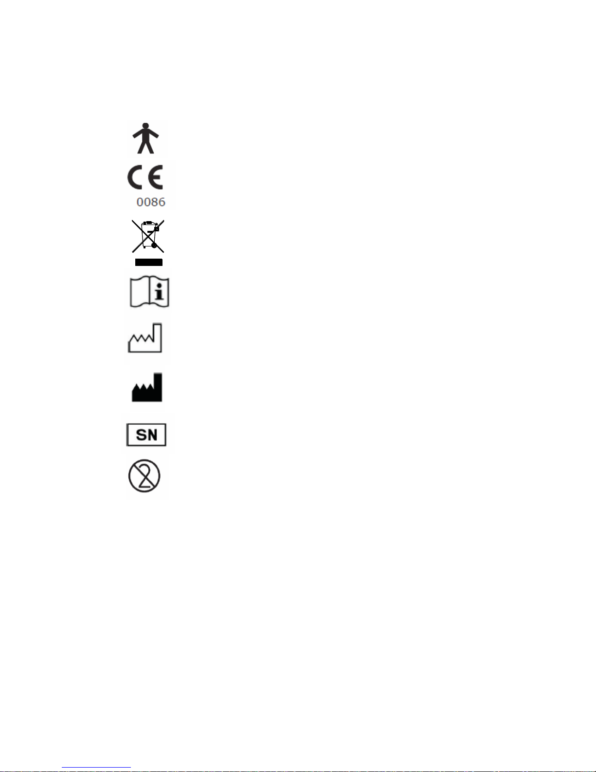
Symbols
Type B device
In accordance with Directive 93/42/EEC
Disposal in compliance with your local recycling
facility
Consult the instructions for use
Date of Manufacture
Manufacturer
Serial Number
Single Patient Use
Rx only
Federal U.S. law restricts this device to sale by or
on the order of a physician (Rx only)

23
Specifications
Measurements
Maximum Expiratory Pressure (MEP)
Maximum Inspiratory Pressure (MIP)
Sniff Nasal Inspiratory Pressure (SNIP)
With PumaTM
Maximum Rate of Pressure
Development (MRPD)
Maximum Rate of Relaxation (MRR)
Operating Pressure
+/- 300 cmH2O (+/- 5 PSID)
Burst Pressure
+/- 700 CmH2O (+/- 20 PSID)
Accuracy
+/- 3%
Resolution
1 cmH2O
Power Supply
Single Alkaline 9V battery
Dimensions
~6.5” x 2.5” x 1”
Weight (Unit with battery)
~ 6 ounces
Weight (in carry case)
~1 pound 10 ounces
Operating Temperature
32 – 104 0F
Operating Humidity
30% - 90% RH
Storage & Transport
Temperature
-4 – 158 0F
Storage & Transport
Humidity
10% - 90% RH

24
Consumables / Supporting Products
Cat. No. Description
MTH6400 Rubber mouthpiece
ASS1221 Expiration pressure valve assembly
ASS1222 Inspiration pressure valve assembly
FIL6050 Mouth pressure bacterial filters
NPROBE00 Nasal probes sizes 1 to 4
NPROBE01 Extra small nasal probes (10 per box)
NPROBE02 Small nasal probes (10 per box)
NPROBE03 Medium nasal probes (10 per box)
NPROBE04 Large nasal probes (10 per box)
ASS1091 Nasal probe adapter
48-70 Protex Disinfectant Wipe (100/canister)
To place an order for consumables/supporting products
or for general enquiries please contact Micro Direct on:
Tel: (207) 786-7808
Toll-Free: (800) 588-3381 (US and Canada only)
Fax: (207) 786-7280
Email: sales@mdspiro.com
support@mdspiro.com
Website: www.mdspiro.com
 Loading...