


MDC-i8270V(VTD) User's Manual Part1
1 MicroDigital Inc.
MDC-i8270V(VTD) User’s Manual
Part 1
(Product Overview)
MicroDigital Inc.
www.microdigital.co.kr

MDC-i8270V(VTD) User's Manual Part1
2 MicroDigital Inc.
Contents
1. Product Overview .................................................................................................................... 3
1.1. MicroDigital® ................................................................................................................... 3
1.2. MDC-i8270V(VTD) ........................................................................................................... 3
1.3. Key Functions of MDC-i8270V(VTD) ............................................................................... 4
1.4. Technical Specification of MDC-i8270V(VTD) ................................................................. 5
1.5. MDC-i8270V(VTD) Packing List ...................................................................................... 7
2. Hardware Description .............................................................................................................. 8
2.1. The front of inner part of MDC-i8270V(VTD) ................................................................... 8
2.2. The back of inner part of MDC-i8270V(VTD) ................................................................... 9
2.2.1. CTL Port Description ................................................................................................ 9
2.2.2. SPEAKER ,V-OUT JACK Description ................................................................... 10
2.2.3. MIC JACK Description ........................................................................................... 11
2.2.4. PWE Connection ................................................................................................... 11
3. MDC-i8270V(VTD) HW installation and basic setup ............................................................ 11
3.1. Before installation ......................................................................................................... 11
3.2. Factory Default Condition ............................................................................................. 12
3.3. MDC-i8270V(VTD) Hardware Installation ..................................................................... 12

MDC-i8270V(VTD) User's Manual Part1
3 MicroDigital Inc.
1. Product Overview
1.1. MicroDigital®
MicroDigital® is a device which digitizes analog Video from CCD Camera as digital stream and
transmits over Internet.
Users can monitor Video at any places in real time by MS Internet Explorer or Netscape
Communicator without any additional software, if Internet access is possible.
1.2. MDC-i8270V(VTD)
MicroDigital® MDC-i8270V(VTD) is a stand-alone device transmitting Video from built-in Analog
Camera over IP(Internet Protocol) Network.
It can transmit up to 30fps over the existing network such as LAN, leased line, DSL and Cable modem.
You can monitor Video of MDC-i8270V(VTD) through either web browser(MS IE or Netscape
Communicator), if MDC-i8270V(VTD) is connected to Network. MDC-i8270V(VTD) supports Video
compression both Motion-JPEG and H.264 simultaneously so that user can choose appropriate Video
compression for the purpose.
MDC-i8270V(VTD) supports NTSC/PAL and 3 different size and 6 levels of Video quality.
Picture 1 MDC-i8270V(VTD)

MDC-i8270V(VTD) User's Manual Part1
4 MicroDigital Inc.
1.3. Key Functions of MDC-i8270V(VTD)
Standalone device built-in web server
10M/100M Auto Sensing Ethernet
Configure and control device through Web browser
Max 30 fps transmission speed on TCP/IP network
Effective Bandwidth & Bit-rate Control (VBR/CBR) by H.264
Supports Dual Stream (Motion JPEG & H.264)
1ch Voice Encoding / 1ch Voice Decoding
Support Dynamic IP users by IPCCTVDNS server
Support Various PTZ (Pan/Ti lt/Zoom) Devices
Support Sensor Input, Digital Output
Support Transparent mode
Built-in 2 way Audio transmission (1ch A-in, 1 A-out)
Encryption functi on by user authentication
Support Modem (Dial-in, Dial-out)
Image transmission function via FTP, Email

MDC-i8270V(VTD) User's Manual Part1
5 MicroDigital Inc.
1.4. Technical Specificat ion of MDC-i8270V(VTD)
Model Name MDC-i8270V(VTD)
Hardware
32bit Embedded CPU
Flash 8Mbytes /SDRAM: 128Mbytes
Linux version 2.6.xx operating system
Battery backed up real-time clock
Image sensor
1/3” 0.7M Sony VGA Progressive CCD
Lens
2.8 ~ 11.0mm DC Auto Iris
Minimum illumination
0.5 Lux (BW, 0.1Lux)
Video related special
functions
BACKLIGHT (OFF / LOW / MIDDLE / HIGH)
AGC (OFF / LOW / MIDDLE / HIGH)
LENSE (MANUAL / DC )
SHUTTER (ESC / MANUAL / Flicker Less)
WHITE BALANCE (AT W / AWC / MANUAL)
DNR(Dynamic Noise Reduction)
Video
compression
Motion JPEG
H.264
Max Video Resolution
960 (H) X 720(V)
Max Streaming Speed
960(H) X 720(V)
25 Frame per second
640(H) X 480(H)
30 Frame per second
Video Streaming
Motion JPEG and H.264 Dual Streaming (Simultaneously)
Controllable frame rate and bandwidth
Image setting
Compression levels: 6 (Motion JPEG) / 6 (H.264)
Color: color, black & white
Voice
4 bit ADPCM, Sampling rates 8KHz, Mono Audio
1ch in & 1ch out
Bandwidth: 2KByte/sec (per channel)
Min/Max Audio Freq.: 300Hz ~ 3.4KHz
LAN interface
10/100BaseT Ethernet auto sensing
IEEE 802.3af Built-in POE
Alarm I/O Interface 1 Photo-coupled inputs and 1 Relay output
Audio Compression 8Bit PCM, 8Khz, 8KByte / Sec
Audio Support
2Way
Audio Input(MIC)
Input Impedence : 4 KOhm
Pantom Power : 5 Vol t
Gain : 20 dB
Jack : 3.5mm Mono
Audio Output(SPK)
Output Impedence : 160 Ohm
Output Power : 50 mWatt
Output Voltage : Peek To Peek 1 Volte
Jack : 3.5mm Stereo
Power Over Ethernet Option
Serial Interface
One serial port for console, modem(PSTN & GSM), serial
input/output device, PTZ
CTL Port is RS-232, RS-485
Max Baudrate: 115200 bit/s
Security features
Multi user level protection for camera access,
PTZ, Alarm I/O

MDC-i8270V(VTD) User's Manual Part1
6 MicroDigital Inc.
Advanced Service
Up to 15.5M memory for Pre/Post alarm buffer
e-mail, FTP, alarm Buffer by event or schedule
IP notification, Alarm Notification to e-mail,
CGI Call by event or schedule
Built-in Motion detections
Accuracy: 12x12=144 blocks
Motion Sensitivity : -100 ~ 100 : 100 is hypersensitive
Others
Transmit Serial input data transfer with Video
IP notification by e-mail
Management
Configurable by serial, web or telnet
Remote system update via telnet, FTP OR web browser.
PWR Supply
SMPS
input: 100~240VAC, 300mA
Output: DC 12 Volt, 800mA
PWR Consumption DC 12Volt Max 600 mA
Operating Environment
Temperature : 32° ~ 122°F (0° ~ 50°C)
Humidity : 20 ~ 80% RH(non-condensing)
Simultaneous users Live-cast for up to 16 clients
Installation, management
and maintenance
Installation CD and web-based configuration
Firmware upgrades over HTTP or FTP , firmware available at
www.microdigital.co.kr
Video access from Web
browser
Video access from Web browser
Minimum Web browsing
requirements
Pentium III CPU 500 MHz or higher
Windows XP, 2000, NT4.0*,
Internet Explorer 6.x or later
System integration support
Powerful API for software integration available at
http://www.microdigital.co.kr, including Simple Viewer API,
MicroDigital Control SDK, event trigger data in video stream,
embedded scripting and access to serial port peripherals over
HTTP/TCP
User can be installed user program daemon for event notification or
sending image.
Embedded operating system: Linux 2.4
Supported protocols
HTTP, TCP/IP, FTP, Telnet , RARP, PPP, PAP, CHAP, DH CP, SMTP
client(e- mail), NTP, RTP/RTSP
Applications
MicroDigital CMS, MicroDigital Softwate NVR(MDR-IS004)
Included Accessories
Power supply 12 V DC / Power cord
Mounting brackets
Connector kit
Installation Guide (Hard copy)
CD (Installation wizard, user's manual, quick install guide &
software),
Dimensions (HxWxD) and
weight (1lbs = 454g)
145pi * 120mm(H)
Weight: 884.5g (1.948 lbs) without power supply.
1000 kg (2200 lbs) impact-resident casing
Polycarbonate clear dome glass
Metal base
Table 1 : MDC-i8270V(VTD) Specification

MDC-i8270V(VTD) User's Manual Part1
7 MicroDigital Inc.
1.5. MDC-i8270V(VTD) Packing List
MDC-i8270V(VTD)’s packing box includes the following items
MDC-i8270V(VTD) 1ea
Power Supply Unit
(Power Cable & SMPS DC12V 0.8A Adapter)
1ea
Direct LAN Cable 1ea
CD (User’s Manual, installation wizard and Pictures) 1ea
MD-PWE Adapter (To supply power to MDC-i8270V(VTD)
through the LAN Cable.)
Optio
n
MD-POE Adapter (To supply power to MDC-i8270V(VTD)
through the LAN Cable From POE Router)
Optio
n
Table 2 : MDC-i8270V(VTD) Packing List
Please check all the listed items are included in your package. For any missing items, please contact
your local distributor.

MDC-i8270V(VTD) User's Manual Part1
8 MicroDigital Inc.
2. Hardware Description
2.1. The front of inner part of MDC-i8270V(VTD)
Picture 2 Front of inner part
A B C D E F G
Name Description
A CTL Conn. CTL Port (RS-485, RS-232, DI, DO)
B
Bolt for positioning
module (Up and
Down)
Move the position of Module up and down (Fix the position when
install)
C Camera Module Camera module to input Video
D
Bolt for positioning
module (Right and
Left)
Move the position of Module right and left (Fix the position when
install)
E Main Body Mainboard and Camera Module
F LAN LAN Connector to receive data and power from MD-PWE adapter.
E Vandal Dome Cover to protect Camera Module
Table 3 : The front of inner part of MDC-i8270V(VTD) Description

MDC-i8270V(VTD) User's Manual Part1
9 MicroDigital Inc.
2.2. The back of inner part of MDC-i8270V(VTD)
Picture 3 The back of inner part
A B C D E F
Name Description
A LAN LAN Connector to receive data and power from MD-PWE adapter.
B
SPEAKER ,V-OUT
Conn.
Speaker Port ,Video Output Port
C Cable Hole Hole for cable out
D
Bolt for positioning
module (Up and
Down)
Move the position of Camera up and down (Fix the position when
install)
E MIC Conn. MIC Port
F CTL Conn. CTL Port (RS-485, RS-232, DI, DO)
Table 4 : The back of inner part of MDC-i8270V(VTD) Description
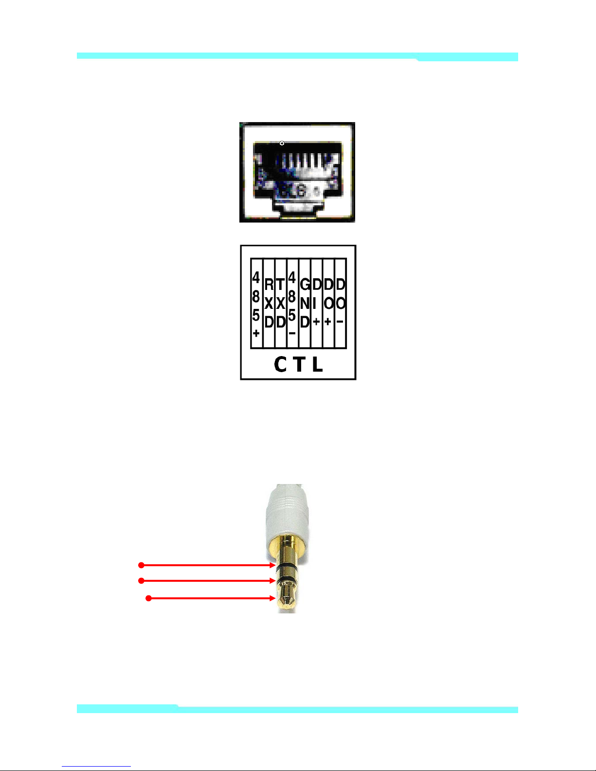
2.2.1. CTL Port Description
Pin-out information of COM port.
It’s RS-232 port for Serial input device, Modem or Console (Hyperterminal.connection). For RS-232
connection, RXD,TXD and GND are used. For connection to PC, RXD and TXD are used. RXD and TXD
MDC-i8270V(VTD) User's Manual Part1
10 MicroDigital Inc.
should be cross to communicate properly
Picture 4 : CTL Port Description
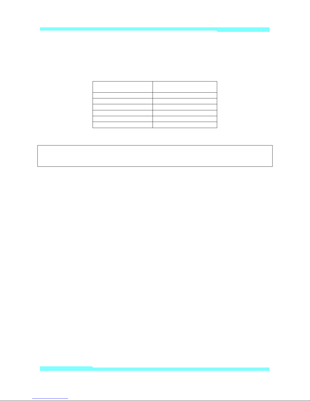
2.2.2. SPEAKER ,V-OUT JACK Description
Jack information for Mono Speaker or Video Out Jack.
1 : GND
2 : SPK
3 : V-OUT

MDC-i8270V(VTD) User's Manual Part1
11 MicroDigital Inc.
2.2.3. MIC JACK Description
Jack information for MIC
1 : GND
2 : NC
2.2.4. PWE Connection
MD-PWE adapter is to supply power to MDC-i8270V(VTD) through UTP cable without the need to
install power outlets and electrical cabli ng. Connect to UTP cable from LAN to the "HUB" port of the MDPWE adapter, and connect to adapter to MD-PWE adapter. Connect the cable from the "DEV" port of the
MD-PWE to the "LAN" port of the MDC-i8270V(VTD). After that, turn on the switch of MD-PWE adapter.
Picture 5 : MD-PWE Connection Diagram
3. MDC-i8270V(VTD) HW instal lation and basic setup
3.1. Before installation
Read carefully User's Manual.
Check User’s Network (IP Address, Network Mask and default gateway)
Secure IP address for MDC-i8270V(VTD).
MDC-i8270V(VTD) User's Manual Part1
12 MicroDigital Inc.
3.2. Factory Defaul t Condition
The following table shows the factory default condition. Please refer to this when you need to change
the values on admin menu.
Factory Default Condition
Admin ID
root
Admin password
root
IP address
10.20.30.40
Network mask
255.255.255.0
Gateway
10.20.30.1
Wireless LAN (Option)
Disabled
Table 5 : Factory Default Condition
Factory default Admin ID and Password are all lower case letters. You can change the password
with Capital letters.
3.3. MDC-i8270V(VTD) Hardware Installation
Following steps are the physical installation process for MDC-i8270V(VTD).
1. Fix the MDC-i8270V(VTD) in place
2. Connect to direct LAN from LAN to the "HUB" port of the MD-PWE adapter. Connect to
adapter to MD-PWE adapter.
3. Connect the cable from the "DEV" port of the MD-PWE to the "LAN" port of the
MDC-i8270V(VTD).
After that, you need to follow the steps below.
First, Network Configuration by MD-installer.
Second, Camera Configuration by MD-installer or admin-menu.
Third, Service Configuration by MD-instal ler or admin-menu.
You can configure most settings on Admi n menu by Web Browser so you have to configure Network
first.
 Loading...