


www.microdigital.co.kr
Full HD 1080P 2.1 Mega Pixel
CMOS HD-SDI Camera
USER MANUAL
Ver.120111E

USER INFORMATION
CAUTION
◆
• This equipment has been tested and found to comply with the limits for a Class A
CAUTION
RISK OF ELECTRIC SHOCK, DO NOT OPEN NO USER-SERVICEABLE PARTS INSIDE.
REFER FOR SERVICING TO QUALIFIED SERVICE PERSONNEL.
THIS SYMBOL INDICATES THAT DANGEROUS VOLTAGE CONSISTING OF A
RISK OF ELECTRIC SHOCK IS PRESENT WITHIN THIS UNIT.
THIS EXCLAMATION POINT SYMBOL IS INTENDED TO ALERT THE USER
TO THE PRESENCE OF IMPORTANT OPERATING AND MAINTENANCE
(SERVICING) INSTRUCTIONS IN THE LITERATURE ACCOMPANYING THE
APPLIANCE.
digital device, pursuant to part 15 of the FCC Rules. These limits are designed to
provide reasonable protection against harmful interference when the equipment
is operated in a commercial environment. This equipment generates, uses, and
can radiate radio frequency energy and, if not installed and used in accordance
with the instruction manual, may cause harmful interference to radio communica-
tions. Operation of this equipment in a residential area is likely to cause harmful
interference in which case the user will be required to correct the interference at
his own expense.
◆
• Any changes or modifications in construction of this device which are not expressly
approved by the party responsible for compliance could void the user’s authority to
operate the equipment.
• This installation should be made by a qualified service person and should abide
to all local codes.
This marking on the product, accessories or literature indicates that the product
and its electronic accessories should not be disposed of with other household
waste at the end of their working life. To prevent possible harm to the environment or human health from uncontrolled waste disposal, please separate these
items from other types of waste and recycle them responsibly to promote the
sustainable reuse of material resources. Household users should contact either
the retailer where they purchased this product, or their local government office,
for details of where and how they can take these items for environmentally safe
recycling. Business users should contact their supplier and check the terms and
conditions of the purchase contract. This product and its electronic accessories
should not be mixed with other commercial wastes for disposal.
2 MICRODIGITAL

USER INFORMATION
◆
Information
• This equipment has been tested and found to comply with the limits for a Class A
digital device, pursuant to part 15 of the FCC Rules. These limits are designed to
provide reasonable protection against harmful interference when the equipment
is operated in a commercial environment. This equipment generates, uses, and
can radiate radio frequency energy and, if not installed and used in accordance
with the instruction manual, may cause harmful interference to radio communications. Operation of this equipment in a residential area is likely to cause harmful
interference in which case the user will be required to correct the interference at
his own expense.
◆
Warning
• Any changes or modifications in construction of this device which are not expressly
approved by the party responsible for compliance could void the user’s authority to
operate the equipment.
• This installation should be made by a qualified service person and should abide
to all local codes.
MICRODIGITAL 3

USER INFORMATION
PRECAUTIONS
• Do not install the camera
in extreme temperature
conditions.
• Do not install or use the camera in an environment where
the humidity is high.
• Do not install the camera
under unstable lighting
conditions.
• Do not touch the front lens of
the camera.
• Do not drop the camera
and protect it from physical
shocks.
Only use the camera under conditions where
temperatures are between -10°C and +50°C.
Be especially careful to provide ventilation
when operating under high temperatures.
It can cause the image quality to be poor.
Severe lighting change or flicker can cause
the camera to work improperly.
This is one of the most important parts of the
camera. Be careful not to leave fingerprints
on the lens cover.
It can cause malfunctions to occur.
NOTE
• Exposure to a spotlight or an object emitting strong light may cause smear or blooming.
•
• Power supply.(Adaptor : DC12V)
- To avoid fire or shock hazard, must use a UL listed power supply.
• Monitor Impedance.
- Set the impedance switch to 75ohm standard position.
- When monitor is set to high impedance mode, the picture becomes blurred. In this
• Never keep the camera
pointed directly at strong
light.
• Do not expose the camera to
rain or spill beverage on it.
• Do not expose the camera to
radioactivity.
4 MICRODIGITAL
case, just check the position of the monitor impedance switch.
It can damage the CCD.
If it gets wet, wipe it dry immediately. Liquids
can contain minerals that corrode the
electronic components.
If exposed to radioactivity the CCD will fail.

USER INFORMATION
Ignoring this information may result
in material loss and/or serious
personal injuries including death.
Indicates “Never Allowed.”
Ignoring this information may
result in material loss and/or a
slight injuries.
Indicates “No Disassembling.”
NOTE
• Exposure to a spotlight or an object emitting strong light may cause smear or blooming.
Ensure that the power source complies with normal specifications before supplying it to
•
the camera.
• Power supply.(Adaptor : DC12V)
- To avoid fire or shock hazard, must use a UL listed power supply.
• Monitor Impedance.
- Set the impedance switch to 75ohm standard position.
- When monitor is set to high impedance mode, the picture becomes blurred. In this
case, just check the position of the monitor impedance switch.
MICRODIGITAL 5

CONTENTS
• DESCRIPTION 8 - 10
• SPECIFICATION 11 - 13
• FEATURES 14 - 15
• COMPONENTS 16 - 29
▪ BOX CAMERA
▪ BULLET CAMERA
▪ DOME CAMERA
▪ VANDAL CAMERA
16 - 18
19 - 23
24 - 26
27 - 28
• INSTALLATION 29 - 34
▪ BOX CAMERA
▪ BULLET CAMERA
▪ DOME CAMERA
▪ VANDAL CAMERA
29 - 30
31
32
33 - 34
• OSD OPERATION 35 - 42
▪ BOX CAMERA
▪ BULLET CAMERA
▪ DOME CAMERA
35
36 - 37
38
▪ VANDAL CAMERA
• INSTRUCTIONS 40
• OSD STRUCTURE 41
6 MICRODIGITAL
38

CONTENTS
• OSD STRUCTURE
-MAIN MENU
• MODEL
EXPOSURE 44
•
WHITE BALANCE 47
•
IMAGE 48
•
INTELLIGENCE
•
SPECIAL FUNC
•
DISPLAY
•
43
50
51
53
MICRODIGITAL 7

DESCRIPTION
Before operating the camera, confirm the camera model and proper input
power voltage. In order to help you understand this manual thoroughly,
we’ll introduce our model description.
◆ MODEL DESCRIPTION
• EX)
MDC - H8220 - TDN - 30 HU
Built in Heater / UTC
Number of IR-LED
H 8 2 2 0
Day / Night
CASE TYPE MODEL
1: MINI BULLET
2: MODULE
3: MINI SQUARE
4: BOX
5: ZOOM
6: IR BULLET
7: IN DOOR
DOME
8: OUT DOOR
DOME
(VANDAL)
9: MINI VANDAL
Model type
8 MICRODIGITAL
Filter mechanism
Power source
Number of Pixels
B/W(1) / Color(2)
Case type
IR & HEATER (MDC-6xxx, 7xxx, 8xxx MODEL)
-30 -30H

DESCRIPTION
CASE TYPE MODEL
TYPE
1: MINI BULLET
2: MODULE
3: MINI SQUARE
4: BOX
5: ZOOM
6: IR BULLET
7: IN DOOR
DOME
8: OUT DOOR
DOME
(VANDAL)
9: MINI VANDAL
i : IP
H : HD
COLOR PIXEL POWER D/N
LENS
1: B/W
2: COLOR
1: 270K
2: 410K
6: 1.3M
9: 2.1M
0: DC 12V
1: DUAL
VOLTAGE
(DC 12V/
AC24V)
2: AC230V
C
CTD
CDN
F
FDN
TDN
V
VX
VTD
VDN
WDN
F(E)
V(E)
IR/HEATER
/ CASE
IR : No. of
IR-LED
H: With Heater
U : UTC
CONTROL
MS : SUFACE
MOUNT TYPE
MF : FLUSH
MOUNT TYPE
IR & HEATER (MDC-6xxx, 7xxx, 8xxx MODEL)
Heater
-H -U
Built-in Heater UTC Remote Control
LED
-30 -30H
Built-in IR LED
IR
Heater
Built-in IR LED
With Heater
MICRODIGITAL 9
IR
LED

DESCRIPTION
PRECAUTIONS
Image Sensor 1/3" Panasonic CMOS
DAY / NIGHT FILTER & MECHANISM
C F
CTD
V
DAY / NIGHT
DIGITAL DAY / NIGHT DIGITAL DAY / NIGHT
DAY / NIGHT
TRUE DAY / NIGHT (ICR-IR Cut Filter Removable)
DAY / NIGHT
DC Auto
Iris Lens
DIGITAL DAY / NIGHT
FILTER CHANGE
VARIFOCALVARIFOCAL
LENS
DAY / NIGHT
Fixed
Fixed
LENS
Total Pixels 2010(H) x 1108(V) = 2,227,080 (pixel)
Active pixels 1944(H) x 1092(V) = 2,122,848 (pixel)
Scanning system Progressive
Resolution
Min. illumination
Video Output HD-SDI / Analog : NTSC, PAL(without WDR)
S/N Ratio more than 50dB (AGC off)
Function
MODE D&N / COLOR / IR SMART / IR CDS
EXPOSURE
BRIGHTNESS 0 ~ 20 steps
LENS DC / Manual
SHUTTER Auto / Manual ( 1/30(1/25) ~ 1/60000 )
DSS Off / x2 / x3 / x4
AGC Off / On
VTD
DAY / NIGHT
POWER SOURCE
DC 12V
MDC-xxx0
- DC 12V
10 MICRODIGITAL
DC Auto
Iris Lens
VARIFOCALVARIFOCAL
LENS
FILTER CHANGE
TRUE DAY / NIGHT (ICR-IR Cut Filter Removable)
AC 24V
DC 12V
MDC-xxx1
- AC 24V / DC 12V, Dual-Power
AC 230V
MDC-xxx2
- AC 230V
WDR/BLC Off / WDR / BLC
DAY&NIGHT Auto / Day / Night / Ext
SMART IR Off / On
WHITE BAL Auto / Push / Manual / Indoor / Outdoor
IMAGE
SHARPNESS 0 ~ 10 steps
MIRROR Off / H / V / H&V
FREEZE Off / On
D.ZOOM x1 ~ x32
HLC Off / On
ACE Off / On
DNR Off / Low / Middle / High / Auto
D.COMPRESS Off / On

SPECIFICATION
Image Sensor 1/3" Panasonic CMOS
Total Pixels 2010(H) x 1108(V) = 2,227,080 (pixel)
Active pixels 1944(H) x 1092(V) = 2,122,848 (pixel)
Scanning system Progressive
Resolution
Min. illumination
Video Output HD-SDI / Analog : NTSC, PAL(without WDR)
S/N Ratio more than 50dB (AGC off)
Function
MODE D&N / COLOR / IR SMART / IR CDS
EXPOSURE
BRIGHTNESS 0 ~ 20 steps
LENS DC / Manual
SHUTTER Auto / Manual ( 1/30(1/25) ~ 1/60000 )
DSS Off / x2 / x3 / x4
AGC Off / On
WDR/BLC Off / WDR / BLC
DAY&NIGHT Auto / Day / Night / Ext
SMART IR Off / On
Digital : 1920x1080p(1080p/30fps)
1280x720p(720p/60fps) Analog : 700TVL
Color : 1.0 lux , BW : 0.5lux
Color DSS : 0.002 lux , BW DSS : 0.001 lux
WHITE BAL Auto / Push / Manual / Indoor / Outdoor
IMAGE
SHARPNESS 0 ~ 10 steps
MIRROR Off / H / V / H&V
FREEZE Off / On
D.ZOOM x1 ~ x32
HLC Off / On
ACE Off / On
DNR Off / Low / Middle / High / Auto
D.COMPRESS Off / On
MICRODIGITAL 11

SPECIFICATION
INTELLIGENCE
PRIVACY Off / On (32 points)
MOTION Off / On (4 points)
SPECIAL FUNC
SHADING DET Off / On
SHADING Off / On
DEFECT DET Off / On
DEFOG Off / On
SYSTEM NTSC / PAL
HD FORMAT 1080P / 720P
PG Off / On
CVBS Off / On
ID (1 ~ 255)
BAUDRATE ( 2400 / 4800 / 9600 / 19200 / 38400 /
COMM
57600/115200 )
PROTOCOL (PELCO-P / PELCO-D / UPDATE)
DEFAULT ON / DONE
Language English
MDC-H4090C
LENS C/CS Mount Without TDN Mechanism
Power Consumption Max. 2.1W(at 12V)
MDC-H4090CTD
LENS C/CS Mount With TDN Mechanism
Power Consumption Max. 2.1W(at 12V)
MDC-H6290VTD-45
Built in TDN YES
Lens Filter Changeable Vari-Focal 6.0~50.0mm DC Auto
IR LED 12pcs Giant & 30pcs IR-LED
Power Consumption Max. 7.5W(at 12V)
MDC-H6290VTD-48
Built in TDN YES
Lens Filter Changeable Vari-Focal 3.5~16.0mm DC Auto
OSD Text 0 ~ 9, A ~ Z, a ~ z
Electrical
Power Source DC12V±10%
General
Operating Temperature -10°C ~ +50°C (Humidity : 0%RH ~ 80%RH)
Storage Temperature -20°C ~ +60°C (Humidity : 0%RH ~ 90%RH)
12 MICRODIGITAL
IR LED 48pcs Include
Power Consumption Max. 7.3W(at 12V)
MDC-H8290VTD
Built in TDN YES
Lens Filter Changeable Vari-Focal 3.5~16.0mm DC Auto
Power Consumption Max. 2.1W(at 12V)
▶Specifications are subject to change without prior notice due to improvement

SPECIFICATION
MDC-H4090C
LENS C/CS Mount Without TDN Mechanism
Power Consumption Max. 2.1W(at 12V)
MDC-H4090CTD
LENS C/CS Mount With TDN Mechanism
Power Consumption Max. 2.1W(at 12V)
MDC-H6290VTD-45
Built in TDN YES
Lens Filter Changeable Vari-Focal 6.0~50.0mm DC Auto
Iris Lens
IR LED 12pcs Giant & 30pcs IR-LED
Power Consumption Max. 7.5W(at 12V)
MDC-H6290VTD-48
Built in TDN YES
Lens Filter Changeable Vari-Focal 3.5~16.0mm DC Auto
Iris Lens
IR LED 48pcs Include
Power Consumption Max. 7.3W(at 12V)
MDC-H8290VTD
Built in TDN YES
Lens Filter Changeable Vari-Focal 3.5~16.0mm DC Auto
Iris Lens
Power Consumption Max. 2.1W(at 12V)
▶Specifications are subject to change without prior notice due to improvement
MICRODIGITAL 13
IP66
Vandal Proof
SMART
IR
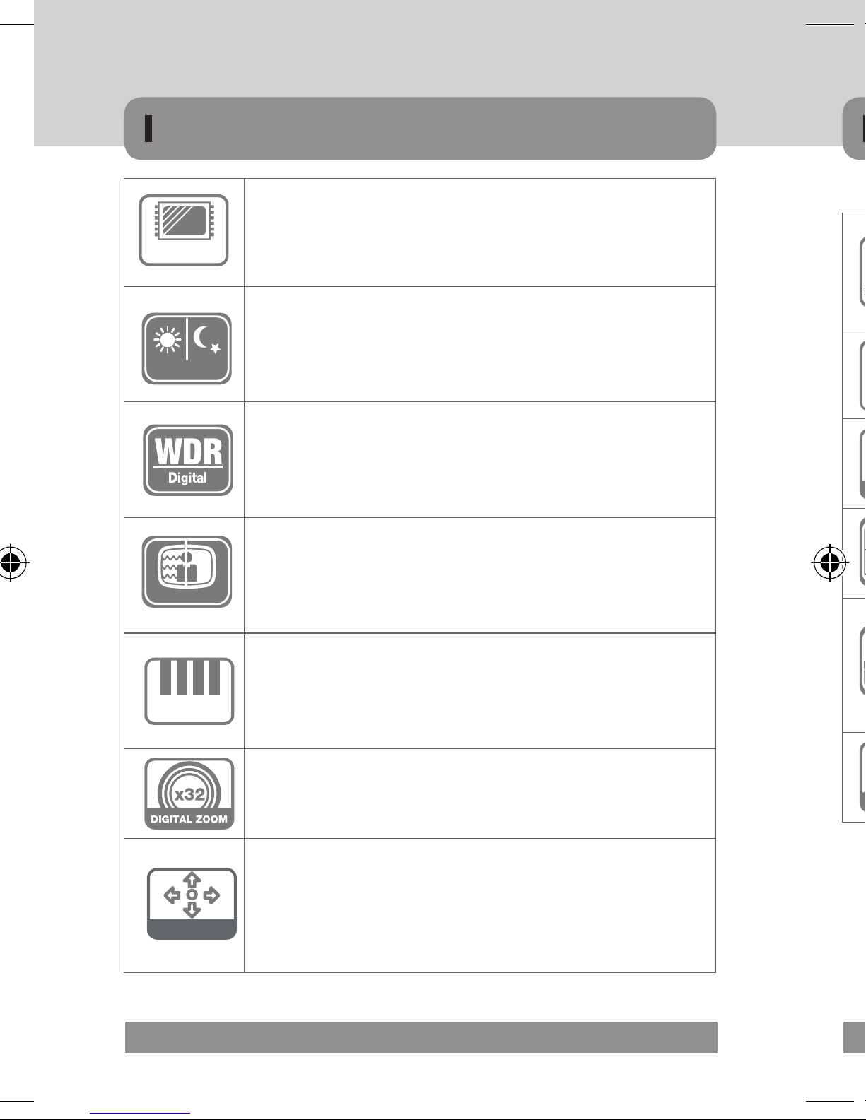
FEATURES
1/3” Progressive CMOS 2.1M pixels Image Sensor
- 2,227,080pixels(Total) / 2,122,848pixels(Active)
2.1M Full HD
DAY / NIGHT
2D+3DNR
Full HD Resolution
- 1920x1080p / 30fps - 1280x720p / 60fps
DAY / NIGHT
The camera identifies whether it is day or night and automatically switches
to the appropriate mode, depending on its environment. By day, the camera
switches to color mode in order to maintain optimal color. At night, it switches
to B/W mode so as to obtain better picture definition.
WDR (Wide Dynamic Range)
D-WDR is a powerful and ultra advanced technology that captures clear and
superior high Resolution pictures even where images appear dark because
there is a strong back light present.
DNR (Digital Noise Reduction, 2D+3D)
The DNR technology eliminates noise thus generating a distinct and clear
image. This camera DNR function utilizes both an adaptive 2D filter reducing
noise in the brightness of the image and an adaptive 3D filter reducing noise
caused by movement.
HLMASK (HLC, High Light Compensation) Function
High Spotlight BLC Function is Especially Effective to Read the Number Plate
of the Vehicles in the Street or Parking Lot at Night Time. Especially Users
HLC
Can Adjust and Select the Special Required Area to Observe the Target Object
Under the Strong Spots of Light Exist.
DIGITAL ZOOM
Digital zoom available, OFF(x1) / ON(x2~x32) can be selected
Additional Functions
1. OSD - On Screen Display menu
- the camera can be controlled by selecting text displayed on the
OSD
monitor screen.
2. Free Area Selectable function of Intelligent Motion Detection
3. Privacy Color Masking for 32 Area selection
14 MICRODIGITAL

FEATURES
DPC (Dead Pixel Compensation [Max 64points])
When the camera becomes hot after operating a couple of days, white
spots are shown on the screen especially at low light condition and they are
recorded together with normal image. By using thise function, white spots
are removed and you can get clean images.
IR SMART
SMART
IR
It enables users to distinguish the indistinguishable images saturated by
IR LED.
C / CS Mount Lens Adjustable
MDC-H4290C & CTD MODEL
External Focus & Focal Length Adjustment
77Ø, 88Ø Series (MDC-6220TDN-45, 48)
Vandal Proof
IP66
Dual(Surface / Flush) Mount Type Vandal Proof Dome Camera
MDC-H8290VTD MODEL
1. The unit is installed by two types of installation with flush or surface
mount. When the camera is installed with flush mount, the unit can be
installed into an existing two-gang junction box.
2. Surface or Flush Mounting using the supplied surface mount bracket.
Weather proof IP66
MDC-H6290VTD , MDC-H8290VTD MODEL
MICRODIGITAL 15

'&9,1
32:(5
,5,6-$&.
9,'(2287
'&
9,'(2
6(7
)*
43
1
2
w
COMPONENTS
1. Camera
2. Auto IRIS Lens Connection Plug
3. L-WRENCH
4. C - Mount Adaptor
5. Manual
H
Width Height depth
64 58 122
16 MICRODIGITAL
D
1 Lens protection cap
Cover the lens when not in use.
2 CS-mount lens adaptor
Attach the CS-mount lens here, and if you want to use C-mount lens, also please
attach C-ring to the CS-mount and then also
3 Back focus clamp screw
Loosen the clamp screw with a L-Wrench before adjusting the Back Focal length.
4 Mount bracket
Use the screw holes provided when fixing the camera onto a mounting bracket.
The mounting bracket can be attached to either the bottom or the top of the camera.

COMPONENTS
MDC-H4290C / CTD
Over view
Back focus clamp screw & Hole
3
Lens protection cap
1
CS-MOUNT Lens adaptor
2
1 Lens protection cap
Cover the lens when not in use.
2 CS-mount lens adaptor
Attach the CS-mount lens here, and if you want to use C-mount lens, also please
attach C-ring to the CS-mount and then also
3 Back focus clamp screw
Loosen the clamp screw with a L-Wrench before adjusting the Back Focal length.
4 Mount bracket
Use the screw holes provided when fixing the camera onto a mounting bracket.
The mounting bracket can be attached to either the bottom or the top of the camera.
Mount bracket
4
MICRODIGITAL 17

COMPONENTS
Rear view
1 HD-SDI Output
720p “50 / 60fps”, 1080p “30 / 25fps” resolution output, SMPTE292M
Compatible
2 CVBS Output
· D1 Resolution, “4:3” display ratio scaling (source : “16:9” display ratio)
· NTSC/PAL, This port is very helpful for installers to install HD-SDI camera easy.
3 OSD Control
Arrow – Move to Up / Down / Left / Right, MENU – Menu Setup / OK Button
4 DC IRIS JACK
5 12V / GND : DC12V Power Input
Arrow – Move to Up/Down/Left/Right, MENU – Menu Setup / OK Button
6 Power Lamp
HD-SDI
3
1
2
POWER
CVBS
DC 12V
5
DC-IRIS
HD cctv Camera
6
4
Specifications and Designs are subject to change without prior notice due to improvement
18 MICRODIGITAL

COMPONENTS
1. Varifocal IR Bullet Camera
2. Cable for Extra Video
3. L-WRENCH
4. Screw for Installation
5. Manual
MICRODIGITAL 19

COMPONENTS
MDC-H6290VTD-24H & 42 (70Ø) / 32 & 40H (90Ø)
1 Lens
2 IR-LED / Heater (Option)
3 Zoom / Focus Lever
4 OSD Joystick (Option)
5 Cable Management Bracket
6 VBS-Extra for connecting to LCD (Option)
Dimension
MDC-H6290 24H(U) 42(U) 32(U) 40H(U)
3
6
VBS-EXTRA
1
2
5
4
▶Specifications and Designs are subject to change without prior notice due to improvement
20 MICRODIGITAL

W L
COMPONENTS
Dimension
D
MDC-H6290 24H(U) 42(U) 32(U) 40H(U)
Diameter 70ø (70.91ø) 90ø (92.59ø)
Width 81.00 106.00
Length 146.05 175.5
IR LED &
Heater
24pcs IR
LED, 4pcs
Heaters
Power Consumption
Normal 140mA
IR LED ON 390mA 430mA 440mA 490mA
Heater ON 550mA X X 650mA
▶Specifications and Designs are subject to change without prior notice due to improvement
Dimension
42pcs
IR-LED
32pcs Giant
16pcs Giant /
24pcs IR-LED,
IR-LED
4pcs Heaters
MICRODIGITAL 21

HD
COMPONENTS
MDC-H6220VTD-35H & 45(77Ø) / 36H & 48 (88Ø)
1 Lens
2 IR-LED / Heater (Option)
3 Zoom / Focus Ring
4 OSD Joystick
5 Cable Management Bracket
4
6
Dimension
1
2
3
3
00
T
N
Focus / Zoom ring
fixing screw
W
6 CVBS Output
• D1 Resolution, “4:3” display ratio
scaling (source : “16:9” display ratio)
• NTSC/PAL, This port is very helpful for
installers to install HD-SDI camera easy.
7 HD-SDI Output
• 1080P “25/30fps” resolution output,
SMPTE292M Compatible
5
Focus / Zoom lever
bolt screw
IR LED & Heater
7
8
8 12V/GND : DC12V Power Input
22 MICRODIGITAL
▶Specifications and Designs are subject to change without prior notice due to improvement

W L
COMPONENTS
Dimension
D
MDC-
35H 45 36H 48
H6290VTD
Diameter 88ø (87.92ø) 77ø (76.78ø)
Width 101.03 86.90
Length 171.00 160.00
12pcs Giant
IR LED & Heater
/ 24pcs
IR-LED &
4pcs Heater
Power Consumption
Normal 170mA
IR LED ON 410mA 450mA 380mA 490mA
Dimension
12pcs Giant
& 30pcs
IR-LED
36pcs
48pcs
IR-LED &
IR-LED
4pcs Heater
Heater ON 600mA X 570mA X
▶Specifications and Designs are subject to change without prior notice due to improvement
MICRODIGITAL 23

COMPONENTS
Vandal Resistant Dome Camera
Manual
L-Wrench
(Surface Type)
Service Monitor Cable
Mounting Screw
Vandal Resistant Dome Camera
1 Lens
2 3 Axis bracket
· Adjust the pan and tilt to give the correct angle of view.
3 OSD Joystick / Board
4 VBS-Extra for connecting to LCD
· Please use the supplied wire when connecting to an external monitor.
5 IR LED
MDC-H7290VTD
(Flush Type)
Surface Mount Bracket
24 MICRODIGITAL
Manual
L-Wrench
Tapping Screw
Service Monitor Cable
Surface Mount Screw

COMPONENTS
MDC-H7290F / V, VTD, VTD-30 (100Ø)
1 Lens
2 3 Axis bracket
· Adjust the pan and tilt to give the correct angle of view.
3 OSD Joystick / Board
4 VBS-Extra for connecting to LCD
· Please use the supplied wire when connecting to an external monitor.
5 IR LED
MDC-H7290VTD
4
VBS-EXTRA
1 1
2
3
3
MDC-H7290F
1
2
3
5
2
3
MDC-H7290VTD-30
MICRODIGITAL 25

&
*
9
COMPONENTS
Dimension
1 Lens 2 OSD Joystick
3 Zoom / Focus Lever
4 3 Axis bracket
· Adjust the pan and tilt to give the correct angle of view.
5 HD-SDI Output
· 1080p ”30/25fps” resolution output, SMPTE292M Compatible
6 CVBS Output
· D1 Resolution, “4:3” display ratio scaling (source : “16:9” display ratio)
· NTSC/PAL, This port is very helpful for installers to install HD-SDI camera easy.
7 12V/GND : DC 12V Power Input
MDC-H7290 F V VTD VTD-30
Dimension
Diameter 100ø
Width 148
Height 120
IR LED
X X X
30pcs
IR-LED
Power Consumption
Normal 160mA
IR LED ON X X X 360mA
▶Specifications and Designs are subject to change without prior notice due to improvement
26 MICRODIGITAL

COMPONENTS
MDC-H8290F/ V, VTD,VTD-30,TDN-30, 30H (100Ø)
1 Lens 2 OSD Joystick
3 Zoom / Focus Lever
4 3 Axis bracket
· Adjust the pan and tilt to give the correct angle of view.
5 HD-SDI Output
· 1080p ”30/25fps” resolution output, SMPTE292M Compatible
6 CVBS Output
· D1 Resolution, “4:3” display ratio scaling (source : “16:9” display ratio)
· NTSC/PAL, This port is very helpful for installers to install HD-SDI camera easy.
7 12V/GND : DC 12V Power Input
DC 12V
+ -
3
1
7
4
5
2
6
MICRODIGITAL 27

&
*
9
COMPONENTS
Dimension
Lens
• The camera is supplied without a lens. Lenses, such as auto iris,
▹When using an auto iris lens
· Strip back about 8mm of the outer sheath of the auto iris lens cable.
· Strip off about 2mm of the insulation of wires inside the lens cable.
· Remove the cover of the auto iris lens connection plug and solder the
MDC-H8290 F V VTD VTD-30
Dimension
Diameter 100ø
Width 148mm
Height 120mm
IR LED
X X X
30pcs
IR-LED
Power Consumption
Normal 160mA
IR LED ON X X X 360mA
▶Specifications and Designs are subject to change without prior notice due to improvement
28 MICRODIGITAL

INSTALLATION
MDC-H4xxx
Lens
• The camera is supplied without a lens. Lenses, such as auto iris,
CS-Mount and C-Mount, can be used.
▹When using an auto iris lens
· Strip back about 8mm of the outer sheath of the auto iris lens cable.
· Strip off about 2mm of the insulation of wires inside the lens cable.
· Remove the cover of the auto iris lens connection plug and solder the
wires to the connector pins inside the plug, as shown below.
MICRODIGITAL 29

INSTALLATION
DC TYPE LENS
PIN NO. NAME
1 DAMP COIL -
2 DAMP COIL +
3 DRIVE COIL +
4 DRIVE COIL -
· Replace the auto iris lens connection plug cover. Remove the lens
protection cap and then attach the auto iris lens to the camera by
screwing it in clockwise.
· Insert the connection plug connected to the auto iris lens cable into
the auto lens connector jack, which is located on the rear of the
camera.
• There are three ~ four mounting holes on the bracket so that users can install the
unit in any place such as on the ceiling, On the wall, on the fence and etc.
• Fix the camera on the bracket.
• Please check the points below before connecting video & power cable.
• Adjust picture direction pan & tilt
Caution!
To avoid smear, never face the camera directly to the
strong light source such as sun or spot light.
· Set the lens selection switch, located on the rear of the camera, to ei-
ther DC or VIDEO, depending on the type of auto iris lens being used.
30 MICRODIGITAL

INSTALLATION
MDC-H6xxx
• There are three ~ four mounting holes on the bracket so that users can install the
unit in any place such as on the ceiling, On the wall, on the fence and etc.
• Fix the camera on the bracket.
• Please check the points below before connecting video & power cable.
• Adjust picture direction pan & tilt
Caution!
To avoid smear, never face the camera directly to the
strong light source such as sun or spot light.
77 / 88ø TYPE
3 AXIS BRACKET
MOUNTING SCREW
MOUNTING SCREW
70 / 90ø TYPE
CABLE MANAGEMENT BRACKET
MICRODIGITAL 31

Ceiling Ceiling
L-Wrench L-Wrench
INSTALLATION
MDC-H7xxx
• Open the dome with the ring unscrewed.
• There are two mounting holes on the dome base so that users can install the unit
in any place such as on the ceiling, on the wall, on the fence and etc.
• The mounting in any place connecting the video/power cable, before connecting
please check the below point.
• Adjust picture direction pan & tilting.
• Close the dome with the ring screwed.
BASE HOUSING
• Open the dome cover on the base by L-Wrench.
• Remove the tapping screw on the dome camera base by screw driver.
▶ Surface type
· Fixed the surface mount bracket to a ceiling using three mounting screw.
· Draw out power/video wires to the connecting places.
· Insert dome camera base into the surface mount bracket.
· Fixed the dome camera base to a surface mount
bracket using three tapping screw.
MDC-H7290VTD /
(Three Screw)
32 MICRODIGITAL
MOUNTING SCREW
DOME COVER
HOLDER
DOME COVER
MDC-H7290VTD-30
(Three Screw)

Draw out power / video wires
to the connecting places.
Fixed the camera to a celling
using four screws.
Adjust desired focus and scene
by turning and moving the
3-axis camera bracket by hand.
Put the dome cover over the
base.
Fix the dome cover on the base
by L-Wrench.
1
2
3
4
5
INSTALLATION
MDC-H8xxx
• Open the dome cover on the base by L-Wrench.
• Remove the tapping screw on the dome camera base by screw driver.
▶ Surface type
· Fixed the surface mount bracket to a ceiling using three mounting screw.
· Draw out power/video wires to the connecting places.
· Insert dome camera base into the surface mount bracket.
· Fixed the dome camera base to a surface mount
bracket using three tapping screw.
MICRODIGITAL 33

INSTALLATION
MDC-H8xxx
▶ Flush type
· Remove the surface mount bracket then insert dome camera base into
the drilled holes.
· Draw out power/video wires to the connecting places.
· Fixed the dome camera base to a ceiling using three mounting screw.
• Adjust desired focus and scene by turning and moving 3-axis by hand.
• Close the dome cover on the base by L-Wrench.
Ceiling
Fix the surface mount bracket
1
by screws on the ceiling.
Draw out power / video wires
2
to the connecting places.
Connect the dome base to the
3
surface mount bracket by screws.
1) Connection to Monitor
- As the connecting method varies with the instruments, refer to the manual sup-
plied with the instrument.
- If necessary, you can connect the monitor to the REMOTE jack on the back of
your camera.
- Only connect the cable when the power is furned off.
2) Connection to Power
- Connect the adaptor to the power input connector as shown in the following
figure. The Standard voltage for camera option : DC 12V± 10%, AC 24V ±10%.
Adjust desired focus and scene
4
by turning and moving the
3-axis camera bracket by hand.
Put the dome cover over the
5
base.
Fix the dome cover on the base
6
by L-Wrench.
34 MICRODIGITAL
Settings can be made using the 4 or 5 buttons located on the nearby of the camera.
L-Wrench

OSD OPERATION
UP
MDC-H4xxx
1) Connection to Monitor
Monitor
POWER
DC-IRIS
Camera
HD-SDI
CVBS
DC 12V
HD cctv Camera
- As the connecting method varies with the instruments, refer to the manual sup-
plied with the instrument.
- If necessary, you can connect the monitor to the REMOTE jack on the back of
your camera.
- Only connect the cable when the power is furned off.
2) Connection to Power
- Connect the adaptor to the power input connector as shown in the following
figure. The Standard voltage for camera option : DC 12V± 10%, AC 24V ±10%.
Settings can be made using the 4 or 5 buttons located on the nearby of the camera.
HD-SDI
CVBS
POWER
DC-IRIS
HD cctv Camera
DC 12V
RIGHT
LEFT
SET(Push)
DOWN
MICRODIGITAL 35

OSD OPERATION
MDC-H6xxx
1) Connection to Monitor
t
- As the connecting method varies with the instruments, refer to the manual sup-
plied with the instrument.
- If necessary, you can connect the monitor to the REMOTE jack on the back of
your camera.
- Only connect the cable when the power is furned off.
Connecting to Monitor and Power
For 12V DC Power Type
- Connect the video-out jack to the video-in jack of monitor.
- Connect the power adapter to the power input connecter.
- Use 12V DC power source.
- Use the power rated at least 600mA (12VDC)
2) Connection to Power
- Connect the adaptor to the power input connector as shown in the following figure.
The Standard voltage for camera option : DC 12V± 10%, AC 24V ±10%.
NOTE
▪ Nomal we donnot use the RS-485 addisional cable. only have power and video
36 MICRODIGITAL
MDC-H6290VTD
-35H, 36H, 45, 48
♦ Unscrew the OSD button cap

OSD OPERATION
Connecting to Monitor and Power
For 12V DC Power Type
- Connect the video-out jack to the video-in jack of monitor.
- Connect the power adapter to the power input connecter.
- Use 12V DC power source.
- Use the power rated at least 600mA (12VDC)
NO Function
#1 Video Output Yellow 1.0 Vp-p
#2 Power Input Red
Terminal
Color
Remark
12V DC(10V~15V),
Max 4.8W / 600mA
MDC-H6xxx
Video Output
GND
Push(set)
MDC-H6290VTD
-35H, 36H, 45, 48
♦ Unscrew the OSD button cap
MDC-H6290VTD
-24H, 42, 30, 40
♦ Unscrew the front cover
MICRODIGITAL 37

OSD OPERATION
MDC-H7xxx
▶CONNECTION
▪ Camera(BNC) ➜Remote Controller ➜ BNC ➜ Monitor / DVR
Push(set)
▶UTC Specification
MDC-H7290F / H7290V / H7290VTD / H7290VTD-30
(OSD JOYSTICK)
MDC-H8xxx
Without Heater type OSD Board
Support VIDEO format NTSC / PAL
Operation temperature -20°C ~ +60°C Standard
Dimension (W x D x H) 55 x 85 x 10 (mm)
• Features
▪ Long distance controller.
▪ Menu can be adjusted without opening the camera case.
▪ User can adjust OSD control during installation without the portable monitor.
▪ It is of conveniently portable size.
38 MICRODIGITAL

OSD OPERATION
UTC CONTROLLER
▶CONNECTION
▪ Camera(BNC) ➜Remote Controller ➜ BNC ➜ Monitor / DVR
Remote Controller
DVD
BNC
CON NEC TOR
▶UTC Specification
Rem ote Cont roller
Monit or / DVR
Content Spec Remark
Support VIDEO format NTSC / PAL
Video Input Level 1.0 Vp-p / 75 Ohm BNC
Video Output Level 1.0 Vp-p / 75 Ohm BNC
Control OSD, PAN/Focus
MicroDigital
Compatibility
Except Other Companies
UTC Product Family
Distance Video Output Distance TEST : 500M (RG59)
Operation temperature -20°C ~ +60°C Standard
Dimension (W x D x H) 55 x 85 x 10 (mm)
Power CR2032 X 2 Battery
• Features
▪ Long distance controller.
▪ Menu can be adjusted without opening the camera case.
▪ User can adjust OSD control during installation without the portable monitor.
▪ It is of conveniently portable size.
MICRODIGITAL 39

INSTRUCTIONS
OSD(On Screen Display) Button
▹ SET button
• Used for the menu display. This button can be used to confirm settings after
changing the value of the selected function or current conditions.
▹ UP & DOWN buttons
• Used for selecting items by moving the cursor up or down on the menu screen.
▹ LEFT & RIGHT buttons
• Used when changing item values, by moving the cursor to the left or right on the
menu screen.
Setting
▹ Use the OSD control switch on the main body of the camera
▹ Settings can be made using the 5 buttons located on the rear
of the camera
▹ Press the set switch
• The [SETUP] menu appears on the monitor screen
Menu Sub Menu Description
MODE D&N D&N / COLOR / IR SMART /IR CDS
EXPOSURE
WHITE-BAL
• Use UP and DOWN switch to select menu, then press SET switch ( )
· Submenu appears on monitor screen
• Set up selected item by using the LEFT and RIGHT switch ( )
• To finish and save the settings, select [EXIT] and press the SET button ( )
NOTE
▪ An item with the ↵ icon also has sub-menus. To select a sub-menu, press the
SET button.
▪ An item with the - - - icon has no sub-menus available for selection
40 MICRODIGITAL
IMAGE

OSD STRUCTURE
Function Menu Structure
Menu Sub Menu Description
MODE D&N D&N / COLOR / IR SMART /IR CDS
EXPOSURE
WHITE-BAL
BRIGHTNESS
Adjust brightness level - 0(dark) ~ 20(bright)
steps
LENS Select LENS type - DC / MANUAL
SHUTTER SPEED Can be set in AUTO or MANUAL 1/30(25) ~ 1/30,000
Select maximum DSS(Digital Slow Shutter)
DSS
- OFF / x2, x3, x4
AGC Select Auto Gain Control - 0 ~ 20 steps
Select WDR(Wide Dynamic Range) or
WDR / BLC
BLC(Back Light Compensation)
DAY & NIGHT Select Day & Night - AUTO / DAY / NIGHT / EXT
SMART IR OFF / ON
Select WB mode
AWB
- AUTO/PUSH/MANUAL/INDOOR/OUTDOOR
CHROMA Adjust CHROMA gain value - 0 ~ 20 steps
SHARPNESS Adjust sharpness level - 0 ~ 10 steps
MIRROR Select a flip mode - OFF / H / V / H&V
FREEZE Select real or still mode - OFF / ON
D.ZOOM
IMAGE
HLC Select High Light Compensation. - OFF / ON
ACE
DNR
D.COMPRESS Video image data compression function
Select maximum digital zoom magnification
- x1~x32
Select Digital WDR(Wide Dynamic Range)
- OFF / ON
Select Digital Noise Reduction
- AUTO/OFF/LOW/MIDDLE/HIGH
MICRODIGITAL 41

OSD STRUCTURE
Menu Sub Menu Description
Hide an area you want to hide on the screen
PRIVACY
- OFF / ON
INTELLIGENCE
MOTION
SHADING DET
SHADING
DEFECT DET
DEFOG
SPECIAL FUNC
When there is movement of the subject in
the screen, there will be an motion detection
- OFF / ON
Sets the shading calibration that the lens
will perform.
- OFF / ON
Select Lens shading compensation
- OFF / ON
Adjust sensor pixels defect compensation
- OFF / ON
Carry out defog function
- OFF / ON
Functions can be setup using Menu Key of pelco protocol.
The menu consists of the “Main Menu” and “Sub Menu”.
The main menu is displayed where 6 camera functions can be selected.
To the push of each main menu selection, the sub-menu is displayed.
DISPLAY
42 MICRODIGITAL
SYSTEM Select NTSC or PAL. (NTSC / PAL)
Select Digital output 1080P or 720P.
HD FORMAT
(1080P / 720P)
PG Select Color pattern generator - OFF/ON
CVBS Select Composite signal - OFF / ON
COMM Set up the camera ID, baud rate, protocol
All the settings will be restored to the factory
DEFAULT
default.
DISP SEL Select display item.
SET TITLE Select camera title menu (Text edit)
▶ MODE : Select mode
• D&N / COLOR / IR SMART / IR CDS

OSD STRUCTURE-MAIN MENU
MAIN MENU
MENU
MODE
EXPOSURE
WHITE BAL.
IMAGE
INTELLIGENCE
SPECIAL FUNC
DISPLAY
EXIT
D&N
Functions can be setup using Menu Key of pelco protocol.
The menu consists of the “Main Menu” and “Sub Menu”.
The main menu is displayed where 6 camera functions can be selected.
To the push of each main menu selection, the sub-menu is displayed.
MODEL
MENU
MODE
EXPOSURE
WHITE BAL.
IMAGE
INTELLIGENCE
SPECIAL FUNC
DISPLAY
EXIT
▶ MODE : Select mode
• D&N / COLOR / IR SMART / IR CDS
D&N
MICRODIGITAL 43

OSD STRUCTURE-MAIN MENU
EXPOSURE
MENU
MODE
EXPOSURE
WHITE BAL
IMAGE
INTELLIGENCE
SPECIAL FUNC
DISPLAY
EXIT
▶ BRIGHTNESS : Adjust brightness level
• 0(dark) ~ 20(bright) steps
▶ LENS : Select LENS type
• DC / MANUAL
EXPOSURE
BRIGHTNESS
LENS
SHUTTER
DSS
AGC
WDR/BLC
DAY&NIGHT
SMART IR
RETURN
| l l | l l | 10
DC
AUTO
OFF
OFF
OFF
▶WDR/BLC :
Select WDR(Wide Dynamic Range) or BLC(Back Light Compensation)
• WDR
· WEIGHT : Adjust WDR level.
» 0 ~ 3
• BLC
· AREA : Control BLC area according to light condition.
· POS-X : Adjust the window X-Axis position
· POS-Y : Adjust the window Y-Axis position
· SIZ-X : Adjust the window X-Axis size
· SIZ-Y : Adjust the window Y-Axis size
· MODE : In case of the indoor, will be recommended the INDOOR MODE
In case of the outdoor, will be recommended the OUTDOOR MODE
If Shutter rolling occurs, the MODE should be changed from OUTDOOR to INDOOR
▶ SHUTTER : Can be set in AUTO or MANUAL
• AUTO / 1/30(25),1/60(50),1/120(100),1/240,1/500,1/1000,1/2000,1/4000,
1/8000, 1/16000,1/30000,1/60000 sec
▶ DSS : Select maximum DSS(Digital Slow Shutter)
• OFF / x2, x3, x4
▶ AGC : Select Auto Gain Control
• OFF / ON
44 MICRODIGITAL
▶DAY&NIGHT : Select Day&Night
1. D&N Model
• AUTO / DAY / NIGHT / EXT
· Delay : 0 ~ 255 second
· BURST : OFF / ON
· THRS : (LOW / MIDDLE / HIGH)
According to daytime, nighttime setting the levels of transition sets to
no changes when it is dark at, higher the step it is set to
· GAP : LOW / MIDDLE / HIGH
This setting adjusts the margin of change from the setting of light to dark /
daytime to nighttime and dark to light / nighttime to daytime. If this setting
is too low then fluctuation may occur.

OSD STRUCTURE-MAIN MENU-MAIN MENU
▶WDR/BLC :
Select WDR(Wide Dynamic Range) or BLC(Back Light Compensation)
• WDR
· WEIGHT : Adjust WDR level.
» 0 ~ 3
• BLC
· AREA : Control BLC area according to light condition.
· POS-X : Adjust the window X-Axis position
· POS-Y : Adjust the window Y-Axis position
· SIZ-X : Adjust the window X-Axis size
· SIZ-Y : Adjust the window Y-Axis size
When WDR is ON, ACE and DEFOG function can not turn on.
EXPOSURE
▶DAY&NIGHT : Select Day&Night
1. D&N Model
• AUTO / DAY / NIGHT / EXT
· Delay : 0 ~ 255 second
· BURST : OFF / ON
· THRS : (LOW / MIDDLE / HIGH)
According to daytime, nighttime setting the levels of transition sets to
no changes when it is dark at, higher the step it is set to
· GAP : LOW / MIDDLE / HIGH
This setting adjusts the margin of change from the setting of light to dark /
daytime to nighttime and dark to light / nighttime to daytime. If this setting
is too low then fluctuation may occur.
MICRODIGITAL 45

OSD STRUCTURE-MAIN MENU
2. COLOR Model
• AUTO / DAY / NIGHT / EXT
· Delay : 0 ~ 255 second
· BURST : OFF / ON
· THRS : LOW / MIDDLE / HIGH
· GAP : LOW / MIDDLE / HIGH
3. IR SMART Model
• AUTO
· Delay : ---
· BURST : OFF / ON
· THRS : ---
· GAP : ---
▶ AWB : Select WHITE BALANCE mode
• AUTO / PUSH / MANUAL / INDOOR / OUTDOOR
· AUTO : Automatically adjusts color according to the available lighting.
· PUSH : It is a fixed white balance mode that may be automatically
readjusted only by pressing PUSH
4. IR CDS Model
• AUTO / DAY / NIGHT
· Delay : ---
· BURST : OFF / ON
· THRS : ---
· GAP : ---
▶DAY&NIGHT : Select Day&Night
• SMART IR : OFF / ON
· THRS : Set-up Smart IR turns on point. When you level up the value,
Smart IR turns on in a low light condition.
SMART IR function only works with IR Smart Model.
46 MICRODIGITAL
· MANUAL : Color can be corrected when the user increases or decreases
“RED GAIN” or “BLUE GAIN”.
» RED GAIN : Adjust R gain value 0 ~ 20
» BLUE GAIN : Adjust B gain value 0 ~ 20
· INDOOR : Set color temperature to be Indoor light (3700°K)
· OUTDOOR : Set color temperature to be Outdoor light (5100°K)
▶ CHROMA : Adjust CHROMA gain value
• 0 ~ 20 steps

OSD STRUCTURE-MAIN MENU
WHITE BAL
MENU
MODE
EXPOSURE
WHITE BAL
IMAGE
INTELLIGENCE
SPECIAL FUNC
DISPLAY
EXIT
AWB
CHROMA
RETURN
WHITE BAL
| l l | l l | 10
▶ AWB : Select WHITE BALANCE mode
• AUTO / PUSH / MANUAL / INDOOR / OUTDOOR
· AUTO : Automatically adjusts color according to the available lighting.
· PUSH : It is a fixed white balance mode that may be automatically
readjusted only by pressing PUSH
AUTO
· MANUAL : Color can be corrected when the user increases or decreases
“RED GAIN” or “BLUE GAIN”.
» RED GAIN : Adjust R gain value 0 ~ 20
» BLUE GAIN : Adjust B gain value 0 ~ 20
· INDOOR : Set color temperature to be Indoor light (3700°K)
· OUTDOOR : Set color temperature to be Outdoor light (5100°K)
▶ CHROMA : Adjust CHROMA gain value
• 0 ~ 20 steps
MICRODIGITAL 47

OSD STRUCTURE-MAIN MENU
IMAGE
MENU
MODE
EXPOSURE
WHITE BAL
IMAGE
INTELLIGENCE
SPECIAL FUNC
DISPLAY
EXIT
SHARPNESS
MIRROR
FREEZE
D.ZOOM
HLC
ACE
DNR
D.COMPRESS
RETURN
▶ SHARPNESS : Adjust sharpness level
• 0 ~ 10 steps
▶ MIRROR : Select a flip mode
• OFF / H / V / H&V
· H : You can flip the picture horizontally on the screen
IMAGE
OFF
OFF
X1
OFF
OFF
AUTO
OFF
▶ ACE : Select Digital WDR(Wide Dynamic Range)
• OFF / ON
5
When ACE is ON, WDR and DEFOG function can not turn on.
▶ DNR : Select Digital Noise Reduction
• AUTO / OFF / LOW / MIDDLE / HIGH
▶ D.COMPRESS : Video image data compression function.
Please use this function only IP camera.
• OFF / ON
· V : You can flip the picture vertically on the screen
· H&V : You can flip the picture horizontally & vertically on the screen
▶ Freeze : Select real or still mode
• OFF / ON
▶ D.ZOOM : Select maximum digital zoom magnification.
• x1 ~ x12, x14, x15, x18, x21, x25, x32
▶ HLC : Select High Light Compensation.
When extremely bright light is projected to the camera masking is used on the
portion to prevent partial saturation on the monitor.
• OFF / ON
· ON LEVEL : 0 ~ 20 steps
COLOR : Black, White, Yellow, Cyan, Green, Magenta, Red, Blue
48 MICRODIGITAL
▶ PRIVACY : Hide an area you want to hide on the screen
• OFF / ON
· MASK# : Select mask area number (0 ~ 31)
· MODE : Mask enable or disable (OFF / ON)
· X-POS : Adjust the mask X-Axis position
· Y-POS : Adjust the mask Y-Axis position
· X-SIZ : Adjust the mask X-Axis size
· Y-SIZ : Adjust the mask Y-Axis size
· COLOR : Cyan, Green, Magenta, Red, Blue, Black, White, Yellow
· TRANS : Select mask transparency level (0 ~ 4)

OSD STRUCTURE-MAIN MENU
IMAGE
▶ ACE : Select Digital WDR(Wide Dynamic Range)
• OFF / ON
When ACE is ON, WDR and DEFOG function can not turn on.
▶ DNR : Select Digital Noise Reduction
• AUTO / OFF / LOW / MIDDLE / HIGH
▶ D.COMPRESS : Video image data compression function.
Please use this function only IP camera.
• OFF / ON
INTELLIGENT
MENU
MODE
EXPOSURE
WHITE BAL
IMAGE
INTELLIGENCE
SPECIAL FUNC
DISPLAY
EXIT
INTELLIGENCE
PRIVACY
MOTION
RETURN
▶ PRIVACY : Hide an area you want to hide on the screen
• OFF / ON
· MASK# : Select mask area number (0 ~ 31)
· MODE : Mask enable or disable (OFF / ON)
· X-POS : Adjust the mask X-Axis position
· Y-POS : Adjust the mask Y-Axis position
OFF
OFF
· X-SIZ : Adjust the mask X-Axis size
· Y-SIZ : Adjust the mask Y-Axis size
· COLOR : Cyan, Green, Magenta, Red, Blue, Black, White, Yellow
· TRANS : Select mask transparency level (0 ~ 4)
MICRODIGITAL 49

OSD STRUCTURE-MAIN MENU
INTELLIGENT
▶ MOTION : When there is movement of the subject in the screen, there will be
an motion detection
• OFF / ON
· SENSITIVITY : Adjust sensitivity of MD (0 ~ 20 steps)
More sensitive to setting to low step with sensitivity
· AREA : Designate motion detection area (WHOLE / EACH)
· AREA# : Setting 3 areas(0~2) of motion detection
· MODE : Limit and define areas of motion detection
· X-POS : Adjust the AREA X-Axis position
· Y-POS : Adjust the AREA Y-Axis position
· X-SIZ : Adjust the AREA X-Axis size
· Y-SIZ : Adjust the AREA Y-Axis size
· TRANS : Adjust color tone of out of selected areas.
· INTERVAL :Select the alarm interval time (0 ~ 255sec)
· DWELL : Select the duration time about changing MD mode (0 ~ 255sec)
· RETURN
▶ SHADING DET :
Sets the shading calibration that the lens will perform.
Only occurs when the entire screen is viewed in white light. (OFF / ON)
▶ SHADING : Select Lens shading compensation. (OFF / ON)
▶ DEFECT DET :
Compensates for bad pixels that my occur.
Occurs when the whole screen is in full black or if there is bad pixelation and it
50 MICRODIGITAL

OSD STRUCTURE-MAIN MENU-MAIN MENU
SPECIAL FUNC
MENU
MODE
EXPOSURE
WHITE BAL
IMAGE
INTELLIGENCE
SPECIAL FUNC
DISPLAY
EXIT
SHADING DET
SHADING
DEFECT DET
DEFOG
SYSTEM
HD FORMAT
PG
CVBS
COMM
DEFAULT
RETURN
▶ SHADING DET :
Sets the shading calibration that the lens will perform.
SPECIAL FUNC
OFF
OFF
OFF
OFF
NTSC
1080P
OFF
ON
ON
Only occurs when the entire screen is viewed in white light. (OFF / ON)
▶ SHADING : Select Lens shading compensation. (OFF / ON)
▶ DEFECT DET :
Compensates for bad pixels that my occur.
Occurs when the whole screen is in full black or if there is bad pixelation and it
changes the THRS values until the screen is fixed. (OFF / ON)
MICRODIGITAL 51

OSD STRUCTURE-MAIN MENU
▶ DEFOG : Carry out defog function
• OFF / ON
· LEVEL : Eliminate amount of fog on display screen.
0 ~ 10
When DEFOG is ON, ACE and WDR function can not turn on.
▶ SYSTEM : Select NTSC or PAL. (NTSC / PAL)
▶ HD FORMAT : Select Digital output 1080P or 720P.
(1080P / 720P)
▶ DISP SEL : Select display item.
▶ PG : Select Color pattern generator. (OFF / ON)
▶ CVBS : Select Composite signal. (OFF / ON)
▶ COMM : Set up the camera ID, baud rate, protocol
• ID : Select the camera ID
· 1 ~ 255
• BAUD RATE : Select serial communication speed
· 2400 / 4800 / 9600 / 19200 / 38400 / 57600 / 115200bps
• PROTOCOL : Select operating protocol
· PELCO-D / PELCO-P / UPDATE
▶ DEFAULT : All the settings will be restored to the factory default.
• ID : OFF / ON
• TITLE : OFF / ON
• D.ZOOM : OFF / ON
▶ SET TITLE : Select camera title menu (Text edit)
52 MICRODIGITAL

OSD STRUCTURE-MAIN MENU
DISPLAY
MENU
MODE
EXPOSURE
WHITE BAL
IMAGE
INTELLIGENCE
SPECIAL FUNC
DISPLAY
EXIT
▶ DISP SEL : Select display item.
• ID : OFF / ON
• TITLE : OFF / ON
• D.ZOOM : OFF / ON
DISPLAY
DISP SEL
SET TITLE
RETURN
ON
▶ SET TITLE : Select camera title menu (Text edit)
A B C D E F G H I J K L M N O P Q R S T
U V W X Y Z a b c d e f g h i j k l m n
o p q r s t u v w x y z , . ( ) { } [ ]
0 1 2 3 4 5 6 7 8 9 * + - / = ~ ! ? " '
S P B S C L R P O S
RETURN
MICRODIGITAL 53

MEMO
54 MICRODIGITAL

MENO
MICRODIGITAL 55

www.microdigital.co.kr
Full HD 1080P 2.1 Mega Pixel
CMOS HD-SDI Camera
USER MANUAL
TOTAL SECURITYGSOLUTION
Design and specifications are subject to change without notice.
www.microdigital.co.kr
sales@microdigital.co.kr
#1212, Hoseodae Venture Tower,
319, Gasan-Dong, Geumcheon-Gu, Seoul, Korea
Ver.120111E
Tel :+82-2-2627-5279 / Fax :+82-2-2627-5295
P/N : 3690-0003A
 Loading...