

www.microdigital.co.kr
USER MANUAL
Supreme Resolution
Day & Night Color Camera
Ver.120103E

USER INFORMATION
CAUTION
◆
• This equipment has been tested and found to comply with the limits for a Class A
CAUTION
RISK OF ELECTRIC SHOCK, DO NOT OPEN NO USER-SERVICEABLE PARTS INSIDE.
REFER FOR SERVICING TO QUALIFIED SERVICE PERSONNEL.
THIS SYMBOL INDICATES THAT DANGEROUS VOLTAGE CONSISTING OF A
RISK OF ELECTRIC SHOCK IS PRESENT WITHIN THIS UNIT.
THIS EXCLAMATION POINT SYMBOL IS INTENDED TO ALERT THE USER
TO THE PRESENCE OF IMPORTANT OPERATING AND MAINTENANCE
(SERVICING) INSTRUCTIONS IN THE LITERATURE ACCOMPANYING THE
APPLIANCE.
digital device, pursuant to part 15 of the FCC Rules. These limits are designed to
provide reasonable protection against harmful interference when the equipment
is operated in a commercial environment. This equipment generates, uses, and
can radiate radio frequency energy and, if not installed and used in accordance
with the instruction manual, may cause harmful interference to radio communica-
tions. Operation of this equipment in a residential area is likely to cause harmful
interference in which case the user will be required to correct the interference at
his own expense.
◆
• Any changes or modifications in construction of this device which are not expressly
approved by the party responsible for compliance could void the user’s authority to
operate the equipment.
• This installation should be made by a qualified service person and should abide
to all local codes.
This marking on the product, accessories or literature indicates that the product
and its electronic accessories should not be disposed of with other household
waste at the end of their working life. To prevent possible harm to the environment or human health from uncontrolled waste disposal, please separate these
items from other types of waste and recycle them responsibly to promote the
sustainable reuse of material resources. Household users should contact either
the retailer where they purchased this product, or their local government office,
for details of where and how they can take these items for environmentally safe
recycling. Business users should contact their supplier and check the terms and
conditions of the purchase contract. This product and its electronic accessories
should not be mixed with other commercial wastes for disposal.
2 MICRODIGITAL

USER INFORMATION
◆
Information
• This equipment has been tested and found to comply with the limits for a Class A
digital device, pursuant to part 15 of the FCC Rules. These limits are designed to
provide reasonable protection against harmful interference when the equipment
is operated in a commercial environment. This equipment generates, uses, and
can radiate radio frequency energy and, if not installed and used in accordance
with the instruction manual, may cause harmful interference to radio communications. Operation of this equipment in a residential area is likely to cause harmful
interference in which case the user will be required to correct the interference at
his own expense.
◆
Warning
• Any changes or modifications in construction of this device which are not expressly
approved by the party responsible for compliance could void the user’s authority to
operate the equipment.
• This installation should be made by a qualified service person and should abide
to all local codes.
MICRODIGITAL 3

USER INFORMATION
PRECAUTIONS
• Do not install the camera
in extreme temperature
conditions.
• Do not install or use the camera in an environment where
the humidity is high.
• Do not install the camera
under unstable lighting
conditions.
• Do not touch the front lens of
the camera.
• Do not drop the camera
and protect it from physical
shocks.
Only use the camera under conditions where
temperatures are between -10°C and +50°C.
Be especially careful to provide ventilation
when operating under high temperatures.
It can cause the image quality to be poor.
Severe lighting change or flicker can cause
the camera to work improperly.
This is one of the most important parts of the
camera. Be careful not to leave fingerprints
on the lens cover.
It can cause malfunctions to occur.
NOTE
• Exposure to a spotlight or an object emitting strong light may cause smear or blooming.
•
the camera.
• Power supply.(Adaptor : DC12V)
- To avoid fire or shock hazard, must use a UL listed power supply.
• Monitor Impedance.
- Set the impedance switch to 75ohm standard position.
- When monitor is set to high impedance mode, the picture becomes blurred. In this
• Never keep the camera
pointed directly at strong
light.
• Do not expose the camera to
rain or spill beverage on it.
• Do not expose the camera to
radioactivity.
4 MICRODIGITAL
case, just check the position of the monitor impedance switch.
It can damage the CCD.
If it gets wet, wipe it dry immediately. Liquids
can contain minerals that corrode the
electronic components.
If exposed to radioactivity the CCD will fail.

USER INFORMATION
Ignoring this information may result
in material loss and/or serious
personal injuries including death.
Indicates “Never Allowed.”
Ignoring this information may
result in material loss and/or a
slight injuries.
Indicates “No Disassembling.”
NOTE
• Exposure to a spotlight or an object emitting strong light may cause smear or blooming.
Ensure that the power source complies with normal specifications before supplying it to
•
the camera.
• Power supply.(Adaptor : DC12V)
- To avoid fire or shock hazard, must use a UL listed power supply.
• Monitor Impedance.
- Set the impedance switch to 75ohm standard position.
- When monitor is set to high impedance mode, the picture becomes blurred. In this
case, just check the position of the monitor impedance switch.
MICRODIGITAL 5

CONTENTS
• DESCRIPTION 8 - 10
• SPECIFICATION 11 - 12
• FEATURES 13 - 14
• COMPONENTS 15 - 29
▪ BOX CAMERA
▪ BULLET CAMERA
▪ DOME CAMERA
▪ VANDAL CAMERA
15 - 17
18 - 24
25 - 27
28 - 29
• INSTALLATION 30 - 35
▪ BOX CAMERA
▪ BULLET CAMERA
▪ DOME CAMERA
▪ VANDAL CAMERA
30 - 31
32
33
34 - 35
• OSD OPERATION 36 - 42
▪ BOX CAMERA
▪ BULLET CAMERA
▪ DOME CAMERA
36 - 37
37 - 39
40
▪ VANDAL CAMERA
• INSTRUCTIONS 43
• OSD STRUCTURE 44
6 MICRODIGITAL
41

CONTENTS
• OSD STRUCTURE
-MAIN MENU
• LENS
EXPOSURE 46 - 48
•
▪ SHUTTER
▪ AGC
▪ SENS-UP
▪ BLC
▪ D-WDR
▪ RETURN
WHITE BALANCE 49 - 50
•
DAY & NIGHT
•
3D DNR
•
SPECIAL
•
51 - 52
54 - 59
45
46
46
47
47
48
48
53
▪ CAM TITLE
▪ D-EFFECT
▪ RS-485
▪ MOTION
▪ PRIVACY
▪ SYNC
▪ LANGUAGE
▪ DEFECT
ADJUST
•
RESET
•
54
55
56
56
58
59
59
59
60
61
MICRODIGITAL 7

DESCRIPTION
Before operating the camera, confirm the camera model and proper input
power voltage. In order to help you understand this manual thoroughly,
we’ll introduce our model description.
◆ MODEL DESCRIPTION
• EX)
MDC - H8220 - TDN - 30 HU
Built in Heater / UTC
Number of IR-LED
H 8 2 2 0
Day / Night
CASE TYPE MODEL
1: MINI BULLET
2: MODULE
3: MINI SQUARE
4: BOX
5: ZOOM
6: IR BULLET
7: IN DOOR
DOME
8: OUT DOOR
DOME
(VANDAL)
9: MINI VANDAL
Model type
8 MICRODIGITAL
Filter mechanism
Power source
Number of Pixels
B/W(1) / Color(2)
Case type
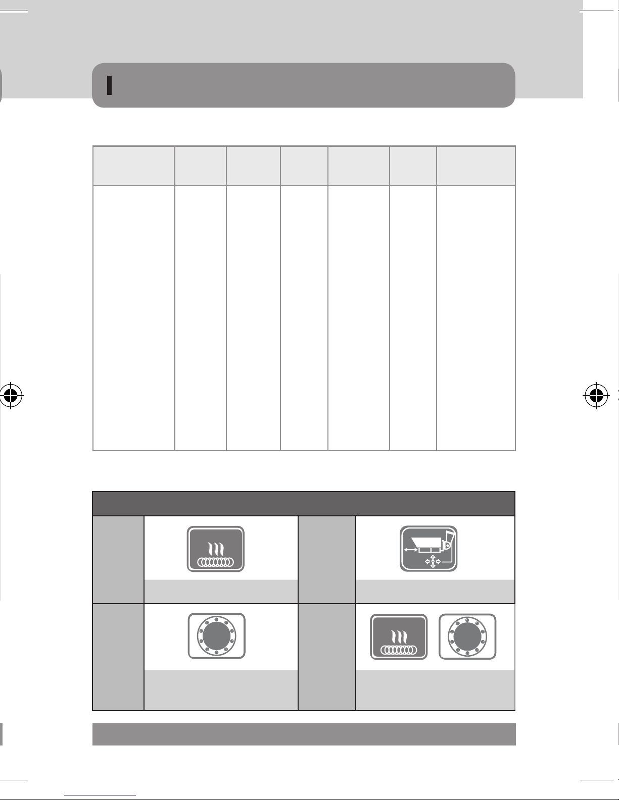
IR & HEATER (MDC-6xxx, 7xxx, 8xxx MODEL)
DESCRIPTION
CASE TYPE MODEL
TYPE
1: MINI BULLET
2: MODULE
3: MINI SQUARE
4: BOX
5: ZOOM
6: IR BULLET
7: IN DOOR
DOME
8: OUT DOOR
DOME
(VANDAL)
9: MINI VANDAL
i : IP
H : HD
COLOR PIXEL POWER D/N
LENS
1: B/W
2: COLOR
1: 270K
2: 410K
6: 1.3M
9: 2.1M
0: DC 12V
1: DUAL
VOLTAGE
(DC 12V/
AC24V)
2: AC230V
C
CTD
CDN
F
FDN
TDN
V
VX
VTD
VDN
WDN
F(E)
V(E)
IR/HEATER
/ CASE
IR : No. of
IR-LED
H: With Heater
U : UTC
CONTROL
MS : SUFACE
MOUNT TYPE
MF : FLUSH
MOUNT TYPE
IR & HEATER (MDC-6xxx, 7xxx, 8xxx MODEL)
Heater
-H -U
Built-in Heater UTC Remote Control
-30 -30H
Built-in IR LED
and CDS Sensor
IR
LED
Heater
IR
LED
Built-in IR LED
and CDS Sensor With Heater
MICRODIGITAL 9

DESCRIPTION
PRECAUTIONS
DAY / NIGHT FILTER & MECHANISM
CDN
FDN
VDN
DAY / NIGHT
DAY / NIGHT
DAY / NIGHT
Fixed
Fixed
LENS
DC Auto
Iris Lens
DIGITAL DAY / NIGHT
DIGITAL DAY / NIGHT
DIGITAL DAY / NIGHT
VARIFOCALVARIFOCAL
LENS
Signal System
Scanning Frequency 15,734KHz(H), 59.94Hz(V) 15,625KHz(H), 50.00Hz(V)
Image Sensor 1/3” Interline Transfer Type High Sensitivity Color CCD
Sync. System INT / LL
Total Pixels Number 811(H) X 508(V), 410K pixels 795(H) X 596(V), 470K pixels
Effective Pixels Number 768(H) x 494(V), 380K pixels 752(H) x 582(V), 440K pixels
Horizontal Resolution Color 600 TV Lines / BW 700 TV Lines
Video Output Level 1.0Vp-p, 75ohm (Video 0. 714Vp-p Sync. 0.286Vp-p)
S/N Ratio 52 dB (AGC OFF, Weight On)
Dynamic Range 52dB(*128)
DAY / NIGHT COLOR / AUTO / BW / EXTERNAL
Sens Up AUTO / OFF
3 DNR ON / OFF (1~100 Level Selectable)
D-WDR INDOOR / OUTDOOR / OFF
AGC OFF / LOW / MIDDLE / HIGH
BLC BLC / HSBLC
TDN
DAY / NIGHT
POWER SOURCE
DC 12V
MDC-xxx0
- DC 12V
10 MICRODIGITAL
DC Auto
Iris Lens
VARIFOCALVARIFOCAL
LENS
FILTER CHANGE
TRUE DAY / NIGHT (ICR-IR Cut Filter Removable)
AC 24V
DC 12V
MDC-xxx1
- AC 24V / DC 12V, Dual-Power
AC 230V
MDC-xxx2
- AC 230V
AWB ATW / AWB / INDOOR / OUTDOOR / MANUAL / AWC
Mirror OFF / MIRROR / V-FLIP / ROTATE
Privacy Function ON / OFF (8 Zone)
Motion Detection ON / OFF (4 Zone Selectable)
Freeze ON / OFF
Sharpness 0~31 (Level Selectable)
Digital Zoom On(*32) / OFF
MONITOR LCD / CRT / USER
DEFECT SENSE-UP / DIFFERENCE / START
Electronic Shutter 1/60sec ~ 1/100,000sec 1/50sec ~ 1/100,000sec
OSD Built-in
Operating Temperature (-)30°C ~ (+)50°C, (-)40°C ~ (+)50°C (Built-In Heater Model)
Operating Humidity 95% RH max
Power Voltage DC12V ± 10%

SPECIFICATION
Signal System
Scanning Frequency 15,734KHz(H), 59.94Hz(V) 15,625KHz(H), 50.00Hz(V)
Image Sensor 1/3” Interline Transfer Type High Sensitivity Color CCD
Sync. System INT / LL
Total Pixels Number 811(H) X 508(V), 410K pixels 795(H) X 596(V), 470K pixels
Effective Pixels Number 768(H) x 494(V), 380K pixels 752(H) x 582(V), 440K pixels
Horizontal Resolution Color 600 TV Lines / BW 700 TV Lines
Video Output Level 1.0Vp-p, 75ohm (Video 0. 714Vp-p Sync. 0.286Vp-p)
S/N Ratio 52 dB (AGC OFF, Weight On)
Dynamic Range 52dB(*128)
DAY / NIGHT COLOR / AUTO / BW / EXTERNAL
Sens Up AUTO / OFF
3 DNR ON / OFF (1~100 Level Selectable)
D-WDR INDOOR / OUTDOOR / OFF
AGC OFF / LOW / MIDDLE / HIGH
BLC BLC / HSBLC
NTSC PAL
AWB ATW / AWB / INDOOR / OUTDOOR / MANUAL / AWC
Mirror OFF / MIRROR / V-FLIP / ROTATE
Privacy Function ON / OFF (8 Zone)
Motion Detection ON / OFF (4 Zone Selectable)
Freeze ON / OFF
Sharpness 0~31 (Level Selectable)
Digital Zoom On(*32) / OFF
MONITOR LCD / CRT / USER
DEFECT SENSE-UP / DIFFERENCE / START
Electronic Shutter 1/60sec ~ 1/100,000sec 1/50sec ~ 1/100,000sec
OSD Built-in
Operating Temperature (-)30°C ~ (+)50°C, (-)40°C ~ (+)50°C (Built-In Heater Model)
Operating Humidity 95% RH max
Power Voltage DC12V ± 10%
MICRODIGITAL 11

600 TV LINE
DAY / NIGHT
3DNR
1/3” IT
CCD
HLC
SPECIFICATION
LENS
MODEL
TYPE LENS
CDN C / CS MOUNT
MDC-4xxx
TDN C / CS MOUNT (ICR-IR Cut Filter Removable Mechanism)
35H, 45, 40H, 32 Filter Changeable Vari-Focal 6.0~50.0mm DC Auto Iris Lens
MDC-6xxx
20, 20H, 36H, 48
24H, 42
TDN
32U, 40HU Filter Changeable Vari-Focal 6.0~50.0mm 2 Motor Drive Lens
24HU, 42U Filter Changeable Vari-Focal 2.8~12.0mm 2 Motor Drive Lens
FDN Built-In Fixed 3.6mm Board Lens
MDC-7xxx
VDN Vari-Focal 3.5~16.0mm DC Auto Iris Lens
TDN Filter Changeable Vari-Focal 3.5~16.0mm DC Auto Iris Lens
VDN Vari-Focal 3.5~16.0mm DC Auto Iris Lens
MDC-8xxx
TDN Filter Changeable Vari-Focal 3.5~16.0mm DC Auto Iris Lens
Min. ILLUMINATION
Filter Changeable Vari-Focal 3.5~16.0mm DC Auto Iris Lens
MODEL
MDC-4xxx
MDC-6xxx
TDN
MDC-7xxx
MDC-8xxx
▶Specifications are subject to change without prior notice due to improvement
TYPE Min. ILLUMINATION
CDN 0.15 (Color) / 0.03 (BW) / 0.00001 / Lux(Sens-up x 256)
TDN
0.25 (Color) / 0.01 (BW) / 0.00001 Lux / Lux at F1.2 (Sens-up x 256)
0 Lux at IR LEDs On (ICR-IR Cut Filter Removable Mechanism)
FDN 0.25 (Color) / 0.06 (BW) / 0.00001 / Lux at F1.2 (Sens-up x 256)
VDN 0.15 (Color) / 0.03 (BW) / 0.00001 / Lux at F1.2 (Sens-up x 256)
TDN
VDN 0.15 (Color) / 0.03 (BW) / 0.00001 / Lux at F1.2(Sens-up x 256)
TDN
0.15 (Color) / 0.01 (BW) / 0.00001 / Lux(Sens-up x 256)
(ICR-IR Cut Filter Removable Mechanism)
0.25 (Color) / 0.01 (BW) / 0.00001 / Lux at F1.2 (Sens-up x
256) (ICR-IR Cut Filter Removable Mechanism)
0.25 (Color) / 0.01 (BW) / 0.00001 / Lux at F1.2(Sens-up x 256)
(ICR-IR Cut Filter Removable Mechanism)
12 MICRODIGITAL

FEATURES
1/3” Interline Transfer Type High Sensitivity Color CCD
1/3” IT
600 TV LINE
HLC
CCD
600TV Lines
The combination of a 1/3” Interline Transfer Type High Sensitivity Color CCD
and DNR DSP provides an excellent resolution of 600 TV lines.
Min. Illumination
With an incredibly Minimum Illuminatio of Amazing 0.0001Lux can Capture
Good Images Even in Extremely Low Light Conditions and Related Noises
are Significantly Reduced by the Ultra Advanced DNR(Digital Noise Reduction) Technology.
D-WDR (Digital Wide Dynamic Range)
D-WDR is a powerful and ultra advanced technology that captures clear and
superior high Resolution pictures even where images appear dark because
there is a strong back light present.
High Light Compensation (HLC) Function
High Light Compensation Function is Especially Effective to Read the Number
Plate of the Vehicles in the Street or Parking Lot at Night Time. Especially
Users Can Adjust and Select the Special Required Area to Observe the Target
Object Under the Strong Spots of Light Exist.
3DNR
DAY / NIGHT
3D Filtering Method of Newly Advanced DNR Functionn
Newly developed 3D filtering enhances Digital Noise reduction at low light
levels. 3D Filtering of the Video Signal Optimized the Signal to Noise ratio,
giving vastly improved low light visibility and a powerful Sens-Up function
(up to 258 times magnification).
DAY / NIGHT
The camera identifies whether it is day or night and automatically switches
to the appropriate mode, depending on its environment. By day, the camera
switches to color mode in order to maintain optimal color. At night, it switches
to B/W mode so as to obtain better picture definition.
DPC (Dead Pixel Compensation [Max 64points])
When the camera becomes hot after operating a couple of days, white
spots are shown on the screen especially at low light condition and they are
recorded together with normal image. By using thise function, white spots
are removed and you can get clean images.
MICRODIGITAL 13

FEATURES
DIGITAL ZOOM
Digital zoom available, OFF(x1) / ON(x2~x32) can be selected
IR SMART
SMART
IR
OSD
It enables users to distinguish the indistinguishable images saturated by
IR LED.
Additional Functions
1. OSD - ON Screen Display menu with multi-Language support.
2. FreeArea Selectable function of BLC and MOTION DETECTION
3. Privacy Color Masking for 8 Area selection
4. Max 70% of Disk Saving Effect with Super DNR
5. Negative image Function
Weather proof IP66
MDC-6xxx , MDC-8xxx MODEL
IP66
Vandal Proof
External Focus & Focal Length Adjustment
77Ø, 88Ø Series (MDC-6220VTD-35H, 36H, 45, 48)
Dual(Surface / Flush) Mount Type Vandal Proof Dome Camera
MDC-8xxx MODEL
1. The unit is installed by two types of installation with flush or surface
mount. When the camera is installed with flush mount, the unit can be
installed into an existing two-gang junction box.
2. Surface or Flush Mounting using the supplied surface mount bracket.
C / CS Mount Lens Adjustable
MDC-4xxx MODEL
UTC Remote Controller
- Long distance controller.
- Menu can be adjusted without opening the camera case.
- It is of conveniently portable size.
14 MICRODIGITAL

COMPONENTS
'&9,1
32:(5
,5,6-$&.
9,'(2287
'&
9,'(2
6(7
)*
43
1
2
w
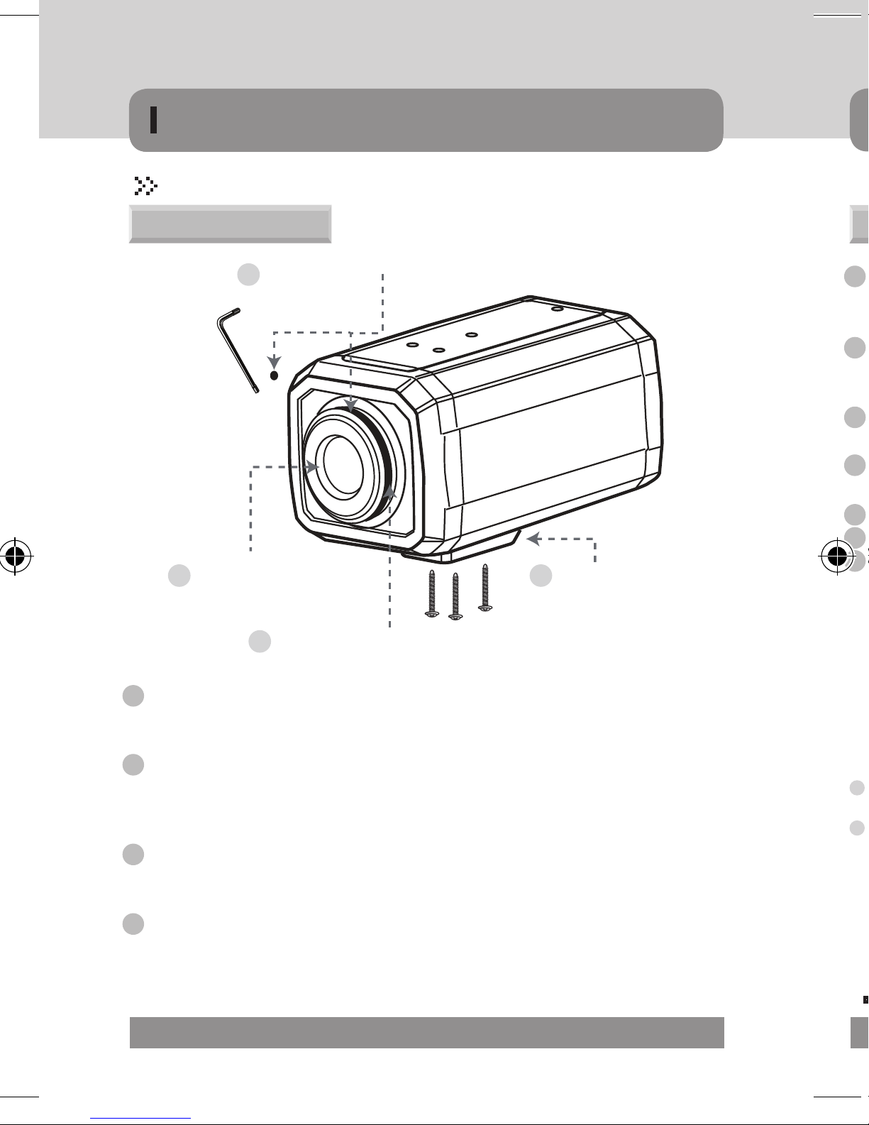
1. Camera
2. Auto IRIS Lens Connection Plug
3. L-WRENCH
4. C - Mount Adaptor
5. Manual
H
Width Height depth
64 58 102
D
MICRODIGITAL 15
DC 12V IN
AC 24V IN
POWER
IRIS JACK
VIDEO OUT
DC
VIDEO
SET
F.G
43
1
2
AC24V / DC12V
POWER
IRIS JACK
VIDEO OUT
DC
VIDEO
SET
F.G
43
1
2
AC230V
1
5
2 3 1
4
7
5
2 3
COMPONENTS
MDC-4220CDN / TDN
Over view
Back focus clamp screw & Hole
3
Lens protection cap
1
Mount bracket
4
1 Auto iris lens connector
Connection terminal for an auto iris lens.
2 Auto iris lens selection switch
Used to change between DC or Video depending upon the type of auto iris in use.
3 Video output terminal
Sends video signals and connects to the video input terminal of the monitor.
4 Power lamp
Lights up when the correct power is supplied to the camera.
5 OSD button
6 Power input terminal : Low voltage power connection.
7 AC Power Cord : Accept AC90~240V-50Hz/60Hz
CS-MOUNT Lens adaptor
2
1 Lens protection cap
Cover the lens when not in use.
2 CS-mount lens adaptor
Attach the CS-mount lens here, and if you want to use C-mount lens, also please
attach C-ring to the CS-mount and then also
3 Back focus clamp screw
Loosen the clamp screw with a L-Wrench before adjusting the Back Focal length.
4 Mount bracket
Use the screw holes provided when fixing the camera onto a mounting bracket.
The mounting bracket can be attached to either the bottom or the top of the camera.
16 MICRODIGITAL
MDC-4xx0/ 4xx1
4
6

COMPONENTS
Rear view
1 Auto iris lens connector
Connection terminal for an auto iris lens.
2 Auto iris lens selection switch
Used to change between DC or Video depending upon the type of auto iris in use.
3 Video output terminal
Sends video signals and connects to the video input terminal of the monitor.
4 Power lamp
Lights up when the correct power is supplied to the camera.
5 OSD button
6 Power input terminal : Low voltage power connection.
7 AC Power Cord : Accept AC90~240V-50Hz/60Hz
MDC-4xx0/ 4xx1
1
IRIS JACK
1
4
POWER
AC 24V IN
6
DC 12V IN
AC24V / DC12V
2 3 1
DC
VIDEO
VIDEO OUT
F.G
2
43
5
SET
MDC-4xx2
IRIS JACK
2
1
43
4
7
POWER
2 3
VIDEO OUT
DC
VIDEO
F.G
AC230V
Specifications and Designs are subject to change without prior notice due to improvement
MICRODIGITAL 17
5
SET

VBS-EXTRA
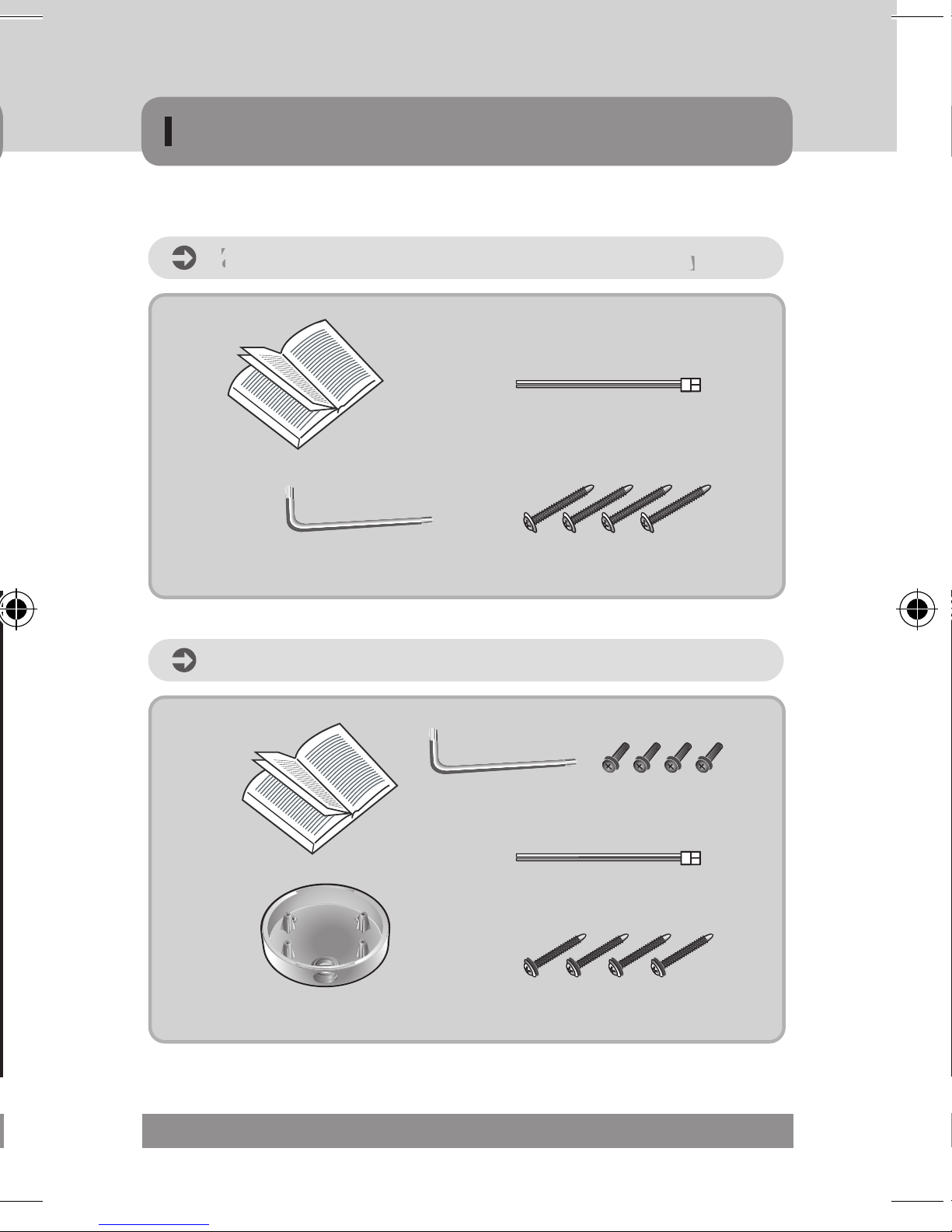
COMPONENTS
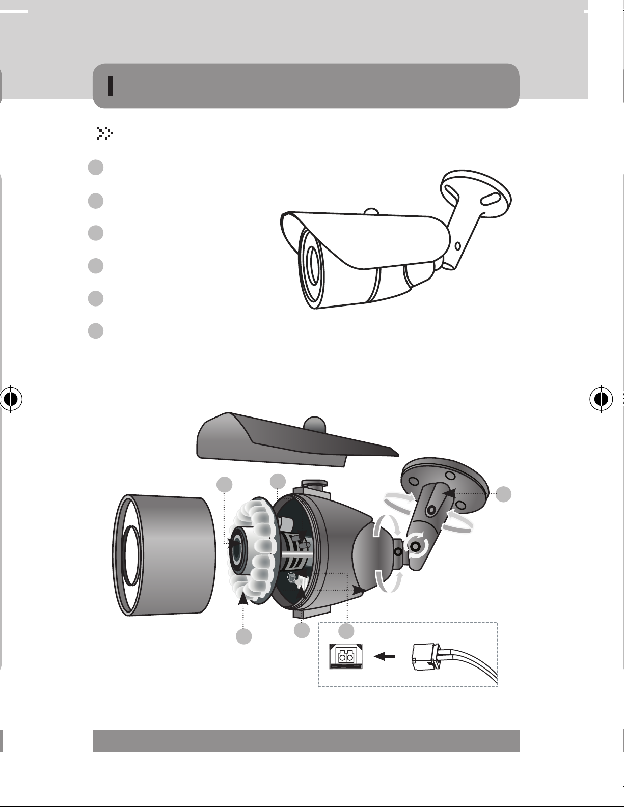
1 Lens
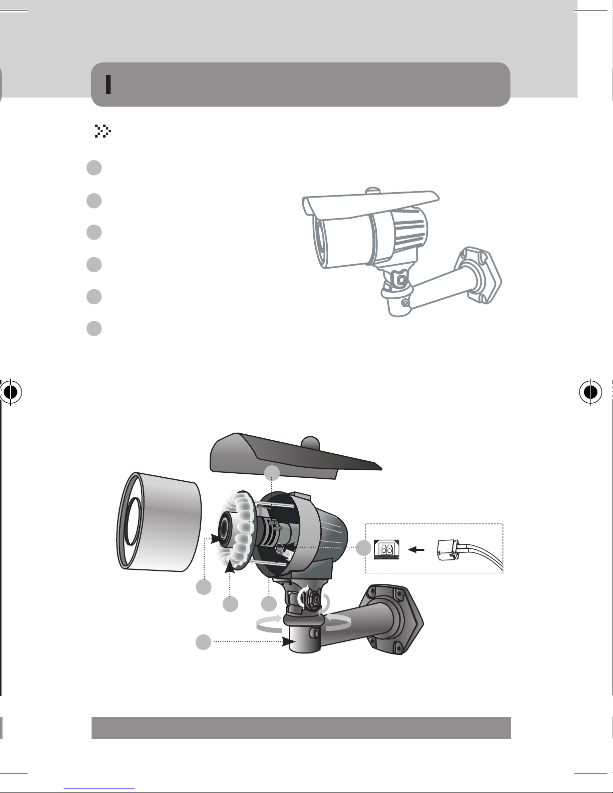
1. Varifocal IR Bullet Camera
2. Cable for Extra Video
3. L-WRENCH
2 IR-LED / Heater (Option)
3 Zoom / Focus Lever
4 OSD Joystick (Option)
5 Cable Management Bracket
6 VBS-Extra for connecting to LCD (Option)
4. Screw for Installation
5. Manual
18 MICRODIGITAL
COMPONENTS
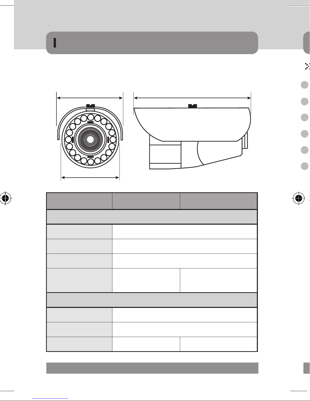
MDC-6220TDN-20 & 20H (65Ø)
1 Lens
2 IR-LED / Heater (Option)
3 Zoom / Focus Lever
4 OSD Joystick (Option)
5 Cable Management Bracket
6 VBS-Extra for connecting to LCD (Option)
1
2
3
5
4
6
VBS-EXTRA
MICRODIGITAL 19
L
W
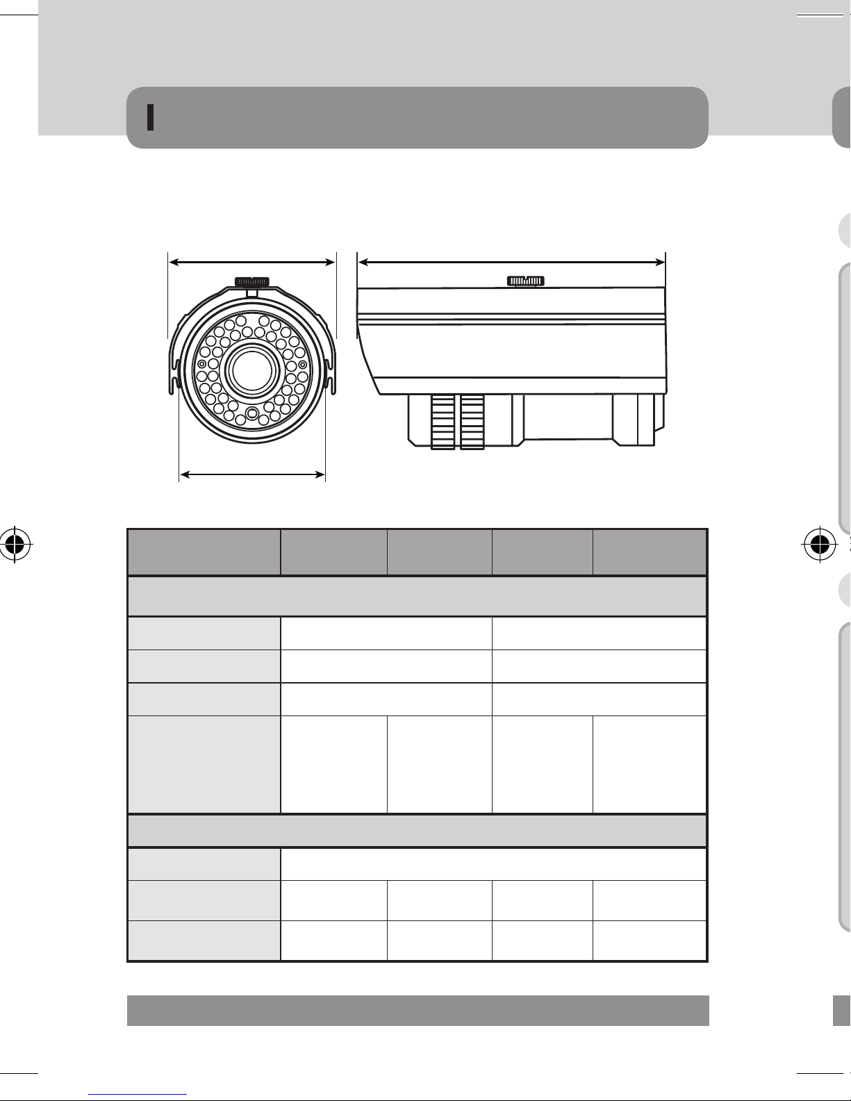
COMPONENTS
Dimension
D
1 Lens
2 IR-LED / Heater (Option)
3 Zoom / Focus Lever
4 OSD Joystick (Option)
5 Cable Management Bracket
6 VBS-Extra for connecting to LCD (Option)
MDC-6220 20 20H
Dimension
Diameter 65ø (63.09ø)
Width 74.00
Length 146.80
IR LED & Heater 20pcs IR LED
Power Consumption
Normal 140mA
IR LED ON 320mA
Heater ON X 460mA
20pcs IR-LED,
3pcs Heater
▶Specifications and Designs are subject to change without prior notice due to improvement
20 MICRODIGITAL
COMPONENTS
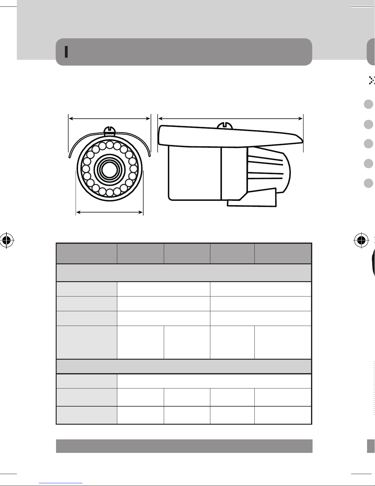
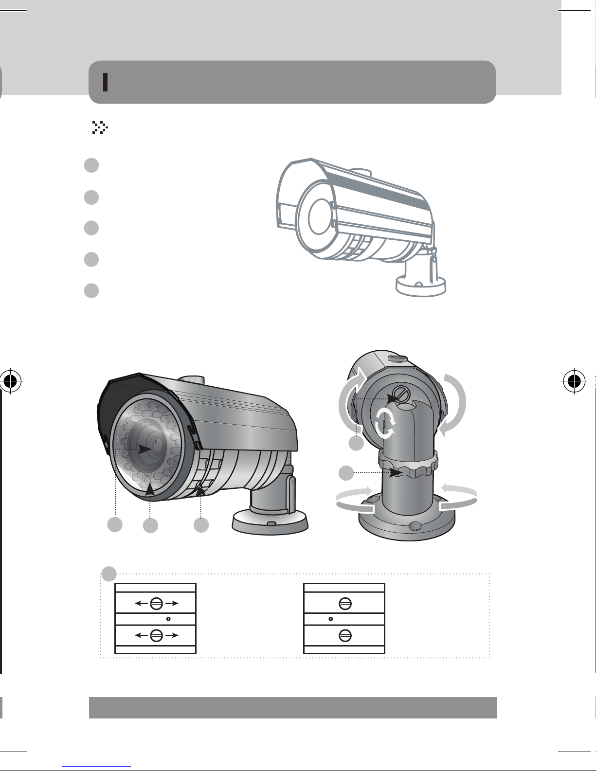
MDC-6220TDN-24H & 42 (70Ø) / 32 & 40H (90Ø)
1 Lens
2 IR-LED / Heater (Option)
3 Zoom / Focus Lever
4 OSD Joystick (Option)
5 Cable Management Bracket
6 VBS-Extra for connecting to LCD (Option)
3
6
VBS-EXTRA
1
2
5
4
MICRODIGITAL 21
W L
HD
COMPONENTS
Dimension
1 Lens
2 IR-LED / Heater (Option)
3 Zoom / Focus Ring
4 OSD Joystick
5 Cable Management Bracket
D
MDC-6220 24H(U) 42(U) 32(U) 40H(U)
Dimension
Diameter 70ø (70.91ø) 90ø (92.59ø)
Width 81.00 106.00
Length 146.05 175.5
IR LED &
LED, 4pcs
Heater
Normal 140mA
IR LED ON 350mA 500mA 570mA 440mA
Heater ON 480mA X X 570mA
▶Specifications and Designs are subject to change without prior notice due to improvement
22 MICRODIGITAL
20pcs IR
42pcs
IR-LED
Heaters
Power Consumption
32pcs Giant
16pcs Giant /
24pcs IR-LED,
IR-LED
4pcs Heaters
HD
COMPONENTS
MDC-6220TDN-35H & 45(77Ø) / 36H & 48 (88Ø)
1 Lens
2 IR-LED / Heater (Option)
3 Zoom / Focus Ring
4 OSD Joystick
5 Cable Management Bracket
4
5
1
3
2
00
T
3
Focus / Zoom ring
N
fixing screw
W
Focus / Zoom lever
bolt screw
MICRODIGITAL 23
W L
Surface Mount Bracket
Tapping Screw
Surface Mount Screw
Service Monitor Cable
Service Monitor Cable
L-Wrench
L-Wrench
andal Resistant Dome Camera
(Surface T
ype)
Vandal Resistant Dome Camera
(Surface Type)
Vandal Resistant Dome Camera
(Flush Type)
Manual
Manual
Mounting Screw
COMPONENTS
Dimension
D
MDC-6220VTD 35H 45 36H 48
Dimension
Diameter 88ø (87.92ø) 77ø (76.78ø)
Width 101.03 86.90
Length 171.00 160.00
12pcs Giant
IR LED & Heater
/ 23pcs
IR-LED &
4pcs Heater
12pcs Giant
& 33pcs
IR-LED
36pcs
48pcs
IR-LED &
IR-LED
3pcs Heater
Power Consumption
Normal 140mA
IR LED ON 520mA 620mA 480mA 580mA
Heater ON 660mA X 660mA X
▶Specifications and Designs are subject to change without prior notice due to improvement
24 MICRODIGITAL
andal Resistant Dome Camera
(Surface T
ype)
COMPONENTS
Vandal Resistant Dome Camera
Manual
L-Wrench
Service Monitor Cable
Mounting Screw
(Surface Type)
Vandal Resistant Dome Camera
(Flush Type)
Manual
Surface Mount Bracket
L-Wrench
Tapping Screw
Service Monitor Cable
Surface Mount Screw
MICRODIGITAL 25

COMPONENTS
MDC-7220FDN (68Ø) / 7220VDN, TDN, TDN-30 (100Ø)
1 Lens
2 3 Axis bracket
· Adjust the pan and tilt to give the correct angle of view.
3 OSD Joystick / Board
4 VBS-Extra for connecting to LCD
· Please use the supplied wire when connecting to an external monitor.
5 IR LED
MDC-7220FDN
3
4
VBS-EXTRA
1 1
2
MDC-7220TDN-30
3
MDC-7220VDN / TDN
3
2
1
5
26 MICRODIGITAL
2
▶Specifications and Designs are subject to change without prior notice due to improvement

MDC-7220V / VTD (100Φ)
MDC-7220V TD-30 (100Φ)
MDC-7220F (68Φ)
D
D
H
H
H
W
W
W
D
COMPONENTS
Dimension
MDC-7220 FDN VDN TDN VTD-30
Diameter 68ø 100ø
Width 90 130 135
Height 62 92 100
IR LED
Normal 150mA 170mA
IR LED ON X X X 450mA
▶Specifications and Designs are subject to change without prior notice due to improvement
Dimension
X X X
Power Consumption
30pcs
IR-LED
MICRODIGITAL 27

COMPONENTS
MDC-8220VDN / TDN-30, 30H (100Ø)
1 Lens
2 IR-LED
3 OSD Board / Heater (Option : 6pcs)
4 Zoom / Focus Lever
5 VBS-Extra for connecting to LCD
· Please use the supplied wire when connecting to an external monitor.
6 3 Axis bracket
· Adjust the pan and tilt to give the correct angle of view.
2
1
4
3
28 MICRODIGITAL
6
5
VBS-EXTRA
▶Specifications and Designs are subject to change without prior notice due to improvement

&
*
9
COMPONENTS
Dimension
MDC-8220 VDN TDN TDN-30 TDN-30H
Dimension
Diameter 100ø
Height 108mm
Width 151mm
30pcs
IR-LED, 6pcs
Heater
IR LED
X X
30pcs
IR-LED
Power Consumption
Normal 200mA
IR LED ON X X 400mA 400mA
Heater ON X X X 460mA
▶Specifications and Designs are subject to change without prior notice due to improvement
MICRODIGITAL 29

INSTALLATION
MDC-4xxx
Lens
• The camera is supplied without a lens. Lenses, such as auto iris,
CS-Mount and C-Mount, can be used.
▹When using an auto iris lens
PIN NO. NAME WIRE COLOR NAME WIRE COLOR
1 OPEN NOT USE DAMP COIL - GREEN
· Strip back about 8mm of the outer sheath of the auto iris lens cable.
· Strip off about 2mm of the insulation of wires inside the lens cable.
· Remove the cover of the auto iris lens connection plug and solder the
wires to the connector pins inside the plug, as shown below.
2 VIDEO WHITE DAMP COIL + RED
3 POWER RED DRIVE COIL + BLACK
4 GROUND BLACK DRIVE COIL - BROWN
· Replace the auto iris lens connection plug cover. Remove the lens
· Insert the connection plug connected to the auto iris lens cable into
· Set the lens selection switch, located on the rear of the camera, to ei-
30 MICRODIGITAL

INSTALLATION
VIDEO TYPE LENS DC TYPE LENS
PIN NO. NAME WIRE COLOR NAME WIRE COLOR
1 OPEN NOT USE DAMP COIL - GREEN
2 VIDEO WHITE DAMP COIL + RED
3 POWER RED DRIVE COIL + BLACK
4 GROUND BLACK DRIVE COIL - BROWN
· Replace the auto iris lens connection plug cover. Remove the lens
protection cap and then attach the auto iris lens to the camera by
screwing it in clockwise.
· Insert the connection plug connected to the auto iris lens cable into
the auto lens connector jack, which is located on the rear of the
camera.
· Set the lens selection switch, located on the rear of the camera, to ei-
ther DC or VIDEO, depending on the type of auto iris lens being used.
MICRODIGITAL 31
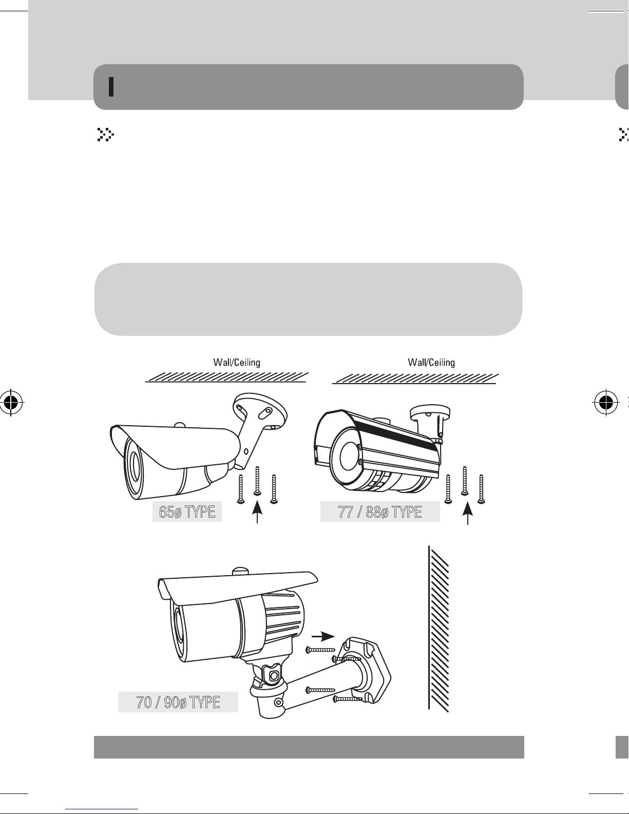
INSTALLATION
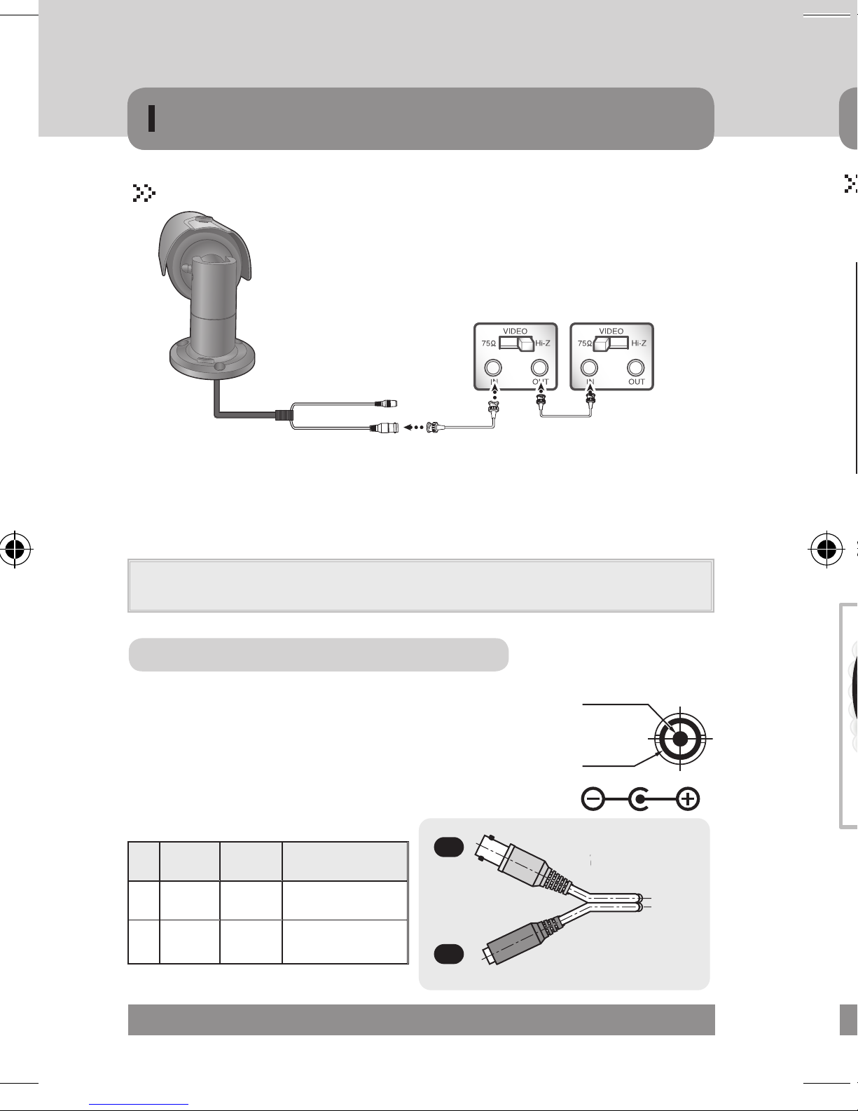
MDC-6xxx
• There are three ~ four mounting holes on the bracket so that users can install the
unit in any place such as on the ceiling, On the wall, on the fence and etc.
• Fix the camera on the bracket.
• Please check the points below before connecting video & power cable.
• Adjust picture direction pan & tilt
Caution!
To avoid smear, never face the camera directly to the
strong light source such as sun or spot light.
3 AXIS BRACKET
3 AXIS BRACKET
• Open the dome with the ring unscrewed.
• There are two mounting holes on the dome base so that users can install the unit
• The mounting in any place connecting the video/power cable, before connecting
• Adjust picture direction pan & tilting.
• Close the dome with the ring screwed.
65ø TYPE
70 / 90ø TYPE
32 MICRODIGITAL
77 / 88ø TYPE
MOUNTING SCREW MOUNTING SCREW
MOUNTING SCREW
CABLE MANAGEMENT BRACKET
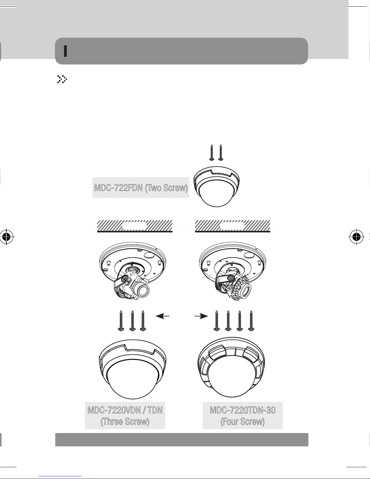
INSTALLATION
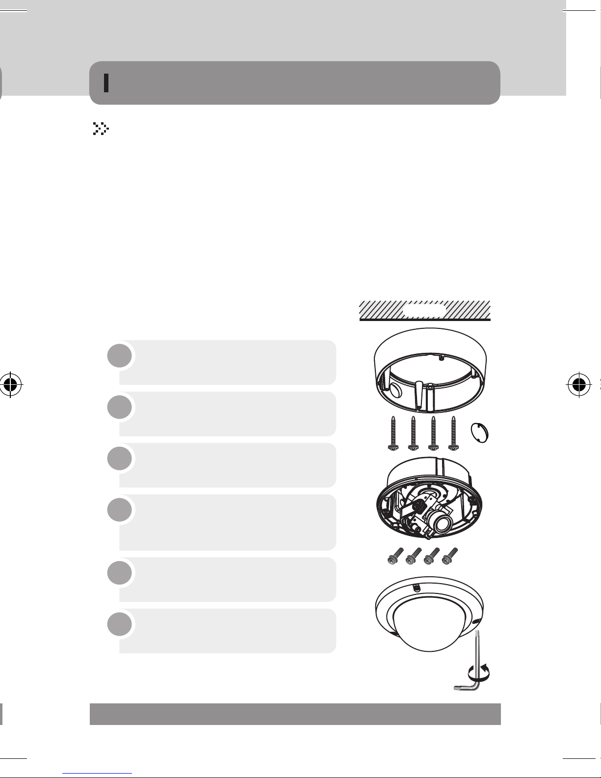
MDC-7xxx
• Open the dome with the ring unscrewed.
• There are two mounting holes on the dome base so that users can install the unit
in any place such as on the ceiling, on the wall, on the fence and etc.
• The mounting in any place connecting the video/power cable, before connecting
please check the below point.
• Adjust picture direction pan & tilting.
• Close the dome with the ring screwed.
MDC-722FDN (Two Screw)
Ceiling Ceiling
MDC-7220VDN / TDN
BASE HOUSING
MOUNTING SCREW
DOME COVER
HOLDER
DOME COVER
MDC-7220TDN-30
(Three Screw)
(Four Screw)
MICRODIGITAL 33
Draw out power / video wires
to the connecting places.
Fixed the camera to a celling
using four screws.
Adjust desired focus and scene
by turning and moving the
3-axis camera bracket by hand.
Put the dome cover over the
base.
Fix the dome cover on the base
by L-Wrench.
1
2
3
4
5
Draw out power / video wires
to the connecting places.
2
Fix the surface mount bracket
by screws on the ceiling.
1
Adjust desired focus and scene
by turning and moving the
3-axis camera bracket by hand.
4
Put the dome cover over the
base.
5
Fix the dome cover on the base
by L-Wrench.
6
Connect the dome base to the
surface mount bracket by screws.
3
Ceiling
INSTALLATION
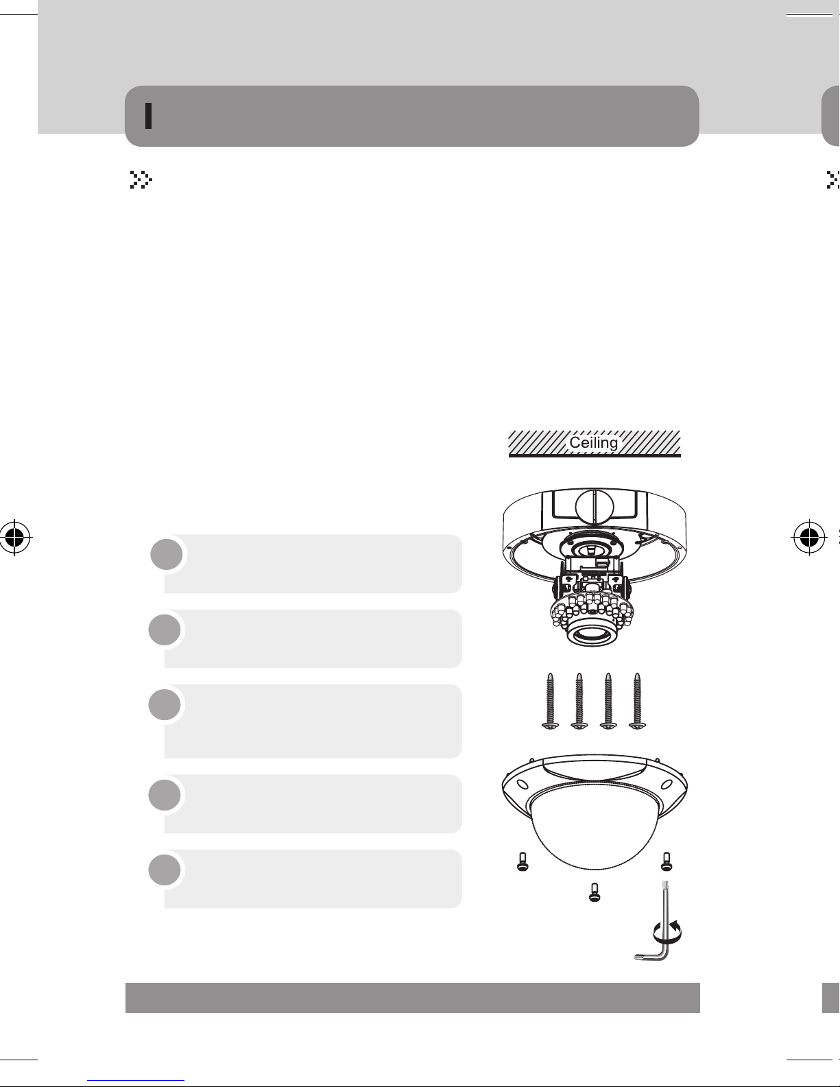
MDC-8xxx
• Open the dome cover on the base by L-Wrench.
• Remove the tapping screw on the dome camera base by screw driver.
▶ Surface type
· Fixed the surface mount bracket to a ceiling using three mounting screw.
· Draw out power/video wires to the connecting places.
· Insert dome camera base into the surface mount bracket.
· Fixed the dome camera base to a surface mount
bracket using three tapping screw.
▶ Flush type
· Remove the surface mount bracket then insert dome camera base into
the drilled holes.
· Draw out power/video wires to the connecting places.
· Fixed the dome camera base to a ceiling using three mounting screw.
• Adjust desired focus and scene by turning and moving 3-axis by hand.
• Close the dome cover on the base by L-Wrench.
34 MICRODIGITAL
Draw out power / video wires
to the connecting places.
2
Fix the surface mount bracket
by screws on the ceiling.
1
Adjust desired focus and scene
by turning and moving the
3-axis camera bracket by hand.
4
Put the dome cover over the
base.
5
Fix the dome cover on the base
by L-Wrench.
6
Connect the dome base to the
surface mount bracket by screws.
3
Ceiling
INSTALLATION
MDC-8xxx
▶ Flush type
· Remove the surface mount bracket then insert dome camera base into
the drilled holes.
· Draw out power/video wires to the connecting places.
· Fixed the dome camera base to a ceiling using three mounting screw.
• Adjust desired focus and scene by turning and moving 3-axis by hand.
• Close the dome cover on the base by L-Wrench.
MICRODIGITAL 35
OSD OPERATION
MDC-4xxx
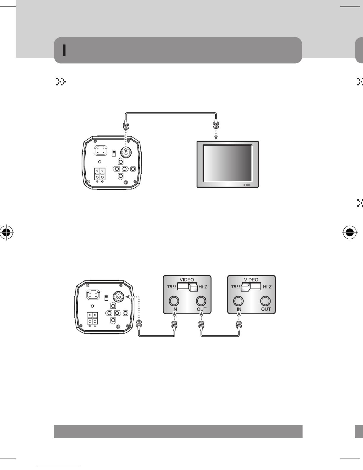
1) Connection to Monitor
Camera
IRIS JACK
2
1
43
POWER
AC 24V IN
DC 12V IN
DC
VIDEO
VIDEO OUT
SET
F.G
- As the connecting method varies with the instruments, refer to the manual sup-
plied with the instrument.
- If necessary, you can connect the monitor to the REMOTE jack on the back of
your camera.
- Only connect the cable when the power is furned off.
- Set the 75Ω / Hi-Z selection switch as shown below if you have an
intermediate device.
Monitor
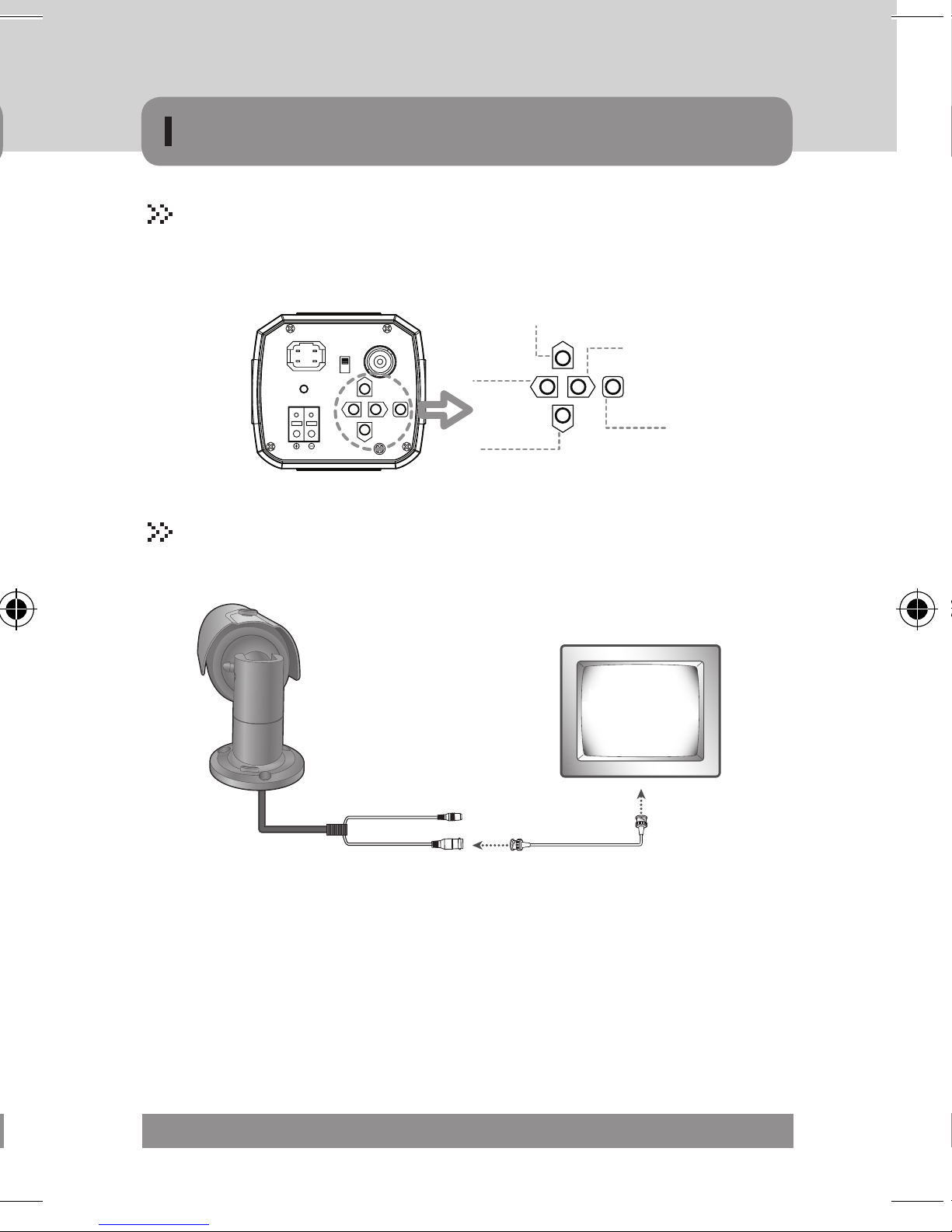
Settings can be made using the 4 or 5 buttons located on the nearby of the camera.
1) Connection to Monitor
IRIS JACK
2
1
43
POWER
AC 24V IN
DC 12V IN
DC
VIDEO
VIDEO OUT
SET
F.G
2) Connection to Power
- Connect the adaptor to the power input connector as shown in the following
figure. The Standard voltage for camera option : DC 12V± 10%, AC 24V ±10%.
36 MICRODIGITAL
- As the connecting method varies with the instruments, refer to the manual sup-
plied with the instrument.
- If necessary, you can connect the monitor to the REMOTE jack on the back of
your camera.
- Only connect the cable when the power is furned off.
- Set the 75Ω / Hi-Z selection switch as shown below if you have an
intermediate device.
Camera
OSD OPERATION
Settings can be made using the 4 or 5 buttons located on the nearby of the camera.
IRIS JACK
2
1
43
POWER
AC 24V IN
DC 12V IN
DC
VIDEO
VIDEO OUT
SET
F.G
MDC-6xxx
1) Connection to Monitor
UP
LIGHT
LEFT
SET
SET
DOWN
t
- As the connecting method varies with the instruments, refer to the manual supplied with the instrument.
- If necessary, you can connect the monitor to the REMOTE jack on the back of
your camera.
- Only connect the cable when the power is furned off.
- Set the 75Ω / Hi-Z selection switch as shown below if you have an
intermediate device.
Power Input
MICRODIGITAL 37
o
ellow)
V
)
Push(set)
OSD OPERATION
MDC-6xxx
G
Power Input
2) Connection to Power
- Connect the adaptor to the power input connector as shown in the following figure.
The Standard voltage for camera option : DC 12V± 10%, AC 24V ±10%.
NOTE
▪ Nomal we donnot use the RS-485 addisional cable. only have power and video
Connecting to Monitor and Power
For 12V DC Power Type
- Connect the video-out jack to the video-in jack of monitor.
- Connect the power adapter to the power input connecter.
- Use 12V DC power source.
- Use the power rated at least 400mA (12VDC)
#
NO Function
Video
#1
Output
Power
#2
Input
Terminal
Color
Yellow 1.0 Vp-p
Red
Remark
12V DC(10V~15V),
Max 4.8W / 400mA
1
#
2
Video Output
GND
e
Video
(Yellow)
ower - DC 12
Power - DC 12V
Red
(Red)
MDC-6220TDN-20 / 20H
♦ Unscrew the front cover
38 MICRODIGITAL

OSD OPERATION
MDC-6xxx
Push(set)
MDC-6220TDN
-35H, 36H, 45, 48
MDC-6220TDN-20 / 20H
♦ Unscrew the front cover
♦ Unscrew the OSD button cap
MDC-6220TDN
-24H, 42, 30, 40H
♦ Unscrew the front cover
MICRODIGITAL 39
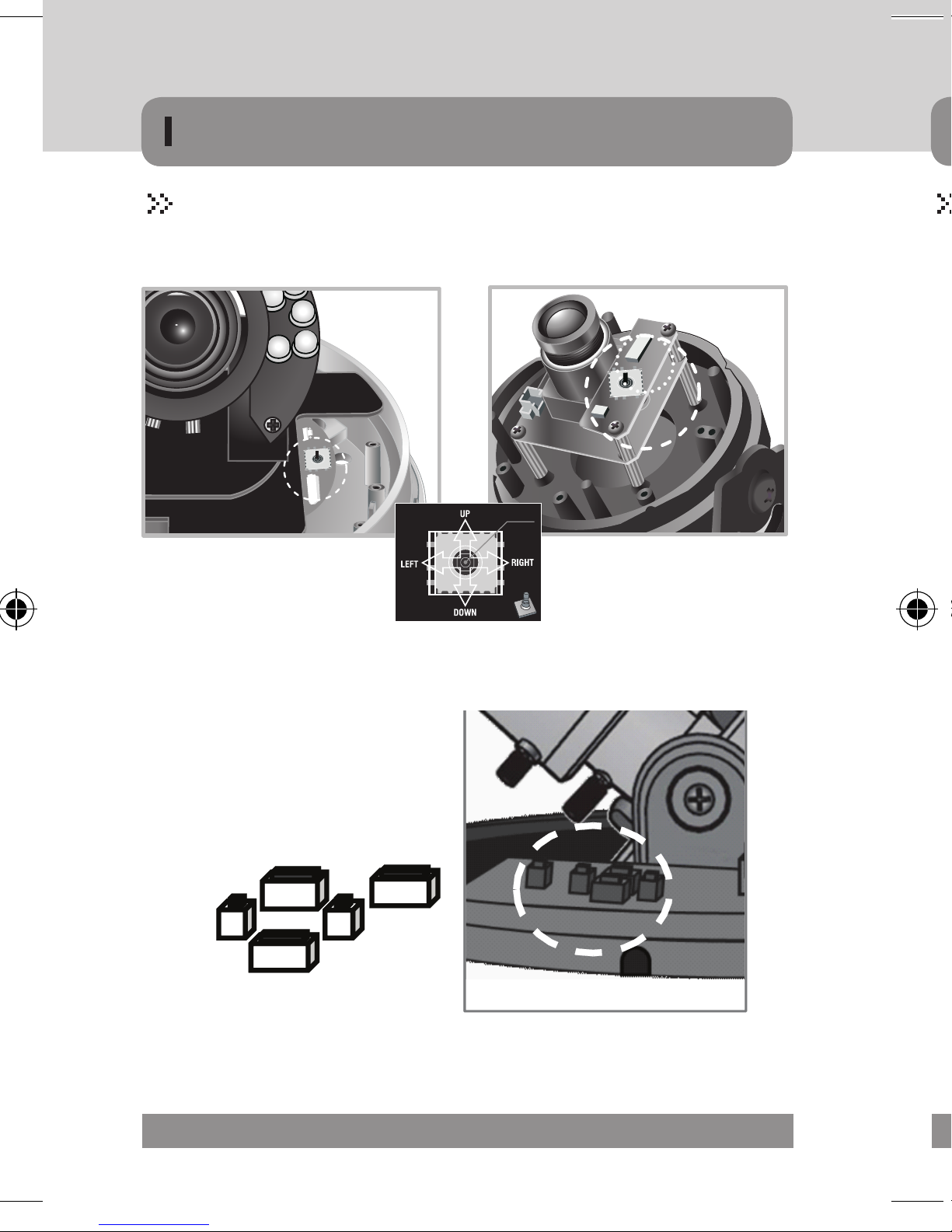
OSD cable
co nnecter
VBS-Extra
on n ector
OSD button
OSD button
Temperature
Sensor
VBS-Extra
co nnecter
OSD cable
co nnecter
Power OSD
co nnector
OSD Module
co nnector
OSD OPERATION
MDC-7xxx
Without Heater type OSD Board
Push(set)
MDC-7220FDN / 7220TDN-30 (OSD JOYSTICK)
♦ Unscrew the dome cover
UP
LEFT
RIGHT
SET
C
With Heater type OSD Board
DOWN
MDC-7220VDN / TDN (OSD BOARD)
♦ Unscrew the dome cover
40 MICRODIGITAL

Power OSD
OSD OPERATION
MDC-8xxx
Without Heater type OSD Board
OSD cable
co nnecter
VBS-Extra
Con n ector
OSD button
With Heater type OSD Board
OSD Module
co nnector
co nnector
VBS-Extra
co nnecter
OSD cable
co nnecter
Temperature
Sensor
OSD button
MICRODIGITAL 41

OSD OPERATION
UTC CONTROLLER
▶CONNECTION
▪Camera(BNC) ➜Remote Controller ➜ BNC ➜ Monitor / DVR
▹ SET button
• Used for the menu display. This button can be used to confirm settings after
Remote Controller
DVD
BNC
CON NECTOR
Rem ote Controller
Monit or / DVR
▶UTC Specification
Content Spec Remark
Support VIDEO format NTSC / PAL
Video Input Level 1.0 Vp-p / 75 Ohm BNC
Video Output Level 1.0 Vp-p / 75 Ohm BNC
Control OSD, PAN/Focus
Compatibility
Distance Video Output Distance TEST : 500M (RG59)
Operation temperature -20°C ~ +60°C Standard
MicroDigital
Except Other Companies
UTC Product Family
▹ UP & DOWN buttons
• Used for selecting items by moving the cursor up or down on the menu screen.
▹ LEFT & RIGHT buttons
• Used when changing item values, by moving the cursor to the left or right on the
Setting
▹ Use the OSD control switch on the main body of the camera
▹ Settings can be made using the 5 buttons located on the rear
▹ Press the set switch
• The [SETUP] menu appears on the monitor screen
• Use UP and DOWN switch to select menu, then press SET switch ( )
· Submenu appears on monitor screen
• Set up selected item by using the LEFT and RIGHT switch ( )
• To finish and save the settings, select [EXIT] and press the SET button ( )
Dimension (W x D x H) 55 x 85 x 10 (mm)
Power CR2032 X 2 Battery
• Features
▪Long distance controller.
▪Menu can be adjusted without opening the camera case.
▪User can adjust OSD control during installation without the portable monitor.
▪It is of conveniently portable size.
42 MICRODIGITAL
NOTE
▪ An item with the ↵ icon also has sub-menus. To select a sub-menu, press the
▪ An item with the - - - icon has no sub-menus available for selection

INSTRUCTIONS
OSD(On Screen Display) Button
▹ SET button
• Used for the menu display. This button can be used to confirm settings after
changing the value of the selected function or current conditions.
▹ UP & DOWN buttons
• Used for selecting items by moving the cursor up or down on the menu screen.
▹ LEFT & RIGHT buttons
• Used when changing item values, by moving the cursor to the left or right on the
menu screen.
Setting
▹ Use the OSD control switch on the main body of the camera
▹ Settings can be made using the 5 buttons located on the rear
of the camera
▹ Press the set switch
• The [SETUP] menu appears on the monitor screen
• Use UP and DOWN switch to select menu, then press SET switch ( )
· Submenu appears on monitor screen
• Set up selected item by using the LEFT and RIGHT switch ( )
• To finish and save the settings, select [EXIT] and press the SET button ( )
NOTE
▪ An item with the ↵ icon also has sub-menus. To select a sub-menu, press the
SET button.
▪ An item with the - - - icon has no sub-menus available for selection
MICRODIGITAL 43

OSD STRUCTURE
Function Menu Structure
LENS
EXPOSURE
WHITE BAL.
DAY/NIGHT
3D DNR
■ DC / VIDEO / MANUAL
■ SHUTTER
• 1/50~1/100K / x2~x256 /AUTO / FLK
■ AGC
• LOW / MIDDLE / HIGH
■ SENS-UP
• AUTO / OFF
■ ATW / AWB / MANUAL / AWC --->SET / INDOOR / OUTDOOR
■ AUTO / B/W / COLOR / EXT
■ ON(RANGE : 0~100 LEVEL SELECTABLE)/OFF
■ CAMERA TITLE : ON/OFF ■ SYNC : INT
■ D-EFFECT
• FREEZE / MIRROR / D-ZOOM /
GAMMA / NEG.IMAGE / RETURN
■ BLC
• OFF / BLC / HSBLC
■ D-WDR
• OFF / INDOOR / OUTDOOR
■ RETURN
■ LANGUAGE
• ENG / KOR / JPN / CHN1 /
CHN2 / RUS
▹ This function is Control brightness of the screen
• DC : select auto iris lens
· The brightness of the screen can be adjusted in DC mode.
· The brightness can be adjusted within the range of 0 ~100.
· The optimum level of brightness can be achieved using this adjustment.
• Video : select video lens
• Manual : select manual lens
■ RS 485
• CAM ID / ID-DISPLAY / BAUDRATE
SPECIAL
■ MOTION
• AREA SELECT(4ch) / AREA
■ PRIVACY
• AREA SELECT(8ch) / AREA
■ SHARPNESS : 0 ~ 31 ■ MONITOR : CRT / LCD / USER
ADJUST
■ OSD COLOR : 0 ~ 15 ■ RETURN
RESET
EXIT
■ FACTORY DEFAULT ■ RETURN
■ SAVE SET UP MENU AND EXIT
44 MICRODIGITAL
DISPLAY / SENSITIVITY / MOTION
VIEW / RETURN
DISPLAY / COLOR / RETURN
■ DEFECT
• SENS-UP / DIFF / START / RETURN
■ RETURN
NOTE
▪ If you press the Set button in "MANUAL LENS", You can Adjust brightness in
▪ If you press the Set button in "VIDEO", You can't adjust brightness in EXPO-

OSD STRUCTURE-MAIN MENU
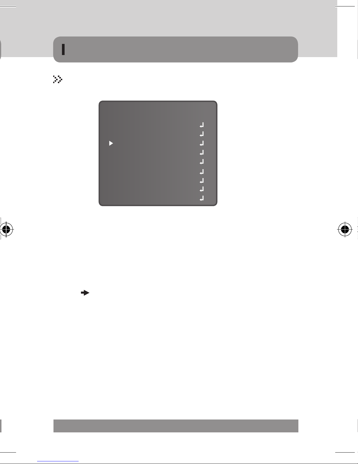
LENS
▹ This function is Control brightness of the screen
• DC : select auto iris lens
· The brightness of the screen can be adjusted in DC mode.
· The brightness can be adjusted within the range of 0 ~100.
· The optimum level of brightness can be achieved using this adjustment.
• Video : select video lens
• Manual : select manual lens
SETUP
LENS
EXPOSURE
WHITE BAL.
DAY & NIGHT
3DNR
SPECIAL
ADJUST
RESET
EXIT
DC
ATW
AUTO
ON
BRIGHTNESS
RETURN
LENS
40
RET
NOTE
▪ If you press the Set button in "MANUAL LENS", You can Adjust brightness in
EXPOSURE.
▪ If you press the Set button in "VIDEO", You can't adjust brightness in EXPO-
SURE, Return to "LENS" and adjust lens type
MICRODIGITAL 45

OSD STRUCTURE-MAIN MENU
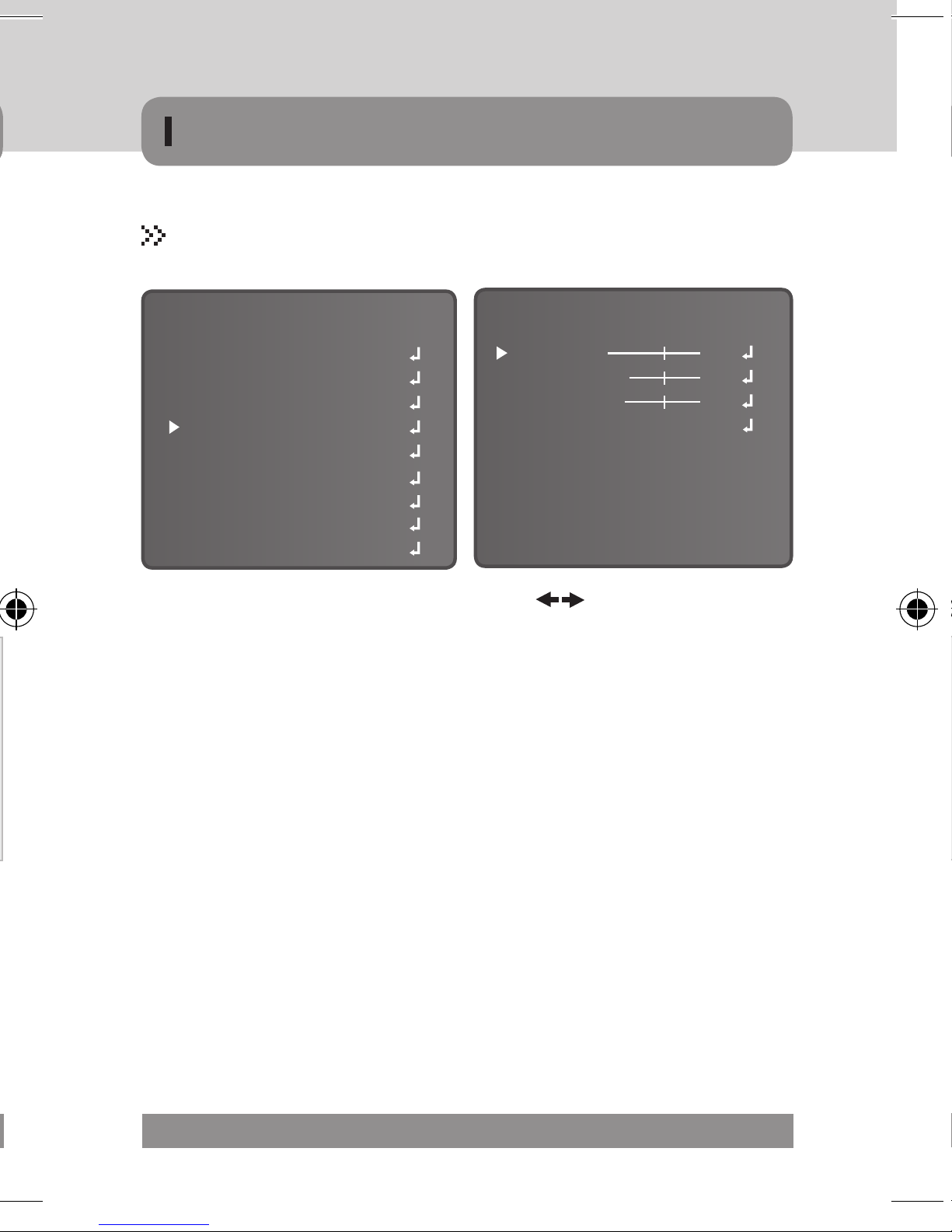
EXPOSURE
▹ This function is used to select Automatic or Manual shutter
speed control
▶ SENS-UP
• When it is night or even under low level, the camera automatically detects the
· AUTO, OFF can be selected ( )
SETUP
LENS
EXPOSURE
WHITE BAL.
DAY & NIGHT
3DNR
SPECIAL
ADJUST
RESET
EXIT
DC
ATW
AUTO
ON
SHUTTER
AGC
SENS-UP
BLC
D-WDR
RETURN
EXPOSURE
1/50
MIDDLE
AUTO
OFF
OFF
RET
▶ SHUTTER
• The shutter speed is controlled manually.
· Use OSD button to set shutter speed
» (1/50~1/100K / x2~x256 / AUTO / FLK, )
NOTE
▪ Select 'FLK' mode when flickering occurs on the screen due to an imbalance
between illumination and frequency. (NTSC Model : 1/100, PAL Model : 1/120)
» AUTO : Activates the SENS-UP function.(x2 ~ x256)
» OFF : Deactivates the SENS-UP function.
▶ BLC (Back Light Compensation)
• When there is a strong backlight behind the object, clear images of the
· OFF / BLC / HSBLC can be selected ( )
• HSBLC (Highlight Suppress Back Light Compensation)
· If there is a high light installed in a limited environment such as a parking
» Select the desired mode using the OSD buttons and press the SET button.
▶ AGC (AUTO GAIN CONTROL)
• If the images are too dark, change maximum "AGC" value to make the images
lighter LOW, MIDDLE, HIGH can be selected
NOTE
▪ The higher the gain level, the brighter the screen - but the higher the noise.
46 MICRODIGITAL

OSD STRUCTURE-MAIN MENU
▶ SENS-UP
• When it is night or even under low level, the camera automatically detects the
light level and maintains a clear picture if this mode is activated.
· AUTO, OFF can be selected ( )
» AUTO : Activates the SENS-UP function.(x2 ~ x256)
» OFF : Deactivates the SENS-UP function.
▶ BLC (Back Light Compensation)
• When there is a strong backlight behind the object, clear images of the
background as well as the object can still be obtained by using the BACKLIGHT
function.
· OFF / BLC / HSBLC can be selected ( )
• HSBLC (Highlight Suppress Back Light Compensation)
· If there is a high light installed in a limited environment such as a parking
garage or gas station entrance, removing the high light makes it possible to
view car license plates efficiently.
» Select the desired mode using the OSD buttons and press the SET button.
HSBLC ON
HSBLC OFF
MICRODIGITAL 47

OSD STRUCTURE-MAIN MENU
▶D – WDR (Digital Wide Dynamic Range)
• By D-WDR image processing techniques of input image, information of input im-
age brightness value is analyzed. The part of relatively bright and dark images is
judged and through different Brightness value mapping you will have the effect
of Improving the contrast ratio.
· OFF, INDOOR, OUTDOOR can be selected ( )
» When there are simultaneous brightness & dark image areas at the same time
WDR makes both clear and you can select desired feature between OUTDOOR
and INDOOR.
· OFF : D-WDR function does not operate.
NOTE
▪ Please select INDOOR and OUTDOOR to fit the individual environments.
▶ RETURN
• RETURN
· Save the changes and complete the setup, return to previous menu
▹ The White Balance function is used to adjust the screen colors.
▶ ATW (Auto Tracking White Balance)
• This mode can be used within the color temperature range 1,800°K ~ 10,500°K
▶AWB(Automatic White Balance)
• The White Balance is automatically adjusted in a specific environment
• END
· Save the changes and complete the setup, return to display
48 MICRODIGITAL
▶AWC SET
• To obtain the optimum state under the current luminance levels, direct the camera
▶INDOOR
• Select this when the color temperature is between 4,500°K ~8,500°K
▶OUTDOOR
• Select this when the color temperature is between 1,800°K ~ 10,500°K.
(sodium light inclusion)
OSD STRUCTURE-MAIN MENU
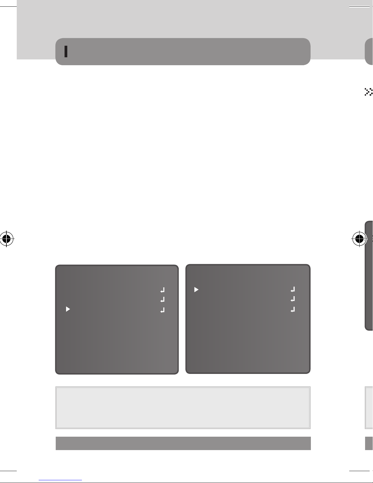
WHITE BALANCE
▹ The White Balance function is used to adjust the screen colors.
SETUP
LENS
EXPOSURE
WHITE BAL.
DAY & NIGHT
3DNR
SPECIAL
ADJUST
RESET
EXIT
ATW
AUTO
DC
ON
▶ ATW (Auto Tracking White Balance)
• This mode can be used within the color temperature range 1,800°K ~ 10,500°K
▶AWB(Automatic White Balance)
• The White Balance is automatically adjusted in a specific environment
▶AWC SET
• To obtain the optimum state under the current luminance levels, direct the camera
to point toward a sheet of white paper and press the SET button. If the environment
changes, including the light source, the white balance will require re-adjustment.
▶INDOOR
• Select this when the color temperature is between 4,500°K ~8,500°K
▶OUTDOOR
• Select this when the color temperature is between 1,800°K ~ 10,500°K.
(sodium light inclusion)
MICRODIGITAL 49
OSD STRUCTURE-MAIN MENU
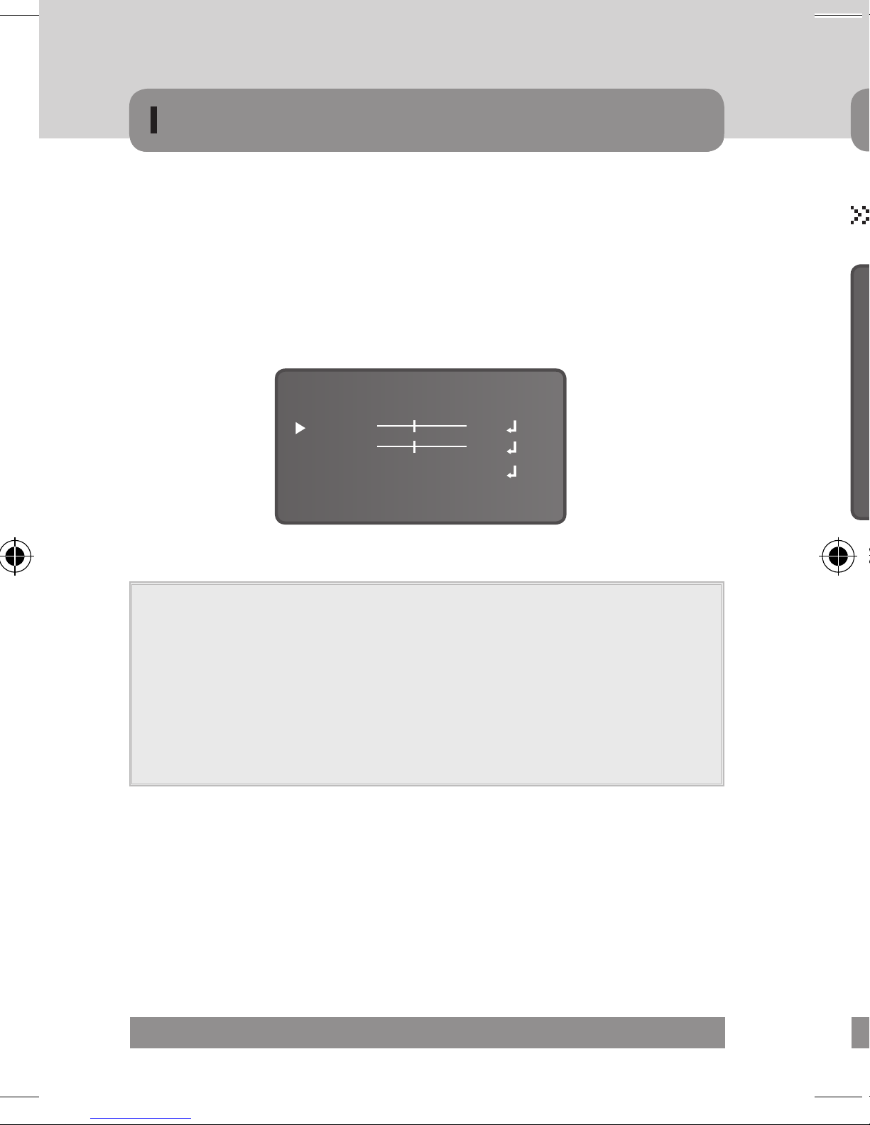
▶MANUAL
• Used for fine adjustment of White Balance.
· Set White Balance first using ATW or AWC then change to MANUAL and press
SETUP button. Increase or decrease the value of R-Gain(Red) and B-Gain(Blue)
while monitoring the color of the image.
WHITE BALANC MANUAL
BLUE
RED
RETURN
50
50
RET
NOTE
▪ Under the following conditions White Balance may not work properly. In such
cases, select the AWC mode.
1. When the color temperature of the subject environment has a very high tempera-
ture range (e.g. clear sky, or sunset)
2. When the ambient illumination of the subject is low.
3. If the camera is directed toward a fluorescent light, or is installed in a place
where illumination changes dramatically, the White Balance operation may become unstable.
▹ Pictures can be displayed in either color or B/W.
• Select a desired mode using the OSD buttons .( )
▶ COLOR
· The picture is always displayed in color.
▶ AUTO
· The mode is automatically switches to COLOR in normal conditions and switches
» DELAY : You can control the filter change delay time 0 ~ 63.
» Day ➜ Night (AGC) : adjust the filter change point (0 ~ 173)
50 MICRODIGITAL
» Night ➜ Day (AGC) : adjust the filter change point (0 ~ 173)
▶ EXTERN (External)
· This mode allows the application of a filter to external signals.
OSD STRUCTURE-MAIN MENU
DAY & NIGHT
▹ Pictures can be displayed in either color or B/W.
SETUP
LENS
EXPOSURE
WHITE BAL.
DAY & NIGHT
3DNR
SPECIAL
ADJUST
RESET
EXIT
DC
ATW
AUTO
ON
DAY & NIGHT AUTO
DELAY
D → N (AGC)
N → D (AGC)
RETURN
176
RET
5
76
• Select a desired mode using the OSD buttons .( )
▶ COLOR
· The picture is always displayed in color.
▶ AUTO
· The mode is automatically switches to COLOR in normal conditions and switches
to B/W mode when ambient illumination is low.
» DELAY : You can control the filter change delay time 0 ~ 63.
» Day ➜ Night (AGC) : adjust the filter change point (0 ~ 173)
» Night ➜ Day (AGC) : adjust the filter change point (0 ~ 173)
▶ EXTERN (External)
· This mode allows the application of a filter to external signals.
MICRODIGITAL 51
OSD STRUCTURE-MAIN MENU
▶ B/W (Black/White) : The picture is always displayed in black / white
• BURST : You can control the burst.
• IR SMART : It enables users to distinguish the indistinguishable images saturated
by IR LED.
» GAIN : You can adjust the degree of the brightness of IR LED.
» AREA : You can adjust the area.
- POSITION : Move the arrow indicator to the LEFT / RIGHT and TOP / BOTTOM
to select the desired area position by using the OSD buttons.
- SIZE : Move the arrow indicator to select the WIDTH and HEIGHT of cells to
increase or decrease by using the OSD buttons.
» RET / AGAIN
- RETURN : Save the changes and complete the setup, return to previous menu
- AGAIN : reset the position and size menu
• RETURN : Select this to save the setting for the ‘D&N B/W’ menu
DAY & NIGHT B/W
IR SMART
▹ 3D-DNR is used to reduce the level of background noise in a low luminance
▶ Select a desired mode using the OSD buttons. ( ) you can get clean
• OFF : Deactivates 3D-DNR. Noise is not reduced.
• ON : Activates 3D-DNR so that noise is reduced.
▶ Set the DNR mode to 'ON' and press the SET button.
▶ The noise reduction level can now be adjusted
BURST
IR SMART
RETURN
OFF
OFF
RET
GAIN
AREA
RETURN
NOTE
▪ Smart-IR function is available to use for camera with IR LED only.
▪ It controls the IR LED(bright portion base), situation is not expected.
=> This function can be utmost only at BURST OFF.
52 MICRODIGITAL
OFF
OFF
RET
NOTE
▪ When adjusting the noise reduction level in DNR mode, Remember that

OSD STRUCTURE-MAIN MENU
3D-DNR
▹ 3D-DNR is used to reduce the level of background noise in a low luminance
environment.
▶ Select a desired mode using the OSD buttons. ( ) you can get clean
images.
• OFF : Deactivates 3D-DNR. Noise is not reduced.
• ON : Activates 3D-DNR so that noise is reduced.
▶ Set the DNR mode to 'ON' and press the SET button.
▶ The noise reduction level can now be adjusted
SETUP
LENS
EXPOSURE
WHITE BAL.
DAY & NIGHT
3DNR
SPECIAL
ADJUST
RESET
EXIT
DC
ATW
AUTO
ON
LEVEL
RETURN
3DNR
RET
NOTE
▪ When adjusting the noise reduction level in DNR mode, Remember that
the higher the level is set the greater the reduction in noise level but it also
increases the possibility of ghosting.
50
MICRODIGITAL 53
OSD STRUCTURE-MAIN MENU
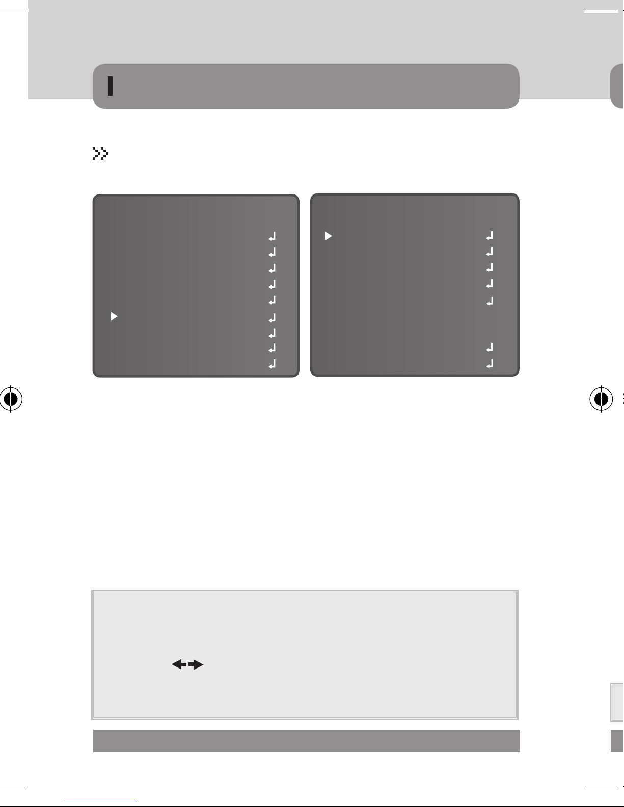
SPECIAL
▹ Special Add-ons
▶ D-EFFECT
• Move the cursor to D-EFFECT and
press the SET button to set the other
SETUP
LENS
EXPOSURE
WHITE BAL.
DAY & NIGHT
3DNR
SPECIAL
ADJUST
RESET
EXIT
DC
ATW
AUTO
ON
CAM TITLE
D-EFFECT
RS-485
MOTION
PRIVACY
SYNC
LANGUAGE
DEFECT
RETURN
SPECIAL
▶ CAM TITLE
• When input, the Camera Title is displayed on the monitor.
· Set to 'ON' using the Left and Right buttons. And press SET button.
· Choose a character using the OSD buttons. And the press SET button.
• Change the "CAM TITLE" Position.
· Use OSD buttons. Move the cursor by POS and press the SET button.
OFF
OFF
OFF
INT
ENG
RET
image functions.
• FREEZE
· View freezing Image or moving Image
• MIRROR
· MIRROR, V-FLIP, ROTATE can be selected.
» MIRROR : Flip the image horizontally on the screen.
» V-FLIP : Flip the image vertically on the screen.
» ROTATE : Flip the horizontal image vertically on the screen.
» OFF : Disabled.
• D – ZOOM
· Digital zoom available, OFF(x1) / ON(x2~x32) can be selected
» PAN : The pan range can be controlled between -100~+100
» TILT : The tilt range can be controlled between -100~+100
· Select a new position by using the OSD buttons, Press the SET button to confirm
the position.
NOTE
▪ Only English is available in the mode
▪ The CAMERA TITLE can be up to 15 alphanumeric characters in length.
▪ If used the CLS menu, all the letters are deleted
▪ Choose a ( ) menu using the OSD buttons. And the press set button.
Move the cursor over the letter to be edited, move the cursor to the letter to be
inserted and then press the SET button
54 MICRODIGITAL
• NEG.IMAGE
·NEGATIVE IMAGE or POSITIVE IMAGE can be selected.
NOTE
▪ PAN and TILT function should be available when using the digital zoom.
OSD STRUCTURE-MAIN MENU
▶ D-EFFECT
• Move the cursor to D-EFFECT and
press the SET button to set the other
image functions.
• FREEZE
· View freezing Image or moving Image
• MIRROR
· MIRROR, V-FLIP, ROTATE can be selected.
» MIRROR : Flip the image horizontally on the screen.
» V-FLIP : Flip the image vertically on the screen.
FREEZE
MIRROR
D-ZOOM
NEG. IMAGE
RETURN
D-EFFECT
OFF
OFF
OFF
OFF
RET
» ROTATE : Flip the horizontal image vertically on the screen.
» OFF : Disabled.
• D – ZOOM
· Digital zoom available, OFF(x1) / ON(x2~x32) can be selected
» PAN : The pan range can be controlled between -100~+100
» TILT : The tilt range can be controlled between -100~+100
D - ZOOM
D-ZOOM
PAN
TILT
RETURN
• NEG.IMAGE
·NEGATIVE IMAGE or POSITIVE IMAGE can be selected.
X 1.0
-10
0
RET
NOTE
▪ PAN and TILT function should be available when using the digital zoom.
MICRODIGITAL 55
OSD STRUCTURE-MAIN MENU
▶RS-485
• This function sets up the camera communication status when controlling the
camera through an external device.
RS-485
CAM ID
ID DISPLAY
BAUDRATE
RETURN
· CAM ID
» Determines the camera's identification number. (between 0 and 255).
· ID DISPLAY
» Display the camera title on the top right corner of the screen.
- Use OSD buttons. Move the cursor by 'ON' and press the SET button.
( )
- Select a new position by using the OSD buttons, Press the SET button to
confirm the position
· BAUD RATE : Select 2400/4800/9600/19200/38400/57600 bps.
0
OFF
9600
RET
• AREA DISPLAY
· POSITION
» Move the arrow indicator to the
LEFT / RIGHT and TOP / BOTTOM
to select the desired area position
by using the OSD buttons.
( )
· SIZE
» Move the arrow indicator to select the WIDTH and HEIGHT of cells to increase or
· RET / AGAIN ( )
» RETURN
- Save the changes and complete the setup, return to previous menu
» AGAIN
- reset the position and size menu
• SENSITIVITY
· Adjust the level of observation (between 0 ~ 40)
▶ MOTION
• This product has a feature that allows you to observe movements of objects in 4
different areas on the screen. And the green shape appears. on the screen when
movement is detected, hence a single individual can conduct supervision
efficiently. The camera detects an
MOTION
object's movement by sensing
disparity of outline and level of
brightness and color.
• AREA SELECT
· Determines whether the [Motion
Detect area] selected (AREA 1 ~ 4)
56 MICRODIGITAL
AREA SELECT
AREA DISPLAY
SENSITIVITY
MOTION VIEW
RETURN
AREA 1
ON
40
ON
RET
• MOTION VIEW
· Able to check the sensing scene of motion detection in the screen
(the green shape appears)
• RETURN
· RETURN
» Save the changes and complete the setup, return to previous menu
· END
» Save the changes and complete the setup, return to display
NOTE
▪ Change the selected area only
▪ Use SET button to change the menu
OSD STRUCTURE-MAIN MENU
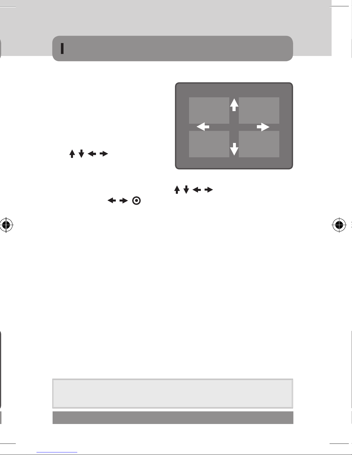
• AREA DISPLAY
· POSITION
» Move the arrow indicator to the
LEFT / RIGHT and TOP / BOTTOM
to select the desired area position
by using the OSD buttons.
( )
· SIZE
» Move the arrow indicator to select the WIDTH and HEIGHT of cells to increase or
decrease by using the OSD buttons. ( )
· RET / AGAIN ( )
» RETURN
POSITION
- Save the changes and complete the setup, return to previous menu
» AGAIN
- reset the position and size menu
• SENSITIVITY
· Adjust the level of observation (between 0 ~ 40)
• MOTION VIEW
· Able to check the sensing scene of motion detection in the screen
(the green shape appears)
• RETURN
· RETURN
» Save the changes and complete the setup, return to previous menu
· END
» Save the changes and complete the setup, return to display
NOTE
▪ Change the selected area only
▪ Use SET button to change the menu
MICRODIGITAL 57

OSD STRUCTURE-MAIN MENU
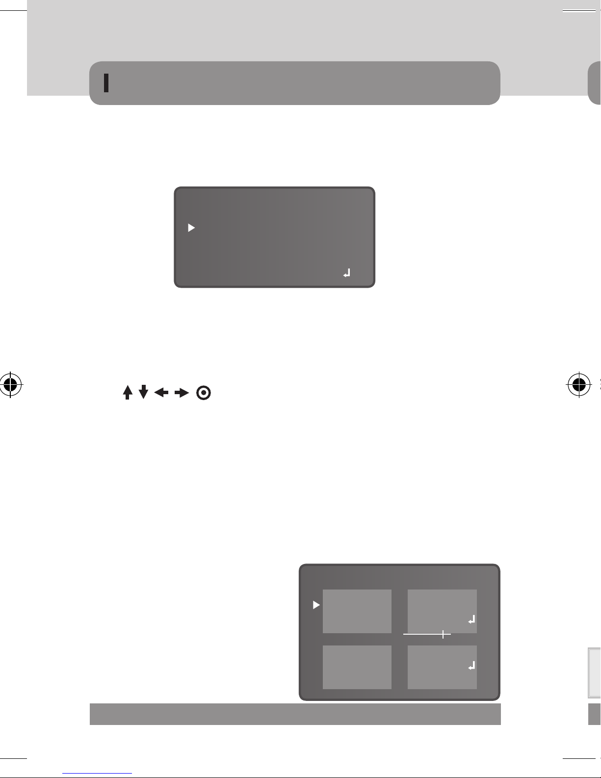
▶ PRIVACY
• Hide an area you want to hide on the screen
PRIVACY
▶
• INT (Internal Synchronization)
AREA SELECT
AREA DISPLAY
COLOR
RETURN
AREA 1
ON
15
RET
POSITION
• AREA SELECT
· Determines whether the [Motion Detect area] selected (AREA 1 ~ 8)
• AREA DISPLAY
·
POSITION
» Move the arrow indicator to the LEFT/RIGHT and TOP/BOTTOM to select the
desired area position by using the OSD buttons. ( )
·
SIZE
» Move the arrow indicator to select the WIDTH and HEIGHT of cells to increase or
decrease by using the OSD buttons . ( )
·
RET / AGAIN
» RETURN : Save the changes and complete the setup, return to previous menu
▶ LANGUAGE
• English, Korean, Japanese, China 1, China 2, Russia
▶ DEFECT : White defect Check and compensation
• When the camera becomes hot after operating a couple of days, white spots
· SENS-UP
» SENS-UP level can be selected (between x4, x8, x16, x32, x64)
· DIFF
» Check level can be selected (between 1~6)
· START
» start the defect function
· RETURN
» RETURN
» AGAIN : resetting the position and size menu
• COLOR : Possible to choose a color of the privacy area. (0 ~ 15)
• RETURN
·
RETURN
» Save the changes and complete the setup, return to top menu
·
END
» Save the changes and complete the setup, return to display
NOTE
▪ Change the selected area only
▪ Use SET button to change the menu
58 MICRODIGITAL
- Save the changes and complete the setup, return to previous menu
» END
- Save the changes and complete the setup, return to display Press
» "SET" button. ( )

OSD STRUCTURE-MAIN MENU
▶ SYNC
• INT (Internal Synchronization)
▶ LANGUAGE
• English, Korean, Japanese, China 1, China 2, Russia
▶ DEFECT : White defect Check and compensation
• When the camera becomes hot after operating a couple of days, white spots
are shown on the screen especially at low light condition and they are recorded
together with normal image. By using this function, white spots are removed and
you can get clean images.
· SENS-UP
» SENS-UP level can be selected (between x4, x8, x16, x32, x64)
· DIFF
» Check level can be selected (between 1~6)
· START
» start the defect function
· RETURN
» RETURN
- Save the changes and complete the setup, return to previous menu
» END
- Save the changes and complete the setup, return to display Press
» "SET" button. ( )
MICRODIGITAL 59

OSD STRUCTURE-MAIN MENU
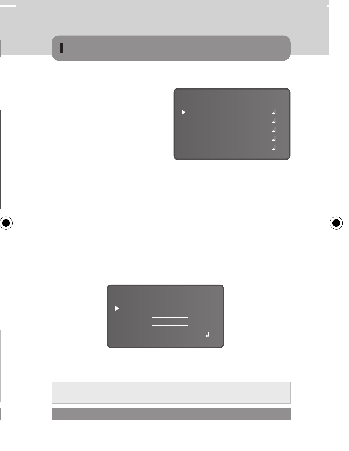
ADJUST
▹ Display Adjustment
SETUP
LENS
EXPOSURE
WHITE BAL.
DAY & NIGHT
3DNR
SPECIAL
ADJUST
RESET
EXIT
▶
SHARPNESS
ATW
AUTO
DC
ON
• As you increase this value, the picture outline becomes stronger and clearer.
The level can be adjusted to obtain an improved image.
• The sharpness of the image can be adjusted using the left and right buttons.
SHARPNESS
MONITOR
OSD COLOR
RETURN
ADJUST
20
CTR
7
RET
• LCD & USER
·
» Adjustable gamma value.
(between 0.05 ~ 1.00)
·
» Adjustable brightness and contrast
value. (between 0 ~ 63)
·
» Adjustable blue value. (between 0 ~ 100)
·
» Adjustable red value. (between 0 ~ 100)
▶ OSD COLOR
• Choose a display OSD color, using the OSD buttons. ( )
·
RESET
(between 0~31)
NOTE
▪ If the Sharpness level is set too high it can distort the image or cause noise
▶ MONITOR
• CRT
·
LEVEL
» Adjustable brightness and contrast
value. (between 0 ~ 63)
·
BLUE GAIN
» Adjustable blue value.
(between 0 ~ 100)
·
RED GAIN
»
Adjustable red value. (between 0 ~ 100)
60 MICRODIGITAL
MONITOR CRT
LEVEL
BLUE GAIN
RED GAIN
RETURN
35
60
60
RET
▶ FACTORY
• To reset your camera to factory default setting.
▶ EXIT
• Press the SET button in the EXIT
menu to save the current settings
and exit the SETUP menu.

OSD STRUCTURE-MAIN MENU
• LCD & USER
·
GAMMA
MONITOR LCD
» Adjustable gamma value.
(between 0.05 ~ 1.00)
·
LEVEL
» Adjustable brightness and contrast
value. (between 0 ~ 63)
·
BLUE GAIN
GAMMA
LEVEL
BLUE GAIN
RED GAIN
RETURN
» Adjustable blue value. (between 0 ~ 100)
·
RED GAIN
» Adjustable red value. (between 0 ~ 100)
▶ OSD COLOR
• Choose a display OSD color, using the OSD buttons. ( )
· between 0~15, default 9
RESET
▶ FACTORY
0.50
35
60
60
RET
• To reset your camera to factory default setting.
▶ EXIT
• Press the SET button in the EXIT
menu to save the current settings
and exit the SETUP menu.
LENS
EXPOSURE
WHITE BAL.
DAY & NIGHT
3DNR
SPECIAL
ADJUST
RESET
EXIT
SETUP
AUTO
MICRODIGITAL 61
DC
ATW
ON

MEMO
62 MICRODIGITAL

MENO
MICRODIGITAL 63

www.microdigital.co.kr
USER MANUAL
TOTAL SECURITYGSOLUTION
Design and specifications are subject to change without notice.
www.microdigital.co.kr
sales@microdigital.co.kr
#1212, Hoseodae Venture Tower,
319, Gasan-Dong, Geumcheon-Gu, Seoul, Korea
Supreme Resolution
Day & Night Color Camera
Ver.120103E
Tel :+82-2-2627-5279 / Fax :+82-2-2627-5295
P/N : 3690-0002A
 Loading...