

Page 1
User Manual of WirelessHART
Development Board
Microcyber Corporation
I
Page 2

Table of Contents
1. Terms, Abbreviations, and Explanations ......................................................................... 1
2. Preface ............................................................................................................................. 1
3. HardwareInterface Description of WH-M Development Board ....................................... 2
3.1 Structure Description of Development Board .............................................................. 2
3.2 Circuit Description ............................................................................................................ 4
4. WH-M Configuration and Read ....................................................................................... 6
4.1 Connected Device ........................................................................................................... 6
4.2. Parameter Setting ........................................................................................................... 8
4.2.1 Basic Information ......................................................................................... 8
4.2.2 Network Information Configuration .............................................................. 9
4.2.3 Burst Configuration ...................................................................................... 9
4.2.4 Network Monitoring .................................................................................... 11
II
Page 3

http://www.microcyber.cn
1. Terms, Abbreviations, and Explanations
WH-M WirelessHART Module
2. Preface
As a supplementary documentation for “User Manual of WH-M WirelessHART Module”, it
includes:
1. Instructions of WH-M development board, giving a detailed introduction on each
port function and use of the WH - M development board.
2. Instructions of development board software, introducing the responsible task of
instrument board (field device), connection and synchronization between the
instrument board and the WH-M.
3. WH-M configuration and read, introducing WH-M’s join network configuration,
burst mode configuration and reading of information parameters.
1
Page 4
http://www.microcyber.cn
3. HardwareInterface Description of WH-M Development Board
3.1 Structure Description of Development Board
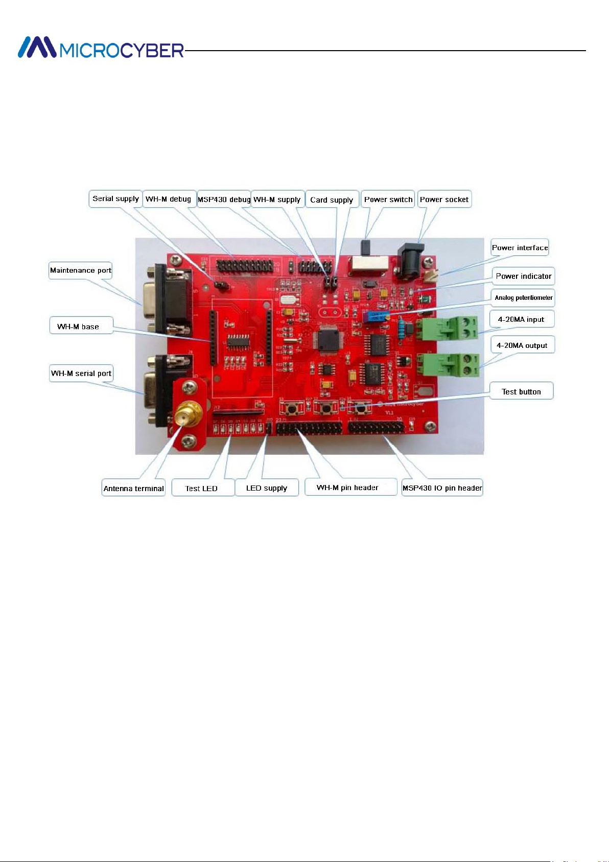
Figure 3.1 Photo of WH-M development board
2
Page 5
http://www.microcyber.cn
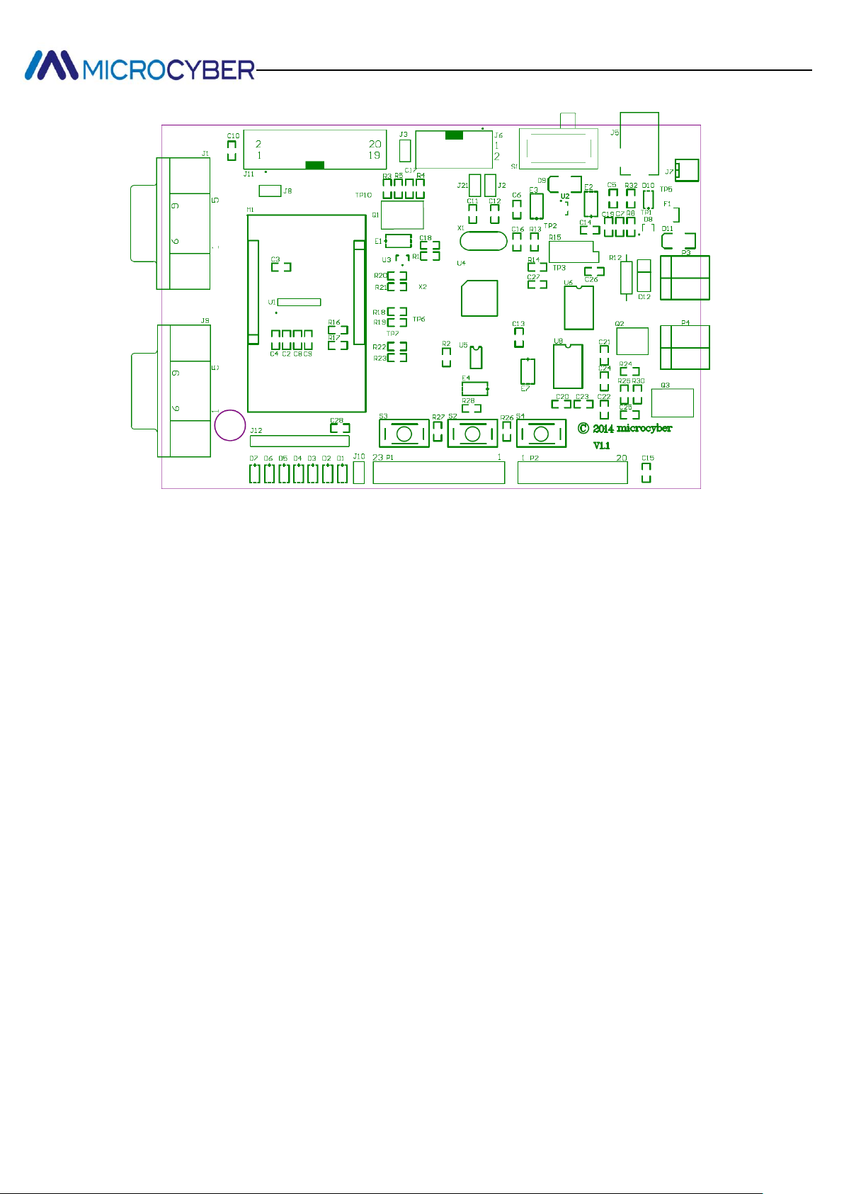
Figure 3.2 WH-M circuit board components layout
Serial supply: Jumper J8, connecting with a jumper wire, mainly control power supply
of the serial module, and easy for low-power evaluation of WH-M.
WH-M debug: JTAG debug port of WH-M master controller. Don’t need to concerned
about it for the user without secondary development.
MSP430 debug port, i.e., instrument board function debug interface of development
board, easy for user to develop instrument board functions through the development
board, evaluate and test those functions at the beginning of the hardware design, to
speed up the development progress.
WH-M supply: Jumper J21, WH-M power supply terminal, can individually provide
power supply to WH-M module, easy for user to check power consumption status of
the instrument board.
Instrument Board supply: Jumper J2, power supply jumper for instrument board
circuit.
Power switch: Power supply toggle switch of the whole circuit.
Power socket: Standard DC power socket.
3
Page 6

http://www.microcyber.cn
Power interface: Additional power plug can lead to power supply for several devices.
Power indicator: Power indicating light of the development board.
Analog potentiometer: Visual display on web of data changes collected can be
provided by adjusting the potentiometer.
4-20MA input: 4-20MA external input terminal.
4-20MA output: 4-20MA output terminal, external power supply required.
Test button: Button interface, easy for user to press when evaluating.
MSP430 IO pin header: Easy for user to connect external device.
WH-M pin header: Pin out all the interfaces of the WH-M module, easy for user to
evaluate the module.
LED supply: Designed for low-power evaluation and can be individually cut off.
Test LED: Respectively connect WH-M’s IO and MSP430’s IO, easy for information
output during debugging.
Antenna terminal: Connect omnidirectional rod antenna.
WH-M serial port: Used for maintenance and to print some relevant information.
Users don’t have to care about.
WH-M base: Socket of WH-M WirelessHART module.
Maintenance port: For PC’s configuration to WH-M.
3.2 Circuit Description
The core controller of instrument board is MSP430F149. The functions of circuits users
will need are shown as follows.
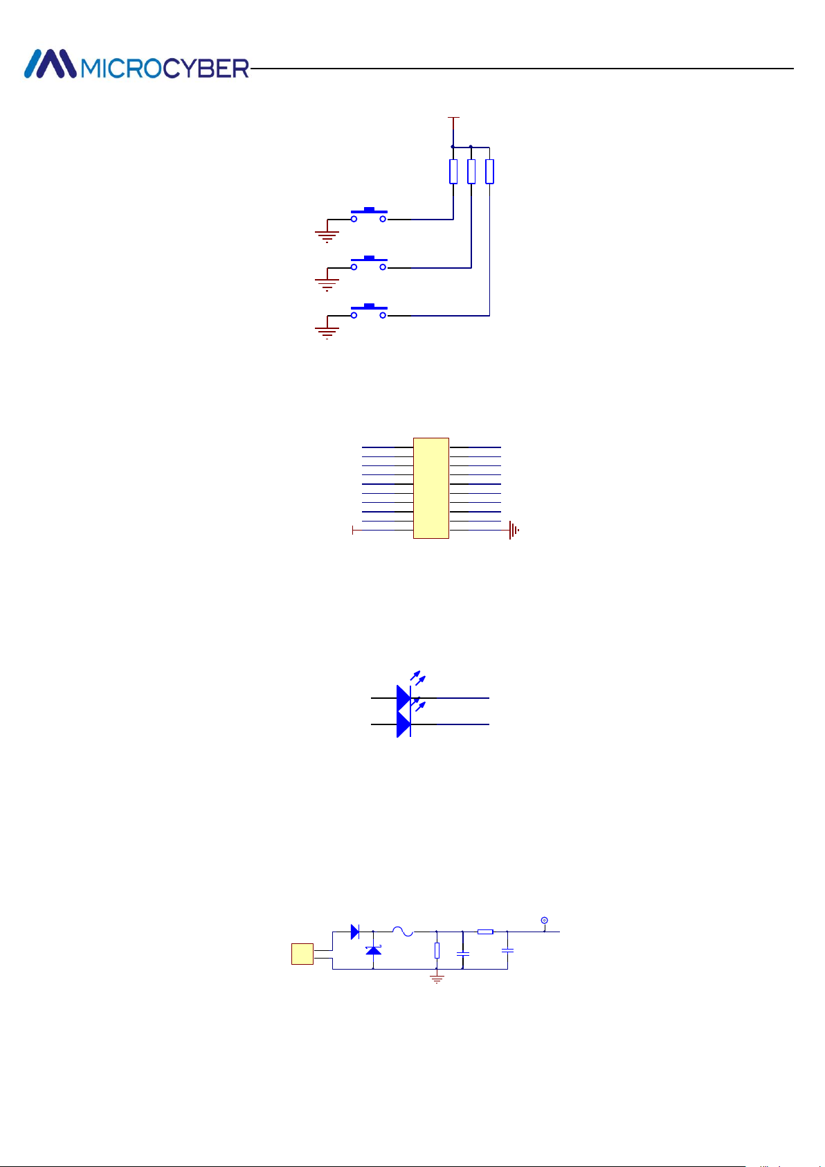
Button circuit shows that the 3 buttons of the development board respectively connect pin
P1.0, P1.1 and P1.4 of MSP430F149. The user can modify function definition of each
button on the basis of own needs.
4
Page 7
http://www.microcyber.cn
112
2
S2
112
2
S3
R26
10K
R27
10K
V3.3
112
2
S4
R28
10K
P10_430
P11_430
P14_430
P30P31
P32_430P33_430
P55_430
P56_430
ADC4 ADC5
ADC6 ADC7
P26_430P27_430
V3.3
P50_430P51_430
P52_430
P54_430
P53_430
P57_430
1 2
3 4
5 6
7 8
9 10
11 12
13 14
15 16
17 18
19 20
P2
Header 10X2
D3
D2 P21_430
P15_430
R12
100R
GND
F1
Fuse 2
TP1
ADC2
4-20mA输入电路
1
2
P3
Header 2
C19
1nF
R8
2K
C7
0.01uF
D11
SS16
D12
SMBJ36CA
4-20mA input circuit
Figure 3.3 Schematic diagram of button pin definition
In the schematic diagram, P2 is partial pin header of MSP430. Figure 3.4 shows its pin
definition. The user can modify them according to actual situation.
Figure 3.4 Definition of MSP430 IO pin header
Two external LEDs are connected to MSP430F149, easy for debugging information
output, speed up the debug progress. Figure 3.5 shows MSP430 pins to LED. LED is on
by low level. 1 k Ω current-limiting resistor is added to LED anode.
Figure 3.5 MSP430 pins to LED
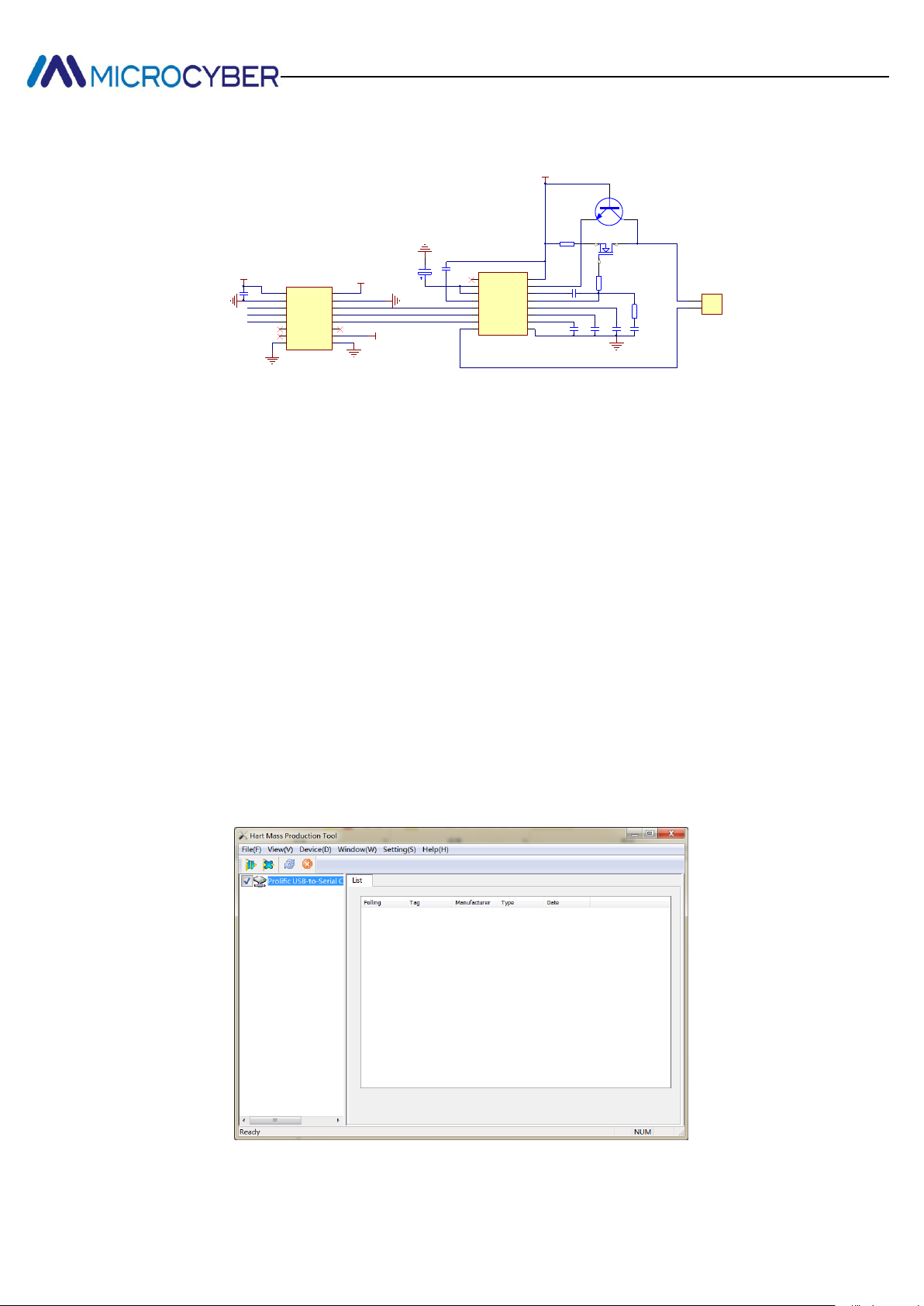
4-20mA input circuits, provided by the development board, enable user to quickly evaluate
the existing 4-20mA device, as shown in Figure 3.6. Through MSP430’s built-in ADC
channel 2, the user can collect data of the 4-20mA device directly by circuits, then
converted into digital signal and transmitted by wireless.
Figure 3.6 4-20mA input circuits
5
Page 8
http://www.microcyber.cn
Q3
REFO1
1
REFO2
2
REFI
3
LV
4
LATCH
5
CLOCK
6
DATA
7
LOOPR8COM
9
C3
10
C2
11
C1
12
DRIVE
13
COMP
14
BOOST
15
VCC
16
U8
AD421
V421
C22
0.15uF
C24
0.01uF
C23
0.47uF
AGND
AGND
E7
4.7u/16V
C20
0.01uF
C21
0.01uF
R30
1K
C25
1000pF
R25
10K
R24
100R
LOOP-
LOOP+
LATCH
CLOCK
DAT421
Q2
4-20mA输出电路
1
2
P4
Header 2
VDD1
1
GND1
2
VIA
3
VIB
4
VIC
5
NC
6
NC
7
GND18GND2
9
VE2
10
NC
11
VOC
12
VOB
13
VOA
14
GND2
15
VDD2
16
U6
ADUM1300
V421
AGND
V421
AGND
V3.3
C27
0.1uF
4-20mA output circuit
The development board also has 4-20mA output circuits with isolation, easy for circuit
output requirements from the user, shown in Figure 3.7:
Figure 3.7 4-20mA output circuits
The user can find the relative driver files in routines for 4-20mA collection and output
circuits mentioned above, and can be modified by the user.
4. WH-M Configuration and Read
By WirelessHART configuration tool, the user shall send commands through maintenance
port to configure WH-M and read configuration information. The configuration tool’s
functions include read/write WH-M’s basic information, network information configuration,
Burst configuration, network monitoring, etc. Refer to below for detail usage methods.
4.1 Connected Device
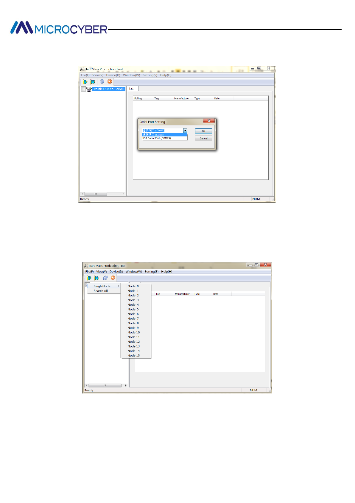
Open WirelessHART configuration tool, see Figure 4.1.
Figure 4.1 Main interface of WirelessHART configuration tool
6
Page 9
http://www.microcyber.cn
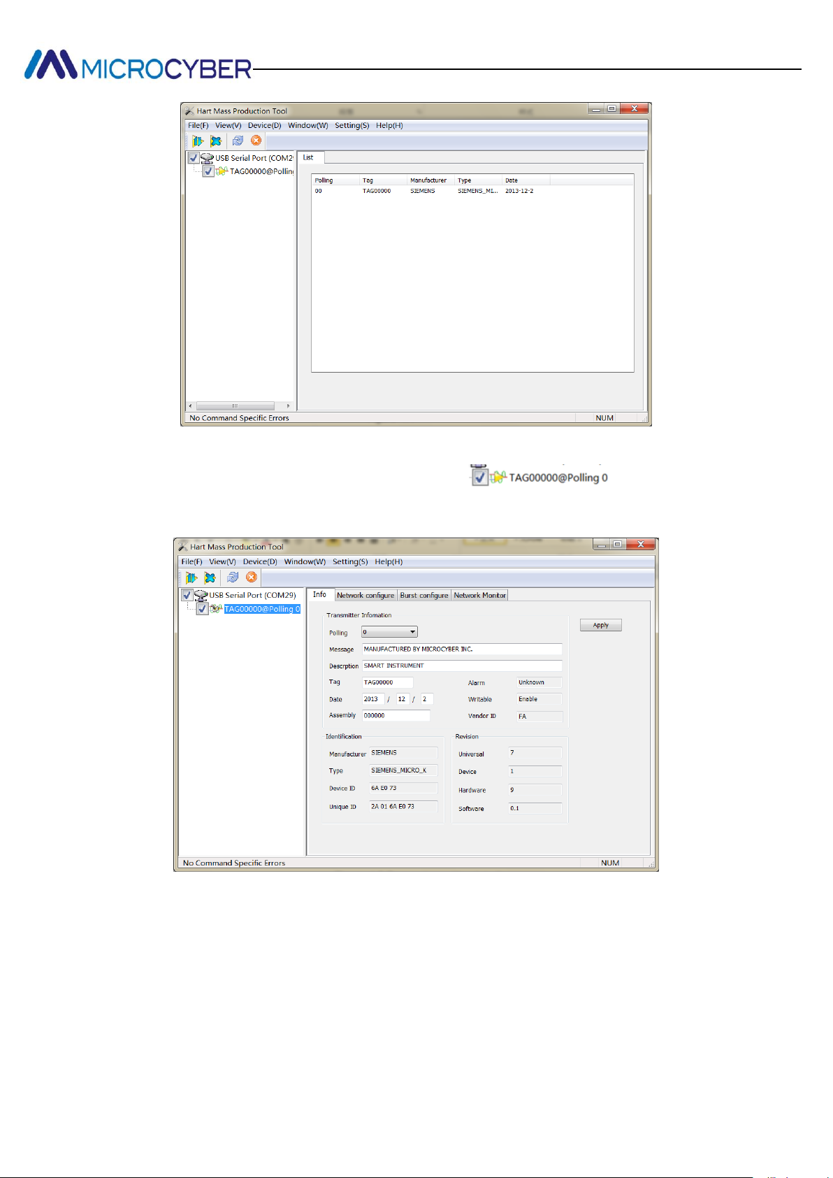
Select an available serial port, select ”Setting(S)-Serial port(S)”, the popup window as
shown in Figure 4.2.
Figure 4.2
After selecting a serial port, its name and serial No. are showed on the left side of the
window, right-click the serial port, as shown in Figure 4.3.
Figure 4.3
Select "SingleNode" or "Search All", the configuration tool begins to search device. When
the device is found, the device label is shown on the left side of the window, and device
list is shown on the right side of the window, including device label, manufacturer, device
type, production date, etc. as shown in Figure 4.4.
7
Page 10
http://www.microcyber.cn
Figure 4.4
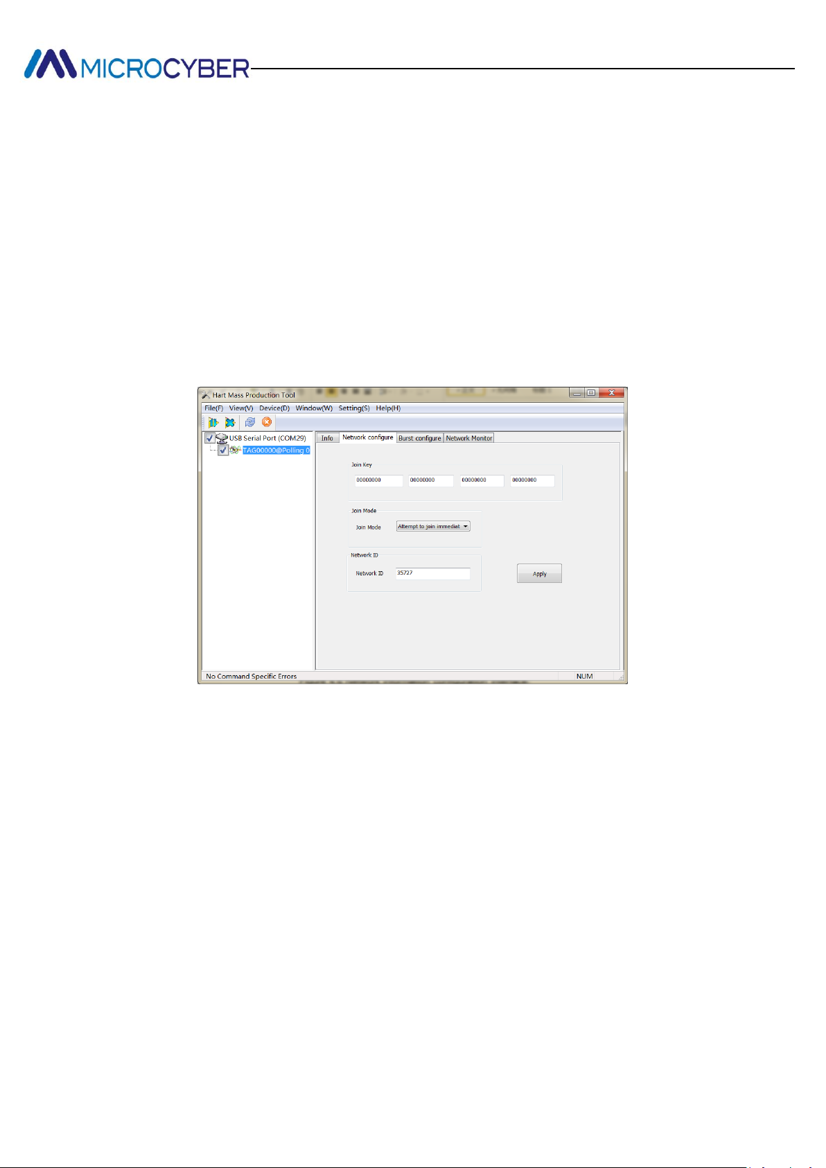
Click the device label on the left side of the window , as shown in
Figure 4.5, WH-M’s parameters are listed for read and write.
Figure 4.5 Parameter setting interface
4.2. Parameter Setting
4.2.1 Basic Information
In Figure 4.5, click "Info" on the right side of the window, the configuration tool will
8
Page 11
http://www.microcyber.cn
transmit basic information reading command to WH-M via a serial port. If the WH-M
responses correctly, the related information will be displayed on the configuration tool
interface, as shown in Figure 4.5. These are factory default parameters, not be modified at
best.
4.2.2 Network Information Configuration
Click “Network configure” on the right side of the window in Figure 4.5, the configuration
tool will transmit module network configuration reading command to WH-M via a serial
port, If the WH-M response correctly, the related information will be displayed on the
configuration tool interface, as shown in Figure 4.6.
Figure 4.6 Network information configuration interface
“Join Key”: Hexadecimal number of 16 bytes, used to start security keys to join network.
“Join Mode”: “Don’t attempt to join.”
“Join now”, if WH-M isn’t in the network, to set this, WH-M will be ready for
join at once.
“Attempt to join immediately on Powerup or reset”
“Network ID”: Decimal number, value range is 0~65535
Note: The above three parameters of the WH-M must be configured before it joins
network, add keys and network ID values must be consistent with the gateway that is
ready to join.
4.2.3 Burst Configuration
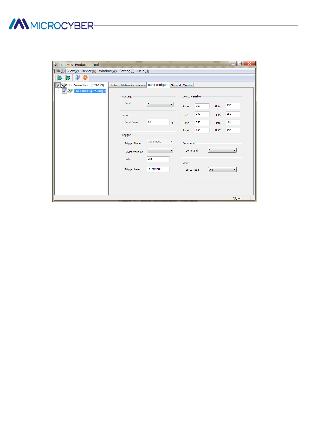
Click “Burst configure” on the right side of Figure 4.5 window, the configuration tool will
transmit module Burst configuration reading command to WH-M via a serial port, If the
9
Page 12
http://www.microcyber.cn
WH-M responses correctly, the related information will be displayed on the configuration
tool interface, as shown in Figure 4.7.
Figure 4.7 Burst configuration interface
“Burst Message”: Value range is 0~4. WH-M supports four Burst messages at most.
Note: When a different Burst message is selected from the drop-down menu, the
corresponding parameter information will be displayed on the interface.
“Period”: Value range is 1, 2, 4, 8, 16, 32, 60~3600s.
“Trigger”: At present only support Continuous trigger mode, and not support device
variables, unit and trigger benchmark.
“Command”: Burst message supports the response of 1, 2, 3, 9, 33 and 48.
“Burst Mode”: Used to start or stop Burst mode.
“Device Variable”: Codes of device variables, specific values and meaning are as below.
243 Battery life (floating point number, unit: day)
244 Percent range
245 Loop current
246 Master variable
247 The second variable
248 The third Variable
249 The fourth variable
250 Not available
This parameter is only associated with Burst command 9 and 33, refer to description
10
Page 13
http://www.microcyber.cn
command 9 and 33 in HART protocol. “250” is set for unavailable device variable. When
Burst command is not command 9 and 33, device variables can be set to “250”
4.2.4 Network Monitoring
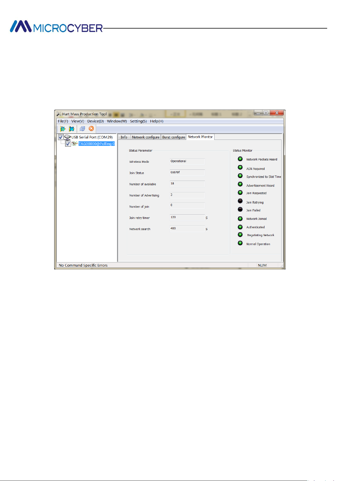
Click "Network Monitor", enter the interface as shown in Figure 4.8.
Figure 4.8 Network monitoring interface
“Status Parameter”: Display network information of the WH-M. See details in Figure 4.8
“Status Monitor”: If green light is on, it shows WH-M passes some steps to join the
network.
After entering the interface, the configuration tool periodically transmit network information
read commands to WH-M, then network monitoring interface will do real-time update.
11
 Loading...