

Page 1

Systemhaus fr Automatisierung
µCAN.8.dio-BOX
Manual Digital I/O-Module
Version 2.00
MicroControl GmbH & Co. KG
Junkersring 23
D-53844 Troisdorf
Fon: 02241 / 25 65 9 - 0
Fax: 02241 / 25 65 9 - 11
http://www.microcontrol.net
Page 2

Table of contents
μCAN.8.dio-BOX 2
1. Safety Regulations . . . . . . . . . . . . . . . . . . . . . . . . . . . . . 6
1.1 General Safety Regulations . . . . . . . . . . . . . . . . . 6
2. Operation of μCAN.8.dio-BOX . . . . . . . . . . . . . . . . . . . 8
2.1 Overview . . . . . . . . . . . . . . . . . . . . . . . . . . . . . . 8
3. Project Planning . . . . . . . . . . . . . . . . . . . . . . . . . . . . . 10
3.1 Module Layout. . . . . . . . . . . . . . . . . . . . . . . . . 10
3.2 Operation Area. . . . . . . . . . . . . . . . . . . . . . . . . 11
3.3 Maximum System Layout. . . . . . . . . . . . . . . . . 12
3.4 Case Dimensions . . . . . . . . . . . . . . . . . . . . . . . 14
4. Assembly and Disassembly . . . . . . . . . . . . . . . . . . . . . 16
4.1 Safety Regulations . . . . . . . . . . . . . . . . . . . . . . 16
4.2 General Information . . . . . . . . . . . . . . . . . . . . . 17
4.3 Assembly . . . . . . . . . . . . . . . . . . . . . . . . . . . . . 18
4.4 Disassembly . . . . . . . . . . . . . . . . . . . . . . . . . . . 19
5. Installation . . . . . . . . . . . . . . . . . . . . . . . . . . . . . . . . . . 20
5.1 Potential Basics. . . . . . . . . . . . . . . . . . . . . . . . . 20
5.2 EMC Considerations. . . . . . . . . . . . . . . . . . . . . 21
5.2.1 Grounding . . . . . . . . . . . . . . . . . . . . . . . . . 22
5.2.2 Shielding of cables . . . . . . . . . . . . . . . . . . . 22
5.2.3 CAN Cable . . . . . . . . . . . . . . . . . . . . . . . . . 23
5.3 Power Supply . . . . . . . . . . . . . . . . . . . . . . . . . . 24
5.4 CAN Bus. . . . . . . . . . . . . . . . . . . . . . . . . . . . . . 26
5.5 Address Selection . . . . . . . . . . . . . . . . . . . . . . . 27
5.6 Baudrate . . . . . . . . . . . . . . . . . . . . . . . . . . . . . 28
5.7 Termination . . . . . . . . . . . . . . . . . . . . . . . . . . . 29
6. Digital Signals . . . . . . . . . . . . . . . . . . . . . . . . . . . . . . . 30
6.1 Function principle / High Side Version . . . . . . . 30
6.2 Function principle / Low Side Version. . . . . . . . 31
6.3 Pinning . . . . . . . . . . . . . . . . . . . . . . . . . . . . . . 33
7. Diagnosis . . . . . . . . . . . . . . . . . . . . . . . . . . . . . . . . . . . 34
7.1 Network Status. . . . . . . . . . . . . . . . . . . . . . . . . 35
7.1.1 Signalling of CAN controller status . . . . . . . 35
Page 3

Table of contents
3 μCAN.8.dio-BOX
7.1.2 Signalling of Network and CAN status . . . . . 36
7.2 Module Status . . . . . . . . . . . . . . . . . . . . . . . . . . 36
7.3 Signal Status . . . . . . . . . . . . . . . . . . . . . . . . . . . 37
7.3.1 High Side Version . . . . . . . . . . . . . . . . . . . . . 37
7.3.2 Low Side Version . . . . . . . . . . . . . . . . . . . . . 37
8. CANopen Protocol . . . . . . . . . . . . . . . . . . . . . . . . . . . . 38
8.1 Introduction . . . . . . . . . . . . . . . . . . . . . . . . . . . 39
8.2 Network Management . . . . . . . . . . . . . . . . . . . 40
8.3 SDO Communication . . . . . . . . . . . . . . . . . . . . 42
8.3.1 SDO Abort Protocol . . . . . . . . . . . . . . . . . . . 43
8.4 Object Dictionary . . . . . . . . . . . . . . . . . . . . . . . 44
8.4.1 Communication Profile. . . . . . . . . . . . . . . . . 45
8.4.2 Device Profile . . . . . . . . . . . . . . . . . . . . . . . . 52
8.4.3 Manufacturer Specific Objects . . . . . . . . . . . 56
8.5 Heartbeat Protocol . . . . . . . . . . . . . . . . . . . . . . 57
8.6 PDO Communication . . . . . . . . . . . . . . . . . . . . 59
8.6.1 Transmission Modes . . . . . . . . . . . . . . . . . . . 60
8.6.2 Receive-PDO . . . . . . . . . . . . . . . . . . . . . . . . 61
8.6.3 Transmit PDO. . . . . . . . . . . . . . . . . . . . . . . . 63
8.6.4 Synchronisation Message . . . . . . . . . . . . . . . 65
8.7 Emergency Message . . . . . . . . . . . . . . . . . . . . . 66
9. Technical Data . . . . . . . . . . . . . . . . . . . . . . . . . . . . . . . 68
Page 4

μCAN.8.dio-BOX MicroControl Version 2.00 Page 4
1
Remarks on CE-conformance of μCAN-modules
μCAN-modules which have CE-conformance label, have passed
test specifications of EU-criteria 89/336/EWG "Electromagnetic
Emission and Immunitiy" and standardized European norms
(EN).
Papers of declaration for EU-conformance, according to Art.10 of
EN, are available at:
MicroControl GmbH & Co. KG
Junkersring 23
D-53844 Troisdorf
Germany
MicroControl reserves the right to modify this manual and/or
product described herein without further notice. Nothing in this
manual, nor in any of the data sheets and other supporting documentation, shall be interpreted as conveying an express or implied warranty, representation, or guarantee regarding the
suitability of the products for any particular purpose. MicroControl does not assume any liability or obligation for damages, actual or otherwise of any kind arising out of the application, use of
the products or manuals.
The products described in this manual are not designed, intended, or authorized for use as components in systems intended to
support or sustain life, or any other application in which failure of
the product could create a situation where personal injury or
death may occur.
© 2016 MicroControl GmbH & Co. KG, Troisdorf
No part of this documentation may be copied, transmitted or
stored in a retrieval system or reproduced in any way including,
but not limited to, photography, magnetic or other recording
means, without prior written permission from MicroControl
GmbH & Co. KG.
Page 5

Page
5 MicroControl Version 2.00 μCAN.8.dio-BOX
1
Page 6

General Safety Regulations Safety Regulations
μCAN.8.dio-BOX
MicroControl Version 2.00 Page 6
1
1. Safety Regulations
Symbol Explanation
Attention !
This symbol marks a paragraph which explains possible danger.
This danger might cause a damage to the system / plant or damage to personnel.
Note
This symbol marks a paragraph which contains useful information for the work with the device or which gives just a hint.
1.1 General Safety Regulations
Attention !
Please read the following chapter in any case, because it contains important information about the secure handling of
electrical devices.
This paragraph gives important information about the conditions
of use. It was written for personnel which is qualified and trained
on electrical devices.
Qualified and trained personnel are persons who fulfil at least
one of the following conditions:
You know the safety regulations for automated machines and
you are familiar with the machine.
You are the operator for the machine and you have been trai-
ned on operation modes. You are familiar with the operation
of devices described in this manual.
You are responsible for setting into operation or service and
you are trained on repairing automated machines. In addition you are trained in setting electrical devices into operation,
to connect the earthing conductor and to label these devices.
Terms of use The devices described in this manual can only be used for the
mentioned applications. Other devices used in conjunction have
to meet the safety regulations and EMI requirements.
Page 7

Safety Regulations General Safety Regulations
Page
7 MicroControl Version 2.00 μCAN.8.dio-BOX
1
To
Attention !
ensure a trouble free and safe operation of the device please
take care of proper transport, appropriate storage, proper assembly as well as careful operation and maintenance.
Hints for Installati-onPlease take care to observe the actual local safety regulations.
If devices are used in a fixed machine without a mains switch for
all phases or fuses, this equipment has to be installed. The fixed
machine must be connected to safety earth.
If devices are supplied by mains please take care that the selected input voltage fits to the local mains.
Safety Notice If devices are supplied by 24V DC, this voltage has to be isolated
from other voltages.
The cables for power supply, signal lines and sensor lines must
be installed in a way that the device function is not influenced by
EMI.
Devices or machines for industrial automation must be constructed in a manner that an unintentional operation is impossible.
By means of hardware and software safety precautions have to
be taken
Attention !
in order to avoid undefined operation of a automated
machine in case of a cable fraction.
If automated machines can cause damage of material or personnel in case of a malfunction the system designer has to take care
for safety precautions. Possible safety precautions might be a
limit switch o
r locking.
Page 8
Overview Operation of μCAN.8.dio-BOX
μCAN.8.dio-BOX
MicroControl Version 2.00 Page 8
2
2. Operation of μCAN.8.dio-BOX
2.1 Overview
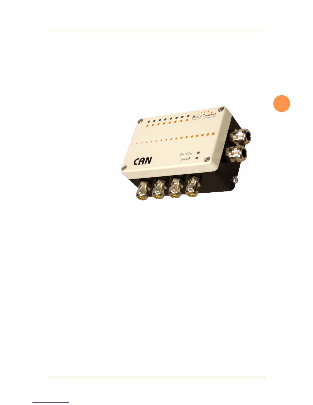
The μCAN.8.dio-BOX is the right solution for digital I/O-signals
via CAN.
Fig. 1: Digital I/O-Module μCAN.8.dio-BOX
The development in automation towards decentralized „intelligent“ systems makes the communication between these components quite important.
Modern automated systems require the possibility to integrate
components from different manufacturers. The solution for this
problem is a common bus system.
All these requirements are fulfilled by the μCAN.8.dio-BOX module. The μCAN.8.dio-BOX runs on the standard fieldbus CAN.
Typical applications for the μCAN.8.dio-BOX are industrial automation, transportation, food industry and environmental technology.
Page 9

Operation of μCAN.8.dio-BOX Overview
Seite
9 MicroControl Version 2.00 μCAN.8.dio-BOX
2
The μCAN.8.dio-BOX runs with the protocol
according to the device profile CiA 401. Other protocol stacks are
available on request.
space saving and
compact
The μCAN.8.dio-BOX is designed for heavy duty applications.
The aluminium cast ensures protection class IP65. The compact,
space saving case gives the freedom to mount the module in
many places.
inexpensive and
service friendly
The quick and easy integration of the μCAN.8.dio-BOX in your
application reduces the development effort. Costs for material
and personnel are reduced. The easy installation makes maintenance and replacement quite simple.
Page 10
Module Layout Project Planning
μCAN.8.dio-BOX
MicroControl Version 2.00 Page 10
3
3. Project Planning
The chapter Project Planning contains information which are important for the system engineer when using the μCAN.8.dioBOX. These information include case dimensions and conditions
of use.
3.1 Module Layout
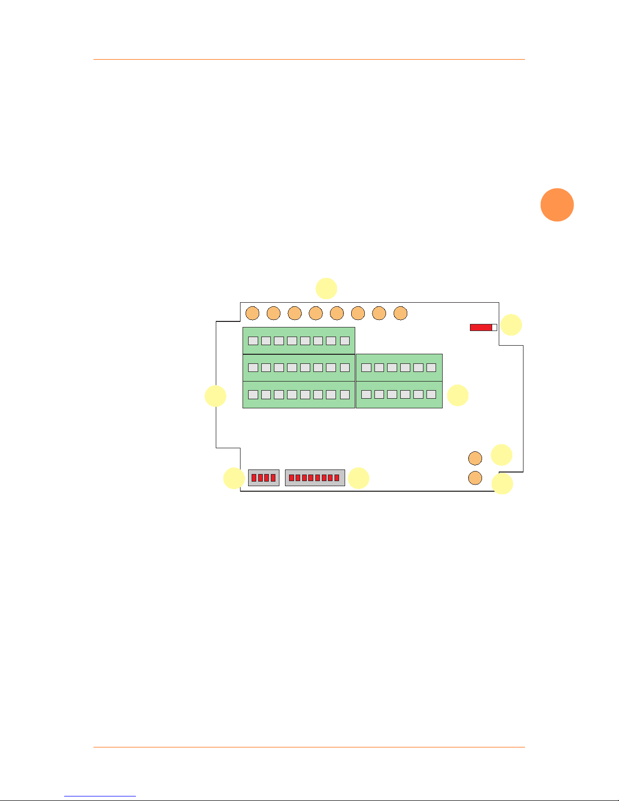
The following figure shows the top view of the μCAN.8.dio-BOX
PCB. Use the figure to identify the terminal blocks, LED’s and DIPswitches.
1: Baudrate switch
2: Module address / ID
3: Bi-color LED for module status
4: Bi-color LED for network status
5: Terminal block for Power / CAN
6: Switch for CANbus termination
7: Bi-color LED for signal status
8: Terminal block for digital signals
Modul IDBaud
Term
Off/On
CAN_H
CAN_L
GND
V+
V-PWR
V+PWR
I/O_1
I/O_2
I/O_3
I/O_4
I/O_5
I/O_6
I/O_7
I/O_8
NS
MS
1
2
4
3
6
5
7
8
Abb. 2: Top view of the μCAN.8.dio-BOX PCB
Page 11

Project Planning Operation Area
Page
11 MicroControl Version 2.00 μCAN.8.dio-BOX
3
3.2 Operation Area
The μCAN.8.dio-BOX is a robust field module for acquisition and
manipulation of digital signals via the CANbus. Every module can
handle up to 8 digital I/O-signals. The port direction of each terminal (input / output) is configured via software. It is not required to setup DIP-switches or jumpers for a configuration change.
The module has a power supply range of 8V - 60V DC.
The PCB is incorporated in a robust case of protection class IP65.
The μCAN.8.dio-BOX is suited for mounting outside the switch
cabinet. Long wires for actors or sensors are not longer necessary.
Influence of EMI is reduced.
The μCAN.8.dio-BOX needs four wires for connection to the power supply and CAN bus. Special CAN bus cables are available as
accessories (refer to Ordering Information).
Page 12

Maximum System Layout Project Planning
μCAN.8.dio-BOX
MicroControl Version 2.00 Page 12
3
3.3 Maximum System Layout
For an operational system at least one network manager (or supervisor system) must be connected to the bus. This network manager might be a PLC or PC equipped with a CAN card. Every
μCAN.8.dio-BOX module is an active node.
A CANopen network manager can handle up to 127 network slaves (refer to Fig. 3, “Maximum System Layout”). Every module
gets a unique address, which is set up via a DIP switch. The CANbus bus is connected through the μCAN modules. The last module in the network must be terminated by a termination switch
(refer to “Termination” on page 29).
ID 1
NetworkManager
ID 2 ID 127
Abb. 3: Maximum System Layout
Page 13

Project Planning Maximum System Layout
Page
13 MicroControl Version 2.00 μCAN.8.dio-BOX
3
The maximum cable length depends on the selected baudrate.
The following table shows the maximum cable length recommended by the CAN in Automation (http://www.can-cia.org).
These distances can be realized with the μCAN.8.dio-BOX.
Tabelle 1: Dependence of baudrate from cable length
Baudrate in kBit/s Cable length in m
1000 25
800 50
500 100
250 250
125 500
100 650
50 1000
20 2500
10 5000
It is
Note
recommended by the CAN in Automation not to use the
baudrate 100 kBit/s in new CANopen systems.
Page 14
Case Dimensions Project Planning
μCAN.8.dio-BOX
MicroControl Version 2.00 Page 14
3
3.4 Case Dimensions
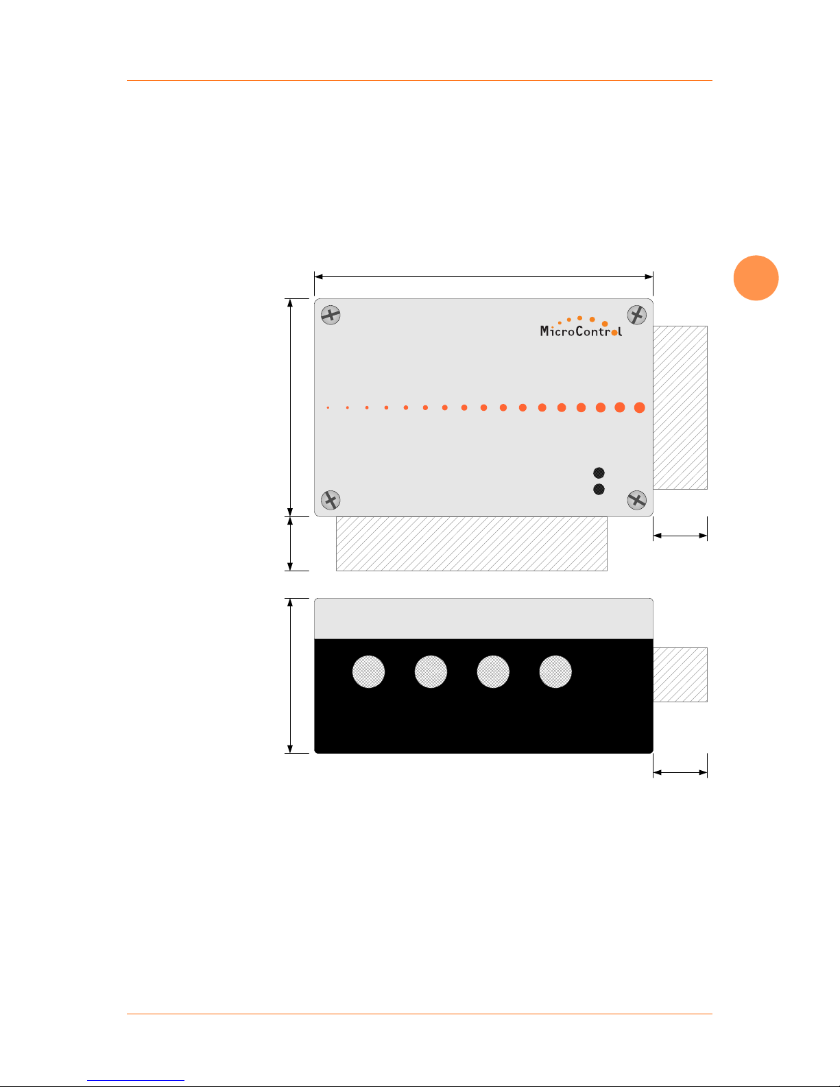
The case dimensions of the module are given in the drawing below. The high protection class IP65 of the module allows an assembly at places with a harsh environment. It is possible to
mount the module inside a switching cabinet as well as direct on
a machine. Please check the technical data section for detailled
information about maximum environment conditions.
125mm
80mm57mm
ON / CAN
ERROR
CAN
Systemhaus für Automatisierung
20mm
20mm
20mm
Abb. 4: Case dimensions
Page 15

Project Planning Case Dimensions
Page
15 MicroControl Version 2.00 μCAN.8.dio-BOX
3
Page 16

Safety Regulations Assembly and Disassembly
μCAN.8.dio-BOX
MicroControl Version 2.00 Page 16
4
4. Assembly and Disassembly
4.1 Safety Regulations
This paragraph gives important information about the conditions
of
Attention !
use. It was written for personnel which is qualified and trained
on electrical devices.
Qualified and trained personnel are persons who fulfill at least
one of the following conditions:
You know the safety regulations for automated machines and
you are familiar with the machine.
You are the operator for the machine and you have been trai-
ned on operation modes. You are familiar with the operation
of devices described in this manual.
You are responsible for setting into operation or service and
you are trained on repairing automated machines. In addition you are trained in setting electrcal devices into operation,
to connect the earthing conductor and to label these devices.
Terms of Use The devices described in this manual can only be used for the
mentioned applications. Other devices used in conjuction have to
meet the safety regulations and EMI requirements.
To ensure a trouble free and safe operation of the device please
take
Attention !
care of proper transport, appropriate storage, proper assem-
bly as well as careful operation and maintenance.
Page 17
Assembly and Disassembly General Information
Page
17 MicroControl Version 2.00 μCAN.8.dio-BOX
4
4.2 General Information
Assembly The µCAN modules should be assembled on an at least 2 mm
thick mounting plate or direct in the plant. The module is fixed
with 2 screws of type M4, which are plugged into the bottom part
of the case. You find an assembly template in the appendix of this
manual.
Power Supply You need a cable with two conductors for power supply. The ca-
ble is inserted from the right side into the case, where the terminals for power supply are located. However it makes sense to use
a cable with four conductors in order to run the CAN bus over the
same cable.
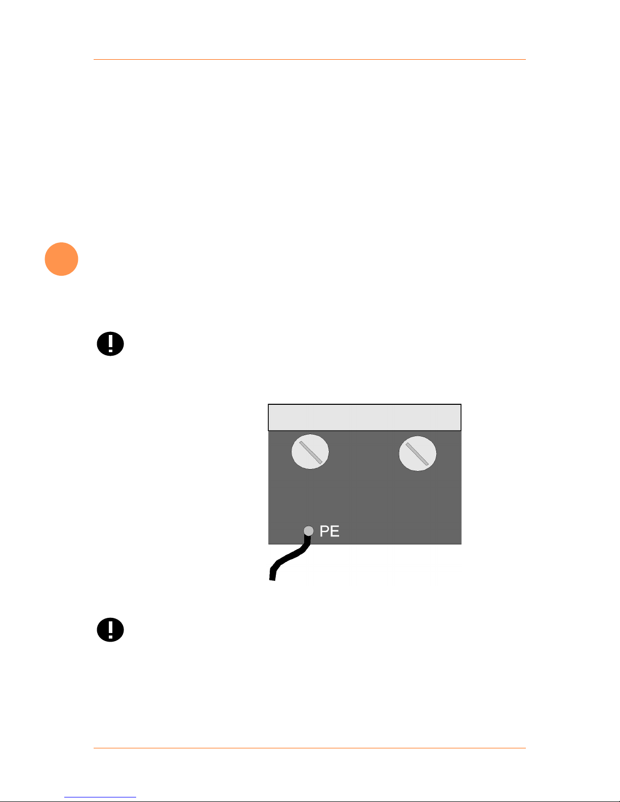
Earthed Conductor The non-fused earthed conductor is connected at the terminal
outside the case (refer to Fig. 5, “Connection of earthed conductor”). The non-fused earthed conductor may not lead inside the
case because of EMI.
The
Attention !
non-fused earthed conductor may not lead inside the µCAN
case and may not be connected to a terminal inside the case.
Abb. 5: Connection of earthed conductor
Attention !
Operation of the µCAN module is only permitted with closed
case.
Page 18

Assembly Assembly and Disassembly
μCAN.8.dio-BOX
MicroControl Version 2.00 Page 18
4
4.3 Assembly
Assembly is performed with help of the template attached to this
manual. With the template all necessary bore-holes for screws of
type M4 can easily be drilled. If the module is directly fixed to the
machine make sure to take the proper drill size for tapping.
When fixing several modules at the same place please make
sure
Note
to leave some area for the PG screws.
For a quick identification of the modules during operation you
may use paper sticker. Please write down the ID that is set for the
module.
Please make sure that the first node and the last node in the CAN
network
Note
is terminated with a resistor (refer to “Termination” on
page 29).
Page 19

Assembly and Disassembly Disassembly
Page
19 MicroControl Version 2.00 μCAN.8.dio-BOX
4
4.4 Disassembly
Please make sure to disconnect the power supply from the device
first!
Open the cover from the module and remove the temperature
sensors first. Now you can remove the cables for CAN bus and
power supply from the terminals.
Unlock the fixing screws and remove the module. For a safe
transport remove the PG screws and close the cover again.
Page 20

Potential Basics Installation
μCAN.8.dio-BOX
MicroControl Version 2.00 Page 20
5
5. Installation
5.1 Potential Basics
The potential environment of a system that is realized with μCAN
modules is characterized by following features:
The CAN bus potential is isolated from the power supply.
The electronic of the μCAN modules is isolated from the po-
wer supply.
All μCAN modules have a separate power supply.
All I/O signals are optically isolated from the CAN bus poten-
tial.
Page 21

Installation EMC Considerations
Page
21 MicroControl Version 2.00 μCAN.8.dio-BOX
5
5.2 EMC Considerations
EMC (Electromagnetic Compatibility) is the ability of a device to
work in a given electromagnetic environment without influencing this environment in a not admissible way.
All μCAN modules fit these requirements and are tested for electromagnetic compatibility in a EMC laboratory. However a EMC
plan should be done for the system in order to exclude potential
noise sources.
Noise signals can couple in different ways. Depending on that
way (guided wave propagation or non-guided wave propagation) and the distance to the noise source the kinds of coupling are
differentiated:
DC Coupling
If two electronic circuits use the same conductor we speak of a
DC coupling. Noise sources are in that case: starting motors, frequency converters (switching devices in general) and different
potentials of cases or of the common power supply.
Inductance Coupling
An inductance coupling is given between two current-carrying
conductors. The current in a conductor will cause a magnetic field
which induces a voltage in the second conductor (transformer
principle). Typical noise sources are transformer, power cables
and RF signal cables.
Capacitive Coupling
A capacitive coupling is given between two conductors which
have a different potential (principle of a capacitor). Noise sources
are in that case: parallel running conductors, static discharge and
contactors.
RF Coupling
A RF coupling is given when electromagnetic fields hit a conductor. This conductor works like an antenna for the electromagnetic
field and couples the noise into the system. Typical noise sources
are spark plugs and electric motors. Also a radio set might be a
noise source.
To reduce the impact of noise sources please take care to follow
the basic EMC rules.
Page 22

EMC Considerations Installation
μCAN.8.dio-BOX
MicroControl Version 2.00 Page 22
5
5.2.1 Grounding
General All inactive metal plates must be grounded with low impedance.
By this step all elements of the system will have the same potential.
Please take care that the ground potential never carries a dangerous voltage. The grounding must be connected to the safety
earth.
Grounding of
μCAN-Modules
The µCAN modules are grounded by the contact which is mounted under one of the PG screws (see fig. 5, “Connection of
earthed conductor”). Additional contacts can be mounted under
the PG screws for shielding purposes on demand. The ground
potential may not be connected to a terminal inside the case.
Grounding of other
modules
If µCAN modules are shipped in a plastic case they have to be
grounded with a metal tape.
5.2.2 Shielding of cables
If noise is coupled to a cable shield it is grounded to safety earth
via the metal cover. The cable shields have to be connected to
the safety earth with low impedance.
Cable Types For installation of the µCAN module you should only use cable
with a shield that covers at least 80% of the core. Do not use cable with a shield made from metallized foil because it can be damaged very easy and has not a good shielding.
Cable Layout In general the cable shield should be grounded on both ends.
The cable shield should only be grounded on one end if an attenuation is necessary in the low frequency range. The cable shield
can not be grounded on both ends for temperature sensors. The
grounding on one end of the cable is necessary if
there is no contact to the safety earth possible,
analogue signals with only a few mV or mA are transmitted
(temperature sensors).
Page 23

Installation EMC Considerations
Page
23 MicroControl Version 2.00 μCAN.8.dio-BOX
5
5.2.3 CAN Cable
The CAN cable must meet the requirements of ISO11898. The
cable must meet the following specifications:
Tabelle 2: Specifications of CAN bus cable
Parameter Value
Impedance 108 - 132 Ohm (nom. 120 Ohm)
Specific Resistance 70 mOhm/Meter
Specific Signal Delay 5 ns/Meter
The CAN bus cable is connected to the µCAN.8.dio-BOX module
via terminals inside the case. For the pinning of the terminal refer
to “CAN Bus” on page 26 of this manual.
Do not confuse the signal lines of the CAN bus, otherwise communication
Attention !
between the modules is impossible. The shield of the
CAN bus cable may never lead inside the µCAN case. Never
connect the shield to one of the terminals inside the case.
Page 24

Power Supply Installation
μCAN.8.dio-BOX
MicroControl Version 2.00 Page 24
5
5.3 Power Supply
The μCAN.8.dio-BOX modules are designed for industrial applications. By means of a DC/DC converter the CANbus of the module is isolated from the supply voltage. The supply voltage must
be within the range from 8 V DC to 60 V DC. The input is protected against confusing the poles.
Please make sure not to confuse the poles when connecting the
power supply. The positive supply is connected to the terminal
V+. The positive supply for the output stage is connected to the
terminal V+PWR.
The negative supply is connected to the terminal GN
D. The negative supply for the output stage is connected to the terminal V-
PWR.
Modul IDBaud
Term
Off/On
CAN_H
CAN_L
GND
V+
V-PWR
V+PWR
I/O_1
I/O_2
I/O_3
I/O_4
I/O_5
I/O_6
I/O_7
I/O_8
NS
MS
1
2
4
3
6
5
7
8
Supply for electronic
Supply for output stage
Abb. 6: Connection of power supply
The output stage can be supplied via a separate power source or
links have to be made between V+ and V+PWR as well as GND
and V-PWR.
The
Attention !
maximum supply voltage for the output drivers is 50V DC.
The maximum supply voltage for the electronic is 60V DC. Higher voltages will destroy the electronic.
Page 25

Installation Power Supply
Page
25 MicroControl Version 2.00 μCAN.8.dio-BOX
5
The terminals GND and V-PWR are not linked internally. The maximum potential difference between these terminals may not exceed 50mV.
You
Note
must always connect the power supply for the output stage,
even if the module is only used in a digital input configuration.
A cable shield may not lead into the housing or may not be connected to a
Attention !
terminal inside the housing. Cable shields have to be
connected to the terminals outside the housing.
Page 26

CAN Bus Installation
μCAN.8.dio-BOX
MicroControl Version 2.00 Page 26
5
5.4 CAN Bus
The two wires of the CAN bus are connected to the appropriate
terminals.
To
Note
reduce the influence of EMI please take care that the CAN bus
cable does not cross the wires of the signal lines.
The CAN bus line with positive potential must be connected to
the terminal CAN_H. The CAN bus line with negative potential
must be connected to the terminal CAN_L.
Modul IDBaud
Term
Off/On
CAN_H
CAN_L
GND
V+
V-PWR
V+PWR
I/O_1
I/O_2
I/O_3
I/O_4
I/O_5
I/O_6
I/O_7
I/O_8
NS
MS
1
2
4
3
6
5
7
8
CAN bus
Abb. 7: Connection of CAN bus
If you confuse the poles the communication on the bus will not
be possible. The
Attention !
shield of the CAN bus may not lead into the housing and may not be connected to a terminal inside the housing.
Cable shields have to be connected to the terminals outside the
housing.
If you use a Sub-D connector with 9 pins (according to CiA standard), the
Note
conductor CAN_H is connected to pin 7 and the con-
ductor CAN_L is connected to pin 2.
Page 27

Installation Address Selection
Page
27 MicroControl Version 2.00 μCAN.8.dio-BOX
5
5.5 Address Selection
Address selection of the μCAN.8.dio-BOX module is done via a
8-pin DIP-switch, marked "Modul-ID" which is located at the bottom of the PCB. Selection of the address may be done with a
small screw driver.
1 2 3 4 5 6 7 8
OFF
Modul ID
Abb. 8: Setup of module address (here address 9 is shown)
The 8-pin DIP-switch sets the binary code for the module
address. The first pin of the switch (marked with ’1’) represents
bit 0 of a byte. The last pin of the switch (marked with ’8’) represents bit 7 of a byte.
Valid module addresses are within the range from 1..127, resp.
01h..7Fh.
Attention !
Each node within a CANopen network must have a
unique module address (Node ID). Two nodes with the same
Node ID are not allowed.
The selected address is read during initialization of the module,
after Power-on or Reset. The module runs with the selected Node
ID until a new Node ID is selected and a Reset is performed (via
the CAN bus) or the power supply is switched off
Switch 8 must always be in OFF position. Do not put all switches
in the
Attention !
OFF position. In these configurations the module will not
start to communicate on the bus.
Page 28

Baudrate Installation
μCAN.8.dio-BOX
MicroControl Version 2.00 Page 28
5
5.6 Baudrate
Baudrate selection of the μCAN.8.dio-BOX module is done via a
4-pin DIP-switch, marked "Baud" which is located at the bottom
of the PCB. Selection of the baudrate may be done with a small
screw driver.
1 2 3 4
OFF
Baud
Abb. 9: Setup of baudrate (here 1 MBit/s is shown)
The 4-pin DIP-switch sets the binary code for the module baudrate. The first pin of the switch (marked with ’1’) represents bit 0 of
a byte. The last pin of the switch (marked with ’4’) represents bit
3 of a byte.
The supported baudrates of the μCAN.8.dio-BOX module are given in the following table. The values are recommended by the
CiA.
Tabelle 3: Setup of baudrate
Baudrate (kBit / s) 1 2 3 4
1000 1 0 0 1
800 0 0 0 1
500 1 1 1 0
250 0 1 1 0
125 1 0 1 0
100 0 0 1 0
50 1 1 0 0
20 0 1 0 0
10 1 0 0 0
Page 29

Installation Termination
Page
29 MicroControl Version 2.00 μCAN.8.dio-BOX
5
5.7 Termination
The modules at both ends in the CAN network have to be terminated with a resistor of 120 ohms. That means the modules at
the end of the bus line are not reflecting back power and the
communication can not be disturbed.
For termination of the μCAN.8.dio-BOX the "Term" switch must
be turned from position "Term Off“ to position "Term On“.
Modul IDBaud
Term
Off/On
CAN_H
CAN_L
GND
V+
V-PWR
V+PWR
I/O_1
I/O_2
I/O_3
I/O_4
I/O_5
I/O_6
I/O_7
I/O_8
NS
MS
1
2
4
3
6
5
7
8
Termination off
Abb. 10: Termination of CANbus
Please make sure that only the devices at both ends of a CAN bus
Attention !
are terminated.
Page 30

Function principle / High Side Version Digital Signals
μCAN.8.dio-BOX
MicroControl Version 2.00 Page 30
6
6. Digital Signals
The μCAN.8.dio-BOX has eight digital I/O terminals. The terminal blocks are labeled with "I/O_1" to "I/O_8" from left to right
on the PCB.
Please keep the basics of EMI rules in mind when planning the
wiring. Only proper wiring and EMI precautions make sure that
the module runs without trouble.
6.1 Function principle / High Side Version
Configuration of each terminal (Input or Output) is performed
via CANopen. In "Digital Input" mode the Power-MOSFET is always off. The input voltage at the terminal is compared with a
reference voltage, which is set to V+
PWR / 2 (level is 50% of the
output stage supply voltage).
Logik
V+PWR
R
in
I/O
Abb. 11: Schematic digital I/O terminal / High Side Version
Page 31

Function principle / Low Side Version Digital Signals
μCAN.8.dio-BOX
MicroControl Version 2.00 Page 31
6
In "Digital Output" mode the Power-MOSFET is driven via the
control logic. The logic block detects over current, short current
and thermal overload.
Tabelle 4: Electrical Parameters
Parameter Value
V+PWR 10 .. 50 V
Impedance R
in
24,2 kOhm
I
out
1,4 A maximal
Switching Level 0,5 * V+PWR
6.2 Function principle / Low Side Version
In "Digital Input" mode the Power-MOSFET is always off. The input voltage at the terminal is compared with a reference voltage,
which is set to V+PWR / 2 (level is 50% of the output stage supply voltage).
Logik
R
in
I/O
Abb. 12: Schematic digital I/O terminal / Low Side Version
Page 32

Function principle / Low Side Version Digital Signals
μCAN.8.dio-BOX
MicroControl Version 2.00 Page 32
6
In "Digital Output" mode the Power-MOSFET is driven via the
control logic.
Attention !
In the Low Side Version there is no monitoring of over current
and short circuit. Also there is no signalling by LED or EMCY-messages ( please refer to “Emergency Message” on page 66 ).
Although the digital outputs are protected against overload conditions by means of thermal protection of the drivers. In constant
overlaod condition the driver will switch On and Off the load so
that there will be a PWM. If still remaining the overload condition
at last the driver will be completely switched off - until thermal
conditions are inside the driver´s specification again.
Tabelle 5: Electrical Parameters
Parameter Value
V+PWR 10 .. 50 V
Impedance R
in
33,3 kOhm
I
out
2 A maximum
Switching Level 0,5 * V+PWR
Page 33

Pinning Digital Signals
μCAN.8.dio-BOX
MicroControl Version 2.00 Page 33
6
6.3 Pinning
The terminal block of the μCAN.8.dio-BOX is designed to
connect digital sensors with 3 wires. The sensor gets the positive
supply voltage (V+PWR) from terminal row B. The ground potential is located in terminal row C (V-PWR).
The binary control lines are connected to row A. The state of each
line is displayed by means of bi-color LEDs.
Modul IDBaud
Term
Off/On
CAN_H
CAN_L
GND
V+
V-PWR
V+PWR
I/O_1
I/O_2
I/O_3
I/O_4
I/O_5
I/O_6
I/O_7
I/O_8
NS
MS
A
B
C
Abb. 13: Terminals for signal lines
All
Attention !
signal lines may only be connected in power off state in order
to prevent a damage of the electronic.
Page 34

Diagnosis
μCAN.8.dio-BOX
MicroControl Version 2.00 Page 34
7
7. Diagnosis
All modules of the μCAN family have LEDs to display the operating state and to signalize an error state. The light of the LEDs can
be seen through beam waveguides on top of the housing.
The μCAN.8.dio-BOX has two Duo-LEDs (green/red) labeled
with "NS" (Network Status) and "MS" (Module Status) on the
PCB.
On the case cover the LEDs are marked as ON/CAN for the network
Note
status and ERROR for the module status.
The state of the digital I/O terminals is displayed by eight bi-color
LEDs (position 7 in the figure below).
Modul IDBaud
Term
Off/On
CAN_H
CAN_L
GND
V+
V-PWR
V+PWR
I/O_1
I/O_2
I/O_3
I/O_4
I/O_5
I/O_6
I/O_7
I/O_8
NS
MS
1
2
4
3
6
5
7
8
Abb. 14: Position of LEDs on the module
In normal operation all LEDs should have a green or orange color.
A
Note
red steady light or a red blinking of a LED indicates an error
condition.
Page 35

Diagnosis Network Status
Page
35 MicroControl Version 2.00 μCAN.8.dio-BOX
7
7.1 Network Status
The LED marked with Network Status" (on the case cover denoted as ON/CAN) displays the status of the communication link.
7.1.1 Signalling of CAN controller status
The red LED is signalling the status of the CAN controler. Only in
fault condition the red LED will show the status.
Initialisation (Autobaud Detection)
NMT Status: Device in "Stopped" state
NMT Status: Device in "Pre-operational" state
NMT Status: Device in "Operational" state
CAN Status: Controller in "Warning" state
CAN Status: Controller in "Error Passive" state
CAN Status: Controller in "Bus-Off" state
Page 36

Module Status Diagnosis
μCAN.8.dio-BOX
MicroControl Version 2.00 Page 36
7
7.1.2 Signalling of Network and CAN status
In combination there will be shown the network status and the
controler status.
7.2 Module Status
The LED marked with Module Status" (on the case cover denoted
as Error) displays the status of the device hardware.
Device in "Pre-operational" state, CAN Controller in "Warning" state
Device in "Operational" state, Controller in "Error Passive" state
Modul Status: Function/Power OK ( No short circuit / overload )
Modulstatus: Wrong setting of Baudrate DIP switches
Modulstatus: Wrong setting of Address DIP switches
Modulstatus: Short circuit / Overload on output ( Not available in LS Version )
Page 37

Diagnosis Signal Status
Page
37 MicroControl Version 2.00 μCAN.8.dio-BOX
7
7.3 Signal Status
The eight LEDs above the terminal block indicate the state of the
digital signal present on each input / output.
7.3.1 High Side Version
Tabelle 6: LED for Signal Status / High Side
Signal LED is To indicate
Green Digital high-signal at terminal ( Input )
Orange Terminal configured as output, output has been
switched on
Red Terminal configured as output, short-circuit on
output driver
7.3.2 Low Side Version
Tabelle 7: LED for Signal Status / Low Side
Signal LED is To indicate
Green Digital high-signal at terminal ( Input )
Orange not applicable
Red Terminal configured as output, output has been
switched on
Page 38

CANopen Protocol
μCAN.8.dio-BOX
MicroControl Version 2.00 Page 38
8
8. CANopen Protocol
This chapter provides detailed information on how to connect
the modules of the μCAN-series to a CANopen-Manager. A CANopen-Manager can be a PLC, a PC with a CAN interface or any
other CAN-Device with NMT functionality.
For more information about CANopen manager please refer to
the supplied manuals of your CANopen master device.
This documentation provides the actual implemented functions
and services of the μCAN.8.dio-BOX.
Page 39

CANopen Protocol Introduction
Page
39 MicroControl Version 2.00 μCAN.8.dio-BOX
8
8.1 Introduction
The identifiers of the μCAN.8.dio-BOX are set up according to
the Pre-defined Connection Set, which is described in the
CANopen communication profile DS-301 in detail. The following
table gives an overview of the supported services.
Tabelle 8: Identifier values according to the Pre-defined Connection Set
Object COB-ID (dec.) COB-ID (hex)
Network Management 0 0x000
SYNC 128 0x080
EMERGENCY 129 - 255 0x081 - 0x0FF
PDO 1 (Transmit) 385 - 511 0x181 - 0x1FF
PDO 1 (Receive) 513 - 639 0x201 - 0x27F
SDO (Transmit) 1409 - 1535 0x581 - 0x5FF
SDO (Receive) 1537 - 1663 0x601 - 0x67F
Heartbeat / Boot-Message 1793 - 1919 0x701 - 0x77F
The direction (Transmit / Receive) has to be seen from the devices point of view.
Page 40

Network Management CANopen Protocol
μCAN.8.dio-BOX
MicroControl Version 2.00 Page 40
8
8.2 Network Management
By means of the Network Management (NMT) messages the
state of a CANopen node can be changed (Stopped / Pre-Operational / Operational).
Start Node
ID DLC B0 B1
0 2 01h Nod
e
Start Node
Node = module address, 0 = all modules
By transmitting the "Start Node" command the CAN-node will be
set into Operational mode. This means that the node can handle
PDO-communication.
Stop Node
ID DLC B0 B1
0 2 02h Nod
e
Stop Node
Node = module address, 0 = all modules
By transmitting the "Stop Node" command the CAN-node will be
set into Stopped mode. This means that the node can not handle
any services except NMT commands.
Pre-Operational
ID DLC B0 B1
0 2 80h Nod
e
Enter Pre-Operational
Node = module address, 0 = all modules
By transmitting the „Enter Pre-Operational“ command the CANnode will be set into Pre-Operational mode. In this state the node
can not handle PDO messages.
Page 41

CANopen Protocol Network Management
Page
41 MicroControl Version 2.00 μCAN.8.dio-BOX
8
Reset Node
ID DLC B0 B1
0 2 81h Nod
e
Reset Node
Node = module address, 0 = all modules
By transmitting the „Reset Node“ command the CAN-node will
issue a reset operation. After reset the node will send a "Boot-up
Message" (refer to “Heartbeat Protocol” on page 57) and enter
the Pre-operational state automatically.
Page 42

SDO Communication CANopen Protocol
μCAN.8.dio-BOX
MicroControl Version 2.00 Page 42
8
8.3 SDO Communication
All parameters of the devices (organized in an object dictionary)
are accessed via the SDO service (Service Data Object). A SDO
message has the following contents:
ID DLC B0 B1 B2 B3 B4 B5 B6 B7
8 CMD Index Sub-
In-
dex
Data
For calculation of the SDO message identifier please refer to “Introduction” on page 39.
The Command Byte (CMD) has the following meaning:
Master wants to read from Slave 40h
Slave answers on the read-request
42h
Master wants to write to Slave 22h
Slave answers on the write-request 60h
The
Note
byte order for the fields "Index" and "Data" is least significant
byte first (Intel format).
The
Attention !
minimum time delay between two succeeding SDO-commands must be greater than 20ms. Faster communication might
lead to an unpredictible device status.
Page 43

CANopen Protocol SDO Communication
Page
43 MicroControl Version 2.00 μCAN.8.dio-BOX
8
8.3.1 SDO Abort Protocol
The SDO abort protocol is used to signalize a fault when accessing an object. This SDO abort protocol has the following format:
ID DLC B0 B1 B2 B3 B4 B5 B6 B7
8 80h Index Sub-
In-
dex
Abort Code
The identifier as well as the index and sub-index correspond to
the SDO request.
The abort code may have the following values:
Tabelle 9: SDO abort codes
Abort code Description
0504 0001h Client / Server command specifier not vali
d / unknown
0601 0000h Unsupported access to an object
0601 0001h Attempt to read a "write-only" object
0601 0002h Attempt to write a "read-only" object
0602 0000h Object does not exist in the object dictionary
0609 0011h Sub-index does not exist
Page 44

Object Dictionary CANopen Protocol
μCAN.8.dio-BOX
MicroControl Version 2.00 Page 44
8
8.4 Object Dictionary
This chapter describes the implemented objects for the digital
module μCAN.8.dio-BOX. For further information please refer to
the CANopen communication profile DS-301 and the device profile DS-401.
Page 45

CANopen Protocol Object Dictionary
Page
45 MicroControl Version 2.00 μCAN.8.dio-BOX
8
8.4.1 Communication Profile
The module μCAN.8.dio-BOX supports the following objects
from the communication profile DS-301:
Tabelle 10: Supported objects of the communication profile
Index Name
1000h Device Profile
1001h Error Register
1003h Predefined Error-Register
1005h COB-ID SYNC-Message
1008h Manufacturer Device Name
1009h Manufacturer Hardware Version
100Ah Manufacturer Software Version
1010h Store Parameters
1011h Restore Default Parameters
1014h COB-ID Emergency-Message
1017h Heartbeat Producer Time
1018h Identity Object
1400h 1
st
Receive PDO Parameter
1600h 1
st
Receive PDO Mapping
1800h 1
st
Transmit PDO Parameters
1A00h 1
st
Transmit PDO Mapping
Page 46

Object Dictionary CANopen Protocol
μCAN.8.dio-BOX
MicroControl Version 2.00 Page 46
8
Device Profile
Index 1000h The object at index 1000h describes the type of device and its
functionality.
Sub-Index Data Type Acc. Name Default Value
0 Unsigned32 ro Device Profile 0003 0191h
The object is read-only. Only sub-index 0 is supported. An access
to other sub-indices will lead to an error message.
Beispiel: read parameter, module ID = 2, index = 1000h
ID DLC B0 B1 B2 B3 B4 B5 B6 B7
602h 8 40h 00h 10h 00h 00h 00h 00h 00h
As response the μCAN.8.dio-BOX will send:
ID DLC B0 B1 B2 B3 B4 B5 B6 B7
582h 8 42 00 01h 00 91h 01h 03h 00
Byte 5 + Byte 6 = 0191h = 401d (Device Profile Number)
Byte 7 + Byte 8 = 0003h = 3 (Additional Information)
Error Register
Index 1001h The object at index 1001h is an error register for the device.
Sub-Index Data Type Acc. Name Default Value
0 Unsigned8 ro Error Register 00h
The object is read-only. Only sub-index 0 is supported. An access
to other sub-indices will lead to an error message.
Beispiel: read parameter, module ID = 2, Index = 1001h
ID DLC B0 B1 B2 B3 B4 B5 B6 B7
602h 8 40h 01h 10h 00 00 00 00 00
Page 47

CANopen Protocol Object Dictionary
Page
47 MicroControl Version 2.00 μCAN.8.dio-BOX
8
As response the module will return its error register value. The following error types are supported:
Generic Error Bit 0 is set to ’1’. The generic error is set due to hardware faults.
Communication
Error
Bit 4 is set to ’1’. The communication error is set due to faults on
the CAN bus.
The object is read-only. Only sub-index 0 is supported. An access
to other sub-indices will lead to an error message.
Pre-defined Error Field
Index 1003 The object at index 1003h holds the errors that have occured on
the device. The object stores a maximum of 10 error conditions.
Sub-Index Data Type Acc. Name Default Value
0 Unsigned8 rw Number of errors 00h
1 .. 10 Unsigned32 ro Standard error field 0000 0000h
The object supports the sub-indices 0 to 10. An access to other
sub-indices will lead to an error message. Writing to sub-index 0
will clear the error history.
Beispiel: read parameter, module ID = 2, Index = 1003h
ID DLC B0 B1 B2 B3 B4 B5 B6 B7
602h 8 40h 03h 10h 05h 00h 00h 00h 00h
As response the module will return the error value at position 5
in the history.
Page 48

Object Dictionary CANopen Protocol
μCAN.8.dio-BOX
MicroControl Version 2.00 Page 48
8
Manufacturer Device Name
Index 1008 The object at index 1008h contains the manufacturer device na-
me.
Sub-Index Data Type Acc. Name Default Value
0 Visible String ro Device name μCAN.8.dio
The object is read-only. Only sub-index 0 is supported. An access
to other sub-indices will lead to an error message.
Manufacturer Hardware Version
Index 1009h The object at index 1009h contains the manufacturer hardware
version.
Sub-Index Data Type Acc. Name Default Value
0 Visible String ro Hardware version HW-1.1
The object is read-only. Only sub-index 0 is supported. An access
to other sub-indices will lead to an error message.
Manufaturer Software Version
Index 100Ah The object at index 100Ah contains the manufacturer software
version.
Sub-Index Data Type Acc. Name Default Value
0 Visible String ro Software version SW-1.0
The object is read-only. Only sub-index 0 is supported. An access
to other sub-indices will lead to an error message.
Page 49

CANopen Protocol Object Dictionary
Page
49 MicroControl Version 2.00 μCAN.8.dio-BOX
8
Store Parameters
Index 1010h The object at index 1010h supports the saving of parameters in
a non volatile memory.
Sub-Index Data Type Acc. Name Default Value
0 Unsigned8 ro Number of objects 3
1 Unsigned32 rw Save all parameters 1
2 Unsigned32 rw Save communication 1
3 Unsigned32 rw Save application 1
In order to avoid storage of parameters by mistake, storage is
only executed when a specific signature is written to the appropriate sub-index. The signature is "save".
Beispiel: save all parameters, module ID = 2, index = 1010h
ID DLC B0 B1 B2 B3 B4 B5 B6 B7
602h 8 22h 10h 10h 01h 73h 61h 76h 65h
As response the μCAN.8.dio-BOX will send:
ID DLC B0 B1 B2 B3 B4 B5 B6 B7
582h 8 60h 10h 10h 01h 00h 00h 00h 00h
Page 50

Object Dictionary CANopen Protocol
μCAN.8.dio-BOX
MicroControl Version 2.00 Page 50
8
Restore Default Parameters
Index 1011h The object at index 1011h supports the restore operation of de-
fault parameters.
Sub-Index Data Type Acc. Name Default Value
0 Unsigned8 ro Number of objects 3
1 Unsigned32 rw Restore all param. 1
2 Unsigned32 rw Restore commun. 1
3 Unsigned32 rw Restore application 1
In order to avoid the restoring of default parameters by mistake,
restoring is only executed when a specific signature is written to
the appropriate sub-index. The signature is "load".
Beispiel: restore all parameters, module ID = 2, Index = 1011h
ID DLC B0 B1 B2 B3 B4 B5 B6 B7
602h 8 22h 11h 10h 01h 6Ch 6Fh 61h 64h
As response the μCAN.8.dio-BOX will send:
ID DLC B0 B1 B2 B3 B4 B5 B6 B7
582h 8 60h 11h 10h 01h 00h 00h 00h 00h
Page 51

CANopen Protocol Object Dictionary
Page
51 MicroControl Version 2.00 μCAN.8.dio-BOX
8
Identity Object
Index 1018h The object at index 1018h contains general information about
the device.
Sub-Index Data Type Acc. Name Default Value
0 Unsigned8 ro Largest Sub-Index 4
1 Unsigned32 ro Vendo r ID 0000 000Eh
2 Unsigned32 ro Product Code 0013 9F70h
3 Unsigned32 ro Revision Number 0001 0000h
4 Unsigned32 ro Serial Number -
The object is read-only. Only sub-indices 0 to 4 are supported. An
access to other sub-indices will lead to an error message.
Vendor ID The Vendor ID contains a unique value allocated to each manu-
facturer. The numbers are managed by the CAN in Automation
(http://www.can-cia.org).
Product Code The Product Code identifies a specific device version.
Revision Number The Revision Number consists of a major revision num
ber (upper
word) and a minor revision number (lower word). The major revision number identifies a specific CANopen behaviour. The minor revision number identifies different versions with the same
CANopen behaviour.
Serial Number The Serial Number identifies a specific device.
Page 52

Object Dictionary CANopen Protocol
μCAN.8.dio-BOX
MicroControl Version 2.00 Page 52
8
8.4.2 Device Profile
In this section you will find all device profile (DS-401) specific indices for the μCAN.8.dio-BOX.
Tabelle 11: Supported objects of device profile DS-401
Index Name
6000h Read Input 8-Bit
6002h Polarity Input 8-Bit
6005h Global Interrupt Enable Digital
6006h Interrupt Mask Any Cha
nge 8-bit
6007h Interrupt Mask Low-to-High 8-bit
6008h Interrupt Mask High-to-Low 8-bit
6200h Write Output 8-Bit
6202h Change Polarity Output 8-Bit
6206h Error Mode Output 8-Bit
6207h Error Value Output 8-Bit
Page 53

CANopen Protocol Object Dictionary
Page
53 MicroControl Version 2.00 μCAN.8.dio-BOX
8
Digital Input Value
Index 6000h By a read operation of index 6000h the state of the digital inputs
can be retrieved.
Sub-Index Data Type Acc. Name Default Value
0 Unsigned8 ro Largest Sub-Index 01h
1 Unsigned8 ro Read Input 8-Bit -
The object is read-only. Only sub-indices 0 and 1 are supported.
An access to other sub-indices will lead to an error message.
Beispiel: read digital inputs
ID DLC B0 B1 B2 B3 B4 B5 B6 B7
601h 8 40h 00h 60h 01h 00h 00h 00h 00h
, module address = 1
As response the μCAN.8.dio-BOX will send:
ID DLC B0 B1 B2 B3 B4 B5 B6 B7
581h 8 42h 00h 60h 01h 01h 00h 00h 00h
In this example the digital input 1 has a high level, all other inputs have a low leveI.
Input Polarity
Index 6002h With the object at index 6002h the polarity of the digital inputs
can be changed..
Sub-Index Data Type Acc. Name Default Value
0 Unsigned8 ro Largest Sub-Index 01h
1 Unsigned8 rw Polarity Input 8-Bit 00h
Only sub-indices 0 and 1 are supported. An access to other subindices will lead to an error message.
Page 54

Object Dictionary CANopen Protocol
μCAN.8.dio-BOX
MicroControl Version 2.00 Page 54
8
Global Interrupt
Index 6005h The object at index 6005h enables and disables globally the in-
terrupt behaviour without changing the interrupt masks.
Sub-Index Data Type Acc. Name Default Value
0 Unsigned8 ro Largest Sub-Index 01h
1 Unsigned8 rw Global Interrupt FFh
Only sub-indices 0 and 1 are supported. An access to other subindices will lead to an error message.
The default value of FFh enables transmission of a PDO for each
digital input. Each bit corresponds to a digital input. Setting a value of ’0’ will disable the transmissions of a PDO.
The object is used in combination with the objects at index
6006h,
Note
6007h and 6008h.
Interrupt Mask
Index 6006h The object at index 6006h determines, which input port lines
shall activate an interrupt by positive or/and negative edge detection.
Sub-Index Data Type Acc. Name Default Value
0 Unsigned8 ro Largest Sub-Index 01h
1 Unsigned8 rw Interrupt Any Change FFh
Only sub-indices 0 and 1 are supported. An access to other subindices will lead to an error message.
Each bit corresponds to a digital input. A value of ’0’ means the
interrupt is disabled.
Page 55

CANopen Protocol Object Dictionary
Page
55 MicroControl Version 2.00 μCAN.8.dio-BOX
8
Digital Outputs
Index 6200h The object at index 6200h accesses the digital outputs of the mo-
dule.
Sub-Index Data Type Acc. Name Default Value
0 Unsigned8 ro Largest Sub-Index 01h
1 Unsigned8 rw Write Output 00h
Only sub-indices 0 and 1 are supported. An access to other subindices will lead to an error message.
Beispiel: Set output 8 to high level
ID DLC B0 B1 B2 B3 B4 B5 B6 B7
601h 8 22h 20h 62h 01h 80h 00h 00h 00h
As response the μCAN.8.dio-BOX will send:
ID DLC B0 B1 B2 B3 B4 B5 B6 B7
581h 8 60h 20h 62h 00h 00h 00h 00h 00h
A digital output can only be set, if the specified output terminal
is configured
Note
properly (port direction = output). This is done via
the object 5FF5h (refer to “Port Direction” on page 56).
Output Polarity
Index 6202h With the object at index 6002h the polarity of the digital inputs
can be changed.
Sub-Index Data Type Acc. Name Default Value
0 Unsigned8 ro Largest Sub-Index 01h
1 Unsigned8 rw Polarity Output 8-Bit 00h
Only sub-indices 0 and 1 are supported. An access to other subindices will lead to an error message.
Page 56

Object Dictionary CANopen Protocol
μCAN.8.dio-BOX
MicroControl Version 2.00 Page 56
8
8.4.3 Manufacturer Specific Objects
In this section you will find all manucaturer specific indices for the
μCAN.8.dio-BOX
Tabelle 12: Manufacturer specific objects
Index Name
5FF5 Port Direction
Port Direction
Index 5FF5h The object at index 5FF5h is used to modify the port direction of
each terminal.
Sub-Index Data Type Acc Name Default Value
0 Unsigned8 rw Port direction 00h
Only sub-index 0 is supported. An access to other sub-indices will
lead to an error message. Writing a ’1’ will define the terminal as
output.
Beispiel: Configure terminals 1 - 4 as outputs
ID DLC B0 B1 B2 B3 B4 B5 B6 B7
601h 8 22h F5h 5Fh 00h 0Fh 00h 00h 00h
As result the μCAN.8.dio-BOX will send the following message:
ID DLC B0 B1 B2 B3 B4 B5 B6 B7
581h 8 60h F5h 5Fh 00h 00h 00h 00h 00h
By default all terminals are configured as digital inputs. The outputs
Note
can only be set, if they have been configured properly with
the object 5FF5h.
Page 57

CANopen Protocol Heartbeat Protocol
Page
57 MicroControl Version 2.00 μCAN.8.dio-BOX
8
8.5 Heartbeat Protocol
The Heartbeat Protocol is used in order to survey other CANopen
nodes in the network and retrieve their network state.
Heart Beat ID The Identifier for the Heartbeat Protocol is set to 700h + module
address. The Identifier can not be changed. The message repetition time (called "Heartbeat Producer Time") is configured with
object 1017h.
The Heartbeat Protocol transmits one byte of data, which represents the network state.
Tabelle 13: Status Information for Heartbeat
Network State Code (dec.) Code (hex)
Bootup 0 00h
Stopped 4 04h
Operational 5 05h
Pre-Operational 127 7Fh
After Power-on / Reset the module will send the "Bootup message" to signal that it finished the initialization sequence.
Beispiel: Power-on of module with address 2
ID DLC B0
702h 1 00h
Page 58

Heartbeat Protocol CANopen Protocol
μCAN.8.dio-BOX
MicroControl Version 2.00 Page 58
8
Producer Heartbeat Time
Index 1017h The object at index 1017h defines the cycle time of the heart-
beat. The producer heartbeat time is 0 if it is not used. The time
is a multiple of 1ms.
Sub-Index Data Type Acc. Name Default Value
0 Unsigned16 rw Producer Time 0000h
Only sub-index 0 is supported. An access to other sub-indices will
lead to an error message.
Beispiel: Producer Time 1000 ms, module address 1
ID DLC B0 B1 B2 B3 B4 B5 B6 B7
601h 8 22h 17h 10h E8h 03h 00h 00h 00h
The answer you will receive from the module is:
ID DLC B0 B1 B2 B3 B4 B5 B6 B7
581h 8 60h 17h 10h 00h 00h 00h 00h 00h
The Heartbeat Producer Time is not saved inside the non-volatile
Note
memory autonomously. It is necessary to store this parameter via
object 1010h (refer to “Store Parameters” on page 49).
Page 59

CANopen Protocol PDO Communication
Page
59 MicroControl Version 2.00 μCAN.8.dio-BOX
8
8.6 PDO Communication
The real-time data transfer is performed by means of "Process
Data Objects" (PDO). The transfer of PDOs is performed with no
protocol overhead.
Note
PDO communication is only possible in the network state "Operational".
Page 60

PDO Communication CANopen Protocol
μCAN.8.dio-BOX
MicroControl Version 2.00 Page 60
8
8.6.1 Transmission Modes
Event Driven
Message transmission is triggered by the occurrence of an object
specific event. For synchronous PDOs this is the expiration of the
specified transmission period, synchronised by the reception of
the SYNC object. For acyclically transmitted synchronous PDOs
and asynchronous PDOs the triggering of a message transmission is a device-specific event specified in the device profile.
Timer Driven
Message transmission is either triggered by the occurrence of a
device-specific event or if a specified time has elapsed without
occurrence of an event.
Page 61

CANopen Protocol PDO Communication
Page
61 MicroControl Version 2.00 μCAN.8.dio-BOX
8
8.6.2 Receive-PDO
Index 1400h The object at index 1400h defines communication parameters
for the Receive-PDO.
Sub-Index Data Type Acc. Name Default Value
0 Unsigned8 ro Largest Sub-Index 2
1 Unsigned32 rw COB-ID for PDO 200h + Node
2 Unsigned8 rw Transmission Type FFh
Only sub-indices 0 to 2 are supported. An access to other subindices will lead to an error message.
COB-ID for PDO Sub-Index 1 defined the identifier for the Receive PDO. The 32-
bit value has the following structure.
Tabelle 14: Definition of COB-ID for PDO
Bit 31 Bit 30 Bit 29 Bit 28 - 0
PDO valid,
0 = valid
1 = not valid
RTR allowed,
0 = yes
1 = no RTR
Frame type,
0 = 11 Bit
1 = 29 Bit
Identifier,
In order to enable the PDO the most significant bit (Bit 31) must
be set to 0. In order to disable the PDO the most significant bit
must be set to 1. In the default setting the PDO is active (Bit 31 =
0).
Transmission Type The transmission type defines the transmission character of the
PDO.
Tabelle 15: Einstellung des Transmission Type
Transmission Type Description
00h acyclic synchronous,
01h - F0h
(1 - 240 dez)
cyclic synchronous,
The Receive-PDO processes a message with 1 byte process data.
The contents is copied into object 6200h (refer to “Digital Outputs” on page 55) and modifies the digital outputs.
Page 62

PDO Communication CANopen Protocol
μCAN.8.dio-BOX
MicroControl Version 2.00 Page 62
8
Beispiel: Set outputs 1 - 4, module address = 1
ID DLC B0
201h 1 0Fh
A communication with PDOs is only possible in Operational Mode.
Note
A digital output can only be set, if the specified output terminal is configured properly (port direction = output). This is done
via the object 5FF5h (refer to “Port Direction” on page 56).
Page 63

CANopen Protocol PDO Communication
Page
63 MicroControl Version 2.00 μCAN.8.dio-BOX
8
8.6.3 Transmit PDO
Index 1800h The object at index 1800h defines communication parameters
for the Transmit-PDO.
Sub-Index Data Type Acc. Name Default Value
0 Unsigned8 ro Largest Sub-Index 5
1 Unsigned32 rw COB-ID for PDO 180h + Node
2 Unsigned8 rw Transmission Type FFh
5 Unsigned16 rw Event Timer 0000h
Only sub-indices 0 to 2 and 5 are supported. An access to other
sub-indices will lead to an error message.
COB-ID for PDO Sub-Index 1 defined the identifier for the Transmit-PDO. The 32-
bit value has the following s
tructure.
Tabelle 16: Definition of COB-ID for PDO
Bit 31 Bit 30 Bit 29 Bit 28 - 0
PDO valid,
0 = valid
1 = not valid
RTR allowed,
0 = yes
1 = no RTR
Frame type,
0 = 11 Bit
1 = 29 Bit
Identifier,
In order to enable the PDO the most significant bit (Bit 31) must
be set to 0. In order to disable the PDO the most significant bit
must be set to 1. In the default setting the PDO is active (Bit 31 =
0).
Transmission Type The transmission type defines the transmission character of the
PDO.
Tabelle 17: Setup of Transmission Type
Transmission Type Description
00h acyclic synchronous,
01h - F0h
(1 - 240 dez)
cyclic synchronous,
FFh
(255 dez)
event driven,
PDO is sent when Event Timer elapses
Page 64

PDO Communication CANopen Protocol
μCAN.8.dio-BOX
MicroControl Version 2.00 Page 64
8
The Transmit-PDO has 1 byte of process data. The contents is copied from object 6000h (refer to “Digital Input Value” on page
53) into the PDO.
Beispiel: Input 1 was changed from 0 to 1, module address = 1
ID DLC B0
181h 1 01h
The PDO is also transmitted on change of a digital output. Transmission
Note
of the PDO is only possible in Operational Mode. By me-
ans of objects 6005h to 6008h the interrupt behav
iour of the
PDO can be changed.
Page 65

CANopen Protocol PDO Communication
Page
65 MicroControl Version 2.00 μCAN.8.dio-BOX
8
8.6.4 Synchronisation Message
Index 1005h The object at index 1005h defines the identifier for the SYNC-
message. On reception of a message with this identifier the transmission of PDOs is triggered (refer to “Transmit PDO” on page
63)..
Sub-Index Data Type Acc. Name Default Value
0 Unsigned32 rw COB-ID SYNC 80h
Only sub-index 0 is supported. An access to other sub-indices will
lead to an error message.
Beispiel: Set SYNC-ID to 10, module address 1
ID DLC B0 B1 B2 B3 B4 B5 B6 B7
601h 8 22h 05h 10h 0Ah 00h 00h 00h 00h
As answer you will get the following message:
ID DLC B0 B1 B2 B3 B4 B5 B6 B7
581h 8 60h 05h 10h 00h 00h 00h 00h 00h
The default identifier is 80h in order to ensure a high priority of
the SYNC-message.
The SYNC-identifier is not saved inside the non-volatile
Note
memory
autonomously. It is necessary to store this parameter via object
1010h (refer to “Store Parameters” on page 49)
Page 66

Emergency Message CANopen Protocol
μCAN.8.dio-BOX
MicroControl Version 2.00 Page 66
8
8.7 Emergency Message
Emergency objects are triggered by the occurrence of a device
internal error situation and are transmitted from an emergency
producer on the device.
Note
An emergency is different from a SDO Error Message. The last
one only holds the access error to the object dictionary, whereas
an emergency display a severe hardware/software failure.
The emergency identifier has the default value 128d + moduleaddress. The emergency message has the following structure:
ID DLC B0 B1 B2 B3 B4 B5 B6 B7
8 Error Code 00h Manufacturer Specific Error Field
The following emergency error codes are supported:
Tabelle 18: Emergency Error Codes
Error Code (hex) Description
0000 Error Reset or No Error
1000 Generic Error
2300 Current, Device Output
5000 Device-Hardware
6000 Device-Software
Page 67

CANopen Protocol Emergency Message
Page
67 MicroControl Version 2.00 μCAN.8.dio-BOX
8
Page 68

Technical Data
μCAN.8.dio-BOX
MicroControl Version 2.00 Page 68
9
9. Technical Data
Power Supply
Supply Voltage, U
PWR
8 .. 60 V DC, reverse current protected
Power Consumption 1,5 W (60 mA @ 24 V DC) without load
Isolation Fieldbus/Supply: 500 Veff
Physical Interface
Terminal Block (2,5 mm
2
)
CAN-Bus
Baudrates 10 kBit/s .. 1 MBit/s
Status on the bus active node
Protocol CANopen, DS-401
Physical Interface
Terminal Block (2,5 mm2 )
EMC
Electromagnetic immunity according to EN 50082-2
Electrostatic discharge 8 kV air discharge, 4 kV contact discharge,
according to EN 6
1000-4-2
Electromagnetic fields 10 V/m, according to ENV 50204
Burst 5 kHz, 2 kV according to EN 6100-4-4
Conducted RF-Disturbance 10 V, according to EN 61000-4-6
Electromagnetic emission according to EN 50081-2
Page 69

Mechanic
Case Aluminium
Dimensions 125 * 80 * 57 mm (L * B * H)
Weight 540 g
Protection class IP65
Digital Inputs
Impedance 24,2 kOhm
Valid Low-Level U
in
< 0,4 * U
PWR
Valid High-Level U
in
> 0,6 * U
PWR
Digital Outputs / High Side
Type Highside Power-MOSFET
Maximum voltage 50 V
Maximum current 1,4 A
Short circuit detection 5 A, each output short circuit protected
Module maximum current 6 A
Digital Outputs / Low Side
Type Lowside Power-MOSFET
Maximum voltage 50 V
Maximum current 2 A
Short circuit protection each output is short circuit protected
Module maximum current 6 A
Technical Data
Page
69 MicroControl Version 2.00 μCAN.8.dio-BOX
9
Page 70

Index
μCAN.8.dio-BOX MicroControl Version 2.00 Page 70
I
A
Address selection 27
B
Baudrate
bus length 13
setup 28
Bootup message 57
C
CANopen
DS-301 39
DS-401 52
Communication Profile 44
D
Device Profile 46
I
Identity Object 51
M
Manufacturer Device Name 48
Module Status 36
LED 34
N
Network Management 40
Enter Pre-Operational 40
Reset Node 41
Start Node 40
Stop Node 40
Network Status 35
LED 34
NMT
see Network Management
O
Object
1000h 46
1001h 46
1003h 47
1005h 65
1008h 48
1009h 48
100Ah 48
1010h 49
1011h 50
1018h 51
1400h 61
1800h 63
5FF5h 56
6000h 53
6002h 53
6005h 54
6006h 54
6202h 55
P
Pre-defined Connection Set 39
Pre-defined Error Field 47
T
Terminal
binary control lines 33
CAN bus 26
power supply 24
Termination 29
Page 71

71 μCAN.8.dio-BOX
 Loading...