

Page 1
µMIC.200
QUICKSTART
Control systems
Start-up in 6 steps.
Page 2
1
2
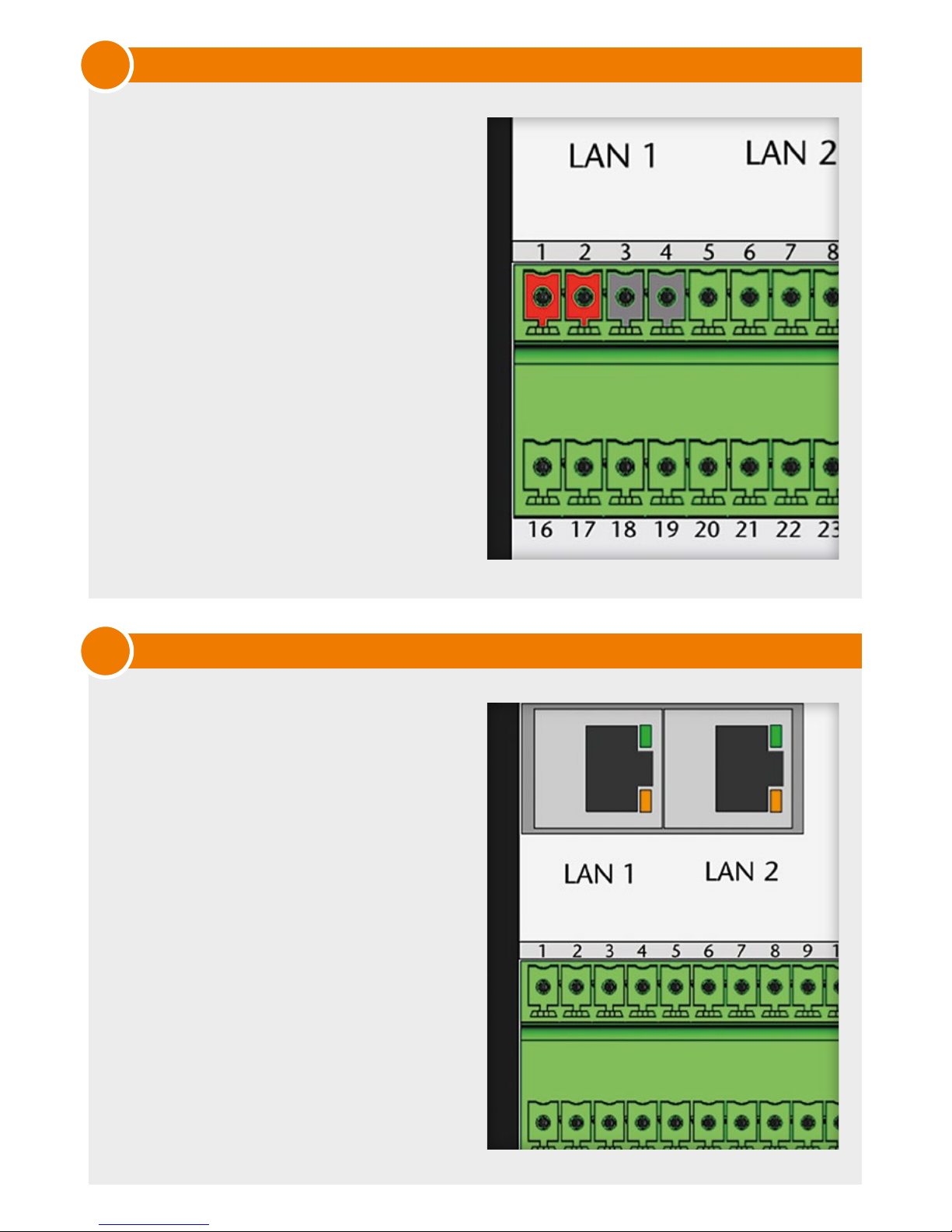
Connect DC voltage 9V..36V to the
accordingly marked terminals of the
µMIC.200.
The LED “PWR” shows a permanent
green light. A green flashing light of
“LED1” indicates access to the internal
flash memory.
Plug network wire into LAN1 or
LAN2 connector and connect it to
your computer.
Follow the instructions for standard
configuration:
IP address LAN 1: 192.168.2.100
IP address LAN 2: is determined
via DHCP
You can log into the µMIC.200
through the SSH protocol.
Login data:
User: umic
Password: umic
Power supply
Network interface
Page 3
3
4
4
1
7
5
2
3
6
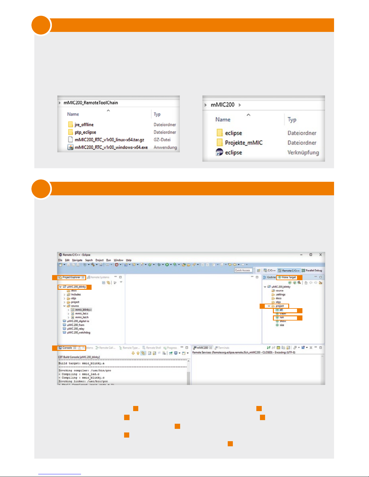
For remote development, use the preconfigured Eclipse which only requires a Java runtime
environment and a network connection to the µMIC.200.
Install the µMIC.200 Remote Tool Chain which corresponds your operating system from the
attached CD.
Navigate to the installation directory and execute „eclipse“.
The Eclipse GUI is structured to contain all necessary tools for remote development on
the µMIC.200.
Some sample projects have already been created for you. Set up a network connection
between the µMIC.200 and your computer and start development.
The Blinky project realizes a running light on LED1...LED4 using the colours red and green.
1) In view ‚Project Explorer‘ 1 double click the ‚µMIC.200_blinky‘ project
2
to open it.
2) In view ‚Make Target‘
3
you can now navigate to the directory ‚project‘ 4 and compile the
project by double clicking Make Target ‚all‘ 5.
3) Via Make Target ‚run‘ 6 you can execute the programme on the µMIC.200. The corresponding
output of the programme may be monitored in view ‚Console‘ 7.
Set up development environment
µMIC.200 Blinky project under Eclipse
Page 4
6
5
This document contains important information to facilitate a smooth start-up of your µMIC.200.
More helpful tips and tricks on the usage of the Automation Controller you will find in the µMIC.200
manual.
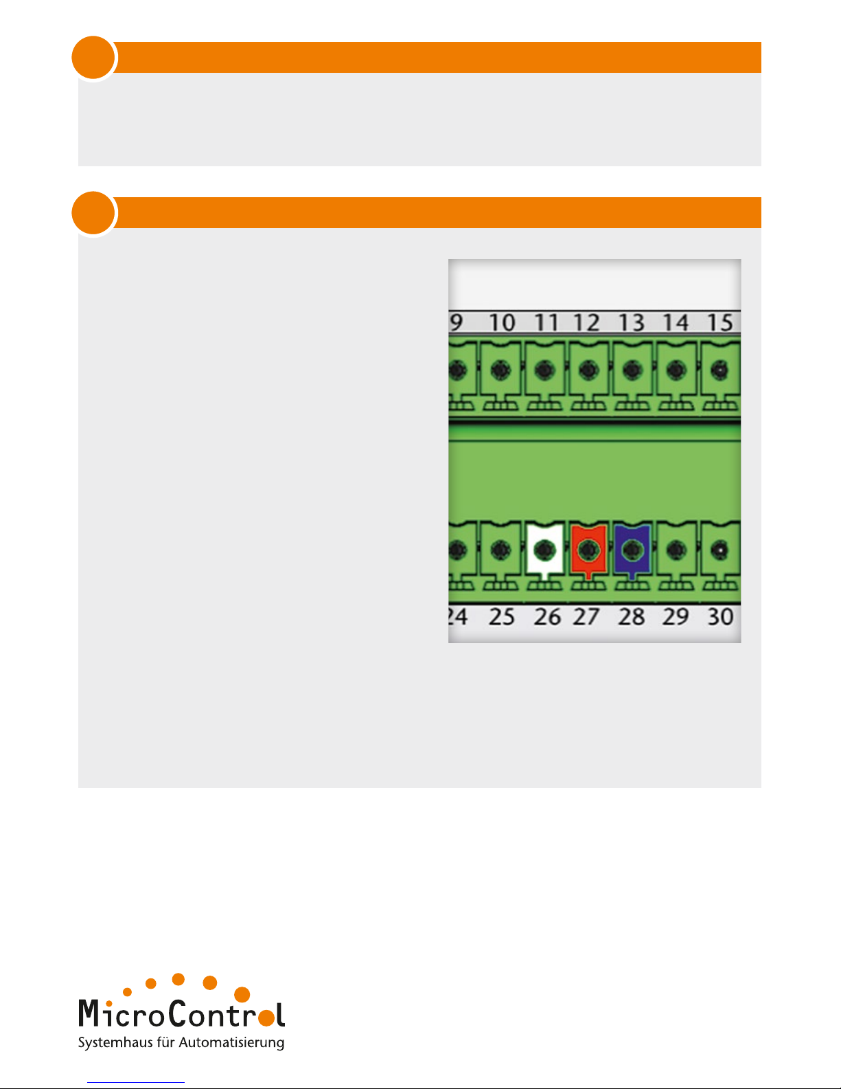
Serial Interface
Connect the serial cable to the terminals
according to the terminal denominations
in the picture.
Settings of the serial interface:
Bit rate: 115200Bit/s
Data bits: 8
Parity: none
Stop bits: 1
After the voltage has been applied Linux
will display log messages. You can now
log into the µMIC.200.
Login data:
User: umic
Password: umic
Example for log in via serial interface:
‚cd Examples/blinky/project/ && make &&
sudo ../objs/umic_blinky
The “blinky” programme is compiled and started. To execute the programme enter the
password “umic”.
The LEDs of the µMIC.200 are now flashing red and green in turn.
Option for Linux users
Junkersring 23
53844 Troisdorf
Germany
Tel.: +49(0)2241/25 65 9 - 0
Fax: +49(0)2241/25 65 9 - 11
[email protected]
www.microcontrol.net
Your µMIC.200 is now ready for use. Benefit from comfortable and highly efficient tools such as IEC
61131-3 or C/C ++ to integrate your new control system into your company-specific environment.
Develop now!
 Loading...