

Page 1

DAMS-NT DigiRIT
Digital LRIT/HRIT Receiver
Operation Manual
Release 1 - Revision A
12/14/2012
Microcom Design, Inc.
10948 Beaver Dam Road, Suite C
Hunt Valley, MD 21030
Page 2

Release 1 DAMS-NT DigiRIT Operation Manual 12/14/2012
Table of Contents
Table of Contents............................................................................................................................. i
List of Figures.................................................................................................................................ii
List of Tables .................................................................................................................................iii
List of Appendices.........................................................................................................................iii
1. Introduction............................................................................................................................ 4
1.1. Manual Organization .......................................................................................................... 4
1.2. Background......................................................................................................................... 4
1.3. Theory of Operation............................................................................................................ 6
1.3.1. DigiRIT Receiver Overview............................................................................................ 8
1.3.2. DAMS-NT DCP Message Interface ................................................................................ 9
1.3.2.1. DAMS-NT Message Header......................................................................................... 9
1.3.2.2. DAMS-NT Message Data........................................................................................... 12
1.3.2.3. DAMS-NT Carrier Times........................................................................................... 12
1.3.3. LRIT TCP/IP Interface .................................................................................................. 13
1.3.4. Antenna Front End Power.............................................................................................. 14
1.3.5. DAMS-NT DigiRIT General Power Requirements....................................................... 14
2. DAMS-NT DigiRIT Hardware Setup.................................................................................. 15
2.1. Antenna Installation.......................................................................................................... 15
2.2. DigiRIT Receiver Installation and Hardware Overview .................................................. 15
2.2.1. Front Panel Connections, Controls and Indication ........................................................ 16
2.2.1.1. Front Panel Display..................................................................................................... 16
2.2.1.1.1. Startup Screens.......................................................................................................... 16
2.2.1.1.2. Operational Status Screen......................................................................................... 16
2.2.1.2. Front Panel LEDs........................................................................................................ 18
2.2.1.3. Setup/Select Pushbuttons............................................................................................ 18
2.2.1.4. Test Port...................................................................................................................... 18
2.2.1.5. 70 MHz Test Connector.............................................................................................. 18
2.2.1.6. 140 MHz Test Connector............................................................................................ 19
2.2.2. Rear Panel Connections, Controls and Indications........................................................ 19
2.2.2.1. 70 and 140 MHz Antenna IF Groups.......................................................................... 19
2.2.2.1.1. Antenna In................................................................................................................. 19
2.2.2.1.2. Antenna IF Out ......................................................................................................... 19
2.2.2.2. DCS TCP/IP Network Connection ............................................................................. 20
2.2.2.3. LRIT/HRIT TCP/IP Network Connection.................................................................. 20
2.2.2.4. IRIG-B Input............................................................................................................... 20
2.2.2.5. Power Input and On/Off Switch ................................................................................. 20
2.2.2.6. Power Indicator........................................................................................................... 20
2.2.2.7. Ground Lug................................................................................................................. 20
2.2.2.8. Cooling Fan................................................................................................................. 21
3. DigiRIT Receiver Configuration ......................................................................................... 22
3.1. Front Panel Pushbutton Setup........................................................................................... 23
3.1.1. Selecting the IF Input..................................................................................................... 23
i
Page 3

Release 1 DAMS-NT DigiRIT Operation Manual 12/14/2012
3.1.2. Programming the IF Frequency ..................................................................................... 24
3.1.3. Setting the IF Attenuation.............................................................................................. 25
3.1.4. Enabling/Disabling the LNA (Front-End) DC Power ................................................... 25
3.1.5. Configuring the LRIT DCS Virtual Channels ............................................................... 26
3.1.6. Completing the Pushbutton Setup Process .................................................................... 27
3.2. Test Port Setup.................................................................................................................. 27
3.2.1. Test Port Status Report .................................................................................................. 28
3.2.2. Serial Test Port Menu System........................................................................................ 28
3.2.2.1. System Setup Menu .................................................................................................... 29
3.2.2.2. Virtual Channel Setup Menu ...................................................................................... 30
3.2.2.3. Message Setup Menu.................................................................................................. 31
3.2.2.3.1. Unknown Baud Rate Option..................................................................................... 31
3.2.2.3.2. Slot Number Mode Option........................................................................................ 32
3.3. Network Interface Configuration...................................................................................... 33
List of Figures
Figure 1: Major Elements of GOES DCS...................................................................................... 5
Figure 2: Typical DigiRIT System Block Diagram....................................................................... 6
Figure 3: DigiRIT Receiver Front Panel........................................................................................ 8
Figure 4: DigiRIT Receiver Rear Panel......................................................................................... 8
Figure 5: DigiRIT LRIT TCP/IP Processing ............................................................................... 13
Figure 6: DigiRIT Startup Screen Sequence................................................................................ 16
Figure 7: DigiRIT Status Screen.................................................................................................. 17
Figure 8: Accessing the Pushbutton Setup Mode ........................................................................ 23
Figure 9: Selecting the IF Input ................................................................................................... 23
Figure 10: Selecting the IF Frequency......................................................................................... 24
Figure 11: Setting the IF Attenuation .......................................................................................... 25
Figure 12: Turning the LNA Power ON and OFF....................................................................... 25
Figure 13: Selecting the LRIT DCS Virtual Channels ................................................................ 26
Figure 14: Adjusting the VC Buffer Allocations......................................................................... 26
Figure 15: Completing the Pushbutton Setup Sequence.............................................................. 27
Figure 16: Test Port Status Loop ................................................................................................. 28
Figure 17: Test Port Main Menu and System Information.......................................................... 29
Figure 18: System Setup Menu.................................................................................................... 30
Figure 19: Virtual Channel Setup Menu...................................................................................... 31
Figure 20: Message Setup Menu.................................................................................................. 32
Figure 21: MiiNePort Web Console – Overview Screen............................................................. 34
Figure 22: Web Console – Network Settings .............................................................................. 34
Figure 23: Web Console – Save/Restart...................................................................................... 35
Figure 24: Web Console – Operation Modes Settings................................................................. 35
Figure 25: Web Console – Settings Saved................................................................................... 36
ii
Page 4

Release 1 DAMS-NT DigiRIT Operation Manual 12/14/2012
List of Tables
Table 1: 55-Character DCP Message Header Format.................................................................. 10
Table 2: Error/Message Flag Values............................................................................................ 11
Table 3: DRGS Source Code to Slot Number ............................................................................. 33
List of Appendices
APPENDIX A: Acronyms and Abbreviations............................................................................. 37
iii
Page 5

Release 1 DAMS-NT DigiRIT Operation Manual 12/14/2012
1. Introduction
The Microcom Design, Inc. DAMS-NT DigiRIT system is an easy-to-use, low-cost solution to
receive satellite information from the National Oceanographic and Atmospheric
Administration’s (NOAA) Geostationary Operational Environmental Satellite (GOES) Data
Collection System (DCS) via the Low Rate Information Transmission (LRIT) re-broadcast. The
primary component is the Microcom DAMS-NT DigiRIT Receiver, which provides all the
necessary functionality to receive, demodulate, and process the LRIT data stream to extract and
deliver DCS messages in an industry standard DAMS-NT format. Beyond the DigiRIT Receiver
itself, all that is required to complete the DigiRIT system is a satellite dish and a computer or
server. The DigiRIT Receiver can be supplied with a satellite dish or the Receiver can be
coupled with an existing GOES satellite dish; typically as part of an existing Direct Readout
Ground Station (DRGS). Typically, the computer or server is provided by the end user; since the
DigiRIT Receiver provides TCP/IP network outputs, no special hardware. Microcom can
provide a LRIT DCS Client application, or the DCS data can be ingested into an existing
DAMS-NT compatible software package.
1.1. Manual Organization
This Operation Manual is divided into the following sections:
Section 1 provides introductory, background and theory of operation information.
Section 2 provides hardware installation and hardware overview information.
Section 3 provides information on configuring the DigiRIT Receiver for operation.
1.2. Background
The National Oceanic and Atmospheric Administration’s (NOAA) National Environmental
Satellite, Data, and Information Service (NESDIS) manages, operates, and maintains the U.S.
Geostationary Operational Satellite System (GOES). The GOES primary mission is to
continuously observe changing weather phenomena from satellite-based sensors situated
approximately 23,000 miles from Earth. The GOES supports an environmental data satellite
radio relay Data Collection System, (DCS). The GOES DCS allows a remote radio set or Data
Collection Platform (DCP), which is land, sea, or mobile based, to transmit through the GOES
DCS and back to NESDIS receive stations.
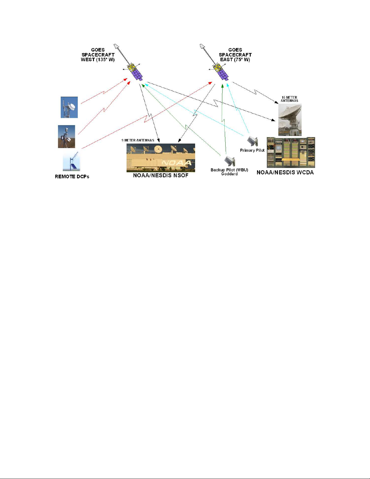
The principal components of the GOES DCS are shown in Figure 1 and consist of:
1. The geosynchronous spacecrafts (GOES East and GOES West);
2. NOAA’s Wallops Command and Data Acquisition station (WCDA) located at
Wallops Island, Virginia;
3. the NOAA Satellite Operational Facility (NSOF) located in Suitland, Maryland;
4. the Primary Pilot uplink from WCDA;
5. the Backup Pilot uplink from Wallops Back-Up site located at the Goddard
Spaceflight Center (GSFC), Greenbelt, Maryland; and
6. approximately 30,000 remote sensing Data Collection Platforms (DCPs).
Microcom Design, Inc. 4
Page 6
Release 1 DAMS-NT DigiRIT Operation Manual 12/14/2012
Figure 1: Major Elements of GOES DCS
The GOES DCS became operational more than 25 years ago and operates continuously, 24 hours
per day, 7 days per week. DCS messages are received at the two NESDIS sites by the Data
Acquisition and Monitoring Systems-New Technology (DAMS-NT) and forwarded to the DCS
Administration and Data Dissemination System (DADDS). From the DAMS-NT and DADDS
systems, GOES DCS messages are distributed to the GOES DCS user community through a
variety of dissemination paths.
The GOES spacecrafts are located at 75 W (GOES East) and 135 W (GOES West) longitude and
zero latitude positions at a geosynchronous altitude of approximately 23,000 miles above the
earth’s surface. The remote sensing DCPs transmit/uplink in the UHF band at frequencies
ranging from 401.7 MHz to 402.1 MHz. The respective spacecraft downlink is at 1694.3 MHz-
1694.7 MHz. It should be noted that these frequencies are reserved internationally for exclusive
use in this service.
To maintain GOES DCS channelization and frequency stability, and to provide an amplitude
reference, NOAA NESDIS uplinks two Pilot (or beacon) signals. The Primary Pilot is uplinked
at precisely 401.850 MHz from the WCDA. The Backup (or secondary) Pilot is uplinked at
401.700 MHz from the Wallops Back-Up (WBU) facility, at the Goddard Spaceflight Center
(GSFC), Greenbelt, Maryland. Both Pilots are radiated to both the East and West GOES
spacecrafts; NOAA personnel monitor and maintain the received signal level at the spacecraft to
be equivalent to 47 dBm EIRP. The pilot signals are used to remove the frequency uncertainty in
the satellite’s transponder in the channel.
GOES DCS data received by NESDIS is selectively routed to the appropriate system users via
communications links including Domestic satellite (DOMSAT), National Weather Service
Telecommunications Gateway (NWSTG), NOAA’s Low Rate Information Transmission (LRIT)
satellite link, a user developed Local Readout Ground System (LRGS) network, and the DADDS
Internet website. The NESDIS GOES DCS resource’s are allocated and administered by
NESDIS from the NSOF facility.
Microcom Design, Inc. 5
Page 7
Release 1 DAMS-NT DigiRIT Operation Manual 12/14/2012
1.3. Theory of Operation
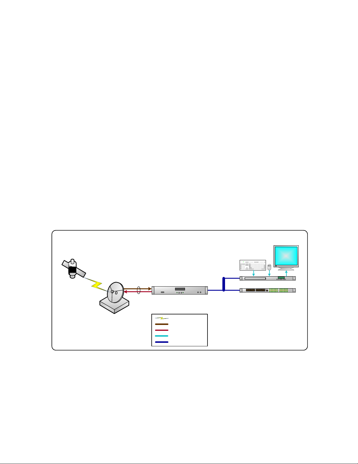
A typical Microcom DAMS-NT DigiRIT system diagram is shown in Figure 2. The ground
elements consist of a parabolic satellite antenna (or dish) complete with a GOES compatible
“front-end” or “feed”, the Microcom DAMS-NT DigiRIT Receiver, and the user’s computer
system. The space portion of the system is either the GOES-East or GOES-West satellite.
The LRIT signal originates at WCDA and is simultaneously broadcast to both the East and West
GOES satellites. The LRIT signal consists of several GOES products including the Emergency
Management Weather Information Network (EMWIN) alerts and notifications, various imagery
products, and the DCS re-broadcast. The DCS re-broadcast portion includes all messages
received by NOAA at WCDA.
The parabolic antenna receives the LRIT signal and focuses it on the “front-end”. The downlink
frequency of the LRIT signal is 1694.000 MHz, which is in the RF L-Band. Transmission in the
L-Band spectrum are relatively immune to weather fading and are not significantly affected by
cloud cover or rain storms.
The “front-end” or “feed” consists of a block down convertor and a low-noise amplifier (LNA).
Often the front-end is simply referred to as an LNA. The block down convertor translates the LBand signal to a lower frequency IF and the LNA boosts this signal before it is sent to the
DigiRIT Receiver. The DigiRIT Receiver can accept a wide range of IF frequencies so it is
compatible with numerous front-ends. Front-ends typically require a DC supply to operate and
the DigiRIT Receiver is capable of supplying 12 VDC over the same coaxial cable that returns
the IF signal.
GOES Satellite
(East or West)
Parabolic
Parabolic
ParabolicParabolic
Antenna
Antenna
AntennaAntenna
With
With
WithWith
Front
Front----End
End
FrontFront
EndEnd
Common
Common
Common Common
Coax
Coax
CoaxCoax
Microcom DAMS
Microcom DAMS----NT
Microcom DAMSMicrocom DAMS
DigiRIT Receiver
DigiRIT Receiver
DigiRIT ReceiverDigiRIT Receiver
Connection Legend
RF Signal
50 Ohm IF
DC Power
Digital or KVM
DAMS-NT TCP/IP
NT
NTNT
Private LAN
Private LAN
Private LANPrivate LAN
User Supplied Server
User Supplied Server
User Supplied ServerUser Supplied Server
User Supplied Network Switch
User Supplied Network Switch
User Supplied Network SwitchUser Supplied Network Switch
Figure 2: Typical DigiRIT System Block Diagram
The DigiRIT Receiver has two mutually exclusive IF inputs. One input is designated the 70
MHz IF Input and can accept a signal in the range of 50 to 90 MHz (70 ± 20 MHz). The second
input is the 140 MHz IF Input and covers a range from 126 MHz to 154 MHz (140 ± 14 MHz).
Only one of these inputs can be specified as the active input. Both inputs are capable of sourcing
a DC supply for the front-end. In most cases, the IF signal delivered by the front-end includes
both the raw DCS spectrum and the LRIT transmission, as well as numerous other GOES RF
Microcom Design, Inc. 6
Page 8

Release 1 DAMS-NT DigiRIT Operation Manual 12/14/2012
components. The raw DCS spectrum is located 450 kHz above the LRIT signal at 1694.450
MHz.
Generally speaking, the DigiRIT’s 70 MHz IF Input is intended to be utilized with Microcom’s
standard DRGS front-end, which allows a single satellite dish to provide an input to both the
LRIT DigiRIT Receiver and a local DCS DRGS. The 140 MHz input is generally utilized in a
stand-alone LRIT configuration. A DCS DRGS receiver typically requires a satellite dish in
excess of 3.5 meters in diameter, while the LRIT signal can be reliably received with a dish as
small as 1.2 meters.
In Microcom’s standard DRGS configuration, the DCS IF is at 74.450 MHz and the LRIT signal
is at 74.000 MHz. In a standalone LRIT receive system, Microcom typically utilizes a more
compact front-end that better fits on the smaller dish; this front-end provides the LRIT signal at
137.500 MHz.
Once the DigiRIT has acquired the LRIT signal, it will extract the DCS messages from the LRIT
stream and forward them out the DCS TCP/IP network connection as they are received. The
receiver’s DCS interface is compliant with the “DAMS-NT Network Interface Specification
V8.1”. However, only the “DCP Message Interface” socket is implemented. Since the “Event”,
“Real-Time Status”, and “Configuration” interfaces are more geared toward a DRGS, these
interfaces are not applicable to an LRIT DCS receiver.
A complete the LRIT DCS system requires a computer or server hosting a DAMS-NT
compatible Client application. Since the DigiRIT Receiver utilizes TCP/IP network
communications, no special hardware is required for the Client computer to ingest DCS
messages. While Microcom has its own DAMS-NT Client software, use of the DAMS-NT
interface socket means the DigiRIT Receiver is compatible with other DAMS-NT Client
applications. As such, the computer/server and host application can be provided by the end user.
For this reason, the standard Microcom DAMS-NT DigiRIT Receiver system does not include a
computer nor any application software; although these can be optionally provided.
Note that while Figure 2 only shows a single computer, the DigiRIT Receiver can support up to
three DAMS-NT Client connections. These Client connections can be separate computers
hosting unique applications, a single computer hosting multiple Client applications, or a
combination of these provided the total number of socket connections is limited to three.
Finally, it should be emphasized that since the DCS re-broadcast provides complete channel
coverage and since the LRIT stream is transmitted to both satellites, a single satellite dish
pointed at either the East or West spacecraft is sufficient to collect all DCS messages routed
through the GOES system and received by NOAA. To a yield a similar result utilizing a
traditional DRGS not only requires two satellite dishes and accompanying front-ends, but also
requires a substantial amount of additional hardware and software to receive all of the more than
200 active DCS channels (soon to double to more than 400 in the coming years). In other words,
a simple, low-cost LRIT DCS system pointed at just one GOES satellite, as is possible with the
Microcom DigiRIT Receiver, can yield total GOES DCS message reception at a fraction of the
complexity and cost of a complete DRGS.
On the other hand, while it is not necessary to get the LRIT stream from both spacecrafts, there is
one distinct advantage to utilizing two DigiRIT systems, one for GOES-East and one for GOESWest; specifically, redundancy. Adding a second DigiRIT antenna and receiver to get the LRIT
Microcom Design, Inc. 7
Page 9
Release 1 DAMS-NT DigiRIT Operation Manual 12/14/2012
stream from the alternate satellite means that there is no single point of failure anywhere in the
LRIT DCS transmission/reception chain, including the spacecraft itself. Since NOAA has
numerous layers of redundancy in both the DCS and LRIT systems, by receiving the LRIT signal
from both spacecrafts means no DCS message that can be received will be lost due to a single
failure in the user’s ground system.
1.3.1. DigiRIT Receiver Overview
The DigiRIT receiver is housed in a standard 19” rack mount enclosure. The height is 2RU and
the depth is approximately 14.5”. All primary connections are provided on the rear panel, while
various test connections and controls are provided on the front panel.
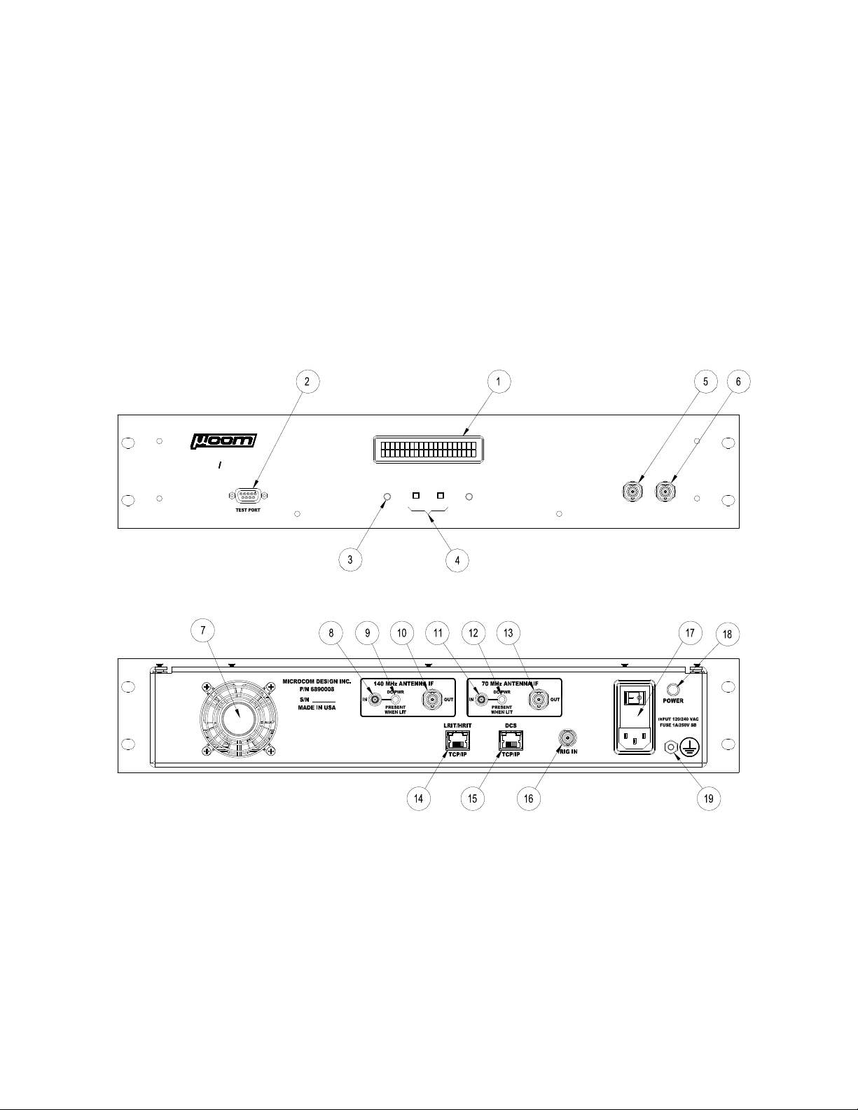
Figure 3 shows the front panel of the DigiRIT, while Figure 4 shows the DigiRIT’s rear panel.
As the figures below indicate, numerous connections for both operation and test are provided.
The use and functionality of these connections is detailed in Section 2 of this manual.
DAMS-NT DigiRIT
DIGITAL LRIT HRIT RECEIVER
70 MHz
TEST
140 MHz
TEST
SIGNAL
ACQUIRED
SELECTSETUP
CLIENT
CONNECTED
Figure 3: DigiRIT Receiver Front Panel
Figure 4: DigiRIT Receiver Rear Panel
Referring to the above figures, provided below is a list of the DigiRIT’s connection points,
controls, and indicators.
1. Status Display N/A
2. RS-232 Test Port SUB-D-9F
3. LED Status Indicators N/A
4. DigiRIT Setup Pushbuttons N/A
Microcom Design, Inc. 8
Page 10

Release 1 DAMS-NT DigiRIT Operation Manual 12/14/2012
5. 70 MHz IF Test Point BNC
6. 140 MHz IF Test Point BNC
7. Cooling Fan N/A
8. 140 MHz Antenna IF Input Connector SMA
9. 140 MHz Front End DC Power Indicator LED N/A
10. 140 MHz Antenna IF Output Connector SMA
11. 70 MHz Antenna IF Input Connector SMA
12. 70 MHz Front End DC Power Indicator LED N/A
13. 70 MHz Antenna IF Output Connector SMA
14. Raw LRIT/HRIT Network Connector RJ-45
15. DCS Message Network Connector RJ-45
16. IRIG-B Timing Input BNC
17. AC Power Input with On/Off Switch IEC320-C14
18. Power Indicator Lamp N/A
19. Ground Lug Stud
1.3.2. DAMS-NT DCP Message Interface
While complete details of the “DCP Message Interface” can be found in the “DAMS-NT Network
Interface Specification V8.1”, this section provides a brief overview of this interface and
addresses some minor deviations from the specification.
The DCP Message Interface provides a mechanism for multiple clients to receive DCS messages
from the DigiRIT unit. While multiple client connections are supported by the DigiRIT
Receiver, the maximum number of Client connections is limited to three (3). The DCP Message
Interface is a one-way stream of DCS messages. After a client establishes a connection, the
DigiRIT immediately begins to send DCS messages as they become available, i.e. the DAMSNT Client does not poll for messages.
If no DCS message is received via the LRIT stream for more than 10 seconds since the last
message was sent to a client, the DigiRIT will send the keyword “NONE” followed by a CR/LF
to allow clients to detect the difference between a dead socket and the case where no new data is
available, as often happens in the LRIT DCS re-broadcast while LRIT system is transmitting
another product.
Each DCS message is sent the connected Clients after it is received via the LRIT stream and
after the message has been validated. Valid DCS messages are translated from their native LRIT
DCS structure and are re-formatted per DAMS-NT DCP Message Interface. This format
includes a 55-byte header, followed by the actual message data, followed by a CR/LF, and
possibly followed the V8.1 carrier times.
1.3.2.1. DAMS-NT Message Header
The DigiRIT creates a 55-byte header compatible with the DAMS-NT format, which is
summarized in the table below. However, minor deviations from the specification imposed by
limitations in the raw LRIT message format are discussed below. All fields, including the
StartPattern, in the header are in ASCII without any parity.
Microcom Design, Inc. 9
Page 11

Release 1 DAMS-NT DigiRIT Operation Manual 12/14/2012
While the DAMS-NT specification allows the StartPattern to be configured, this is not possible
in the DigRIT since the Configuration Interface is not implemented. As such, the start pattern
has been hard coded based on the de facto standard. While the DAMS-NT specification allows
for any four binary byte values, most DAMS-NT sites are configured to use the hexadecimal
pattern 0x534D0D0A that correlates to the ASCII characters “SM” (i.e. Start Message) followed
by a CR/LF. In addition to being compliant, use of this pattern in the DigiRIT also means the
entire header is ASCII.
Table 1: 55-Character DCP Message Header Format
Ofs Name Len Format Description
0 StartPattern 4 String “SM”+CR+LF (0x534D0D0A)
4 SlotNum 3 Digits-Zero Filled LRIT Virtual Channels
7 Channel 3 Digits-Zero Filled DCS Spectrum Channel Number
10 Spacecraft 1 Character ‘E’ or ‘W’
11 Baud 4 Digits-Zero Filled See Below
15 StartTime 11 YYDDDHHMMSS UTC Time of message start (i.e. frame
synch)
26 SignalStrength 2 Digits-Zero Filled Signal strength in dB
28 FreqOffset 2 +/- 1 Digit Sign character followed by 1 digit. In
units of 50Hz
30 ModulationIndex 1 ‘N’, ‘H’, or ‘L’ N=normal, H=high, L=low
31 DataQuality 1 ‘N’, ‘F’, or ‘P’ N=normal, F=fair, P=poor
32 ErrorFlags 2 Hex Characters 2 Hex characters representing up to 8 bit-
error or message flags. See Table 2.
34 OrigAddress 8 Hex Characters DCP Address – See Below
42 DcpAddress 8 Hex Characters DCP Address – See Below
50 Length 5 Digits-Zero Filled Number of message bytes to follow
The slot number field, in the DAMS-NT specification corresponded to “demodulator slots” that
could be tuned to any DCS channel. In the DigiRIT, this value can be configured to supply one
of three types of values (see Section 3.2.2.3). The default setting is to fill this filed with the
LRIT Virtual Channel (VC) the message was received on. The LRIT specification provides for
64 virtual channels to be used by different products, and within a product group by different
priorities. Currently, DCS messages utilize three of these Virtual Channels based on a priority
scheme. As such, this zero-filled, numeric field typically correlates the LRIT VC to the “slot
number”. The other two user configurable options for this field are a received sequence count
number or a DRGS source code identifier; see Section 3.2.2.3 for more information on these two
options.
The Channel is the numerical value of the DCS channel the message was received on. This
information is provided in the LRIT stream and is simply copied verbatim.
The Spacecraft field designates the GOES satellite the message was received on, East or West.
Note this is the spacecraft the original DCS message was transmitted through, not the LRIT
spacecraft. As with the Channel field, the information is provided via the LRIT data and is
simply copied.
Microcom Design, Inc. 10
Page 12

Release 1 DAMS-NT DigiRIT Operation Manual 12/14/2012
The Baud field is provides the data rate of the received message if it is available. For most
messages, this information is provided in the LRIT stream. However, for some messages this
information is not provided and the DigiRIT has no way to determine this value. Typically, the
messages that do not have the message baud rate are those that are system generated for
informational purpose, e.g. a missing message.
When the DigiRIT receives a message without the Baud rate, an optional setting (see Section
3.2.2.3) in the DigiRIT allows this field to be filled with all zeroes indicating it is unknown, or to
be filled in with a valid DCS Baud value. Testing with various applications has shown that some
DAMS-NT Clients report an error if this field is not a data rate currently in use in the DCS. As
such, the default setting for the DigiRIT is to this fill this field with the most common valid value
of ‘0300’ if the Baud rate is not included with the message.
The StartTime is de facto standard message start time which correlates to the reception of the
DCS message frame synchronization, i.e. when the message data begins. This time stamp is only
reported with a resolution of one second and is provided in the LRIT data.
The SignalStrength, FreqOffset, ModulationIndex, and DataQuality fields are all reported and
simply captured from the LRIT message data. These legacy fields have been around for some
time and should be well known and understood by most DCS users.
The ErrorFlags field in the message header contains two hex digits of message-specific bits
and/or error flags. This field is represents a combination of 8 one-bit binary values, where a bit
set to one means the corresponding attribute is true. Table 1 contains the bit-mapped definition
for this field.
Bit 0 is set to true if the DCS message received had parity errors; this fact is determined prior to
the message is re-broadcast in the LRIT feed and is indicated by a special character in the LRIT
header. This character is designated the Abnormal Received Message (or ARM) character; if
this character is a ‘?’, the message contained parity errors and the flag is set accordingly.
Bits 1 and 2 are reserved for future use and are currently never set to one.
Bit 3 indicates a valid EOT (End Of Transimission) was not received as part of the DCS
message. Currently this information is not provided in the LRIT data stream so this flag bit will
never be set.
Bit 4 indicates that the message does indeed contain the optional Carrier Times; see Section
1.3.2.3 below.
Table 2: Error/Message Flag Values
Bit Bit Value Meaning
0 0x01 Message contains parity errors.
1 0x02 Binary message (future use)
2 0x04 Binary message with bit errors (future use).
3 0x08 Loss of lock termination (i.e., no EOT)
4 0x10 Message contains Carrier Times
The OrigAddress and DcpAddress will contain the same information; specifically, the GOES
DCS Platform ID or Address that transmitted the message. The GOES DCP ID is an eight
Microcom Design, Inc. 11
Page 13

Release 1 DAMS-NT DigiRIT Operation Manual 12/14/2012
character hexadecimal field that represents a 31-bit BCH code. The BCH code allows for error
correction of up to two bits in the received platform address. In a DRGS, the raw received ID is
reported in the OrigAddress field, while the DcpAddress field contains the BCH corrected
address. In the LRIT data stream, only the corrected address is sent; however, since DAMS-NT
Clients expect both of these the fields to be populated, they both contain the LRIT received
corrected address.
The Length field contains a zero filled 5-digit value that reports the number of received bytes in
the message. This value is used to determine the number of message bytes/characters that will
follow the header.
1.3.2.2. DAMS-NT Message Data
The message portion of the DAMS-NT DCP Message Interface contains the actual message data.
This data will contain the actual data received in the LRIT stream “as is”, i.e. there is no
character substitution or parity bit removal. However, since the LRIT data stream is a rebroadcast of the DCS messages, character substitution and parity bit removal may have already
taken place at NOAA.
As of the release date of this manual, the LRIT stream does remove the parity bits in the message
data. Further, certain “invalid characters” and bytes with parity errors are substituted with a ‘$’
character. The invalid or prohibited characters replaced are those defined in “Version 1.0B of
the 300/1200 BPS GOES Data Collection Platform Radio Set (DCPRS) Certification
Standards”. Please contact NOAA for the latest information on parity checking and character
replacement in the LRIT DCS re-broadcast. Again, the DigiRIT Receiver does not perform and
parity checks or character substitution; it will transmit the message data as it is received in the
LRIT stream.
The number of bytes/characters in the message portion is defined by the Length field in the
DAMS-NT Header (see previous Section).
Following the received DCS message data is a CR/LF sequence. Note that DCP messages can
(and frequently do) contain embedded and terminating CR/LF patterns. The CR/LF at the end of
the DAMS-NT Message Data section is in addition to all received message bytes/characters and
is not counted in the message Length field in the DAMS-NT Header.
1.3.2.3. DAMS-NT Carrier Times
The Carrier Times provide time stamps with a millisecond resolution that indicate when the
signal or carrier was first detected (CarrierStart), and when the signal or carrier went away or
was “dropped” (CarrierDrop). These time stamps provide the most accurate indication of
whether or not the DCP is transmitting within its assigned time slot.
The time format for the CarrierStart and CarrierDrop fields is similar to the message StartTime
in the DAMS-NT Header (see Section 1.3.2.1), but includes 3 additional digits for the
millisecond resolution, i.e. the Carrier Times format is YYDDDHHMMSSsss, where the “sss”
portion indicates the sub-second to a millisecond.
If the Carrier Times are included, they will immediately follow the CR/LF that terminates the
message data portion. The format the for the Carrier Times section is CarrierStart followed by a
single space followed by CarrierDrop followed by a CR/LF. Further, whenever the Carrier
Microcom Design, Inc. 12
Page 14
Release 1 DAMS-NT DigiRIT Operation Manual 12/14/2012
Times are included, Bit 4 of the ErrorFlags field in the DAMS-NT Header will be set (see
Section 1.3.2.1).
As with many of fields in the DAMS-NT DCP Message Interface, the DigiRIT Receiver cannot
determine the Carrier Times, they must be present in the LRIT stream to be reported. Currently,
the LRIT stream appears to include this information on all messages except “informational”
messages. Informational messages are pseudo DCS messages created by the NOAA receive
system(s) that are sent out to notify the owner of a platform that some anomaly was detected, e.g.
a “missing message” or a message “outside of its assigned time window”; since these are system
generated messages, Carrier Times are not applicable.
The important point here is that the DigiRIT will report the Carrier Times if there are present in
the LRIT DCS message stream, and can not if they are not present. In either case, the Carrier
Times bit in the ErrorFlags field in the Header will be set accordingly.
1.3.3. LRIT TCP/IP Interface
While the primary intention of the Microcom DigiRIT Receiver is to extract DCS messages from
the LRIT stream and re-format them per the “DAMS-NT Network Interface Specification” (see
Section 1.3.2), the DigiRIT Receiver also provides a separate LRIT TCP/IP interface to allow
access to the full LRIT data stream. Primarily intended for custom developers, this interface is
provided via a separate network connector with a different IP address.
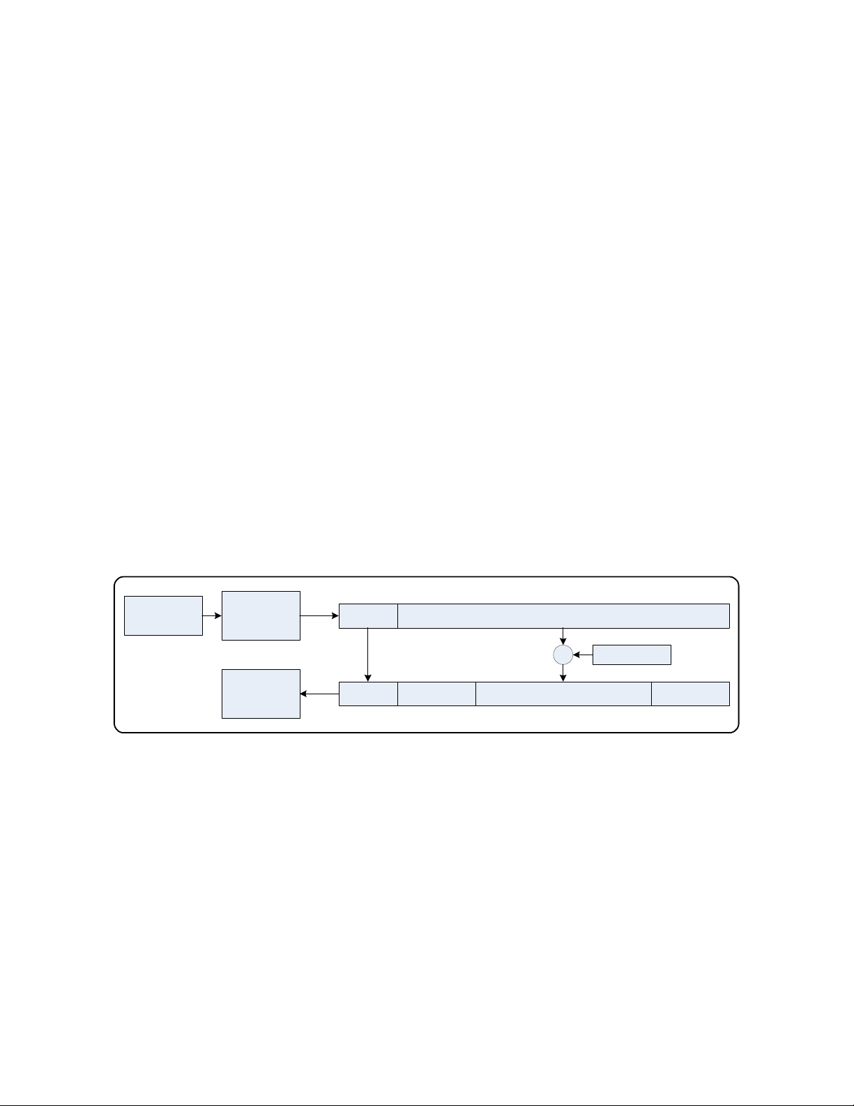
With a few notable exceptions, this interface is essentially the raw LRIT transmission. Figure 5
shows a block diagram of the LRIT TCP/IP interface processing. The most obvious exception is
that the network interface is byte-wise oriented while the raw LRIT signal transmits data in a bitwise fashion.
BPSK
Demod
~293 kbits/sec
Viterbi
Decoder
Rate ½
~146.5 kbits/sec
VCDU
LRIT TCP/IP
Interface
16 kbytes/sec
32 bits 8160 bits
1ACFFC1D
1ACFFC1D
4 bytes 6 bytes 886 bytes 128 bytes
VCDU Primary
Header
Scrambled Data
++++
VCDU Data Zone
Descrambler
Reed Solomon
Check Symbols
Figure 5: DigiRIT LRIT TCP/IP Processing
The BPSK signal is first demodulated into a bit-wise data stream at approximately 293 kilobits
per second. The DigiRIT first applies a Rate ½ Viterbi Forward Error Correction Decoder to the
incoming stream, which results in a reduced bit stream of about 146.5 kilobits per second. The
LRIT data is framed into 8192 bits or 1024 bytes. Each frame begins with a specific 32-bit or 4byte pattern as shown in Figure 5.
Once the DigiRIT identified two frame synchronization patterns spaced 8160 bits apart, it
declares it has frame sync and begins processing data. After the 4-byte frame sequence is 8160
bits or 1020 bytes of “scrambled” data. The DigiRIT applies the LRIT defined descrambler to
the data to produce what is called the Virtual Channel Data Unit or VCDU. Each VCDU
consists of a 6-byte header, an 886-byte data zone, and 128 bytes of Reed Solomon encoded
check symbols.
Microcom Design, Inc. 13
Page 15

Release 1 DAMS-NT DigiRIT Operation Manual 12/14/2012
Following this processing, each 1024 byte VCDU frame, complete with the 4-byte frame sync
sequence, is forwarded to the LRIT TCP/IP Interface. The additional processing of the VCDU
required to extract DCS messages and other LRIT products is beyond the scope of this manual,
but can be readily located on various NOAA websites.
Note that while the DigiRIT processes the LRIT data, it also continues to monitor for frame
synchronization. If frame sync is ever lost, data will discontinue to flow out the LRIT TCP/IP
interface. Further, it should be emphasized that while the DigiRIT Receiver only sends DCS
message information out the DAMS-NT DCS interface, all LRIT VCDU frames, regardless of
the associated product, are sent out the LRIT interface. This also includes Fill frames, Fill
frames are sent on Virtual Channel 63 and are sent whenever the LRIT system has no product
information to transmit.
1.3.4. Antenna Front End Power
The DigiRIT can be configured to optionally provide DC Power at the Antenna In connectors to
be utilized to power the satellite dish’s front-end. The DC output is nominally 12 VDC and can
safely source 0.75 Amps. A series self-resetting 1.1 Amp polyfuse is included for protection in
each Antenna In path.
The DC power at the Antenna In connectors can be enabled and disabled as discussed in Sections
3.1.4. As shown in Figure 4, an LED is provided next to each Antenna In connector on the rear
panel of the unit to alert the user when DC is present.
NOTE: When using a DigiRIT with the Antenna Front End Power option enabled, the
Antenna In connection should not be connected to anything other than the satellite
dish front-end. While the DC Power path is fused, back feeding 12 VDC @ 1A
into many devices can damage them.
1.3.5. DAMS-NT DigiRIT General Power Requirements
The Microcom DAMS-NT DigiRIT Receiver requires an AC power source, but can accept an
input voltage range of 100-240 VAC at either 50 or 60 Hz. While the AC Power Input and
On/Off switch (see Section 2.2.2.5) also includes an integral 1 Amp Fuse, the maximum power
required is less than 30 Watts.
Microcom Design, Inc. 14
Page 16

Release 1 DAMS-NT DigiRIT Operation Manual 12/14/2012
2. DAMS-NT DigiRIT Hardware Setup
2.1. Antenna Installation
If the DAMS-NT DigiRIT system includes an optional satellite antenna, it must be installed and
aligned for proper operation.
To install the satellite dish, follow the third party manufacturer’s installation instructions
provided with the dish.
Once the dish is installed, mount the front-end to the dish following the satellite dish and frontend manufacturers’ instructions.
To align the dish, three things must be known: 1) the elevation angle, 2) the azimuth compass
pointing direction, and 3) the polarity skew. All three of these items are a function of the
location of the dish and the desired GOES satellite that will be utilized to receive the LRIT
signal. Microcom recommends utilizing the website www.DishPointer.com to determine the
required pointing information. This website allows the user to enter the location of the dish
either by a street address or by latitude/longitude coordinates and provides a drop-down list of
geosynchronous satellites, including GOES-East and GOES-West. DishPointer also has
numerous SmartPhone applications available (for a small cost) to facilitate the dish alignment
process.
Once the required pointing information is known, the first step is to set the elevation using an
inclinometer; LRIT receive systems utilize a prime focus dish so the angle of the dish should
exactly match the elevation angle. If the azimuth is going to be set using a compass, be sure to
utilize the “magnetic” direction, not the “true” direction. Alternately, the DishPointer website
and applications provide a line-of-site indication overlaid on a satellite map, which allows
accurate azimuth alignment by simply selecting a distinct object to point the dish at.
The front-end or feed polarity is set by loosening its mounting hardware and rotating it to match
the polarity angle or “LNB/LNA Skew” accordingly. Note that polarity angles or skews are
relative to the sky view, i.e. looking through the dish/front-end at the satellite, and can have
positive (clockwise) and negative (counter-clockwise) values. However, most feeds have their
polarity indication on the back side of the unit, so one typically sets them while looking at the
dish. One must be sure to take this direction reversal into account when setting the polarity from
the back-side of the feed.
Once the dish and front-end are installed and aligned, all the remains is to connect the RF coaxial
cable to the feed. Typically, the feeds require the cable to be terminated in an N style connector;
consult the front-end manufacture’s information for the proper connector. Most front-ends
require a DC power source, which is supplied via the same coax cable the returns the LRIT
signal.
2.2. DigiRIT Receiver Installation and Hardware Overview
The Microcom DigiRIT Receiver requires very little hardware setup beyond performing the
connection of the various cables. Further, if the user provides Microcom with the necessary
information, the DigiRIT Receiver will be factory configured to be plug-and-play. For most
installations, only two cable connections will be required at the receiver besides AC Power.
Specifically, an Antenna IF Input connection and the DCS TCP/IP connection.
Microcom Design, Inc. 15
Page 17
Release 1 DAMS-NT DigiRIT Operation Manual 12/14/2012
The following sections provide additional information on the various hardware connections,
controls and indications.
2.2.1. Front Panel Connections, Controls and Indication
The Front Panel of the DigiRIT provides various status indicators, two push buttons, and three
test point connectors as shown in Figure 3.
2.2.1.1. Front Panel Display
The DigiRIT front panel display provides status information and is utilized when configuring the
setup of the unit via the front-panel push-buttons. While the status information is covered in this
section, setup is covered in Section 3.1.
2.2.1.1.1. Startup Screens
When the DigiRIT is first powered up, it will display a series of messages indicating the various
stages of its start up process. Figure 6 shows the sequence of display screens. The second screen
provides the firmware version of the unit and its four-digit serial number. Following this, the
DigiRIT requires a brief period of time to warm-up and let the RF circuits stabilize before it is
configured for operation. The total startup and configuration sequence takes approximately 10
seconds to complete. Configuration information is automatically saved to non-volatile memory
and recalled whenever the Receiver is powered up, i.e. the unit should always come up in the
same operational state as it was in prior to shutdown or power loss.
MICROCOM DESIGN INC
MICROCOM DESIGN INC
MICROCOM DESIGN INCMICROCOM DESIGN INC
DAMS
DAMS ----NT DigiRIT RCVR
DAMSDAMS
com LRIT Receiver
com LRIT Receiver
com LRIT Receiver com LRIT Receiver
V
V1111....00
V V
SYSTEM WARMUP
SYSTEM WARMUP
SYSTEM WARMUP SYSTEM WARMUP
PLEASE WAIT
PLEASE WAIT ...
PLEASE WAIT PLEASE WAIT
CONFIGURING UNIT
CONFIGURING UNIT
CONFIGURING UNIT CONFIGURING UNIT
PLEASE WAIT
PLEASE WAIT ...
PLEASE WAIT PLEASE WAIT
NT DigiRIT RCVR
NT DigiRIT RCVRNT DigiRIT RCVR
00 SSSS////N
00 00
N 1000
1000
N N
10001000
...
......
...
......
Figure 6: DigiRIT Startup Screen Sequence
2.2.1.1.2. Operational Status Screen
Once the unit is configured and ready for operation, it will provide continuous operational status
information similar to that shown in Figure 7.
The top line provides a summary of the Input Settings.
First is the actual programmed IF Frequency. If this frequency is between 50-90 MHz, the
receiver is operating on the 70 MHz IF Input; if it is between 126-154 MHz, then the 140 MHz
IF Input is being utilized.
After the frequency is the input attenuation; the DigiRIT receiver includes a 0-30 dB attenuator
programmable in 2 dB steps so the user can ensure the signal level is within range.
Microcom Design, Inc. 16
Page 18

Release 1 DAMS-NT DigiRIT Operation Manual 12/14/2012
Finally, the top line indicates if it is providing the LNA (or feed) with Power (LP=1) or not
(LP=0).
Input Settings
IF Frequency Atten Power
137
137....500
137137
----46
Signal Level RS Score
500MHz
MHz 10
500500
MHz MHz
46....1111dBm
4646
dBm 100
dBm dBm
Receiver Status
10dB LP
dB LP====1111
1010
dB LPdB LP
100%%%%RS
100100
RS 1
RS RS
1 FS
FS
1 1
FSFS
Clients
State
Figure 7: DigiRIT Status Screen
The bottom line provides active receiver status on the incoming signal.
First is the input signal level indication in dBm. The DigiRIT Receiver will accept an input
signal range of –90 to –20 dBm. However, the nominal signal presented to the demodulator
circuitry should be between –90 to –50 dBm. As such, if the nominal input signal is above –50
dBm then input attenuation (see Section 3.1.3) should be used to reduce signal strength presented
to the demodulator. The signal level reported is always referenced to the input of the unit and is
not the level input to the demodulator so changing the attenuator will not necessarily change the
reported signal level. In the example of Figure 7, the reported signal level is –46.1 dBm and the
attenuation is set to 10 dB; this means that the demodulator signal level is –56.1 dBm, which is
in the nominal range.
Next is the Reed Solomon (RS) score. If the signal quality is good, then the receiver should
always report a RS score of 100% indicating that each and every LRIT frame has valid Reed
Solomon Check Symbols. Occasionally, this value may drop below 100% indicating that some
LRIT frames required use of the RS encoding to correct a frame or two, but this should be
extremely infrequent. In other words, any continuous value below 100% range indicates a poor
signal quality.
The Clients digit reports the number of currently connected Clients (0-3). If this number is 0,
then the CLIENT CONNECTED LED (see Section 2.2.1.2) will be red; otherwise, it will be
green.
The final piece of status information provided in the display is the Receiver State. This twocharacter string indicates the demodulator lock status, where …
• UL => the demodulator is unlocked (not tracking the LRIT carrier)
• LK => has locked on to the LRIT carrier
• VS => has achieved Viterbi sync
• FS => has acquired LRIT frame sync
Once the receiver DigiRIT Receiver had acquired frame sync, it is capable of receiving DCS
messages and the SIGNAL ACQUIRED LED will turn from red to green.
Microcom Design, Inc. 17
Page 19

Release 1 DAMS-NT DigiRIT Operation Manual 12/14/2012
2.2.1.2. Front Panel LEDs
Also located on the front panel are two status LEDs. These two LEDS, are intended to provide
the user with a quick determination of the status of the DigiRIT Receiver, especially from a
distance. While the information indicated by these two LEDs is also reported in the front panel
display, the display is not generally readable from more than a few feet. However, the
Red/Green nature of the LEDs can often be determined by a greater distance.
As explained in the previous section, the SIGNAL ACQUIRED LED will turn green once the
receiver has acquired the LRIT signal and achieved frame synchronization. Once this occurs, the
receiver is able to fully process the LRIT stream and extract any DCS messages that are
transmitted.
The CLIENT CONNECTED LED will turn green when at least one Client is connected to the
DCS TCP/IP interface.
In summary, if the DigiRIT Receiver is receiving LRIT data and capable of forwarding DCS
messages to a DAMS-NT Client, both LEDs will be green indicating a fully functional state.
2.2.1.3. Setup/Select Pushbuttons
Located on the front panel in between the two stat LEDs are two pushbuttons, which are used to
configure the DigiRIT receiver for operation. Please refer to Section 3.1, for details on the use of
these buttons..
2.2.1.4. Test Port
The front panel Test Port is designed to be utilized with an ASCII terminal application and is
primarily intended for troubleshooting and diagnostic functions. The communications protocol
utilizes a simple menu interface that is compatible with a wide variety of commercially available
terminal programs (e.g. HyperTerminal). The DigiRIT receiver is designed to interface directly
to a PC’s standard 9-pin Sub-D serial port via a straight-through patch cable; i.e. do not use a
null modem cable. It should also be noted also that only pins 2, 3, and 5 (i.e. TXD, RXD, and
GND) of the serial port interface are actually utilized .
Communication parameters for the RS-232 Test Port are 8 data bits, no parity, and 1 stop bit
with a BAUD rate of 19,200 bps.
While the primary purpose of the Test Port is diagnostic purposes, as noted above, the Test Port
also be utilized to configure the DigiRIT in place of the front panel pushbuttons as detailed in
Section 3.2.
2.2.1.5. 70 MHz Test Connector
The 70 MHz IF Test connection provides a buffered output of the 70 MHz IF Input signal, if one
is present. This test connector is primarily provided to allow an easy connection point for
monitoring the 70 MHz IF on a Spectrum Analyzer.
Note that even when DC power is provided to the 70 MHz Antenna Input, the DC is NOT
present on the 70 MHz Test connector.
Microcom Design, Inc. 18
Page 20

Release 1 DAMS-NT DigiRIT Operation Manual 12/14/2012
2.2.1.6. 140 MHz Test Connector
The 140 MHz IF Test connection provides a buffered output of the 140 MHz IF Input signal, if
one is present. This test connector is primarily provided to allow an easy connection point for
monitoring the 140 MHz IF on a Spectrum Analyzer.
Note that even when DC power is provide to the 140 MHz Antenna Input, the DC is NOT
present on the 140 MHz Test connector.
2.2.2. Rear Panel Connections, Controls and Indications
The Rear Panel of the DigiRIT primarily provides the operational connection points for the unit.
However, a few additional controls and indicators are also included on the Rear Panel as shown
in Figure 4.
2.2.2.1. 70 and 140 MHz Antenna IF Groups
As discussed in Section 1.3, the DigiRIT Receiver can utilize either a 70 MHz (±20 MHz) or a
140 MHz (±14 MHz) IF input. Located on the Rear Panel are two similar groups of two
connections and an indicator LED that are identical in their functionality, except for the
aforementioned operating frequency.
Generally speaking, the 70 MHz IF is utilized when adding a DigiRIT Receiver to an existing
Microcom DRGS installation, while the 140 MHz IF is used in a stand-alone LRIT system.
The DigiRIT Receiver will accept an input signal range of –90 to –20 dBm. However, the
nominal signal presented to the demodulator circuitry should be between –90 to –50 dBm. As
such, if the nominal input signal is above –50 dBm then input attenuation (see 3.1.3) should be
used to reduce signal strength presented to the demodulator.
2.2.2.1.1. Antenna In
The 70/140 MHz Antenna In requires a cable terminated in a male SMA connector. The SMA
connector’s integral screw threads ensure a secure connection. The antenna input signal will
typically come from a satellite dish’s front-end or feed. In addition to the GOES LRIT signal,
several other GOES signal components will most likely be present in the input.
The DigiRIT’s Antenna In can also provide DC power to an external feed or dish front end. See
Section 1.3.4 for cautions and additional information on using the DigiRIT to power the front
end. When DC power is present at the 70/140 MHz Antenna In connection, the associated power
LED will be illuminated.
When first installing the DigiRIT receiver it is recommended to first power up the unit
WITHOUT a cable connected to the Antenna In to determine whether DC Power is present
or not. If DC Power is present and the Antenna In is not being connected to a satellite dish
front-end, re-configure the unit to remove the DC Power (see Sections 3.1.4 and 3.2.2.1)
before proceeding. Once the state of the DC Power is established, and corrected if
necessary, power down the unit and complete the connections.
2.2.2.1.2. Antenna IF Out
The Antenna IF Output provides a buffered output of the 70/140 MHz IF input similar to that
provided on the Front Panel (see Sections 2.2.1.5 and 2.2.1.6). The primary purpose of this
Microcom Design, Inc. 19
Page 21

Release 1 DAMS-NT DigiRIT Operation Manual 12/14/2012
output connection is to facilitate connecting the GOES IF signal to other receivers to extract the
other GOES radio signals that are typically present.
Like the Front Panel IF Test connectors, even when DC Power is provided at the Antenna In
connection, the DC voltage will NOT be present on the Antenna Out connector.
2.2.2.2. DCS TCP/IP Network Connection
The DCS TCP/IP is the typical operational connection point for the DigiRIT Receiver. As
discussed in Section 1.3, the DigiRIT Receiver provides DCS messages via this network
interface in an industry compatible DAMS-NT DCP Message format.
The DCS TCP/IP utilizes a standard RJ-45 Ethernet connector. The communication protocol for
this connection interface is discussed in Section 1.3.2. While the IP Address and Socket Port for
this connection are configurable (see Section 3.3), the default IP address is 192.168.54.101, and
the default Port is 4001.
2.2.2.3. LRIT/HRIT TCP/IP Network Connection
As discussed in Section 1.3, the DigiRIT Receiver provides an the complete and essentially raw
LRIT stream via the LRIT/HRIT TCP/IP connector. Note that the current GOES spacecrafts
only yield an LRIT (Low Rate Information Transmission), but future GOES Satellites are
expected to utilize HRIT (High Rate Information Transmission).
The LRIT TCP/IP utilizes a standard RJ-45 Ethernet connector. The communication protocol for
this connection interface is discussed in Section 1.3.3. While the IP Address and Socket Port for
this connection are configurable (see Section 3.3), the default IP address is 192.168.54.102, and
the default Port is 4001.
2.2.2.4. IRIG-B Input
The IRIG In connector is currently not implemented, but is provided for future use and for
custom applications.
The IRIG In should not be used at this time.
2.2.2.5. Power Input and On/Off Switch
As covered in Section 1.3.5, the DigiRIT Receiver requires a single AC power input, which must
be provided at the standard three terminal AC connector and On/Off Switch. Unless otherwise
requested, the DigiRIT Receiver is shipped with a US compatible 120 VAC line cord that is
compatible with the Power Input connector.
2.2.2.6. Power Indicator
Located next to the Power Input and On/Off Switch is the POWER indicator lamp that will be
illuminated when the DigiRIT receiver is powered up.
2.2.2.7. Ground Lug
For installations that require a safety ground, a case ground lug is also provided on the Rear
Panel. Connection of this lug to Earth ground is not required for operation, but is simply
provided when it is not sufficient or adequate to count on the case being grounded via the
mounting structure.
Microcom Design, Inc. 20
Page 22

Release 1 DAMS-NT DigiRIT Operation Manual 12/14/2012
2.2.2.8. Cooling Fan
Located on the Rear Panel is small cooling fan. Do not obstruct the air flow around the cooling
fan.
Microcom Design, Inc. 21
Page 23

Release 1 DAMS-NT DigiRIT Operation Manual 12/14/2012
3. DigiRIT Receiver Configuration
When setting the DigiRIT for operation the following parameters can be configured:
• IF Input: 70 MHz or 140 MHz
• IF Input Frequency: 50-90 MHz or 126-154 MHz
• IF Input Attenuation: 0-30 dB in 2 dB steps
• IF LNA Power: On or Off
• DCS LRIT Virtual Channels: 0-63, up to four.
• VC Buffer Allocation: In percent of total.
From prior discussions in this manual, the first four configuration settings should be familiar to
the reader. However, the last two warrant some explanation.
The LRIT transmission utilizes a virtual channel scheme to segregate different products within
the common data stream, i.e. different NOAA LRIT products are generally sent on different
“virtual” channels. This allows type specific receivers to readily ignore the bulk of the LRIT
transmission and only focus on a specific product type. However, even within a given product
type, e.g. DCS messages, certain data can be given a higher priority than other data. The last two
configuration items allow the DigiRIT to tailor its operation to the current LRIT DCS
configuration.
Currently, three LRIT Virtual Channels are in use for the DCS portion of the LRIT stream.
These are channels 18, 38, and 53. Channel 18 is utilized for high priority messages, channel 38
is used for medium priority messages, and channel 53 is used for low priority DCS messages.
However, it should be noted that the current LRIT implementation is far from optimum and
suffers from significant latency issues. Even the highest priority messages, which are currently
coming from a single DCP being used to test the latency issue by NOAA/NOS are affected.
NOAA is currently working to resolve this and other issues related to the LRIT DCS data stream.
NOAA is confident that with proper implementation, the LRIT DCS stream can delivered via a
single virtual channel (VC) with minimal latency (under 15-20 seconds).
The existing implementation of the three LRIT DCS virtual channels also yields a wide disparity
in the amount of DCS data being transmitted on each. As noted above, currently only a single
DCP is being sent on the high priority channel, VC18. While more than one platform is included
in the medium priority channel (VC38), its utilization is still far less than the DCS data coming
in on the lowest priority channel. Approximately, 80-90% of the total DCS traffic comes in on
VC53.
While the DCS messages should ultimately be available on a single LRIT VC, the DigiRIT
Receiver currently supports up to four virtual channels to address the existing implementation.
Further, because of the extreme disparity in the amount of DCS messages being transmitted on
the various channels, Microcom has also incorporated a buffer allocation scheme in the setup
procedure to tailor the DigiRIT’s memory resources to the current LRIT implementation.
Two options are available to the user to configure the basic operational setup of the DigiRIT
Receiver; via the Front Panel SETUP/SELECT pushbuttons and via the Front Panel Test Port.
These are covered in Sections 3.1 and 3.2, respectively. In addition to the basic operational
setup, the network IP parameters can also be adjusted as explained in Section 3.3.
Microcom Design, Inc. 22
Page 24
Release 1 DAMS-NT DigiRIT Operation Manual 12/14/2012
3.1. Front Panel Pushbutton Setup
To configure the DigiRIT’s operational parameters using the front panel pushbuttons, begin by
pressing the SETUP button. When first pressed, the status screen will be replaced by a message
directing the user to continue to hold the button to gain access the Setup mode as shown in
Figure 8. After the SETUP button is held for approximately five seconds the display will change
indicating the user should release the button.
HOLD BUTTON
HOLD BUTTON
HOLD BUTTON HOLD BUTTON
TO ENTER SETUP
TO ENTER SETUP
TO ENTER SETUP TO ENTER SETUP
RELEASE BUTTON
RELEASE BUTTON
RELEASE BUTTON RELEASE BUTTON
FOR SETUP MODE
FOR SETUP MODE
FOR SETUP MODE FOR SETUP MODE
Figure 8: Accessing the Pushbutton Setup Mode
During the entire Setup sequence, the DigiRIT remains fully active, receiving DCS messages and
delivering them via the network. Changes to the various parameters are saved in temporary
memory and only applied when directed to do so by the operator as explained in Section 3.1.6.
In addition to providing the opportunity to review and edit the changes before applying them,
this approach also allows the user to simply view the current configuration without affecting
operation.
To prevent the DigiRIT from being left in the Setup mode, a 15-second inactivity timer is
automatically started once the unit enters Setup. Pressing either the SETUP or the SELECT
button will reset the timer. If neither button is pressed for a period of 15 seconds, the timer will
expire and the DigiRIT will exit the Setup mode and discard any changes.
3.1.1. Selecting the IF Input
Once the Setup mode is activated by pressing, holding and releasing the SETUP button, the
DigiRIT will first display the selected IF input. Pressing the SELECT button when this screen is
displayed will toggle between the two available options, 70 MHz and 140 MHz, as shown in
Figure 9. Once the desired IF Input is selected, press SETUP to store the change and advance to
the next step. Again, the change will not be applied at this time.
SELECT IF INPUT
SELECT IF INPUT
SELECT IF INPUT SELECT IF INPUT
70
70 MHz
70 70
MHz
MHzMHz
SELECT IF INPUT
SELECT IF INPUT
SELECT IF INPUT SELECT IF INPUT
140
140 MHz
140 140
MHz
MHzMHz
Figure 9: Selecting the IF Input
While only one of the two IF inputs can be active at any time, separate values for each of the
inputs are actually stored for the following parameters:
• IF Frequency – Section 3.1.2
• IF Attenuation – Section 3.1.3
• LNA Power On/Off – Section 3.1.4
This allows the unit to be fully pre-configured for both inputs, and quickly switch from one to
the other. This can be useful if the DigiRIT is connected to both a dedicated primary LRIT feed
Microcom Design, Inc. 23
Page 25
Release 1 DAMS-NT DigiRIT Operation Manual 12/14/2012
and a separate DRGS feed for backup. In other words, if the primary feed fails or needs to be
serviced, the unit can be easily switched to the backup input and resume operation.
3.1.2. Programming the IF Frequency
Once the IF Input is selected, the actual operating IF Frequency for the selected input can be
configured. The frequency entered must be the center frequency of the LRIT signal as it appears
in the associated IF to the nearest 25 kHz. The Receiver has a sufficient acquisition range to
acquire the LRIT signal even if its center is not exactly at nearest 25 kHz frequency step. As
noted in the previous section separate IF Frequency values are stored for the two IF Inputs.
SELECT IF FREQUENCY
SELECT IF FREQUENCY
SELECT IF FREQUENCYSELECT IF FREQUENCY
137
137 ....500
137 137
500 MHz
500 500
MHz
MHzMHz
SELECT IF FREQUENCY
SELECT IF FREQUENCY
SELECT IF FREQUENCYSELECT IF FREQUENCY
157
157 ....500
157 157
500****MHz
500500
MHz
MHzMHz
Figure 10 shows an example of what the display may look like when configuring the IF
Frequency for the 140 MHz Input. Once the value is display, a flashing block cursor will be
displayed on the first editable digit. Each digit in the frequency is entered separately by pressing
the SELECT button when the cursor is on that digit. Pressing the SELECT button will increment
the digit. When the highest acceptable value is reached, pressing SELECT will wrap the digit
around to the lowest enterable value; for all but a few case discussed below, the highest value is
9 and the lowest value is 0.
SELECT IF FREQUENCY
SELECT IF FREQUENCY
SELECT IF FREQUENCYSELECT IF FREQUENCY
137
137 ....500
137 137
500 MHz
500 500
MHz
MHzMHz
SELECT IF FREQUENCY
SELECT IF FREQUENCY
SELECT IF FREQUENCYSELECT IF FREQUENCY
157
157 ....500
157 157
500****MHz
500500
MHz
MHzMHz
Figure 10: Selecting the IF Frequency
Once the current digit is set to the correct/desired value, press the SETUP button to advance to
the next digit and repeat the SELECT operation. Once the final digit is entered, pressing SETUP
will advance the cursor to the character just passed the last digit. If the IF Frequency value
entered is valid for the selected IF Input, this character will remain a space. If an invalid value
has be entered, the character will change to an asterisk as shown in right-hand example of
SELECT IF FREQUENCY
SELECT IF FREQUENCY
SELECT IF FREQUENCYSELECT IF FREQUENCY
137
137 ....500
137 137
500 MHz
500 500
MHz
MHzMHz
SELECT IF FREQUENCY
SELECT IF FREQUENCY
SELECT IF FREQUENCYSELECT IF FREQUENCY
157
157 ....500
157 157
500****MHz
500500
MHz
MHzMHz
Figure 10.
When a valid IF Frequency has been selected and the cursor rests on the space character just
passed the last digit, pressing SETUP one more time will complete this part of the Setup
sequence, disable the flashing block cursor, and advancing to the next screen. If the IF
Frequency value is not valid and the asterisk is displayed, pressing SETUP will return the
flashing cursor to the first editable digit.
To facilitate entering the IF Frequency the following special conditions are employed by the
DigiRIT when selecting the desired frequency:
• The first digit for the 140 MHz IF Frequency is not editable and will always be ‘1’, i.e.
the cursor will never be placed on this digit.
Microcom Design, Inc. 24
Page 26

Release 1 DAMS-NT DigiRIT Operation Manual 12/14/2012
• The second digit for the 140 MHz IF Frequency can only be set to values between ‘2’
and ‘5’, inclusive.
• The first digit for the 70 MHz IF Frequency can only be set to values between ‘5’ and
‘9’, inclusive.
When validating the IF Frequency the following rules are checked:
• The IF Frequency for the 140 MHz IF Input must be between 126.000 MHz and
154.000 MHz, inclusive.
• The IF Frequency for the 70 MHz IF Input must be between 50.000 MHz and 90.000
MHz, inclusive.
• For either IF Input, the IF Frequency must be a multiple of 25 kHz; i.e. the last two
digits of the frequency must be ‘00’, ‘25’, ‘50’, or ‘75’.
3.1.3. Setting the IF Attenuation
After selecting the IF Frequency, the user can then configure the IF Attenuation for the selected
IF Input. Once this screen is displayed, pressing the SELECT button will increment the
attenuation in 2 dB steps. Once a value of 30 dB is reached, pressing SELECT again will wrap
the value back to 0 dB. Press SETUP to store the change and advance to the next step.
SET IF ATTENUATION
SET IF ATTENUATION
SET IF ATTENUATION SET IF ATTENUATION
10
10 dB
10 10
dB
dBdB
Figure 11: Setting the IF Attenuation
As noted in Sections 2.2.1.1.2 and 2.2.2.1.1, the DigiRIT Receiver will accept an input signal
range of –90 to –20 dBm. However, the nominal signal presented to the demodulator circuitry
should be between –90 to –50 dBm. As such, if the nominal input signal is above –50 dBm then
the input attenuation should be adjusted to reduce signal strength presented to the demodulator.
Note that the signal level reported in the operational Status Screen is always referenced to the
input of the unit and is not the level input to the demodulator so changing the attenuator will not
necessarily change the reported signal level. To ensure the signal level is correct, subtract the
attenuation level from the reported signal level and confirm it is between –90 and –50 dBm.
3.1.4. Enabling/Disabling the LNA (Front-End) DC Power
After setting the IF Attenuation, the DigiRIT will allow the operator to select whether or not DC
Power is sourced at the Antenna In connector of the selected IF Input. Pressing the SELECT
button when this screen is displayed will toggle between the two available options, ON and OFF,
as shown in Figure 12. Press Setup to store the setting and advance to the next setup option.
SET
SET 140
SET SET
ON
ON
ON ON
140MHz LNA POWER
MHz LNA POWER
140140
MHz LNA POWERMHz LNA POWER
SET
SET 140
SET SET
OFF
OFF
OFF OFF
140MHz LNA POWER
MHz LNA POWER
140140
MHz LNA POWERMHz LNA POWER
Figure 12: Turning the LNA Power ON and OFF
Microcom Design, Inc. 25
Page 27

Release 1 DAMS-NT DigiRIT Operation Manual 12/14/2012
3.1.5. Configuring the LRIT DCS Virtual Channels
Unlike the previous settings, the operational LRIT DCS Virtual Channels and their associated
buffer allocations are not unique to the IF Input, but instead are common to both. When the
Setup sequence reaches this point, the DigiRIT will display the current selected VCs as shown in
the example of Figure 13. Further, once again the flashing block cursor will be enabled to guide
the user through the setup.
Initially, the cursor will be at the least-significant digit of the first VC. Pressing and releasing
the SELECT button will increment the VC at the cursor position by a single count. Pressing and
holding the SELECT button will cause the selected VC to continue to increment as long as it is
held. Once the VC value reaches 63, it will wrap around to 00 on the next increment. Once the
first VC channel is set, press the SETUP button to advance the cursor to the next VC.
SELECT DCS VCs
SELECT DCS VCs
SELECT DCS VCs SELECT DCS VCs
18 38 53 63
18 38 53 63
18 38 53 63 18 38 53 63
Figure 13: Selecting the LRIT DCS Virtual Channels
Repeat the SELECT and SETUP button sequences until all four VC settings have been adjusted
accordingly. Pressing SETUP when the cursor is on the fourth value will execute the VC
validation process. The following rules apply to the Virtual Channel settings:
• A VC value of 63 corresponds to LRIT Fill packets and acts as an “unused” VC
selection.
• Except for the “unused” case, VC entries must be unique. In other words, no two VC
entries can have the same value in the range of 00-62. However, any or all of the settings
can have a VC value of 63.
If the above two criteria are met, the Setup sequence will advance the VC Buffer Allocation step.
Otherwise, the cursor will return to the first VC setting.
Once the LRIT DCS Virtual Channels are set, the associated buffer allocations can be made as
shown in Figure 14. The procedure to alter the settings is similar to setting the actual VCs,
except that range of values is from 0 to 100. The values correspond to a percentage of the total
DCS message buffer. Again, SELECT is used to increment the value and SETUP is used to
advance to the next value.
SELECT VC BFR ALLOC
SELECT VC BFR ALLOC
SELECT VC BFR ALLOCSELECT VC BFR ALLOC
10 20 70 0
10 20 70 0
10 20 70 0 10 20 70 0
Figure 14: Adjusting the VC Buffer Allocations
Pressing SETUP when the cursor is on the fourth value will cause the DigiRIT to validate the
VC Buffer Allocation entries. If valid, the Setup sequence will proceed to the next step;
otherwise, the unit will remain at this step in the process. The following rules apply to the VC
Buffer Allocation settings:
• The corresponding buffer allocation for a VC set to 63 must be 0 (zero).
• A VC value of in the range of 00-62, must have a non-zero allocation value.
Microcom Design, Inc. 26
Page 28
Release 1 DAMS-NT DigiRIT Operation Manual 12/14/2012
• The total allocation for all four VC entries must sum to 100.
Generally speaking, LRIT Virtual Channels with higher DCS traffic should have higher buffer
allocations. However, the actual values are not especially critical. The examples of Figure 13
Figure 14 shows the default settings, which are adequate for the current LRIT DCS
implementation. As noted in Section 3, NOAA is actively looking into improving the DCS
message distribution via LRIT, as these changes develop Microcom will advise all DigiRIT users
of any necessary changes to these settings.
3.1.6. Completing the Pushbutton Setup Process
Once all configuration settings have been made, the DigiRIT will enter the final stage of the
pushbutton Setup process. At this step, pressing SELECT will scroll through the three options
shown in Figure 15. The first or default option instructs the user that pressing SETUP will loop
back to the beginning, i.e. the IF Input selection step. In other words, the user can back through
the entire Setup sequence to review and/or edit the changes made.
SETUP WILL
SETUP WILL ...
SETUP WILL SETUP WILL
LOOP TO INPUT
LOOP TO INPUT
LOOP TO INPUT LOOP TO INPUT
...
......
SETUP WILL
SETUP WILL ...
SETUP WILL SETUP WILL
SAVE AND EXIT
SAVE AND EXIT
SAVE AND EXIT SAVE AND EXIT
SETUP WILL
SETUP WILL ...
SETUP WILL SETUP WILL
CANCEL AND EXIT
CANCEL AND EXIT
CANCEL AND EXIT CANCEL AND EXIT
Figure 15: Completing the Pushbutton Setup Sequence
Pressing SELECT once will provide the second option, “SAVE AND EXIT”. Pressing SETUP
at this point will direct the unit to save the changes made and exit the Setup mode. Further, after
exiting the Setup mode, the DigiRIT will re-configure itself based on the changes made; i.e. will
apply the changes.
However, pressing SELECT again will advance to the next option, “CANCEL AND EXIT”.
Pressing SETUP now will “cancel” the Setup operation, abandoning all changes made; the unit
will exit the setup mode and the display will return to the Status Screen. Since the changes have
been abandoned, the DigiRIT will not execute the configuration process. Further, because the
unit continues to function the entire time it is in the Setup mode, exiting the Setup mode in this
way means that the connected Clients will not see a disruption in the DCS message delivery.
This is the same affect as exiting the Setup mode due to the 15 second inactivity timer expiring.
Continuing to press SELECT will simply scroll through the options again.
...
......
...
......
3.2. Test Port Setup
The serial Test Port on the DigiRIT Receiver provides an ASCII text based interface compatible
with a variety of PC terminal programs. The Test Port utilizes a standard RS-232 protocol
operating at 19.2k BPS with 8 data bits, no parity, 1 stop bit and no flow control.
The Test Port interface is always in one of two states. First, a continuous monitor loop provides
current operational status in a serious of text lines output once a second. Second, a text based
Microcom Design, Inc. 27
Page 29
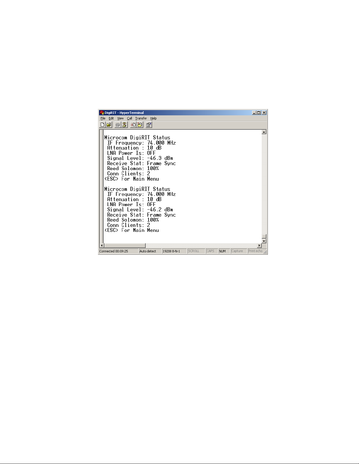
Release 1 DAMS-NT DigiRIT Operation Manual 12/14/2012
menu system provides additional system information and the ability to configure the unit for
operation.
3.2.1. Test Port Status Report
Generally, when a PC is first connected to the Test Port, the unit will be in the status report loop.
Figure 16 shows and an example of the status report captured using HyperTerminal. Comparing
this screen shot to the Status Screen example of Figure 7, one can readily correlate the various
pieces of status information.
Figure 16: Test Port Status Loop
3.2.2. Serial Test Port Menu System
As Figure 16 indicates, pressing the ESC key when the status loop is active will call up the Test
Port’s “Main Menu”. The DigiRIT Main Menu is shown in Figure 17 and consists of three
options:
• I System Info
• S System Setup Menu
• V Virtual Channel Setup Menu
The System Info option is also shown in Figure 17 and simply provides a way to get the unit’s
serial number, and the respective firmware version numbers of the two embedded processor, the
Main and the Slave. As Figure 17 also indicates, this information is accessed by entering ‘I’ at
the Main Menu “Selection:” prompt.
While all menu options are displayed in upper case, the DigiRIT menu system is not case
sensitive, i.e. the menu options can be selected using lower case letters. Generally speaking,
pressing the ESC key at any menu will exit the current menu and return to the parent. For
example; pressing ESC with the System Information displayed, will return to the Main Menu.
Microcom Design, Inc. 28
Page 30
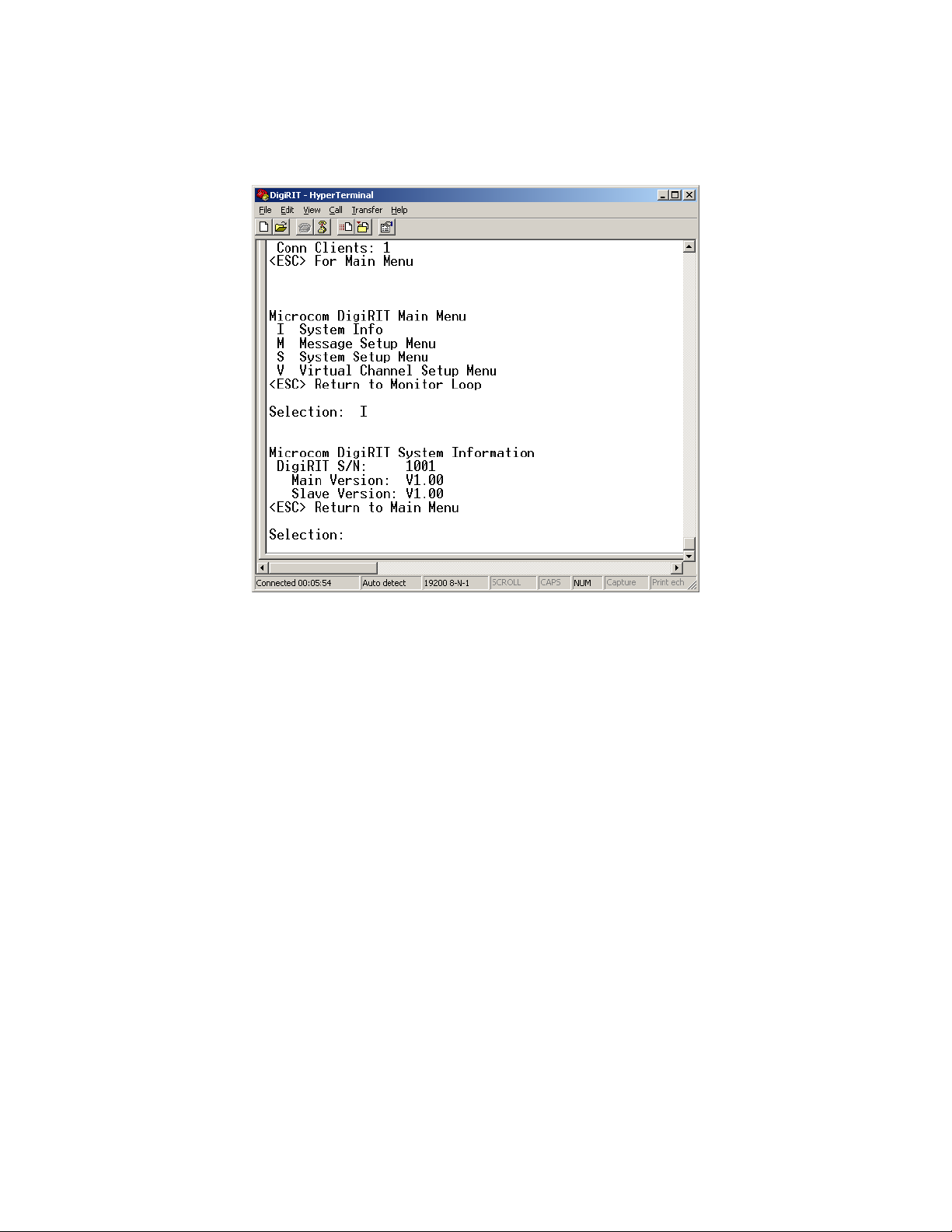
Release 1 DAMS-NT DigiRIT Operation Manual 12/14/2012
However, for the configuration menus discussed in Sections 3.2.2.1 and 3.2.2.2, pressing ESC
also abandons any edits and exits the menu. Further, pressing ESC at the Main Menu returns the
unit to status monitor loop.
Figure 17: Test Port Main Menu and System Information
3.2.2.1. System Setup Menu
Pressing ‘S’ at the Main Menu prompt calls up the System Setup menu as shown in Figure 18.
The options available here correlate to those covered in Sections 3.1.1 through 3.1.4 in the
pushbutton Setup mode. However, in the Test Port System Setup Menu, the operator alters these
settings by entering the appropriate menu option following by an equals followed by the new
setting at the selection prompt.
One other somewhat obvious distinction between the menu approach versus the pushbutton setup
is that the current values for the related entries are all visible in the menu system. As noted in
Section 3.1.1, separate values are kept for the IF related settings based on the IF Input. As the
example of Figure 18 indicates, selecting the alternate IF Input calls up its related values.
Altering the setting for the 70 MHz parameters does not affect the 140 MHz IF Input values, and
vice versa.
Once the desired IF Input is selected and any necessary changes to the other parameters are
made, entering ‘S’ at the System Setup menu will “Save & Apply” the changes forcing the unit
to re-configure itself accordingly. Note that pressing ‘S’ does not exit the System Setup menu.
As indicated, pressing ESC will abandon any changes made since the last save operation and exit
the System Setup menu. If no changes have been made since the last “Save & Apply” operation,
the DigiRIT will simply exit this menu and return to the Main Menu.
Microcom Design, Inc. 29
Page 31
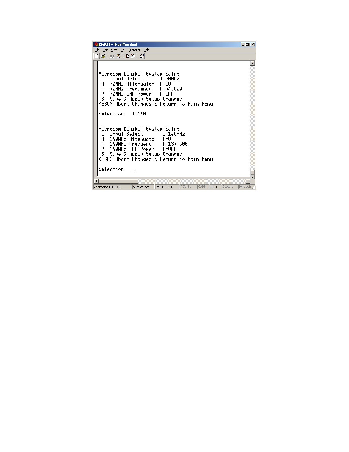
Release 1 DAMS-NT DigiRIT Operation Manual 12/14/2012
Figure 18: System Setup Menu
3.2.2.2. Virtual Channel Setup Menu
Pressing ‘V’ at the Main Menu prompt calls up the Virtual Channel Setup menu as shown in
Figure 19. The options available here correlate to those covered in Section 3.1.5 in the
pushbutton Setup mode. However, in the Test Port System Setup Menu, the operator alters these
settings by entering the appropriate menu option following by an equals followed by the new
comma separated values. Like the System Setup menu, the current values for the Virtual
Channel Setup are displayed as part of the menu information and serves as a format guide when
making changes.
As with the pushbutton setup, this menu lets the user define up to four LRIT Virtual Channels to
monitor for DCS traffic, a value of 63 indicates an unused channel. For each of the defined
channels, the operator can allocate a percentage portion of DigiRIT’s DCS message buffer to that
channel based on the expected traffic. When altering these values, the same validation rules
defined in Section 3.1.5 are applied.
As was the case with the System Setup menu, the ‘S’ menu option saves and applies any
changes. Likewise, ESC exits the menu, abandoning any changes made since the last save
operation.
Microcom Design, Inc. 30
Page 32
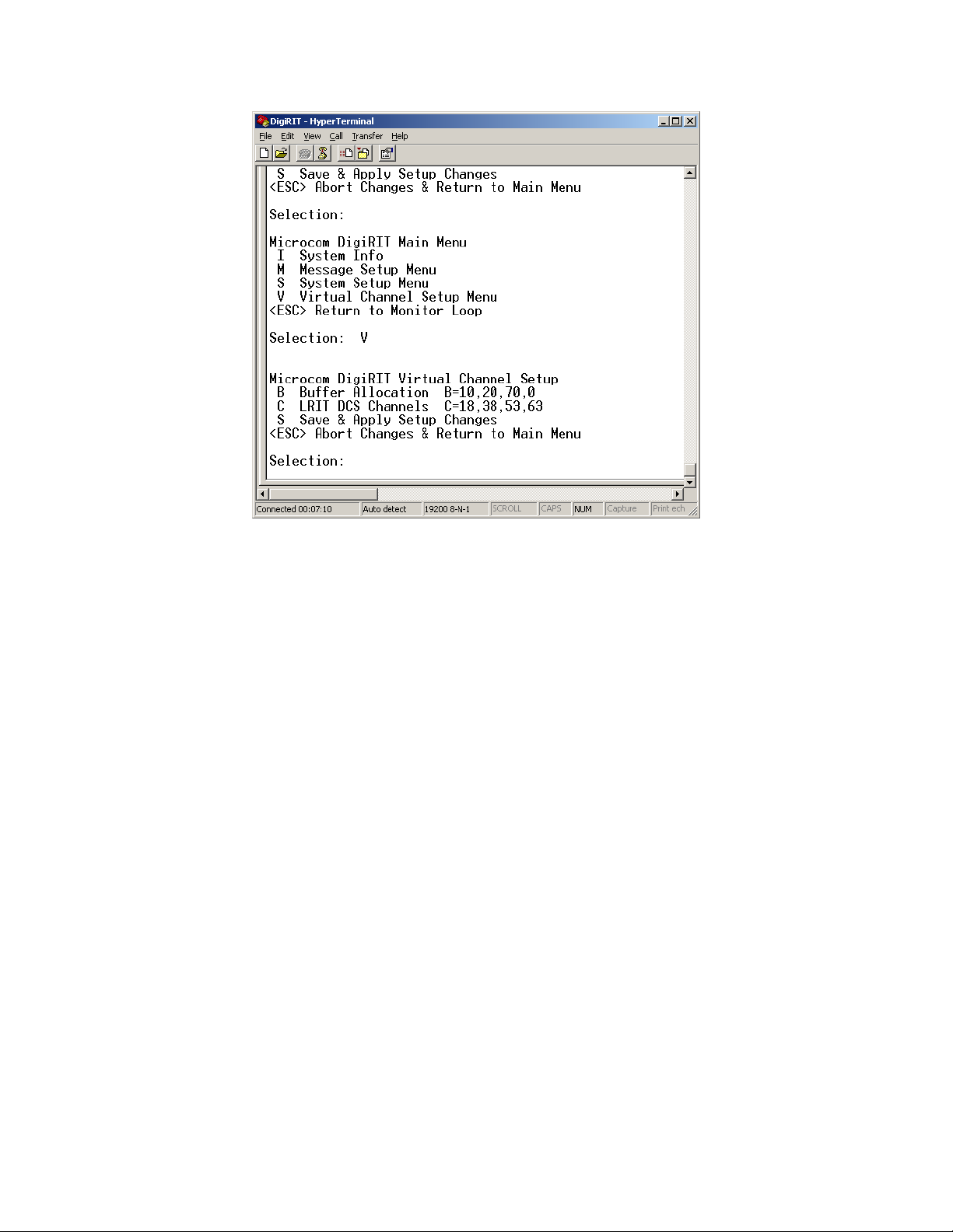
Release 1 DAMS-NT DigiRIT Operation Manual 12/14/2012
Figure 19: Virtual Channel Setup Menu
3.2.2.3. Message Setup Menu
Two settings that can only be configured via the terminal interface are related to the DAMS-NT
message interface (see Section 1.3.2). These options are accessed through the Message Setup
menu as shown in Figure 20. The first option determines how messages received without a Baud
rate specifier are handled, while the second option determines the utilization of the Slot Number
field in the DAMS-NT header (see Section 1.3.2.1).
3.2.2.3.1. Unknown Baud Rate Option
While most DCS messages received in the LRIT stream have the Baud rate specified, some do
not. The messages that do not specify the Baud rate are typically DCS informational messages;
since these messages are system generated and not actual DCP transmitted messages, the Baud
rate is not truly applicable.
The DigiRIT can handle messages without the Baud specified in one of two ways. First, the
DigiRIT can simply parrot this fact by reporting the DAMS-NT Baud field as ‘0000’, indicating
the Baud is “unknown” or “undefined”. However, some DAMS-NT Clients will not accept this
value and will report an error if the Baud rate is not one of the three active DCS message baud
rates; i.e. ‘0100’, ’0300’, or ‘1200’. As such, the DigiRIT also includes an option to report the
Baud rate as the most common value of ‘0300’ if the actual Baud rate is not present in the LRIT
data.
If the “Allow Unknown Baud” option is enabled or set to “ENB”, the DigiRIT will report a
‘0000’ in the DAMS-NT header (see Section 1.3.2.1) for messages received without the baud
rate specified. The default setting is disabled or “DIS”, in which case the DigiRIT will report
‘0300’ in the DAMS-NT header when the Baud rate is unknown. To change this setting, the user
must access the Message Setup menu and at the selection prompt type “B=xxx”, where “xxx” is
Microcom Design, Inc. 31
Page 33
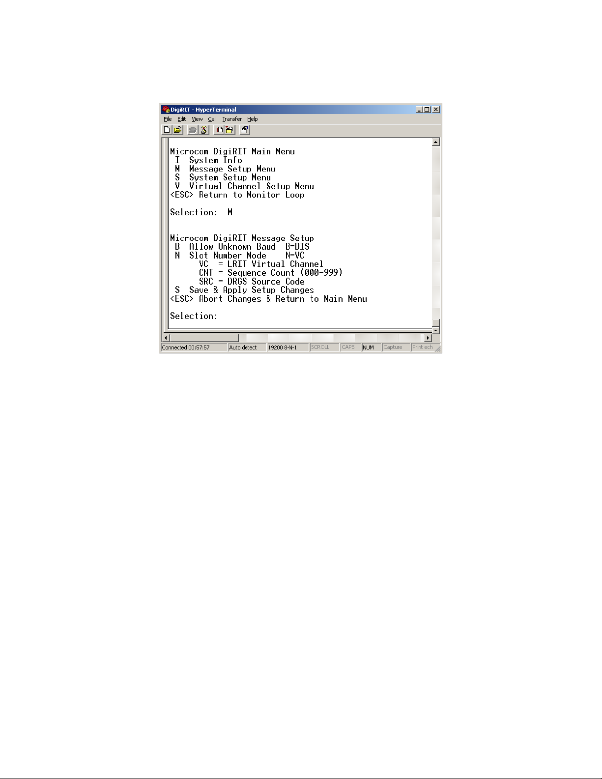
Release 1 DAMS-NT DigiRIT Operation Manual 12/14/2012
either “DIS” or “ENB”. Alternately, in place of these 3-character strings, the user can simply
type just the first letter, “D” or “E”.
Figure 20: Message Setup Menu
3.2.2.3.2. Slot Number Mode Option
The second option available in the Message Setup menu is the “Slot Number Mode”. The
default setting for the DigiRIT is to use the LRIT Virtual Channel for the Slot Number in the
DAMS-NT header as explained in Section 1.3.2.1. Alternately, the user can specify to have the
DigiRIT use the Slot Number as a sequence counter, or to use it to report a code value indicating
the DRGS source of the message.
In the “Sequence Count” or “CNT” option, the Slot Number in the DAMS-NT header is used as
a sequence counter. The first message received and reported has a Slot Number value of ‘000’,
and subsequent messages have the Slot Number incremented by one. Once the message count
reaches ‘999’ it will rollover back to ‘000’. While not recommended for operational use, this
mode can be useful for test purposes to verify all received messages are being reported and
captured via the DAMS-NT interface since the LRIT DCS transmission does not currently
include a message sequence number as is the case with DOMSAT rebroadcast.
The “DRGS Source Code” option allows the Slot Number to be used to identify the receive site
that the DCS message was originally received at. The LRIT DCS message format includes the
same two-character DRGS source as is utilized in the DCS LRGS network. However, the
DAMS-NT format does not allow use of this code. Configuring the DigiRIT to the “DRGS
Source Code” or “SRC” option for the “Slot Number Mode” allows the source of the message to
be reported in the Slot Number field of the DAMS-NT header according to the mapping defined
in Table 3. These mappings cover the three major receive sites and also several medium size
DRGS systems. As Table 3 indicates, if the DRGS sourcing the message is not known or cannot
be identified in the LRIT stream, then the Slot Number will be reported as ‘999’.
Microcom Design, Inc. 32
Page 34

Release 1 DAMS-NT DigiRIT Operation Manual 12/14/2012
To change “Slot Number Mode”, the user enters “N=” followed by one of the three mode
keywords (“VC”, “CNT”, or “SRC”) at the selection prompt. As with the “Allow baud
Unknown” option, these keywords can be alternately abbreviated to just the first letter.
Once the Message Setup options are adjusted to the desired settings, the “Save & Apply
Changes” menu item must be utilized to store the new settings and re-configure the DigiRIT
accordingly; similar to the “System Setup” and “Virtual Channel Setup”.
Table 3: DRGS Source Code to Slot Number
DRGS
Code
UP 001 NOAA WCDA Primary E/W – Wallops Island, VA
UB 002 NOAA WCDA Backup E/W – Wallops Island, VA
NP 011 NOAA NSOF Primary E/W – Suitland, MD
NB 012 NOAA NSOF Backup E/W – Suitland, MD
XE 021 USGS EROS East – Sioux Falls, SD
XW 022 USGS EROS West – Sioux Falls, SD
RE 031 USACE MVR East – Rock Island, IL
RW 032 USACE MVR West – Rock Island, IL
d1 051 NIFC West Unit 1 – Boise, ID
d2 052 NIFC West Unit 2 – Boise, ID
LE 061 USACE LRD East – Cincinnati, OH
SF 071 SFWMD East – West Palm Beach, FL
OW 081 USACE NWO – Omaha, NE
999 Unknown DRGS Source Code
3.3. Network Interface Configuration
The DigiRIT Receiver provides two TCP/IP network interfaces, the DCS Message and LRIT
sockets, as discussed in Sections 1.3.2 and 1.3.3, respectively. The default IP Address for the
DCS Message socket is 192.168.54.101, and the default IP Address for the LRIT socket is
192.168.54.102. Both sockets have a default Port number of 4001. While these settings should
be adequate for most installations, the IP Addresses and Port numbers can be can be changed if
necessary.
Slot
Number
Source Description
To provide these network interfaces, the DigiRIT utilizes a serial-to-Ethernet module (P/N
MiiNePort E2) manufactured by Moxa Inc (www.moxa.com). The Moxa module includes a
Web Console that can be accessed from any web browser application; such as Microsoft Internet
Explorer or Mozilla Firefox.
To access the Moxa Web Console simply launch the preferred web browser and enter the current
IP Address of the interface that needs to be changed. As shown in Figure 21, the Web Console
will come up in the “Overview” screen. This screen provides several useful pieces of
information including the Model and Serial Number of the module, the current Firmware version
(of the Moxa module, not the DigiRIT) and the unique MAC Address of the Moxa module.
Microcom Design, Inc. 33
Page 35
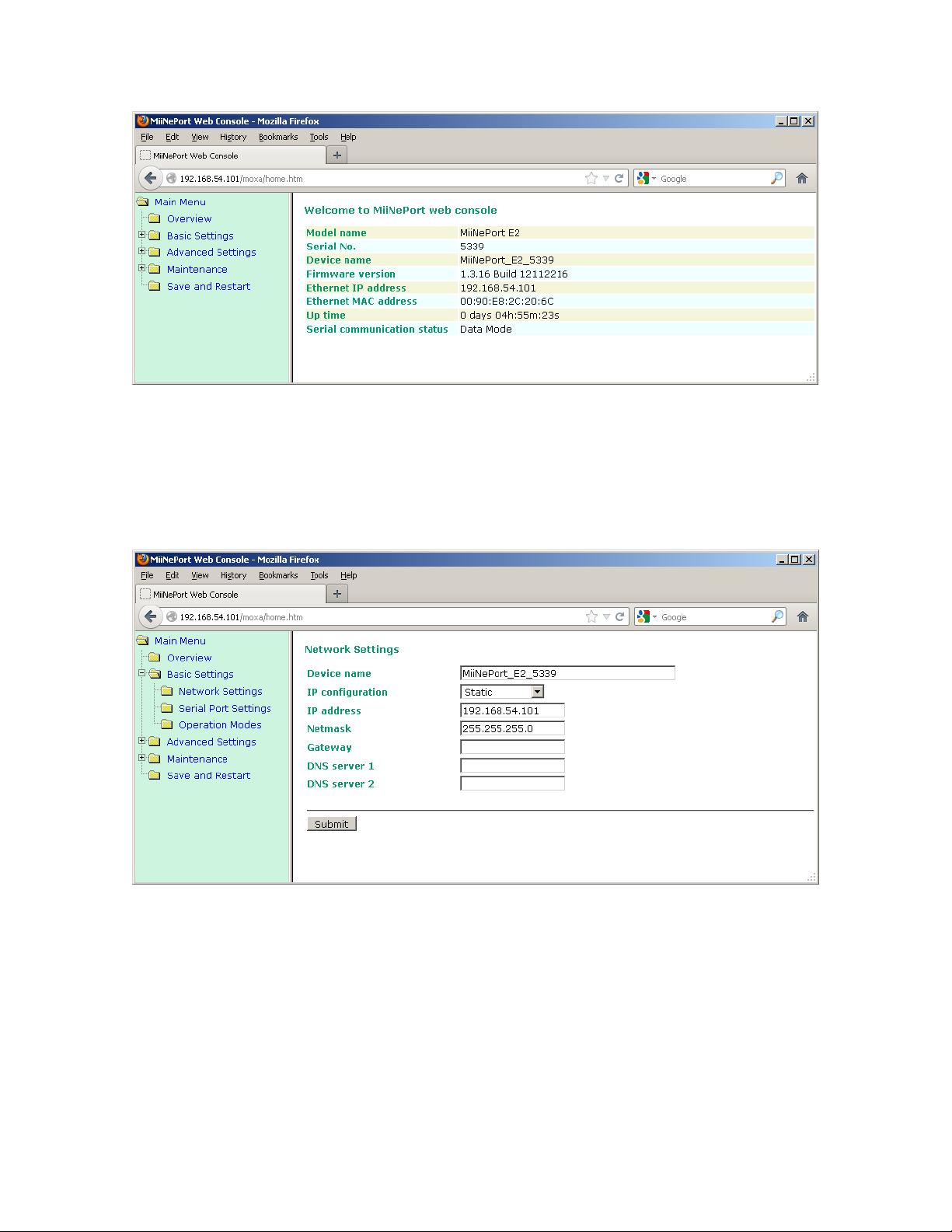
Release 1 DAMS-NT DigiRIT Operation Manual 12/14/2012
Figure 21: MiiNePort Web Console – Overview Screen
To change the IP Address of the module and hence the associated TCP/IP interface, expand the
“Basic Settings” folder and select the “Network Settings” option folder shown on the left side of
the web console browser. This will display the “Network Settings” page as shown in Figure 22.
To change the IP address of the unit, simply enter the new address in the corresponding edit box
and click the “Submit” button.
Figure 22: Web Console – Network Settings
Before applying the changes, the Web Console will display the warning shown below and ask for
confirmation. To commit the changes, click the “Save/Restart” button shown in Figure 23.
However, if additional changes need to be made, click the “Back” button or simply select the
folder with the parameter that needs to be altered. For example, to change the Port for the
interface, select the “Operation Modes” option and the settings within this group will be
displayed as shown in Figure 24.
Microcom Design, Inc. 34
Page 36
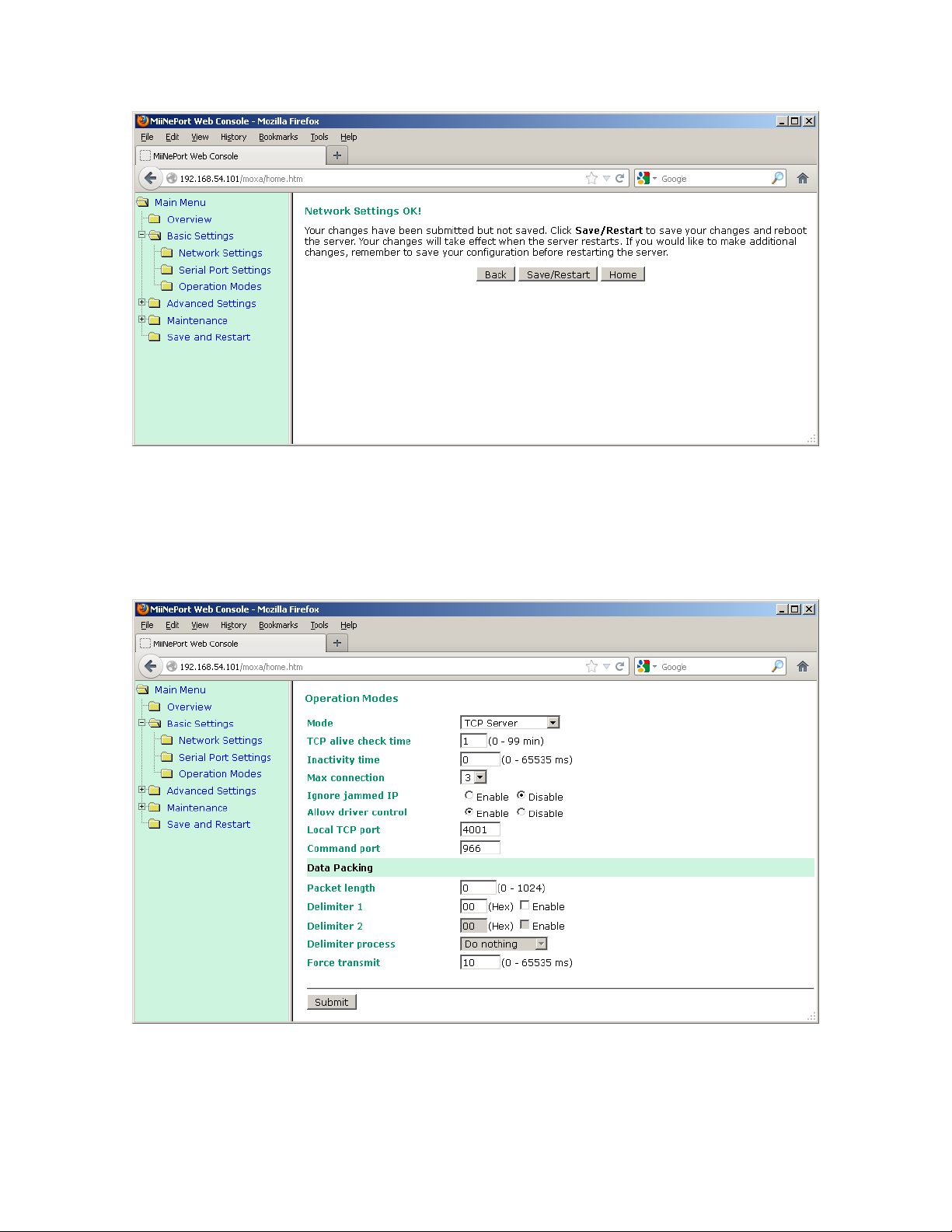
Release 1 DAMS-NT DigiRIT Operation Manual 12/14/2012
Figure 23: Web Console – Save/Restart
The interface Port number is the field designated “Local TCP Port”. When changing this value,
be careful not to alter any other settings. Incorrectly, altering some of these fields can adversely
affect the operation of the DigiRIT Receiver. Once the Port number field has been altered, once
again click the “Submit” button to lock it in, but not apply the change.
Figure 24: Web Console – Operation Modes Settings
As is readily apparent from the screen shots shown so far, the Moxa MiiNePort E2 module has
numerous optional settings. While some of these cannot be altered, as noted above, others can
Microcom Design, Inc. 35
Page 37
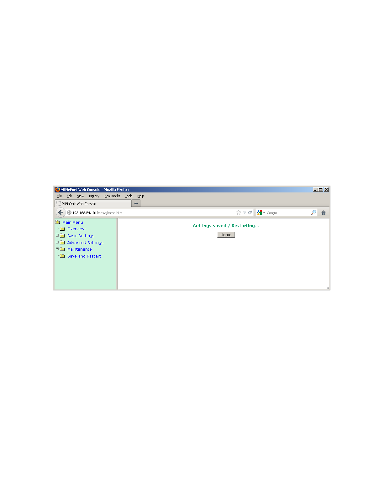
Release 1 DAMS-NT DigiRIT Operation Manual 12/14/2012
be freely altered and may prove useful to some users for a variety of purposes. For example, in
the “Advanced Settings” is an option to define an “Accessible IP List”, which can be used to
limit the specific Clients that can connect to the DigiRIT.
A complete discussion of the available options is beyond the scope of this manual, but can be
found in the “MiiNePort E2/E3 User’s Manual” that is available on the Moxa website. Also
available in the Moxa website is the “NPort Search Utility” application that can locate any and
all Moxa modules on a network without having to know the configured IP Addresses of the
modules; a useful feature if the IP Address is incorrectly altered and/or the IP Address is
unknown.
Once all desired changes have been made and the last alteration submitted, the “Save/Restart”
button must be clicked to apply all the previously submitted changes. When this happens the
Web Console will display the acknowledgement message shown in Figure 25. If the IP Address
is altered, the new address must be entered into the web browser to re-access the module via the
Web Console. Naturally, any Clients that had previously connected to the changed DigiRIT
socket must also be updated accordingly.
Figure 25: Web Console – Settings Saved
Microcom Design, Inc. 36
Page 38

Release 1 DAMS-NT DigiRIT Operation Manual 12/14/2012
APPENDIX A: Acronyms and Abbreviations
8PSK 8 State Phase Shift Keying
AC Alternating Current
AGC Automatic Gain Control
AM Amplitude Modulation
ANSI American National Standards Institute
ARM Abnormal Response Messages
ASCII American Standard Code for Information Interchange
BCH Bose, Chaudhari and Hocquenghem
BER Bit Error Rate, Bit Errors Received
bps, BPS Bits per Second
BPSK Binary Phase Shift Keying
CDA Command and Data Acquisition
CGMS Coordination Group for Meteorological Satellites
DADDS DCS Administrative and Data Distribution System
DAMS-NT Data Acquisition and Monitoring System – New Technology
DAPS Data Collection System Automated Processing System
dB Decibel
dBm Decibels relative to one milliwatt
DC Direct Current
DCP Data Collection Platform
DCPRS Data Collection Platform Radio Set
DCS Data Collection System
Demod Demodulator
DOMSAT Domestic Satellite
DPCM Dual Pilot Control Module
DRGS Direct Readout Ground Station
DSP Digital Signal Processor; Digital Signal Processing
EIRP Equivalent Isotropic Radiated Power
EOT, ETX End of Transmission
FSS Frame Synch Sequence
GOES Geostationary Operational Environmental Satellite
GUI Graphical User Interface
HRIT High Rate Information Transmission
Hz Hertz
Microcom Design, Inc. 37
Page 39

Release 1 DAMS-NT DigiRIT Operation Manual 12/14/2012
ICD Interface Control Document
I/O Input/Output
IF Intermediate Frequency
IIM Input Interface Module (DAMS-NT)
IP Internet Protocol
IRIG-B Inter-Range Instrumentation Group code B for 1 second timing standard
kHz Kilohertz
L-band 1694.3 to 1694.7 MHz for this DCS application
LAN Local Area Network
LRGS Local Readout Ground Station
LRIT Low Rate Information Transmission
LSB Least Significant Bit
max Maximum
MHz Megahertz
min Minimum
MSB Most Significant Bit
NESDIS National Environmental Satellite, Data, and Information Service
NIC Network Interface Controller or Network Interface Card
NIC-MUX Network Interface Controller and Multiplexer (DAMS-NT)
NOAA National Oceanic and Atmospheric Administration
NRZ-L Non-Return to Zero - Level
NSOF NOAA’s Satellite Operations Facility
NWS National Weather Service
NWSTG National Weather Service Telecommunications Gateway
O&M Operations and Maintenance
OEM Original Equipment Manufacturer
OS Operating System
PM Phase Modulation
ppm, PPM parts per million
PSK Phase Shift Keying
QMB Quad Mother Board (DAMS-NT)
RF Radio Frequency
sps Symbols per Second
sync Synchronizer; Synchronization
Microcom Design, Inc. 38
Page 40

Release 1 DAMS-NT DigiRIT Operation Manual 12/14/2012
TCP Transfer Control Protocol
U.S. United States
UHF Ultra High Frequency (401.7 to 402.1 MHz for this DCS application)
UTC
V Volts
VC Virtual Channel
Vpp Volts peak-to-peak
WCDA Wallops Command and Data Acquisition
WCDAS Wallops Command and Data Acquisition Station
Microcom Design, Inc. 39
 Loading...