

Page 1

MODEL 485TC
DIRECT THERMAL PRINTER
OPERATOR’S MANUAL
PART NUMBER: 880058-0100
January 3, 2018 CPC
Copyright © 2018 by Microcom Corporation, Lewis Center, Ohio – All rights reserved.
Printed in the United States of America
Page 2

Page 3

Proprietary Statement
This manual contains information proprietary to Microcom Corporation. This information is
intended solely for the use of parties operating and maintaining such equipment described
herein.
Product Enhancements
Microcom Corporation is committed to the continual improvement of performance and
quality in our products. For this reason, specifications are subject to change without notice.
Liability Disclaimer
Microcom Corporation makes every effort to assure that all information and specifications
contained in this manual are accurate; however, mistakes are sometimes made. Microcom
Corporation shall not be liable for any damages resulting in the use or misuse of this
product. The exclusion or limitation involving consequential or incidental damage does not
apply to all states; therefore limitation mentioned above may or may not apply.
FCC Compliance Statement
This equipment has been tested and found to comply with the limits for a Class A digital
device, pursuant to Part 15 of the FCC rules. These limits are designed to provide
reasonable protection against harmful interference when the equipment is operated in a
commercial environment. This equipment generates, uses, and can radiate radio frequency
energy, and if not installed and used in accordance with the instructions contained in this
manual, may cause harmful interference to radio communications.
Products and company names mentioned herein may be trademarks of their respective
owners.
Page 4

Page 5

Table of Contents
INTRODUCTION ............................................................................................. V
CHAPTER 1: PRINTER SPECIFICATIONS 1-1
1.1 General Specifications 1-1
1.2 Printing Specifications 1-1
1.3 Media Specifications 1-2
CHAPTER 2: FEATURES AND OPTIONS 2-1
2.1 Fonts 2-1
2.2 Graphics 2-1
2.3 Bar codes 2-1
2.4 Special Features 2-2
2.5 Options 2-2
CHAPTER 3: GETTING STARTED 3-1
3.1 Unpacking and Inspection 3-1
3.2 Printer Power 3-2
3.3 RS232 Serial Communication Interface 3-2
3.3.1 RS-232 Serial Cables ................................................................................... 3-3
3.3.2 RS-232 Serial RJ-12 ..................................................................................... 3-3
3.4 USB Communication Interface 3-4
3.5 Host USB Interface 3-4
3.6 Ethernet Communication Interface 3-4
3.7 Cash Drawer Option 3-4
3.7.1 Cash Drawer RJ12 Adapter Option ............................................................... 3-5
3.8 AUX Option 3-5
3.9 Loading Media 3-6
3.10 Print Button and Status Indicator Light 3-7
3.10.1 Print Button ................................................................................................... 3-7
3.10.2 Status Indicator Light .................................................................................... 3-8
3.11 Printer Modes 3-8
3.11.1 Ready Mode: GREEN .................................................................................. 3-8
3.11.2 Halted Mode: RED ................................................................ ....................... 3-8
3.11.3 Diagnostic Mode ........................................................................................... 3-9
3.11.3.1 Entering Diagnostic Mode ......................................................................... 3-9
3.11.3.2 Statistics Label .......................................................................................... 3-9
3.11.3.3 Test Ticket ............................................................................................... 3-10
3.12 TOF Sensor 3-10
3.13 Media Roll Holder Option 3-12
3.14 Ticket Catch Tray Option 3-12
3.15 Wristband Media Adapter Option 3-13
3.16 Qualsoft Windows Driver 3-14
3.16.1 Installing the Windows Driver ...................................................................... 3-14
3.16.2 Configuring the Driver ................................................................................. 3-18
3.16.3 Printer Properties Page - General tab ......................................................... 3-19
485TC Operator’s Manual - 880058-0100 i
Page 6

3.16.4 Printer Properties Page - Ports tab ............................................................. 3-20
3.16.5 Printing Preferences - About tab ................................................................. 3-21
3.16.6 Printing Preferences - Print tab ................................................................... 3-21
3.16.6.1 Print tab - Advanced ................................................................................ 3-22
3.16.7 Print tab - Halftone Adjustment ................................................................... 3-22
3.16.8 Print tab - Halftone Properties ..................................................................... 3-23
3.16.9 Print tab - User Commands ......................................................................... 3-23
3.16.10 Printing Preferences - Paper tab ................................................................. 3-24
3.16.10.1 Paper tab - Rotation ............................................................................. 3-24
3.16.10.2 Paper tab - Units .................................................................................. 3-24
3.16.10.3 Paper tab - Page Sizes ........................................................................ 3-24
3.16.10.4 Paper tab - Mirror ................................................................................. 3-24
3.16.10.5 Paper tab - Default ............................................................................... 3-25
3.16.11 Printing Preferences - Media tab ................................................................. 3-25
3.16.11.1 Media tab - Settings ............................................................................. 3-25
3.16.11.2 Media tab - Feed Options ..................................................................... 3-26
3.16.12 Printing Preferences - Presenter tab ........................................................... 3-27
3.16.12.1 Presenter tab - Configuration ............................................................... 3-28
3.16.12.2 Configuration - Modes .......................................................................... 3-28
3.16.12.3 Configuration - Advanced ..................................................................... 3-29
3.16.13 Printing Preferences - Modification tab ....................................................... 3-29
3.16.13.1 Modification - No of Labels ................................................................... 3-29
3.16.13.2 Modification - Print Speed (inch/s) ....................................................... 3-29
3.16.13.3 Modification - Disable Status ................................................................ 3-29
3.16.14 Printing Preferences - Save/Restore tab ..................................................... 3-31
3.16.14.1 Save/Restore - Restore settings from file… ......................................... 3-31
3.16.14.2 Save/Restore - Save settings to file….................................................. 3-31
3.16.14.3 Save/Restore - Restore factory defaults… ........................................... 3-31
3.16.15 Status Messages ......................................................................................... 3-31
3.16.15.1 PRINTER_STATUS_WAITING ............................................................ 3-32
3.16.15.2 PRINTER_STATUS_BUSY ................................................................. 3-32
3.16.15.3 PRINTER_STATUS_PAPER_OUT...................................................... 3-32
3.16.15.4 PRINTER_STATUS_PAPER_JAM ...................................................... 3-32
3.16.15.5 PRINTER_STATUS_PAPER_PROBLEM ............................................ 3-32
3.16.15.6 PRINTER_STATUS_USER_INTERVENTIO N .................................... 3-32
3.16.15.7 PRINTER_STATUS_OFFLINE ............................................................ 3-32
3.16.15.8 PRINTER_STATUS_OUTPUT_BIN_FULL .......................................... 3-32
3.16.15.9 PRINTER_STATUS_DOOR_OPEN .................................................... 3-32
3.16.15.10 PRINTER_STATUS_IO_ACTIVE ........................................................ 3-32
3.17 Configuration Application 3-33
3.17.1 Selecting a Device ...................................................................................... 3-33
3.17.1.1 Configuration Application - Serial (USB / RS-232) ................................... 3-33
3.17.1.2 Configuration Application - USB HID ....................................................... 3-34
3.17.1.3 Configuration Application - Ethernet ........................................................ 3-34
3.17.2 Configuring a device ................................................................................... 3-34
3.17.2.1 Applying changes .................................................................................... 3-35
3.17.2.2 Reverting changes ................................................................................... 3-35
3.17.2.3 Saving/loading configuration files ............................................................ 3-35
3.17.3 Application preferences ............................................................................... 3-35
ii 485TC Operator’s Manual - 880058-0100
Page 7

CHAPTER 4 PRINTER MAINTENANCE 4-1
4.1 Maintenance Schedule 4-1
4.2 Thermal Printer Cleaning Card 4-1
4.3 Internal Cleaning 4-3
4.4 Print Head Maintenance 4-4
4.5 Replacing the Drive Roller 4-5
4.6 Adjusting Printhead Pressure 4-7
CHAPTER 5: TROUBLESHOOTING 5-1
5.1 Troubleshooting Tips 5-1
INDEX 6-1
General Index 6-1
List of Figures 6-5
List of Tables 6-7
APPENDIX 7-1
Appendix A: Limited Warranty 7-1
Appendix B: RMA Procedure 7-3
Glossary 7-5
Appendix C: User Notes 7-9
485TC Operator’s Manual - 880058-0100 iii
Page 8

iv 485TC Operator’s Manual - 880058-0100
Page 9
Introduction
The Model 485TC printer has been designed to provide solutions for the ticketing industry.
The printer uses the same reliable print mechanism found in the Model 428TM and 438TM
printers. The print mechanism has been designed with a 4” printhead capable of printing up
to 8” per second and is available in 203 or 300 dpi. The printer may be used as a graphics
printer or as an FGL emulation printer.
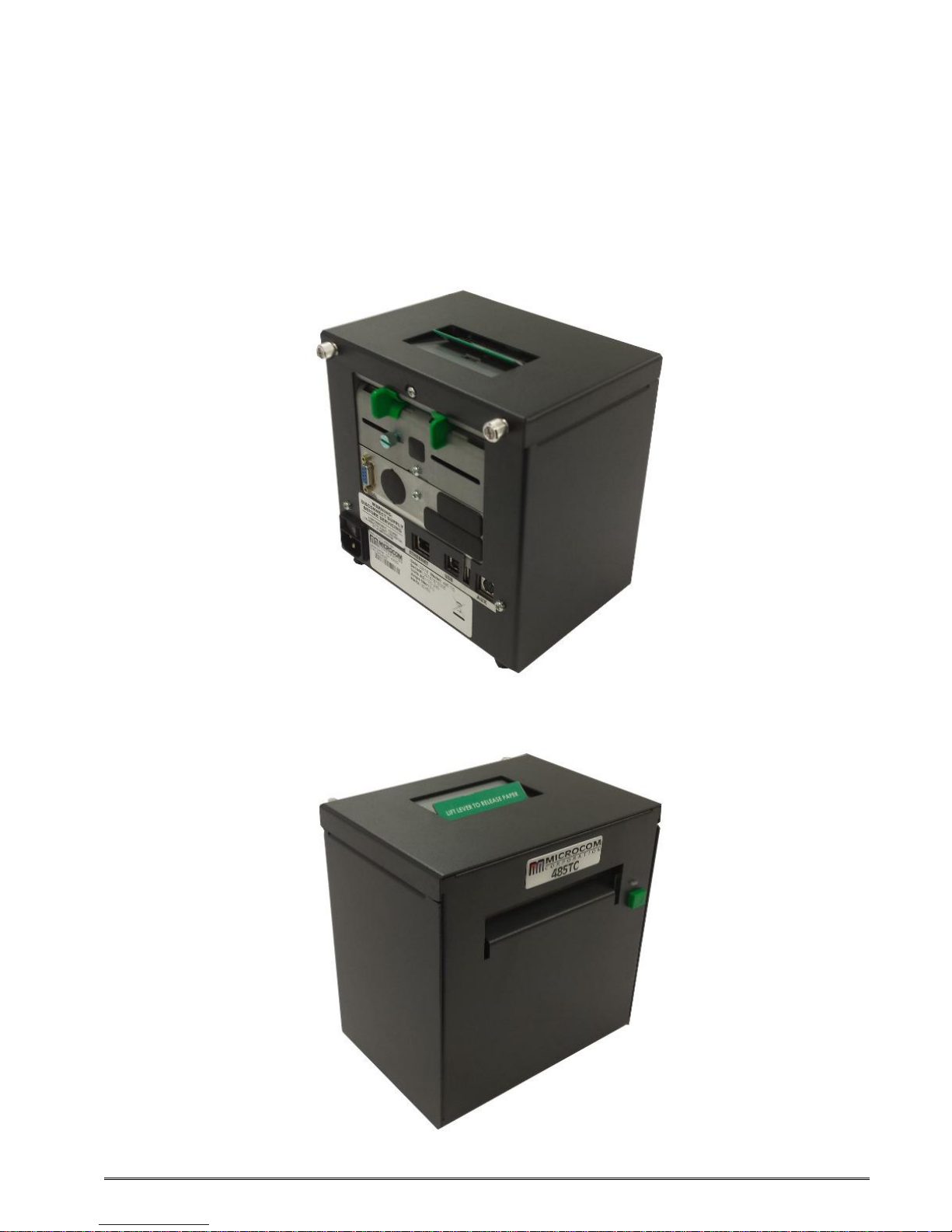
485TC Rear Side View
485TC Front Side View
485TC Operator’s Manual - 880058-0100 v
Page 10

vi 485TC Operator’s Manual - 880058-0100
Page 11

Chapter 1: Printer Specifications
1.1 General Specifications
Width* 7.3” (185 mm)
Height* 7.4” (188 mm)
Depth* 5.8” (148 mm)
Weight* 10.2 lbs. (4.6 kg)
Electrical +24 VDC
Current 3.5 Amps maximum
Temperature 40° F – 104° F (5° C – 40° C), operating
Humidity 10% – 85%, non-condensing
RAM Memory 256 Mb
Flash Memory 512 Mb
Agency Approvals RoHS, FCC Class A, cTUVus
Interface Communications RS232, USB, and Ethernet Ports
Flow Control CTS/RTS Hardware
Baud Rate Up to 115200
Parity Odd, Even, and None
Data Bits 7 or 8
Table 1-1 General Specifications
* NOTE: Listed specifications are based on a standard print mechanism and may vary
based on final configuration.
1.2 Printing Specifications
Print Type Direct Thermal
Print Resolution
Maximum Print Speed Up to 10”/sec. (250 mm/sec.)
Maximum Print Width
Maximum Print Length 26” (660 mm)
Minimum Print Length 0.25” (6 mm)
Table 1-2 Printing Specifications
203 DPI (8 dots/mm = 0.0049” per dot)
300 DPI (12 dots/mm = 0.0032” per dot)
203 DPI = 4.098” (104.10mm); 832 dots
300 DPI = 4.252” (108 mm); 1,280 dots
485TC Operator’s Manual - 880058-0100 1-1
Page 12

Printer Specifications Chapter 1
1.3 Media Specifications
Media Types
Maximum Media Thickness* .011” (.28 mm)
Maximum Media Width
Continuous, die-cut, preprinted and tag stock either rolled
or fanfold
4.375” (111 mm)
*NOTE: The printers may print on thicker media types depending on the pliability of the
material; however, this requires testing and evaluation. Contact your authorized Microcom
Corporation representative for additional information regarding testing and evaluation of
thicker or rigid media types.
Table 1-3 Media Specifications
1-2 485TC Operator’s Manual - 880058-0100
Page 13

2.1 Fonts
· 16 resident bitmapped alpha-numeric fonts.
· Downloadable scalable fonts.
· All bitmapped fonts expandable in height and width.
· Reverse image printing.
· Rotated: 0 º, 90 º, 180 º, and 270 º.
2.2 Graphics
· Resident Lines feature.
· Storage of fonts, label formats and graphics in both volatile RAM and non-
volatile FLASH memory.
· Rotated: 0 º, 90 º, 180 º, and 270 º.
2.3 Bar codes
Chapter 2: Features and Options
· One-dimensional
· Code 39
· Interleaved 2 of 5
· Code 128 (A, B, C and
Auto)
· Code 93
· Codabar
· Modified Plessey
· UPC-A
· UPC-E
· EAN 8
· EAN 13
· UCC/EAN 128
· Postnet.
· Planet Code
· Two-dimensional
· GS1 Databar
Omni Directional
Truncated
Stacked
Stacked Omni-
directional
Limited
Expanded
· PDF-417
· Maxi code
· GS1 Data matrix
· Aztec
· Softstrip
· QR Code
· Rotated: 0 º, 90 º, 180 º, and
270 º.
· Expandable in height and
width.
485TC Operator’s Manual - 880058-0100 2-1
Page 14

Features and Options Chapter 2
2.4 Special Features
· Easy print head cleaning
· Tool less platen roller replacement
· Adjustable media guides for easy label centering
· Automatically adjustable reflective blackline sensor in media guide
· Software controlled contrast adjustment
· Detects label gap, black line, and blow-hole using reflective and
transmissive sensors
· Internal statistical counters for inches and labels printed
· Remote printer interrogation
· On-site programmable flash memory updates
· Autoload / Alignment of media
2.5 Options
· +24 VDC Universal 100W Desktop Power Supply
· 300 dpi print head
· Heavy Duty Rotary Cutter
· Ethernet Port
· Pre-Stock Out Sensor Assembly
· Low Paper Sensor Assembly
· Wristband Option
· Paper Supply Holders
· Media Catch Trays
· Cleaning kit
2-2 485TC Operator’s Manual - 880058-0100
Page 15
Chapter 3: Getting Started
3.1 Unpacking and Inspection
The printer has been packaged in protective foam to help reduce the damage during
shipment.
Inspect the shipping container(s) for signs of damage. If damage is evident, contact the
shipping company immediately to file a damage claim.
After the printer is removed from the container(s), verify that all the items on the packing list
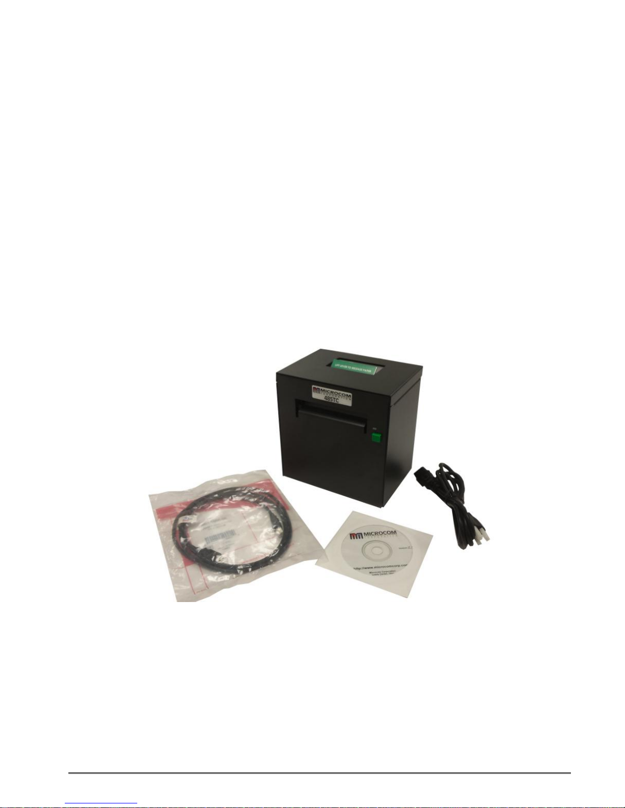
are present and in good condition. The picture below (See Figure 3-1) shows a 438TC and
optional power cord. Your shipment may contain different items.
The foam and shipping container(s) should be kept and used if the printer is to be shipped
at a later time. Additional shipping materials can be ordered by contacting the Microcom
Corporation Service Department.
Figure 3-1 Typical Printer Accessories
485TC Operator’s Manual - 880058-0100 3-1
Page 16

Getting Started Chapter 3
RS232 Port
USB Port
Ethernet Port
ON/OFF Switch
Power
Connection
Figure 3-2 Printer Rear Panel
External Media
Entry Slot
Optional Rj12
Serial
Optional Cash
Drawer Port
AUX Port
Host USB Port
3.2 Printer Power
The printer has a universal auto-sensing internal power supply that operates in the 100-240
VAC; 50-60 Hertz range. The three-prong female end of the power cord plugs into the
mating connector located on the back of the printer.
3.3 RS232 Serial Communication Interface
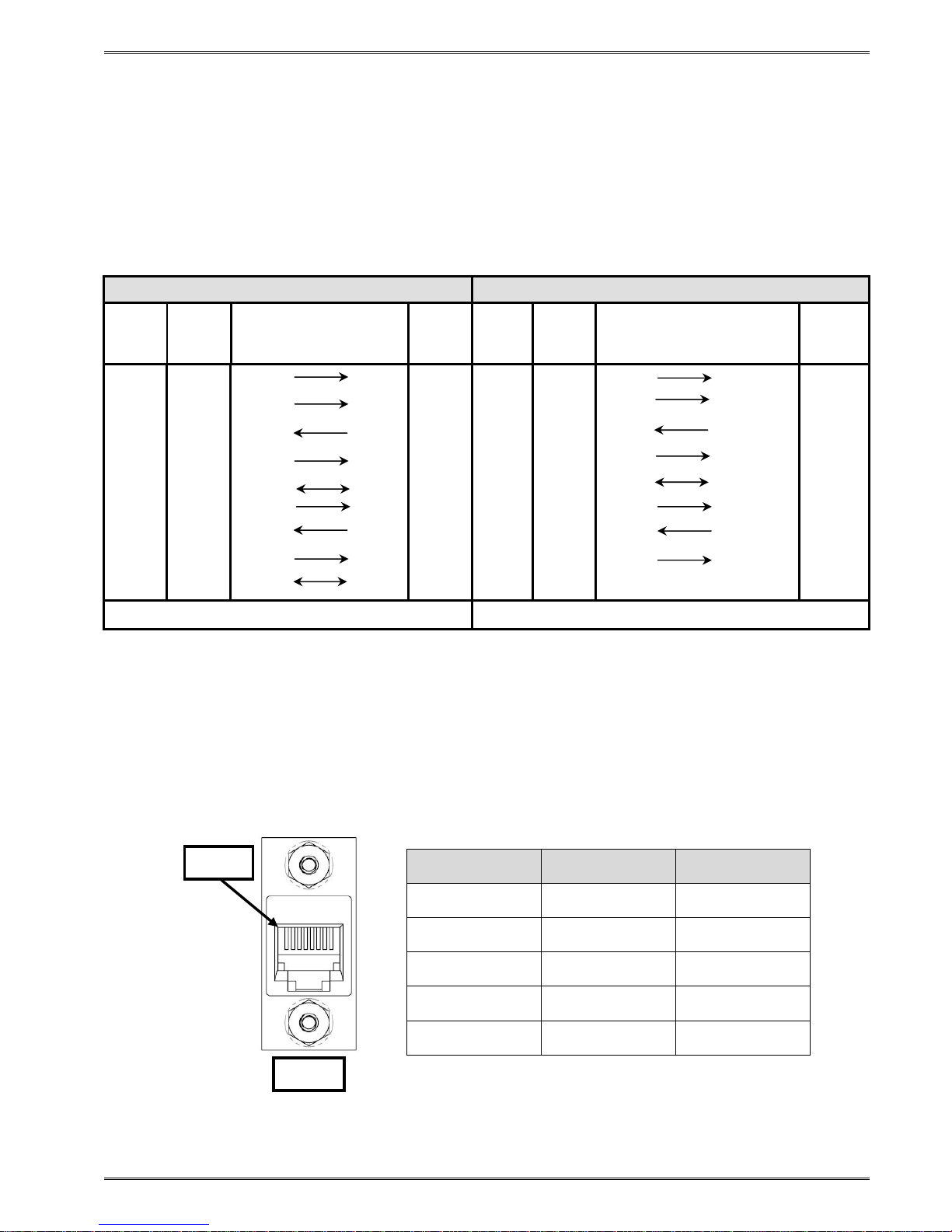
The printer provides a 9-pin female D-Sub connector, on the rear panel, for RS-232 serial
communication. The printer is configured as DCE (Data Circuit-terminating Equipment) so a
NULL modem cable is not necessary. A serial data cable is required to use serial
communications, refer to Table 3-1 below for correct cable configurations.
The factory settings, unless otherwise requested, are set at 115200 baud, 8 data bits, 1 stop
bit and no parity with hardware handshaking enabled. The baud rate is user selectable from
110 to 115,200 and uses software XON/XOFF flow control and/or hardware CTS/RTS
handshaking.
If XON/XOFF handshaking is used, the only signals that the printer requires are the RXD,
TXD, and GND signals. If the hardware handshaking is used, then the CTS and RTS signals
are required. The other signals are offered in the event that the host computer would
require them.
3-2 485TC Operator’s Manual - 880058-0100
Page 17
Chapter 3 Getting Started
PC
PC
Pin 1
RJ12
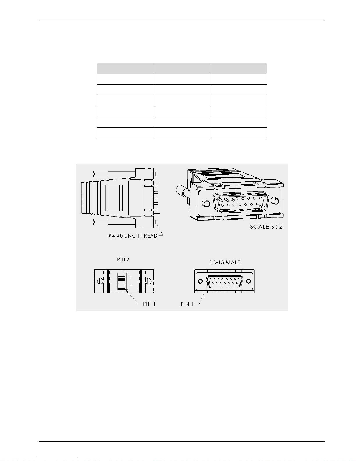
3.3.1 RS-232 Serial Cables
The printer uses a standard through serial cable, typically referred to as a modem cable,
which may be purchased through Microcom Corporation or a local computer supply
company.
For a 25-pin serial communication port – Use a 25-pin female to 9-pin male cable.
For a 9-pin serial communication port – Use a 9-pin female to 9-pin male cable.
9 to 9 Pin Cable 9 to 25 Pin Cable
DE-9
State
XX 1 DCD
XX 2 TXD
XX 3 RXD
HI 4 DTR
LO 5 GND
HI 6 DSR
DC 7 RTS
XX 8 CTS
HI 9 +5V
Pin #
Signals /
Directions
DE-9
Pin #
DCD
RXD 2 XX 2 TXD
TXD 3 XX 3 RXD
DSR 4 HI 4 DTR
GND
DTR 6 HI 6 DSR
CTS 7 DC 7 RTS
RTS 8 XX 8 CTS
+5V 9 HI 9 +5V -
State
1 HI 1 DCD
5 LO 5 GND
DE-9
Pin #
Signals /
Directions
DB-25
Pin #
DCD 8
RXD 3
TXD 2
DSR 20
GND 7
DTR 6
CTS 4
RTS 5
DC = DO NOT CARE XX = INDETERMINATE
Table 3-1 RS-232 Cable Configurations
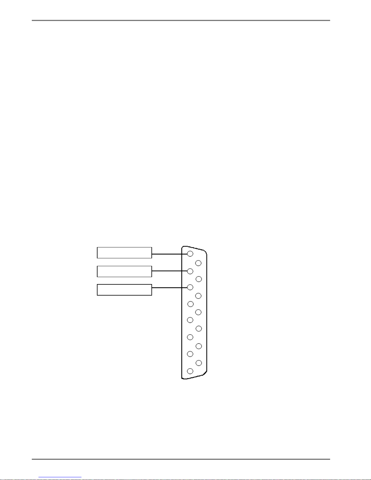
3.3.2 RS-232 Serial RJ-12
The printer is configured with a DB9 RS232 connecter by default but may be also
configured with the optional RJ12 connector. The figure below shows the wiring diagram of
the RJ12 connection.
9 Pin RJ12 Signal
2 2 TXD
3 3 RXD
5 4 GND
6 1 DTR
8 6 CTS
485TC Operator’s Manual - 880058-0100 3-3
Figure 3-3 RJ12 Serial Option Wiring
Page 18
Getting Started Chapter 3
Pin 1
- DR1
Pin 3
- DR2
Pin 2
- DO
3.4 USB Communication Interface
The printer is configured as a USB HID device so no specific drivers need to be installed.
Connecting the printer to the HOST system will install the printer.
3.5 Host USB Interface
The Host USB connector on the rear panel of the printer is used for updating the printer’s
application, Bootloader, and the fonts stored in the printer. Contact your Sales
Representative for additional information.
3.6 Ethernet Communication Interface
The printer is configured with a 10/100 BASE T Ethernet that is configured for DHCP out of
the box. After one minute of idle time after a power up, if a connection is not established,
the printer will switch to a static IP Address of 192.168.200.3 with a Subnet of
255.255.255.0 on port 9100.
The printer also has a resident Web Server running on IP 192.168.200.3 that may be used
to configure the printer as well.
3.7 Cash Drawer Option
The printer provides a DB15 connector to support the use of 24v cash drawer applications.
The Draw Kick-out solenoid current must be 1 amp or less to avoid current overloads. This
option is only available when using the FGL Emulation mode.
Figure 3-4 Cash Drawer Pin-out
3-4 485TC Operator’s Manual - 880058-0100
Page 19
Chapter 3 Getting Started
3.7.1 Cash Drawer RJ12 Adapter Option
Some cash drawers may use a RJ12 connector instead of the DB15 connector. The RJ12
adapter (060437-1000) is available as an optional component for these applications.
RJ12 Wire Color DB-15
1 WHITE X
2 BLACK 1
3 RED X
4 GREEN 2
5 YELLOW 3
6 BLUE X
Table 3-2 RJ12 Adapter Pin-out
Figure 3-5 Cash Drawer RJ12 Adapter
3.8 AUX Option
The AUX port option or auxiliary port on the printer is for custom application support.
485TC Operator’s Manual - 880058-0100 3-5
Page 20

Getting Started Chapter 3
3.9 Loading Media
Loading media into the printer is an easy process. Follow the instructions below to properly
adjust the paper guides and load the media.
1. Loosen the green thumbscrew at the back of the printer to adjust the green media
guides so that the media contacts both sides of the green guides.
2. Retighten the green thumbscrew once the guides have been adjusted.
3. Feed the media into the paper path, between the green guides, until you feel
resistance.
4. Once the printer detects paper in the printer, it will automatically feed and align the
paper so that it is properly positioned.
5. If the Autoload feature is disabled, you may also manually feed the paper through the
printer by lifting the print head release at the top of the printer and feeding the paper
through the printer.
6. Also, if the print button is pushed and held, the printer will manually feed the media
through the printer.
7. Once the media exits the front of the printer, release the Print Button.
Loosen thumb
screw to adjust the
guide, retighten the
thumbscrew when
finished
Figure 3-6 Loading Media
Insert media
between the
guides until
resistance is felt
3-6 485TC Operator’s Manual - 880058-0100
Page 21
Chapter 3 Getting Started
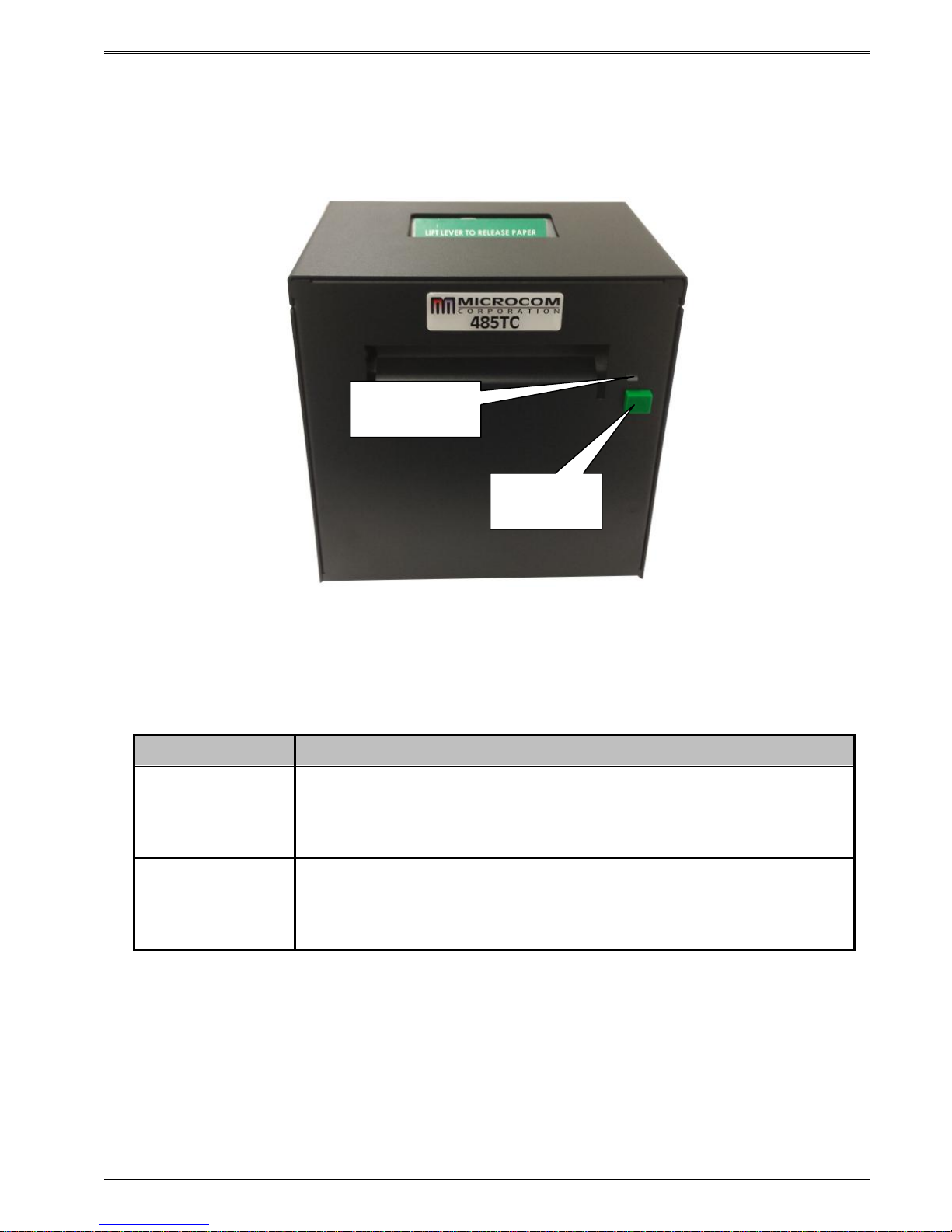
3.10 Print Button and Status Indicator Light
The Print Button and the Status Indicator Light are used to identify and perform many
functions. This section provides a description to familiarize you with the basic function of
the Print Button and the Status Indicator Light.
Figure 3-7 Print Button and Status Indicator Light
Status Light
Print
Button
3.10.1 Print Button
Operation Description
Button Press A button press is used to generate a Test Ticket and to clear
errors.
Button Pressed
and Held In
485TC Operator’s Manual - 880058-0100 3-7
Pressing and holding the button in will cause a line feed in certain
language modes.
Table 3-3 Print Button Description
Page 22

Getting Started Chapter 3
3.10.2 Status Indicator Light
Light Color Description
Solid Green
Solid Red
Indicates that the power is on and the printer is in a ready state.
Indicates an error has occurred. The printer will remain in this
state until the condition is removed. If an unexplained error
persists, contact your Service Representative.
Solid Amber
Flashing Red
Indicates that the printer is in the Boot Loader mode (MCB) and is
not running the printer application program.
A cutter error has occurred.
OR
A memory download operation was not successful.
OR
Power Spike or low voltage on the AC line. (The printer will
remain in this mode until the condition is removed and the printer
power is cycled.)
Table 3-4 Status Indicator Light Description
3.11 Printer Modes
The printer has three primary modes of operation. The different types of modes have an
impact on how the Print Button and the Status Indicator Light operate. This section is
intended to provide the user with an explanation of these different modes.
3.11.1 Ready Mode: GREEN
The printer is in the READY Mode when it is ready to print or has no pending activity. The
indicator light is GREEN, which indicates that the printer is ready to receive label formats
and/or commands.
Pressing the print button while in this mode generates a test ticket that contains setup
information about the printer. It is helpful to determine what mode it is in, what
communication port is active, and general operational details/
3.11.2 Halted Mode: RED
The printer is in the HALTED Mode when it has stopped due to an error condition. The
Status Indicator Light will be solid red in color when the printer has entered the HALTED
Mode. The printer will remain in this mode until the error has been corrected and cleared.
Once the error has been cleared, the printer will return to the Ready mode.
Pressing the button in this mode will cause the printer to attempt to clear the error and
return the printer to Ready mode.
3-8 485TC Operator’s Manual - 880058-0100
Page 23

Chapter 3 Getting Started
3.11.3 Diagnostic Mode
The Diagnostic Mode temporarily powers up the printer using factory default parameters.
Also, the printer’s current user configuration parameters and statistical information are
printed out on a Status Label. This provides useful information to help diagnose and
troubleshoot problems. The printer will use the factory default parameters until the printer
has been reset using a soft reset or by cycling power. The printer will then return to the
configuration shown on the Status Label.
3.11.3.1 Entering Diagnostic Mode
To enter the Diagnostic Mode, press and hold the Print Button “IN” while turning the printer
“ON.” Release the Print Button after printer light changes to green. The printer will enter
the DIAGNOSTICS Mode, and print the Statistics label and a print test pattern.
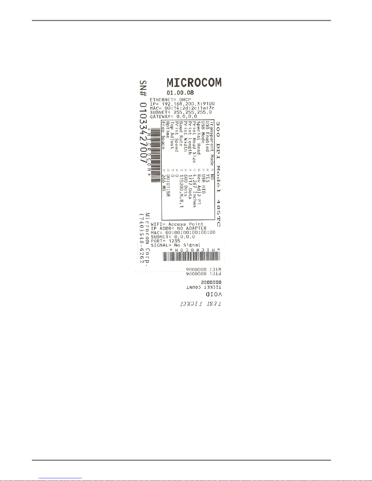
3.11.3.2 Statistics Label
The Statistics Label may be printed by entering the DIAGNOSTICS Mode.
Figure 3-8 Statistics Label Example
485TC Operator’s Manual - 880058-0100 3-9
Page 24
Getting Started Chapter 3
3.11.3.3 Test Ticket
The test ticket does not require that the printer be in the Diagnostics mode but it extremely
useful while troubleshooting the printer if problems arise. To generate a Test Ticket, simply
press the button and the test ticket prints out.
Figure 3-9 Test Ticket Example
3.12 TOF Sensor
The TOF Sensor is used to detect when media is present and is used in conjunction with the
Top-Of-Form operation. A TOF is when the printer uses the sensor to detect the edge of
the media and retracts the configured distance. See the D121 and D123 commands for
more details regarding the TOF operation.
A potentiometer adjusts the distance over which the LPD sensor will detect reflections. The
maximum range may be adjusted over a distance of 0.20” to 0.85”. Distances are
measured from the surface of the sensor to the reflecting surface. The sensor is set to the
maximum detection at the factory. This pot may be used to decrease sensor range to avoid
false reflections from stationary objects such as a cutter.
3-10 485TC Operator’s Manual - 880058-0100
Page 25

Chapter 3 Getting Started
The TOF Sensor is
located in front of
the cutter assembly
TOF sensor when
the cutter assembly
is not installed.
Figure 3-10 TOF (Top-Of-Form) Sensor
485TC Operator’s Manual - 880058-0100 3-11
Page 26

Getting Started Chapter 3
3.13 Media Roll Holder Option
The printer may be configured with an optional media holder for media wound on rolls. The
holder is designed to hold media cores of 1.5” or larger and contains media guides intended
to help prevent unnecessary unwinding of media.
Figure 3-11 Rolled Media Holder
3.14 Ticket Catch Tray Option
The printer may be configured with an optional ticket catch tray that is used to catch the
printed tickets. The trays are available in a couple of standard sizes.
Figure 3-12 Ticket Catch Tray
3-12 485TC Operator’s Manual - 880058-0100
Page 27

Chapter 3 Getting Started
3.15 Wristband Media Adapter Option
When 1” wide wristband media is being used, the wristband option should be installed. The
wristband guide is inserted into the media guide and is locked into place.
Wristband Guide
Insert into media guide
making sure that it is
flush against the green
media guide
Figure 3-13 Wristband Media Adapter
Loosen locking nut and
slide guide into place
and retighten into place
485TC Operator’s Manual - 880058-0100 3-13
Page 28

Getting Started Chapter 3
3.16 Qualsoft Windows Driver
3.16.1 Installing the Windows Driver
This section explains the driver installation process. The Qualsoft Windows print driver may
be used with Windows 7, 8.1, and 10 operating systems. If the printer is intended to be
used on a USB connection, the appropriate USB driver must be installed before the printer
is able to be used with the driver. The X38 based products use an FTDI based driver while
the X85 based products use a Microcom Corporation based driver.
The driver requires that the User has ADMIN privileges in order to install the driver. The
installation process sample shows the Windows 7 installation.
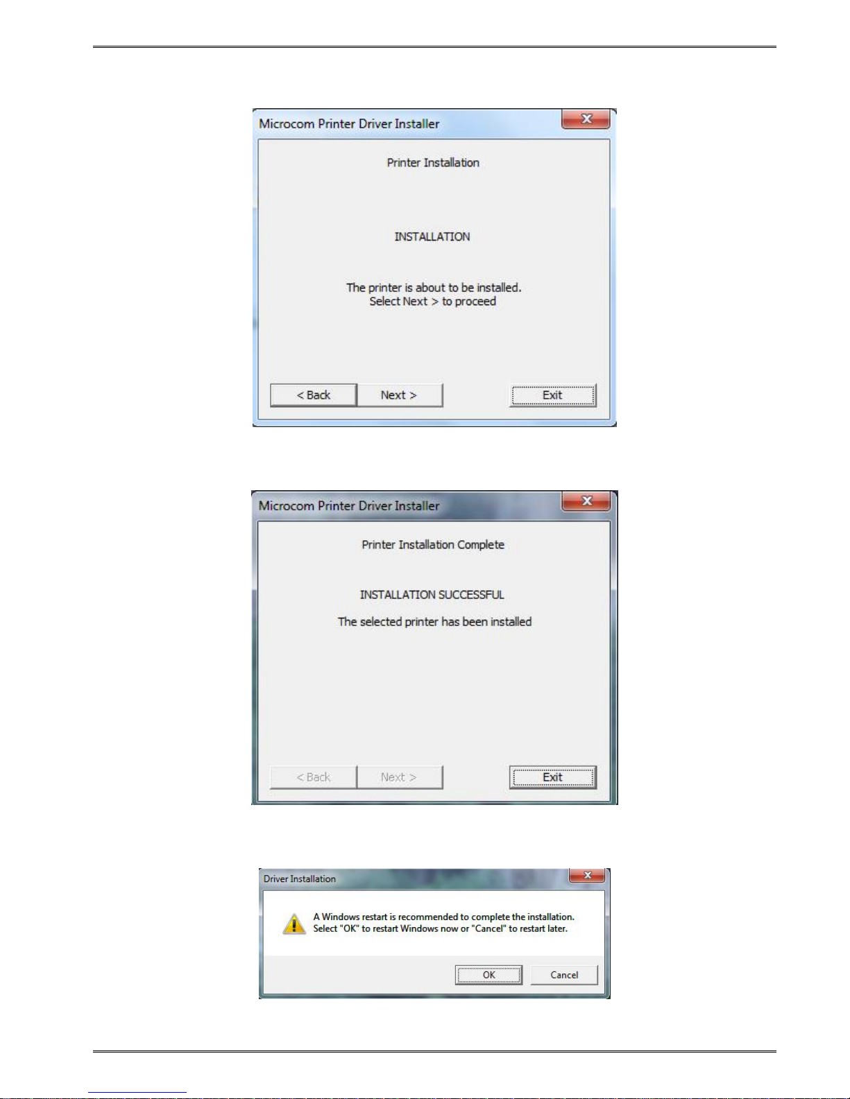
1. Right click on the installer, and select “Run as administrator”.
2. Click the “Next” to continue the installation.
3-14 485TC Operator’s Manual - 880058-0100
Page 29

Chapter 3 Getting Started
3. Wait for the installer to finish setting up the driver files.
4. Select the New install or Uninstall existing driver if already running a Qualsoft version or if
installing more than one printer, select the Install another printer model (Copy n).
485TC Operator’s Manual - 880058-0100 3-15
Page 30

Getting Started Chapter 3
5. Select the Model number of the printer being installed.
6. Select the communication port that is going to be used with the printer.
3-16 485TC Operator’s Manual - 880058-0100
Page 31
Chapter 3 Getting Started
7. Select next to start the installation.
8. Once the installation is complete, select “Exit” to finish the installation.
9. Select “OK” if prompted to restart and complete the installation.
485TC Operator’s Manual - 880058-0100 3-17
Page 32

Getting Started Chapter 3
3.16.2 Configuring the Driver
This section will explain how to configure the Windows Driver for proper operation. The
example below also shows a Microcom Thermal Printer under Unspecified devices. This is
the USB driver that is loaded when the printer is powered on and the printer USB port is
connected to the printer.
Under Devices and Printers, you should see the printer model that was installed. Right click
on the icon and select Printer properties to setup and to change the driver settings.
3-18 485TC Operator’s Manual - 880058-0100
Page 33

Chapter 3 Getting Started
3.16.3 Printer Properties Page - General tab
This opens the printer properties page. From this screen, Print Test Page may be selected
to generate a test page that is sent to the printer. The test page is printed on the media size
and type that are specified in the driver preferences.
485TC Operator’s Manual - 880058-0100 3-19
Page 34

Getting Started Chapter 3
3.16.4 Printer Properties Page - Ports tab
Selecting the Ports tab at the top allows the printer port to be changed if connecting to a
different printer communication port.
3-20 485TC Operator’s Manual - 880058-0100
Page 35

Chapter 3 Getting Started
3.16.5 Printing Preferences - About tab
Selecting the Preferences icon at the bottom left of the Printing properties window opens the
driver “About” tab. This shows the driver version number and release date.
3.16.6 Printing Preferences - Print tab
The Print tab shows the available options that may be set. Typically, these are already set
for proper operation and do not need to be adjusted.
485TC Operator’s Manual - 880058-0100 3-21
Page 36

Getting Started Chapter 3
3.16.6.1 Print tab - Advanced
The Advanced tab is used to specify the print resolution and the printhead width. This tab is
automatically set when selecting the printer model to install and should be ignored. This
screen is typically used for development testing and custom solutions.
3.16.7 Print tab - Halftone Adjustment
The Halftone Adjustment icon opens the dialog windows below. This allows the user to
manipulate the image settings that the driver uses to produce images.
3-22 485TC Operator’s Manual - 880058-0100
Page 37

Chapter 3 Getting Started
3.16.8 Print tab - Halftone Properties
The Halftone Properties page allows for dithering options and additional image manipulation
to alter the image that is produced and printed.
3.16.9 Print tab - User Commands
The User commands tab allows for the user to pass printer commands directly into the data
stream. This is typically used for either troubleshooting or custom override commands.
485TC Operator’s Manual - 880058-0100 3-23
Page 38

Getting Started Chapter 3
3.16.10 Printing Preferences - Paper tab
The Paper tab is where the user adds custom form sizes and adjusts minor handling effects.
The form sizes that are created here are added to the Windows Print Server Properties for
the model installed.
3.16.10.1 Paper tab - Rotation
The rotation setting rotates the image being printed. This is used when Portrait or
Landscape is used. The “A” image shows the rotation setting impact.
3.16.10.2 Paper tab - Units
This is used to select the units that the driver uses for most measurements. Some units are
in dots or pixels and should be entered as such.
3.16.10.3 Paper tab - Page Sizes
This is where the user enters forms to the Print Server Properties of the driver. Select the
drop down menu to select standard forms that have been installed with the driver or enter
the size of your form and select the New icon to create a form size that matches your media.
3.16.10.4 Paper tab - Mirror
Selecting this option will cause the image to appear like it being observed in a mirror.
3-24 485TC Operator’s Manual - 880058-0100
Page 39

Chapter 3 Getting Started
3.16.10.5 Paper tab - Default
This button will cause the driver to load in its default settings for the model driver installed.
Please note that this default may not represent your media type or size.
3.16.11 Printing Preferences - Media tab
The Media tab is used to set specific setting of the media size and operations that in a form
that the printer requires to maintain correct registration.
3.16.11.1 Media tab - Settings
The Settings control the Type of registration that the printer will use to align the media being
used and the Darkness of the image being printed.
3.16.11.1.1 Settings - Type
This field sets the registration method that the printer will use to register job to job. This
type should be set to the type of registration mark that is used to indicate the form size. The
Continuous setting instructs the printer to ignore registration marks and will move media
based on the form size settings. The Blackline setting cause the printer’s reflective sensor
to look for a blackline mark and register based on the other Feed options. The Diecut and
485TC Operator’s Manual - 880058-0100 3-25
Page 40

Getting Started Chapter 3
Blowhole settings cause the printer to use its transmissive sensor to detect the backing
material between labels or an actual hole in the media.
3.16.11.1.2 Settings - Darkness
This sets the darkness or contrast that the printer uses to image. As the value increases,
the higher the thermal temperature setting is used for imaging. The lowest temperature that
produces quality images should be used to extend the printhead life.
3.16.11.2 Media tab - Feed Options
The Feed options handle post printing dispensing and media options that are used by the
printer to properly register the media from page to page.
3.16.11.2.1 Feed Options - Mode
The Mode is used to select the type of dispense option used after the printer has printed.
The options include None, Advance when idle, Advance every label, Cut after label, and Cut
with LPD.
Selecting the “None” option will disable the dispense modes. The printer will print the job
and then stop without performing any dispense option.
The Advance when idle dispense option causes the printer to advance the Dispense
Distance after the printer’s communication port has gone idle. This mode does not require a
label present sensor to function. For example: If printing 5 jobs, the printer would advance
after printing the fifth job.
The Advance every label is a dispense mode that does use the printer’s label present
sensor. The printer will print a job and then advance the job by the Dispense Distance. A
second job will not be processed until the printed/dispensed job has been taken (the LPD no
longer detects the advanced job). Once the job has been taken, the printer will process the
next print job. The Advance/Retract delay is also used in conjunction with this command.
This delay starts after the label has been taken.
Cut after label causes the printer to advance the Dispense Distance after the job has been
printed and then cycles the cutter. This mode does not use the Label Present Sensor.
The Cut with LPD is a mode that the printer will advance the Dispense Distance after
printing and cut the label. The LPD is used to prevent the next job from printing until the
current job has been taken by the user.
3.16.11.2.2 Feed Options - Gap Height
This field is used to specify the height of the backing material between labels typically found
on die cut media types. As the media is moved through the printer, the height of the Gap
would be what the printer’s transmissive sensor would detect and use for page to page
registration.
3.16.11.2.3 Feed Options - Blackline/Blowhole Height
This field is used to specify the height of the blackline or Blow hole that is used for
registration on media types containing a blackline of blowhole. The printer uses its reflective
sensor to detect the blackline as the media is passed through the printer and would use its
transmissive sensor to detect the blowhole.
3-26 485TC Operator’s Manual - 880058-0100
Page 41

Chapter 3 Getting Started
3.16.11.2.4 Feed Options - Dispense Distance
This is the distance that the printer uses to move the media forward to dispense and it used
in conjunction with the Mode. The printer moves out this distance and then would retract
the same distance so it does not impact registration.
3.16.11.2.5 Feed Options - Advance/Retract Delay
This field is used to specify how long the printer will wait in msec after the media has been
taken when the Advance every label mode or Cut with LPD modes are used.
3.16.11.2.6 Feed Options - Registration Offset (DRM)
The registration offset is used by the printer to calculate the correct SPG (Steps Past Gap)
value that the printer will use for registration. This distance is from the first printable area of
the media to beginning of the registration mark as it would pass through the printer.
3.16.11.2.7 Feed Options - Dot2Gap
This field is the distance of the registration sensors to the dot row and is used to calculate
the Steps past gap or SPG value used to align the print from page to page. This value is
fixed value for each printer model. Some printer models have a different sensor location for
the blackline reflective sensor and the Transmissive Gap sensor. Please review the printer
manual for more information regarding the correct value for the Dot2Gap. The value
entered is in dots or pixels.
3.16.11.2.8 Feed Options - SPG
The Steps Past Gap (SPG) is a format header parameter that the printer uses to register the
page properly. If the Auto SPG is checked, the driver will automatically calculate the proper
SPG based on the other entered fields. If unchecked, the SPG is entered in manually. This
value is entered in as dots.
3.16.11.2.9 Feed Options - Activate Gap Detection (dots)
The Activate Gap Detection is the distance in dots that the printer will move media before
trying to detect a registration mark. The default of 1 typically works for most media types. If
the media being used contains preprint in the sensor area, the AGD may need to be used to
disable registration detection until passing over the preprinted areas.
3.16.12 Printing Preferences - Presenter tab
The Presenter tab controls the operation of the optional presenter available on some printer
models. A presenter is a post printing device that typically takes a printed and cut form and
presents it to the user only after is has printed completely. Not every printer model is
capable of running a presenter. Check with your printer model operator’s manual to see if a
presenter is supported. This tab is ignored on models that do not support the use of a
presenter.
485TC Operator’s Manual - 880058-0100 3-27
Page 42

Getting Started Chapter 3
3.16.12.1 Presenter tab - Configuration
The fields listed under the Configuration section control the Presenter operation on printer
model that are compatible with the presenter.
3.16.12.2 Configuration - Modes
This is used to select the mode of the presenter. The valid modes are enabled,
passthrough, and disabled. When selecting Enabled, the printer with presenter would
present the media using the other fields for operation while selecting Passthrough mode will
simply cause the presenter to run while the printer is printing.
3.16.12.2.1 Configuration - Take-Label/Retract Timeout (secs)
This field controls the time that the presenter will present the paper before retracting into the
waste bin.
3.16.12.2.2 Configuration - Maximum Present Distance (inch)
This is the maximum size that the printer will present when using the enabled mode. This
value is in inches.
3-28 485TC Operator’s Manual - 880058-0100
Page 43

Chapter 3 Getting Started
3.16.12.2.3 Configuration - Loop Height (1/10 inch)
The Loop Height is a value in 1/10 inch that the printer uses to delay the presentation of the
media. The printer would print and form a loop at the presenter and once this value is
reached, the presenter would present.
3.16.12.3 Configuration - Advanced
The Advanced button is included as a manual override of the recommended settings that
the presenter will use for the various speeds. Typically, these values do not need to be
adjusted for the presenter to function.
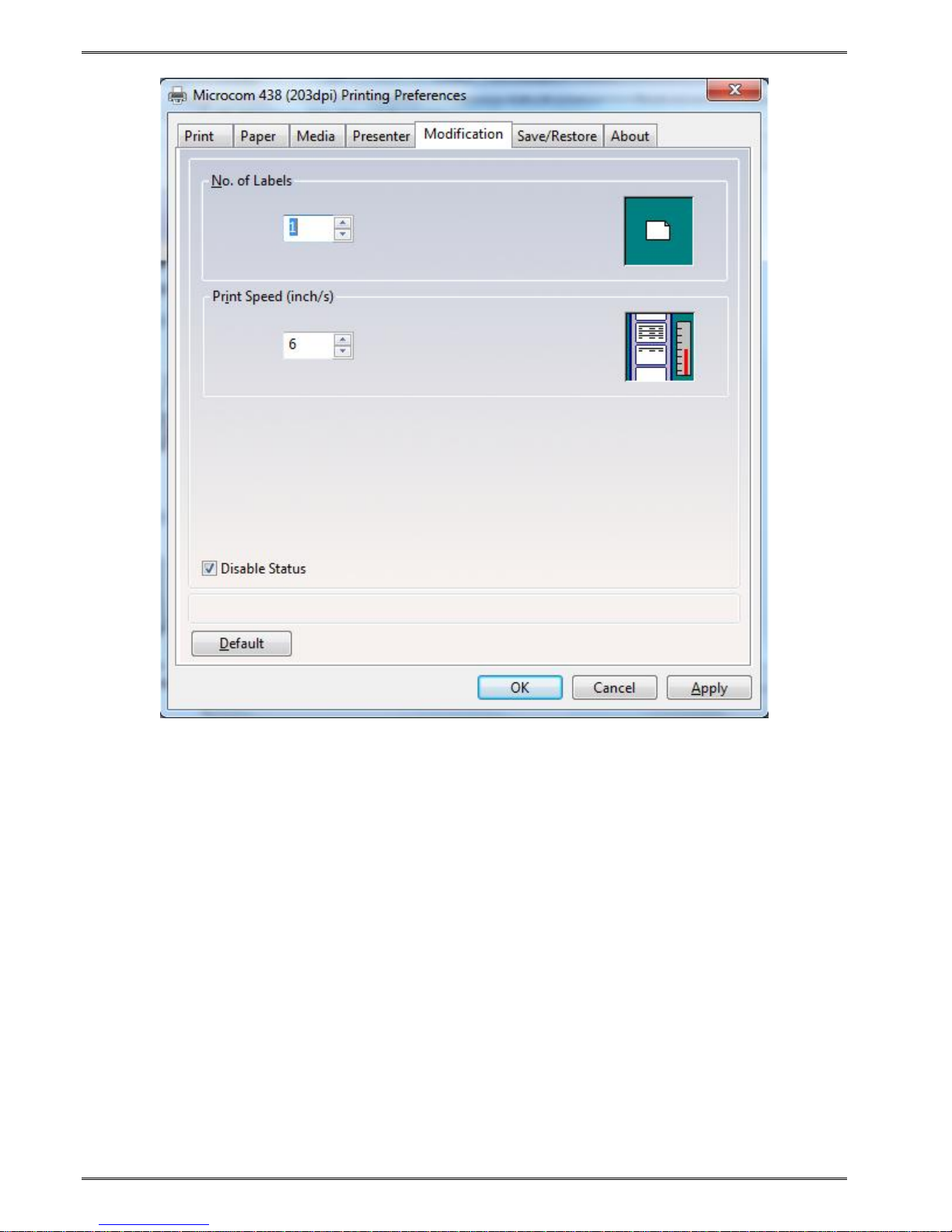
3.16.13 Printing Preferences - Modification tab
This tab is used to control the number of copies, print speed, and port monitor status
enable.
3.16.13.1 Modification - No of Labels
This field controls how many copies of the current page will be printed.
3.16.13.2 Modification - Print Speed (inch/s)
The Print Speed filed controls the print speed that the printer uses to print a page.
3.16.13.3 Modification - Disable Status
The Disable Status checkbox is used to control whether the Port Monitor Status popup
window is displayed or not. This is used to get real time status from the printer while
printing via the Windows driver.
485TC Operator’s Manual - 880058-0100 3-29
Page 44
Getting Started Chapter 3
3-30 485TC Operator’s Manual - 880058-0100
Page 45

Chapter 3 Getting Started
3.16.14 Printing Preferences - Save/Restore tab
The Save/Restore tab is used to export or import driver settings and to force back to the
factory defaults based on the printer model installed.
3.16.14.1 Save/Restore - Restore settings from file…
This is used to import or restore driver settings from a .MDS file. The driver settings are
contained within a .MDS file and may be restored or configured if imported using the
Restore feature.
3.16.14.2 Save/Restore - Save settings to file…
This is used to export or save the current settings in a .MDS file. This file contains the driver
setup used to configure the driver.
3.16.14.3 Save/Restore - Restore factory defaults…
This will force the driver defaults of the printer model installed.
3.16.15 Status Messages
This section describes the Windows compatible Status messages that are displayed in
spooler and the Status Monitor feature found on the Modification tab. These messages may
485TC Operator’s Manual - 880058-0100 3-31
Page 46

Getting Started Chapter 3
be extracted using the GetPrinterData MSDN API call. The standard message and the
printer meaning are listed below.
3.16.15.1 PRINTER_STATUS_WAITING
This message indicates that the printer is okay and ready to print. LDS1 control language
printer message would be the >READY<.
3.16.15.2 PRINTER_STATUS_BUSY
Message indicates that the printer is busy printing a job. No LDS1 equivalent control
language printer message.
3.16.15.3 PRINTER_STATUS_PAPER_OUT
This message indicates that the printer does not detect media in the printer or has run out of
media. The LDS1 equivalent control language printer message would be >STOCK NOT
LOADED< or >LOW STOCK<.
3.16.15.4 PRINTER_STATUS_PAPER_JAM
Message is used to indicate that the printer has detected a media jam. The LDS1 control
language printer message would be the >LPD STOCK JAM<.
3.16.15.5 PRINTER_STATUS_PAPER_PROBLEM
This message is used to indicate that the optional >INPUT 1< sensor is active. The >INPUT
1< message is the equivalent LDS1 control language printer message that is reported.
3.16.15.6 PRINTER_STATUS_USER_INTERVENTIO N
This message indicates that the printer is in an error condition that needs to be corrected
before the printer may continue. The LDS1 messages that generate this error would be
>CUTTER ERROR<, >DATA ERROR<, >FAIL TIMEOUT<, or >FAIL SIZE< LDS1 control
messages.
3.16.15.7 PRINTER_STATUS_OFFLINE
Message indicates that the printer is powered down or the driver is unable to communicate
with the printer. No LDS1 equivalent control language printer message.
3.16.15.8 PRINTER_STATUS_OUTPUT_BIN_FULL
This message is used to report that the printer is reporting that its catch tray is full or that the
printer’s media is advanced blocking the LPD sensor while in a dispense mode. The LDS1
control language messages that generate this message would be the >TRAY FULL< and
>TAKE LABEL< messages.
3.16.15.9 PRINTER_STATUS_DOOR_OPEN
This message is generated when the printer detects that its printhead assembly is not fully
closed. Not all printers support this feature. The LDS1 control language message
equivalent would be the >HEAD UP< message.
3.16.15.10 PRINTER_STATUS_IO_ACTIVE
This message is used to indicate that the optional >INPUT 2< sensor is active. The >INPUT
2< message is the equivalent LDS1 control language printer message that is reported.
3-32 485TC Operator’s Manual - 880058-0100
Page 47

Chapter 3 Getting Started
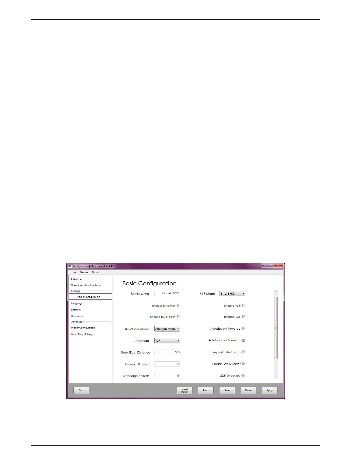
3.17 Configuration Application
The 485 Configuration Application and its dependencies are installed by running the
provided setup utility. Most modern versions of Windows require Administrator privileges to
perform this type of installation.
For 32-bit Windows systems, run Microcom485ConfigurationAppSetup_x86.exe. For 64-bit
Windows systems, run Microcom485ConfigurationAppSetup_x64.exe.
The setup utility will guide you through the installation process. Take note of the installation
directory. By default, application package files will be placed in either the “C: Program Files”
or “Program Files (x86)” directory.
3.17.1 Selecting a Device
The 485 Configuration Application allows a printer to be configured via an RS-232 serial,
USB serial, USB HID, or Ethernet connection to a computer. With the exception of RS-232,
all of these interfaces can be enabled/disabled on the printer. To determine which
interfaces are enabled, a diagnostic label may be printed by powering down the printer and
powering it back on while holding the front panel button OR simply by pressing the front
panel button while in FGL mode. Once you know which interface to use, simply select it on
the left panel, choose it from the selection list on the right, and click OK.
3.17.1.1 Configuration Application - Serial (USB / RS-232)
RS-232 and USB CDC (USB serial) connections will be recognized as COM devices by
Windows. Typically, more than one COM device will be found by the application. To
determine which COM port is bound to the Model 485, check the ‘Devices and Printers’
menu in the Windows Control Panel. The printer should be listed as Microcom 485 Thermal
Printer (COM#) - choose this same COM device within the 485 Configuration Application to
configure the printer using RS-232 or USB ser i al as the active interface.
485TC Operator’s Manual - 880058-0100 3-33
Page 48
Getting Started Chapter 3
3.17.1.2 Configuration Application - USB HID
A USB Human Interface Device (USB HID) is a generic classification of an input device.
Windows comes pre-loaded with the USB HID drivers necessary to communicate with the
Model 485, which means there is nothing for the user to install.
As is the case with COM devices, the 485 Configuration Application will typically find more
than one USB HID device. Microcom printers are identified as such and will be listed as
“Microcom - <Model> - <Serial Number>”. For example, the device selection box would list
a Microcom 485 as “Microcom - 485 - 123456”. Choose the desired printer from the
selection list. If more than one Microcom 485 is connected to your computer and you do not
know the serial number, press the push button on the printer to print a test ticket while in
FGL mode or a double press while in Graphics mode.
3.17.1.3 Configuration Application - Ethernet
If your Microcom 485 and computer share an ethernet network connection, the 485
Configuration Application can use the printer IP address and port to communicate. In the
text field, enter the printer’s IPv4 address in its usual format of “aaa.bbb.ccc.ddd”, then enter
the port that the printer is configured to listen on. If you do not know the port or the IP
address, press the push button on the printer to print a test ticket with this information (FGL
mode only). The default IP address and port are 192.168.200.3 and 9100, respectively.
3.17.2 Configuring a device
Once you have chosen the appropriate interface and successfully connected to the 485
printer, the configuration window will appear. The window is essentially made up of three
panels: the configuration categories (left), configuration values (right), and printer control
button panel (bottom). Configuring your 485 is as simple as changing the value, clicking
Apply, and then clicking Restart.
3-34 485TC Operator’s Manual - 880058-0100
Page 49

Chapter 3 Getting Started
3.17.2.1 Applying changes
To apply all configuration changes to the printer, click the Apply button. When this button is
clicked, the values held by the on-screen controls are sent to the printer. The printer must
be restarted for the changes to take effect. A restart can be performed by clicking the
Restart button or by manually turning off and on the power switch on the printer. When the
printer reboots, the changes will be in place.
3.17.2.2 Reverting changes
When the Revert button is clicked, the values held by the on-screen controls will change
back to what they were when the device was first connected to when the application started.
In other words, the revert point is the point at which the Configuration window is first loaded.
If you have applied changes but have not restarted the printer for them to take effect,
clicking Revert will undo all the changes even if the Apply button has been clicked.
3.17.2.3 Saving/loading configuration files
A configuration file is generated by the application when the Save button is clicked, or when
the File->Save configuration menu option is selected. Clicking either of these two options
will open a Windows Save As dialog in the application output directory. A unique filename is
generated by default to avoid overwritten configurations.
To load a configuration file, click the Load button or the File->Load configuration menu
option. The application will open a file dialog in the application output directory. Select a
configuration file, and click “Open” to update the on-screen controls with the configuration
values contained in the file. Note that loading a file does not send the configuration to the
printer until the Apply button is clicked.
3.17.3 Application preferences
The Preferences window can be accessed by selecting File->Preferences from the menu
bar. Within the preferences you can change the application output directory, gain access to
read-only settings (with a password of course), and more.
485TC Operator’s Manual - 880058-0100 3-35
Page 50

Getting Started Chapter 3
3-36 485TC Operator’s Manual - 880058-0100
Page 51

Chapter 4 Printer Maintenance
4.1 Maintenance Schedule
It is important to note that the optimum print quality and print head life is achieved by
maintaining a clean printer and print head. A Microcom Corporation approved cleaning kit
(part # 040005-0000) is available; contact your sales representative for purchasing
information.
AREA METHOD INTERVAL
Foam tipped swab, cotton tipped
Print Head
Drive Roller
Peel Edge
Interior Cleaning
Exterior Cleaning
Table 4-1 Recommended Maintenance Schedule
CAUTION: Microcom Corporation will not be held responsible for
damage caused by any non-approved solvent, cleaning material and/or
method. The use of such non-approved materials and/or methods may
void appropriate expressed or implied warranties.
swab, or thermal printer cleaning
card dampened with Isopropyl
Alcohol.
Foam tipped swab, cotton tipped
swab, thermal printer cleaning
card, or lint-free cloth dampened
with Isopropyl Alcohol
Foam tipped swab, cotton tipped
swab, thermal printer cleaning
card, or lint-free cloth dampened
with Isopropyl Alcohol
Compressed air, static protected
vacuum cleaner, soft-bristle
brush, and/or lint-free cloth
dampened with Isopropyl Alcohol.
Lint-free cloth dampened with a
mild, non-abrasive general
purpose cleaner.
After every roll of
media or every 512
feet of tag stock or
fanfold media.
After every roll of
media or every 512
feet of tag stock or
fanfold media.
As Needed.
As Needed.
As Needed.
4.2 Thermal Printer Cleaning Card
Any decline in print quality, voids or dropout areas in bar codes and/or graphics may
indicate that the print head is dirty and needs to be cleaned. The necessary cleaning
materials can be purchased through Microcom Corporation by contacting your sales
representative and ordering the Cleaning Kit, part # 040005-0000. The print head should be
cleaned after every roll of media or after every 512 feet of fanfold media (a typical stack of
tag or fanfold media is approximately 3,200 tags).
485TC Operator’s Manual - 880058-0100 4-1
Page 52

Printer Maintenance Chapter 4
A thermal printer card is the quickest and easiest way to clean the print head, drive roller,
and peel edge all at the same time. Follow the steps below for the proper cleaning
procedure.
1. Remove any installed media.
2. Dampen both sides, on one end, of the cleaning card with isopropyl alcohol or use a
pre-moistened cleaning card.
3. Release the printhead assembly to insert the cleaning card under the printhead.
Figure 4-1 Releasing the Printhead Assembly
Figure 4-2 Rotate the Printhead Assembly to the Open Position
4-2 485TC Operator’s Manual- 880058-0100
Page 53

Chapter 4 Printer Maintenance
4. Re-latch the printhead assembly, hold the printer, and slowly pull the cleaning card
(you will feel resistance) out of the printer.
Figure 4-3 Remove the Cleaning Card
5. Reinstall the media and check print quality.
6. Repeat cleaning steps if necessary.
Thermal cleaning cards should not be used more than three times each. Extremely dirty
cards should be disposed of immediately.
4.3 Internal Cleaning
The overall internal cleaning of the printer is important to help reduce the dust and other
contaminates residing in the printer that may attach to the print head or drive roller and
affect the printer’s performance.
1. Remove any installed media.
2. Turn the printer power “OFF.”
3. Release the printhead assembly and rotate to the open position.
4. The exposed Drive Roller, Printhead, and Paper Path may be cleaned using a cotton
swab or lint-free wiping rag dampened with is opropyl alcohol.
485TC Operator’s Manual - 880058-0100 4-3
Page 54

Printer Maintenance Chapter 4
Blow dust out with
compressed air or
vacuum with anti-static
vacuum cleaner.
Clean Paper Path with
lint-free cloth or swabs
dampened with isopropyl
alcohol.
Clean Drive Roller with
lint-free cloth or swabs
dampened with isopropyl
alcohol. (Drive Roller
can be rotated by hand.)
Figure 4-4 Internal Cleaning
4.4 Print Head Maintenance
If print quality has not improved after using a thermal cleaning card, or if one is not
available, foam or cotton tipped swabs or a clean lint-free cloth dampened with isopropyl
alcohol may be used. Follow the steps below to clean the print head.
1. Release the Print Head Assembly and rotate to the open position.
2. With a foam or cotton tipped swab or soft, lint-free cloth dampened with isopropyl
alcohol, clean the thermal elements by gently rubbing the swab down the length of
the print head dot row. Allow for the alcohol to evaporate, then repeat if necessary.
3. Reinstall media and run labels to check print quality.
4. If poor print quality persists, print head or other parts may be damaged.
CAUTION: Isopropyl Alcohol or other approved non-Abrasive
solution should be used to clean the drive roller. The use of other
cleaning solvents or materials is not recommended and may
degrade the performance of the drive roller.
4-4 485TC Operator’s Manual- 880058-0100
Page 55

Chapter 4 Printer Maintenance
The printhead dot row
should be cleaned to
remove any
contaminates that may
impact print quality.
Figure 4-5 Cleaning the Print Head
4.5 Replacing the Drive Roller
Over time, the platen may harden and cause print issues and need to be replaced. The
printer is equipped with an easy replaceable drive roller assembly.
1. Loosen and unscrew the 2 pressed in captive screw that holds the top cover in place
and rotate to the open position.
Figure 4-6 Releasing the Print Mechanism
2. Release the Print Head Assembly and rotate to the open position.
485TC Operator’s Manual - 880058-0100 4-5
Page 56

Printer Maintenance Chapter 4
3. Unscrew the Cutter or Tear Assembly using the mounting screw that is located in the
bottom center on the front of the Print Mechanism.
Cutter or Tear
Assembly
Mounting Screw.
Figure 4-7 Cutter or Tear Assembly Mounting Screw
4. Squeeze the white plastic bushing together on both sides of the platen to release
from the sheet metal and lift the platen assembly up and out of the printer.
Squeeze the tabs
together on both
sides and lift the
roller out of the
printer.
Figure 4-8 Removing the Platen
4-6 485TC Operator’s Manual- 880058-0100
Page 57

Chapter 4 Printer Maintenance
5. Replace the assembly with a new platen assembly making sure that the bushings
snap into the sheet metal.
6. Reattach the cutter or tear assembly taking care to locate the top lip of the assembly
to the hook detail in the sheet metal.
Hook detail that
the cutter or tear
assemblies are
attached too
Figure 4-9 Cutter or Tear Assembly Mounting Hook
7. Close the printhead assembly to the home position and latch into place.
8. Reinstall the front and top covers and tighten the top cover thumbscrews.
4.6 Adjusting Printhead Pressure
The printer has two head pressure settings to support both narrow and wide media types.
The printhead pressure is typically changed to a lighter pressure when the media being
used is 2” wide or less. Extra drag on the platen may cause feeding issues if a heavy spring
pressure is used with the narrow stock types.
The heavy spring pressure is typically used on media that is over 2” wide. The spring
pressure is not intended to overcome print quality issues. If light print is detected, please
adjust your printer’s contrast setting (^D36) and/or verify that the thermal coating on the
media is sufficient.
485TC Operator’s Manual - 880058-0100 4-7
Page 58

Printer Maintenance Chapter 4
Figure 4-10 Narrow Media Light Spring Setting
Figure 4-11 Wide Media Heavy Spring Setting
4-8 485TC Operator’s Manual- 880058-0100
Page 59

Chapter 5: Troubleshooting
5.1 Troubleshooting Tips
The printer fails to turn “ON” and the status indicator light fails to light:
ü Verify that the power cord is connected to the printer, as well as the AC outlet.
ü Verify that the printer power switch is in the “ON” position.
ü Verify that the AC outlet is functioning properly.
ü Contact your Service Representative.
The printer has no communication:
ü Verify that the communication cable is properly connected to the printer and an
available communication port on the host computer.
ü Verify that the host communication port is functioning properly.
ü Verify that the printer and the host communication parameters are set correctly.
ü Verify that nothing else is configured on the same port.
ü Is the printer in an Error?
ü Contact your Service Representative.
Vertical blank or light lines appear on printed areas:
ü Clean the print head.
ü Print head may need to be replaced.
ü Contact your Service Representative.
The print does not align to my media:
ü Verify that the media contains some sort of registration mark.
ü Verify that the printer is received proper formatting instructions.
ü Verify that nothing is blocking the internal registration mark sensors.
ü Contact your Service Representative.
485TC Operator’s Manual - 880058-0100 5-1
Page 60

Troubleshooting Chapter 5
The status indicator light is solid amber in color:
ü Indicates that the printer is the Bootloader, make sure that an application has been
installed.
ü Contact your Service Representative.
The status indicator light is solid red in color:
ü The printer has an error and requires service before printing will continue.
ü Verify that media has been loaded in the printer properly.
ü Press the print button to attempt to clear the error.
ü Cycle power to reset the printer.
The status indicator light is flashing red in color:
ü Generally due to a power fail error.
ü Verify that the AC line-voltage is present at the AC outlet.
ü Cycle power.
5-2 485TC Operator’s Manual - 880058-0100
Page 61

Index
General Index
Agency Approvals................................................................................................................................................. 1-1
Alphanumeric ...................................................................................................................................................... 7-5
Bar codes ................................................................................................................................................................1
Barcode ............................................................................................................................................................... 7-5
Black-line............................................................................................................................................................. 7-5
Blow-hole ............................................................................................................................................................ 7-5
Cleaning Kit .................................................................................................................................................. 2-2, 4-1
Communication
RS-232C Serial ................................................................................................................................................. 3-2
Continuous media ................................................................................................................................................ 7-5
CTS ..................................................................................................................................................................... 7-5
Cutter ................................................................................................................................................................. 7-5
Data Bits .............................................................................................................................................................. 1-1
DCD .................................................................................................................................................................... 7-5
DCE ..................................................................................................................................................................... 7-5
Die-cut media ...................................................................................................................................................... 7-5
Direct Thermal ..................................................................................................................................................... 7-5
DPI ...................................................................................................................................................................... 7-5
Drive Roller ................................................................................................................................................... 4-1, 7-5
DSR ..................................................................................................................................................................... 7-5
DTE ..................................................................................................................................................................... 7-5
DTR ..................................................................................................................................................................... 7-6
Electrical ............................................................................................................................................................. 1-1
Ethernet .............................................................................................................................................................. 7-6
Fanfold media ...................................................................................................................................................... 7-6
Flash Memory ...................................................................................................................................................... 1-1
FLASH memory .................................................................................................................................................... 7-6
Flow Control ................................................................................................................................................. 1-1, 3-2
Fonts ................................................................................................................................................................... 2-1
GND .................................................................................................................................................................... 7-6
Graphics .............................................................................................................................................................. 2-1
Guillotine cutter ................................................................................................................................................... 7-6
Humidity ............................................................................................................................................................. 1-1
Indicator Light.................................................................................................................................3-7, 3-8, 5-1, 5-2
Inspection ........................................................................................................................................................... 3-1
Isopropyl Alcohol .......................................................................................................................................... 4-2, 4-4
LDSII ................................................................................................................................................................... 7-6
Limited Warranty ................................................................................................................................................. 7-1
Maintenance ........................................................................................................................................ 6-7, 4-1, 4-4
Exterior ........................................................................................................................................................... 4-1
Interior ........................................................................................................................................................... 4-3
Printhead ........................................................................................................................................................ 4-4
Schedule ................................................................................................................................................ 6-7, 4-1
Thermal Card................................................................................................................................................... 4-1
Media ................................................................................................................................................... 6-5, 6-6, 1-2
Loading ......................................................................................................................................................... 6-5
Maximum Thickness ........................................................................................................................................ 1-2
Maximum Width .............................................................................................................................................. 1-2
Specifications ......................................................................................................................................... 6-6, 1-2
Types .........................................................................................................................................1-2, 7-5, 7-6, 7-7
Media Width ....................................................................................................................................................... 1-2
Memory ................................................................................................................................................ 1-1, 7-6, 7-7
485TC Operator’s Manual - 880058-0100 6-1
Page 62

Flash ............................................................................................................................................................... 1-1
SDRAM ............................................................................................................................................................ 7-7
SRAM ....................................................................................................................................................... 1-1, 7-7
Modes ................................................................................................................................................................. 3-8
Diagnostic ....................................................................................................................................................... 3-9
Operation
Indicator Light ................................................................................................................................................. 3-8
Options ............................................................................................................................................................... 2-1
Packaging ............................................................................................................................................................ 3-1
Parity .................................................................................................................................................................. 1-1
Peel Edge ............................................................................................................................................................. 4-1
Platen .................................................................................................................................................................. 7-6
Print Button .................................................................................................................................................. 3-7, 3-8
Print Length ......................................................................................................................................................... 1-1
Print Resolution ................................................................................................................................................... 1-1
Print Speed .......................................................................................................................................................... 1-1
Print Type ............................................................................................................................................................ 1-1
Print Width .......................................................................................................................................................... 1-1
Printer Depth ....................................................................................................................................................... 1-1
Printer Height ...................................................................................................................................................... 1-1
Printer Weight ..................................................................................................................................................... 1-1
Printer Width ....................................................................................................................................................... 1-1
Printhead...................................................................................................................................................... 7-5, 7-7
Return Material Authorization ............................................................................................................................... 7-3
Rolled media ........................................................................................................................................................ 7-6
Rotary Cutter ....................................................................................................................................................... 7-6
RS-232 ................................................................................................................................................................. 7-6
RS-232 signals
CTS ................................................................................................................................................................. 7-5
DCD ................................................................................................................................................................ 7-5
DCE ................................................................................................................................................................. 7-5
DSR ................................................................................................................................................................. 7-5
DTE ................................................................................................................................................................. 7-5
DTR ................................................................................................................................................................. 7-6
GND ................................................................................................................................................................ 7-6
RTS ................................................................................................................................................................. 7-7
RXD................................................................................................................................................................. 7-7
TXD ................................................................................................................................................................. 7-7
RS-232C Cable ............................................................................................................................................... 3-2, 3-3
RTS ...................................................................................................................................................................... 7-7
RXD ..................................................................................................................................................................... 7-7
SDRAM ................................................................................................................................................................ 7-7
Shipping Damage ................................................................................................................................................. 3-1
Specifications ..................................................................................................................................................... 1-1
General ................................................................................................................................................... 6-6, 1-1
Media ...................................................................................................................................................... 6-6, 1-2
Printing ................................................................................................................................................... 6-6, 1-1
SRAM ........................................................................................................................................................... 1-1, 7-7
Tag stock ............................................................................................................................................................. 7-7
Temperature ........................................................................................................................................................ 1-1
Thermal Printer Card ............................................................................................................................................ 4-2
Troubleshooting ................................................................................................................................................... 5-1
TXD ..................................................................................................................................................................... 7-7
Unpacking ........................................................................................................................................................... 3-1
USB ..................................................................................................................................................................... 7-7
Warranty ............................................................................................................................................................. 7-1
6-2 485TC Operator’s Manual - 880058-0100
Page 63

List of Figures
Figure 3-1 Typical Printer Accessories .................................................................. 3-1
Figure 3-2 Printer Rear Panel ................................................................................ 3-2
Figure 3-3 RJ12 Serial Option Wiring .................................................................... 3-3
Figure 3-4 Cash Drawer Pin-out ............................................................................ 3-4
Figure 3-5 Cash Drawer RJ12 Adapter ................................................................. 3-5
Figure 3-6 Loading Media ...................................................................................... 3-6
Figure 3-7 Print Button and Status Indicator Light ................................................. 3-7
Figure 3-8 Statistics Label Example ...................................................................... 3-9
Figure 3-9 Test Ticket Example ................................................................ ........... 3-10
Figure 3-10 TOF (Top-Of-Form) Sensor ................................................................ 3-11
Figure 3-11 Rolled Media Holder ........................................................................... 3-12
Figure 3-12 Ticket Catch Tray ............................................................................... 3-12
Figure 3-13 Wristband Media Adapter ................................................................... 3-13
Figure 4-1 Releasing the Printhead Assembly ...................................................... 4-2
Figure 4-2 Rotate the Printhead Assembly to the Open Position .......................... 4-2
Figure 4-3 Remove the Cleaning Card .................................................................. 4-3
Figure 4-4 Internal Cleaning .................................................................................. 4-4
Figure 4-5 Cleaning the Print Head ....................................................................... 4-5
Figure 4-6 Releasing the Print Mechanism ............................................................ 4-5
Figure 4-7 Cutter or Tear Assembly Mounting Screw ............................................ 4-6
Figure 4-8 Removing the Platen ............................................................................ 4-6
Figure 4-9 Cutter or Tear Assembly Mounting Hook ............................................. 4-7
Figure 4-10 Narrow Media Light Spring Setting ....................................................... 4-8
Figure 4-11 Wide Media Heavy Spring Setting ....................................................... 4-8
485TC Operator’s Manual - 880058-0100 6-3
Page 64

6-4 485TC Operator’s Manual - 880058-0100
Page 65

List of Tables
Table 1-1 General Specifications ......................................................................... 1-1
Table 1-2 Printing Specifications ................................................................ .......... 1-1
Table 1-3 Media Specifications ............................................................................ 1-2
Table 3-1 RS-232 Cable Configurations ............................................................... 3-3
Table 3-2 RJ12 Adapter Pin-out ........................................................................... 3-5
Table 3-3 Print Button Description........................................................................ 3-7
Table 3-4 Status Indicator Light Description ......................................................... 3-8
Table 4-1 Recommended Maintenance Schedule................................................ 4-1
485TC Operator’s Manual - 880058-0100 6-5
Page 66

6-6 485TC Operator’s Manual - 880058-0100
Page 67

Appendix
Appendix A: Limited Warranty
Microcom Corporation printers, excluding thermal print heads, which are warranted
separately below, are warranted against defects in material and workmanship for twelve
(12) months from the date of original shipment by Microcom Corporation. This warranty
does not cover normal wear and tear and shall be null and void if the printer is modified,
improperly installed or used, damaged by accident or neglect, or in the event any parts are
improperly installed or replaced by the user.
The thermal print head is covered by a limited warranty of three (3) months or 500,000
linear inches to be free from defects in material and workmanship. The length of media run
through the printer may be verified using the printer’s internal statistical counter. Although
the user is not required to purchase Microcom Corporation brand supplies, to the extent it is
determined that the use of other supplies (such as non-approved label stock, ribbons, and
cleaning solutions) shall have caused any defects in the thermal print head for which the
warranty claim has been made, the user shall be responsible for Microcom Corporation’s
customary charges for labor and materials to repair such defects.
MICROCOM CORPORATION’S SOLE OBLIGATION UNDER THIS WARRANTY SHALL
BE TO FURNISH PARTS AND LABOR FOR THE REPAIR OR REPLACEMENT OF
PRODUCTS FOUND TO BE DEFECTIVE IN MATERIAL OR WORKMANSHIP DURING
THE WARRANTY PERIOD.
Except for the express warranties stated, Microcom Corporation disclaims all warranties on
products, including all implied warranties of merchantability and fitness for a particular
purpose. The stated warranties and remedies are in lieu of all other warranties, obligations
or liabilities on the part of Microcom Corporation for any damages, including, but not limited
to, special, indirect, or consequential damages arising out of or in conjunction with the sale,
use, or performance of these products.
MICROCOM CORPORATION SHALL NOT, UNDER ANY CIRCUMSTANCES
WHATSOEVER, BE LIABLE TO THE BUYER OR ANY OTHER PARTY FOR LOST
PROFITS, DIMINUTION OF GOODWILL OR ANY OTHER SPECIAL OR
CONSEQUENTIAL DAMAGES WHATSOEVER WITH RESPECT TO ANY CLAIM
HEREUNDER. IN ADDITION, MICROCOM CORPORATION’S LIABILITY FOR
WARRANTY CLAIMS SHALL NOT, IN ANY EVENT, EXCEED THE INVOICE PRICE OF
THE PRODUCT CLAIMED TO BE DEFECTIVE. NOR SHALL MICROCOM
CORPORATION BE LIABLE FOR DELAYS IN THE REPLACEMENT OR REPAIR OF
PRODUCTS.
485TC Operator’s Manual - 880058-0100 7-1
Page 68

7-2 485TC Operator’s Manual - 880058-0100
Page 69

Appendix B: RMA Procedure
Return Material Authorization (RMA) Procedure
A Return Material Authorization (RMA) number must be obtained prior to the return of
printers and/or materials to Microcom Corporation’s Service Department. The purpose of the
RMA number is to provide effective tracking and control of returned printers and/or
materials. Microcom Corporation will not be responsible or held accountable for printers
and/or materials returned without proper authorization.
Shipping Charges:
The return of printers and/or materials to Microcom Corporation for repair should be
returned freight and insurance prepaid. Microcom Corporation will pay the return shipping
charges (standard ground service) on all warranty repairs; expedited services will be paid at
the customer’s expense. The return of non-warranty repairs to printers and/or materials will
be shipped by a shipping carrier and service determined by the customer.
Receiving a Return Material Authorization (RMA) number:
1. To receive an RMA number, either complete the online RMA request form located at
Microcom’s website (www.microcomcorp.com) or contact the Microcom Corporation Service
Department and provide the representative with the following information:
- Company name.
- Contact name and phone number.
- Model number.
- Printer serial number.
- A detailed description of the problem.
- Service option requested (1 Day, 3 Day, 5 Day, or Standard turnaround).
- Purchase Order Number.
2. The shipping label should contain the following information:
Microcom Corporation
Attn: Service Dept. RMA# <place RMA number here>
8220 Green Meadows Dr. N.
Lewis Center, OH 43035 USA
3. Return the defective item(s) for repair to the address listed above, freight and
insurance prepaid.
4. Upon receipt of an RMA number, the customer contact will be notified by a Microcom
Corporation representative regarding repair charges, at which time the ship method will be
determined. Items returned for repair with inadequate packaging material will be returned to
the customer in Microcom Corporation approved packaging at the customer’s expense.
485TC Operator’s Manual - 880058-0100 7-3
Page 70

7-4 485TC Operator’s Manual - 880058-0100
Page 71

Glossary
Alphanumeric - A term used to identify characters consisting of letters, numbers, and other
symbols (such as punctuation marks and mathematical symbols).
Bar code - Alphanumeric characters that are represented using a system of printed lines
and can be read by a computer.
Black-line - A registration mark, typically a black line on the underside of certain media
used to identify the starting position of a label.
Blow-hole - A registration mark, typically a notched or cutout in certain media used to
identify the starting position of a label.
Continuous media - Media that contains no gap and continues as one piece of media.
CTS (Clear to Send) - A status signal from the printer to the host PC indicating when it is
OK to send data to the printer. This signal is used in conjunction with RTS (Ready To
Send). The PC (DTE) will only transmit to the printer (DCE) when it sees CTS up.
CTS leaves the printer on pin #8 of the RS-232 connector.
Cutter - An optional device, mounted on the printer, which is used to cut media into custom
sized labels after printing
DCD (Data Carrier Detect) - A status signal from the printer to the host PC that tells the PC
(DTE) that the printer is powered up. This signal is +5Vdc when the printer is turned ON.
DCD leaves the printer on pin #1 of the RS-232 connector.
DCE (Data-Circuit-terminating Equipment - The modem or printer end of an RS-232
serial communication link. Modem serial ports and other peripherals are typically configured
as DCE.
Die-cut media - Media that is cut using a die to form individual labels that have a start and
stop point. Typically the excess material surrounding the label is removed from the backing
material.
Direct thermal - Method of printing with a special heat-sensitive media that directly contacts
heat elements of a thermal print head. (See Thermal print head)
DPI (Dots Per Inch) - A unit of measure term used to identify the print resolution capability.
Drive roller - Platen roller that is located below the print head that is used to drive media
through the printer.
DSR (Data Set Ready) - A status signal from the printer (DCE) to the host PC (DTE) telling
the PC that the printer is powered up. Used in conjunction with DTR. Microcom
Corporation does not use this signal.
DTE (Data Terminal Equipment) - The terminal or computer end of an RS-232 serial
communication link. Serial ports on computers are typically configured as DTE.
485TC Operator’s Manual - 880058-0100 7-5
Page 72

DTR (Data Terminal Ready) - A status signal used to provide information about the status
of the communication line connected to the DCE end of an RS-232 link. Used in
conjunction with DSR. Microcom Corporation does not use this signal.
Ethernet - A fast and capable serial interface used by many networks for connecting host
computers to various peripherals.
Fanfold media - Die-cut or tag media that is folded into stacks.
Flash memory - Memory that is used to store font, graphics and label formats for faster
access. This is a non-volatile type of memory, which means that the information stored in
the memory chip is retained even when the printer power is turned off. The 428M printers
use two FLASH memory chips: a CODE flash (256K x 16), and a FONT flash (4M x 16)
GND (Signal Ground) - The ground terminal of a power supply’s output, and all points that
connect to it. This is an essential signal in an RS-232 communication link that is used to
reduce noise spikes that can cause a receiver to misread logic levels. Signal also known as
SG and SGND.
Guillotine Cutter – A cutter that has a blade that cuts perpendicular to the media path.
This type of cutter can be setup to make “partial cuts” which leave a small piece of label
uncut in the center of the label. Not all Guillotine cutters can make partial cuts; a special
blade is required. Cuts paper weights in the range of 60 – 100 gm/m2.
LDS (Label Design Software) - This is the resident control software language that is used
to develop label formats and controls the full function of the printer.
LPD (Label Present Detector) - This sensor, when enabled, detects when media is
present. This sensor is also referred to as a LTS (Label Taken Sensor). This sensor is
typically a reflective type sensor that is normally mounted above the paper stock looking
down at the paper just past the print head.
Platen - Roller that is located below the print head, which the media rests upon. (See Drive
roller)
RI (Ring Indicator) –An RS-232 handshaking signal that is NOT used on the 428M printers.
RI would leave the printer on pin #9 of the RS-232 connector if it were used.
Rolled media - Media that has been rolled onto a core, typically cardboard in nature.
Rotary Cutter – A cutter that has multiple angled blades mounted to a shaft that cut media
by rotating the shaft. This cutter only cuts in one direction, and cannot make “partial cuts”.
The rotary cutter is typically used when heavy label stock must be cut because it has higher
cutting force than the Guillotine cutter. Cuts paper weights in the range of 60 – 200g/m2.
RS-232 - A popular and inexpensive asynchronous serial interface used for connecting host
computers to various peripherals.
7-6 485TC Operator’s Manual - 880058-0100
Page 73

RTS (Request To Send) - A status signal from the host PC (DTE) to the printer (DCE)
indicating when the PC has data to send to the printer. The printer (DCE) will only transmit
data to the PC (DTE) when it sees RTS up. RTS comes into the printer on pin #7 of the RS232 connector.
RXD (Receive Data) - An essential signal that carries data from the printer (DCE) to the
host PC (DTE) for 2-way RS-232 serial communication. Signal is also known as RX and
RD. RXD leaves the printer on pin #2 of the RS-232 connector.
SDRAM (Synchronous Dynamic Random Access Memory) – High density random
access memory that is commonly used to store application code. The 324M & 424M
printers do NOT use this type of memory.
SRAM (Static Random Access Memory) – High speed random access memory that is
used to store label formats, graphics, and fonts temporarily. The slice buffer and serial
buffer (10Kbyte) are also in SRAM. This is volatile memory, which means that the
information is lost when the printer powers down. The 428M printers use a 512Kbyte SRAM
configured as 256K x 16.
Tag stock - Media that typically has no adhesive backing, thicker in nature, and generally is
a fanfold type media.
Thermal print head - A print head that uses thermal technology, to heat individual elements
or dots to produce images. Also referred to as print head in this manual.
TXD (Transmit Data) - An essential signal that carries data from the host PC (DTE) to the
printer (DCE) for 2-way RS-232 serial communication. Also known as TX and TD. This
signal comes into the printer on pin #3 of the RS-232 connector.
USB (Universal Serial Bus) - A high-speed asynchronous serial interface that connects a
PC to a peripheral, such as a printer. There are 3 versions of USB:
1) USB 1.0 transfers at 1M bits/second. (Hardly used at all anymore).
2) USB 1.1 transfers at 12M bits/second. (The 324 & 424 printers use this).
3) USB 2.0 transfers at 480M bits/second. (All newer PC’s use this).
485TC Operator’s Manual - 880058-0100 7-7
Page 74

7-8 485TC Operator’s Manual - 880058-0100
Page 75

Appendix C: User Notes
_________________________________________________________________________
_________________________________________________________________________
_________________________________________________________________________
_________________________________________________________________________
_________________________________________________________________________
_________________________________________________________________________
_________________________________________________________________________
_________________________________________________________________________
_________________________________________________________________________
_________________________________________________________________________
_________________________________________________________________________
_________________________________________________________________________
_________________________________________________________________________
_________________________________________________________________________
_________________________________________________________________________
_________________________________________________________________________
_________________________________________________________________________
_________________________________________________________________________
_________________________________________________________________________
_________________________________________________________________________
_________________________________________________________________________
_________________________________________________________________________
_________________________________________________________________________
_________________________________________________________________________
_________________________________________________________________________
_________________________________________________________________________
_________________________________________________________________________
_________________________________________________________________________
_________________________________________________________________________
_________________________________________________________________________
_________________________________________________________________________
_________________________________________________________________________
_________________________________________________________________________
_________________________________________________________________________
_________________________________________________________________________
_________________________________________________________________________
_________________________________________________________________________
_________________________________________________________________________
_________________________________________________________________________
_________________________________________________________________________
_________________________________________________________________________
_________________________________________________________________________
_________________________________________________________________________
_________________________________________________________________________
485TC Operator’s Manual - 880058-0100 7-9
Page 76

7-10 485TC Operator’s Manual - 880058-0100
Page 77

 Loading...