

Page 1
MICROCOM CORPORATION
MODEL 470
DIRECT THERMAL / THERMAL TRANSFER PRINTER
OPERATOR'S MANUAL
Part Number 880010-0317
October 1995 Software Version 3.17
Page 2

Operator's Manual
470 Direct Thermal/Thermal Transfer Printer
- Revised 10/10/95 MSG -
Centronics is a registered trademark of Data Computer Corporation.
Epson is a registered trademark of Seiko Epson Corporation.
FX-86e is a trademark of Seiko Epson Corporation.
HP and LaserJet II are trademarks of Hewlett-Packard Company.
Comstar and I.D. Images are trademarks of Comstar Incorporated.
FastFont is a trademark of Page Technology Marketing, Inc.
Other products, names, and brands are trademarks of their respective holders.
FastFont Typefaces are Copyright © 1993, Page Technology Marketing, Inc.
This manual is subject to change without notice.
Copyright © 1994,1995 Microcom Corporation, Westerville, Ohio - All rights reserved.
Printed in the U.S.A.
Page 3

Table of Contents
List of Tables .............................................................vii
List of Figures .............................................................vii
Introduction ................................................................1
CHAPTER 1: FEATURES AND SPECIFICATIONS .................................3
1.1 SPECIAL FEATURES ............................................3
1.2 BAR CODES ...................................................4
1.3 FONTS .......................................................4
1.4 PRINTING .....................................................4
1.5 INTERFACE COMMUNICATIONS ...................................4
1.6 PHYSICAL .....................................................5
1.7 ENVIRONMENT ................................................5
1.8 ELECTRICAL ...................................................5
1.9 OPTIONS ......................................................5
1.10 APPROVALS ...................................................5
CHAPTER 2: BASIC OPERATION ..............................................7
2.1 UNPACKING THE 470 PRINTER ...................................7
2.2 MOUNTING THE LABEL SUPPLY RACKS ............................7
2.3 INITIAL POWER UP .............................................7
2.4 FRONT PANEL KEYPAD AND STATUS DISPLAY ......................7
2.4.1 PRINT/PAUSE KEY ........................................8
2.4.2 FEED KEY ..............................................8
2.4.3 ON-LINE KEY ............................................9
2.4.4 ALPHA-NUMERIC KEYS ....................................9
2.5 MENU OPERATION ............................................10
2.6 LOADING MEDIA ..............................................11
2.6.1 NORMAL AND TAG/TEAR MODES ..........................11
2.6.2 PEEL-AND-DISPENSE MODE ..............................11
2.7 RIBBON SELECTION ...........................................12
2.8 PRINTHEAD SUPPORT ADJUSTMENT .............................12
2.9 CLEANING INSTRUCTIONS ......................................12
CHAPTER 3: COMMUNICATIONS .............................................13
3.1 CABLE PINOUT ...............................................13
3.2 PRINTER CABLES .............................................14
CHAPTER 4: DESIGNING LABELS USING LDS ..................................15
4.1 CONTROL CHARACTERS .......................................15
4.2 GETTING STARTED ............................................15
4.2.1 PC CONNECTION (SERIAL) ................................15
4.2.2 PC CONNECTION (PARALLEL) .............................16
4.2.3 LEARNING LDS .........................................16
4.3 FORMATTING LABELS: AN OVERVIEW ............................16
4.4 LABEL HEADER ...............................................18
))))))))))))))))))))))))))))))))))))))))))))
470 Operators Manual
Page 4

Table of Contents
))))))))))))))))))))))))))))))))))))))))))))
4.4.1 A SAMPLE SESSION (HEADER) ............................23
4.5 LABEL FIELDS ................................................24
4.5.1 BIT MAPPED TEXT AND Bar code FIELDS ....................24
4.5.2 VECTOR FONTS .........................................30
4.5.3 GRAPHIC IMAGE FIELDS ..................................33
4.5.4 LINES .................................................35
4.5.5 FILLED RECTANGLE .....................................37
4.5.6 FILLED OVAL ...........................................38
4.5.7 FRAMED OVAL ..........................................39
4.5.8 A SAMPLE SESSION (FIELDS) .............................40
CHAPTER 5: PRINTER COMMANDS ..........................................41
5.1 SPECIAL PRINTER CONTROL CODES .............................41
5.2 PRINTER ENQUIRIES ...........................................42
5.3 SENDING ^D PRINTER COMMANDS ...............................43
5.3.1 SOFTWARE SWITCHES/BATTERY BACKED COMMANDS .......43
5.3.2 PRINTING COMMANDS ...................................49
5.3.3 AUTOSIZING AND VALID GAP COMMANDS ...................50
5.3.4 REAL-TIME CLOCK ......................................52
5.3.5 SERIAL NUMBER COMMANDS .............................54
5.3.6 LABEL HEADER COMMANDS ..............................56
5.3.7 SAVED FORMAT FILE COMMANDS .........................57
5.3.8 LABEL PRESENCE SENSOR CONTROL ................60
5.3.9 TEXT STRINGS COMMANDS ...............................61
5.3.10 MISCELLANEOUS PRINTER COMMANDS ..............64
CHAPTER 6: LOADING GRAPHIC IMAGES .....................................67
6.1 PROCEDURE FOR USING PCX2470 SOFTWARE ....................67
6.2 FORMAT OF GRAPHICS FILES ...................................67
6.3 GRAPHIC IMAGE COMMAND SUMMARY ...........................70
CHAPTER 7: BAR CODES ...................................................71
7.1 TYPES OF BAR CODES .........................................71
7.2 DESIGNING WITH BAR CODES ...................................74
7.2.1 BAR CODE HUMAN READABLES ...........................75
CHAPTER 8: SPECIAL EFFECTS .............................................77
8.1 REVERSED PRINT (WHITE TEXT OVER BLACK) .....................77
CHAPTER 9: DOWNLOADABLE FONTS .......................................79
9.1 DOWNLOADABLE FONT COMMANDS .............................79
9.2 DOWNLOADABLE FONT STRUCTURE .............................80
CHAPTER 10: PROMPTING .................................................83
10.1 SEGMENT, FIELD, AND OP BUFFER COMMANDS ...................83
10.2 PROMPTING COMMANDS .......................................84
))))))))))))))))))))))))))))))))))))))))))))
470 Operators Manual
Page 5

Table of Contents
))))))))))))))))))))))))))))))))))))))))))))
10.3 CALCULATOR COMMANDS ......................................86
CHAPTER 11: OPTIONS ....................................................89
11.1MICROCOM GRAPHICS CONVERSION UTILITIES ......................89
11.2 MICROCOM DOWNLOADABLE FONT UTILITY .......................89
11.3 ADDITIONAL DOWNLOADABLE FONTS ............................89
11.4 WYSIWYG SOFTWARE PACKAGES ...............................89
11.5 CLEANING KIT ................................................89
APPENDIX A: WARRANTY AND REPAIR PROCEDURES ..........................90
APPENDIX B: LABEL SAMPLES ..............................................91
POWER-UP ........................................................91
LINES .............................................................92
POSTNET ..........................................................92
BAR CODES ........................................................92
MIRROR ...........................................................94
REVERSED PRINTING ................................................95
ROTATIONS ........................................................95
FONTS 470 .........................................................95
APPENDIX C: SAMPLE BASIC PROGRAM ......................................99
APPENDIX D: QUICK REFERENCE COMMAND SUMMARY .......................100
APPENDIX E: HARDWARE DIP SWITCHES ....................................113
Index ...................................................................114
))))))))))))))))))))))))))))))))))))))))))))
470 Operators Manual
Page 6

))))))))))))))))))))))))))))))))))))))))))))
470 Operators Manual
Page 7

List of Tables
Serial Port Configuration .....................................................13
Parallel Port Configuration ...................................................14
Print Speed ...............................................................21
Bitmapped Font Descriptions .................................................26
Bar code Symbologies ......................................................27
Character Starting Positions ..................................................28
Circular Bar code Attribute Numbers ...........................................29
Vector Font Descriptions .....................................................31
Enquiry Responses .........................................................42
Clock Field Parameters ......................................................52
Graphic Terminating Codes ..................................................69
UPC Zero Reduction Format .................................................71
Code 128 Special Function Access ............................................73
List of Figures
Front View .................................................................6
Rear View .................................................................6
Printer ...................................................................7
Keypad Layout .............................................................8
Printer Feed Mechanism .....................................................11
Microcom Label ............................................................17
Label Header Parameters of a 4" X 3" Label .....................................19
Four Graphic Images .......................................................34
Lines ....................................................................36
Status Label ..............................................................64
Bar code Rotations .........................................................74
UPC-A Bar code ...........................................................75
Bar code Human Readables ..................................................75
Reverse Imaging ...........................................................78
Prompting Sample .........................................................88
))))))))))))))))))))))))))))))))))))))))))))
470 Operators Manual
Page 8

))))))))))))))))))))))))))))))))))))))))))))
470 Operators Manual
Page 9

Introduction
The Microcom 470 is a Direct Thermal or Thermal Transfer label printer with a high resolution
(832 dots or 8 dots/mm), 4.09 inch wide print head. Through the use of dual high speed
processors, the printer has the ability to handle a wide variety of labeling tasks - even the most
demanding applications.
The resident Label Design Software (LDS) is a powerful and easy-to-use package that allows
you to create personalized label formats. It can be driven from a PC, mini-computer,
mainframe, and most special purpose computers.
Among many other features, LDS supports downloadable graphics and fonts, multiple serial
numbering, and flexible character kerning. It offers virtually unlimited text font sizes and all
popular bar code symbologies. Graphic images can be printed or stored in the printer's
memory for future use. Bitmapped Fonts, bar codes, and graphic images can be multiplied in
size and printed in 0,90,180,270 degree rotations. To offer even more flexibility, our new
scaleable or "Vector" fonts and lines can be rotated in one degree increments. Once the labels
are designed, they can be stored in the 470's memory for high speed printer access.
The 470 is capable of printing on most types of label stock or fax paper. It offers operation in a
tag/tear, peel-and-dispense, batch mode, and user-defined advance mode. It can handle blowhole, black-line, label gap, and continuous stock.
Many printer applications use the same label format, but change the data on every label. This
is not a problem for the Microcom 470 printer. Data may be changed without down-loading the
same fixed format, or fixed data fields, time after time. This, along with a greatly increased
communication speed, increases data access time and productivity.
Microcom also offers a complete line of software packages which allow quick and easy onscreen label designing, along with complete database capabilities.
))))))))))))))))))))))))))))))))))))))))))))
470 Operators Manual
Page 10

))))))))))))))))))))))))))))))))))))))))))))
2
470 Operators Manual
Page 11

CHAPTER 1: FEATURES AND SPECIFICATIONS
The Microcom 470 Direct Thermal/Thermal Transfer printer is designed with many standard
features that are unique when compared to other printers. The 470 is built to meet the
demands of complicated applications and rigorous use. A guarantee of excellence in
engineering is provided by fulfilling the requirements for approval by UL, CSA and the FCC.
1.1 SPECIAL FEATURES
! Historical Dot Control provides increased print quality up to 4.5 ips.
! Menu Driven Printer Control with LCD Display and Keypad
! Operates as tag or ticket feed
! Resolution of 8 dots/mm (.0049" per dot) and a print width of 832 dots (4.09")
! WYSIWYG software compatible
! Prints at speeds up to 8 ips (reduced roll diameter may be necessary above 6 ips)
! Large media supply rack allows roll size up to 10 inches OD
! Prints on die-cut, continuous, fax, or preprinted labels
! Prints on tag stock up to 6.0 mil thickness or 9.0 mill with factory adjustment
! Software-controlled contrast adjustment
! Standard memory of 512Kbytes ROM, 256Kbytes SRAM, and 2Mbytes DRAM
! Internal date and time keeping
! Easy to load label path to prevent label jams or misfeeds
! Detects label gap, black line, or blow-hole stock
! Internal statistical counter for inches and labels printed
! Downloadable Fonts and Graphics capability
! Incrementing and decrementing fields
! Machine state enquiries for security and maintenance
))))))))))))))))))))))))))))))))))))))))))))
470 Operators Manual
3
Page 12

Features and Specifications Chapter 1
))))))))))))))))))))))))))))))))))))))))))))
1.2 BAR CODES
! Code 39, Interleaved 2 of 5, CODABAR, Code 128, Code 93, Plessey, Modified
Plessey, UPC-A, UPC-E, EAN-8, EAN-13, Postnet, and selectable ratios for producing
HIBC, AIAG, and Logmars
! Bar codes may be printed in 0, 90, 180, and 270 degree rotations
1.3 FONTS
! Vector fonts, converted HP LaserJet II™ font compatibility and 18 resident bit mapped
font styles, including OCR-A
! All Bit Mapped fonts expandable in height and width up to 8 times
! Rotated Vector fonts adjustable from 0 to 360 degrees
(Bit Mapped fonts and bar codes in 0, 90, 180, and 270 degrees)
1.4 PRINTING
! Peel function strips label off of backing
! Tag/tear mode advances label to the tear bar
! Batch mode printing
! User defined label advancement for special stock or application
! Label-presence sensor allows printer to dispense at the operator's pace
! Label back-up prevents wasted media in tag/tear and peel modes
! "Epson® Similar" text emulation mode
1.5 INTERFACE COMMUNICATIONS
! Serial: RS-232C, 25-pin female D-Sub connector (DCE) and 2Kbytes buffer
-Flow control: XON/XOFF, CTS
-Baud rate: 300 to 38400, user-selectable
-Parity: odd, even or none
-Data bits: 7 or 8
! Parallel: 36-pin female Centronics® connector and 2Kbytes buffer
))))))))))))))))))))))))))))))))))))))))))))
4
470 Operators Manual
Page 13

Chapter 1 Features and Specifications
))))))))))))))))))))))))))))))))))))))))))))
1.6 PHYSICAL
! Construction: Rigid painted steel with high impact molded front panel
! Height: 11.00" (279.4mm)
! Width: 10.125" (257.2mm)
! Depth: 10.10" (256.5mm)
! Weight: 35 LBS (15.89 K/g)
1.7 ENVIRONMENT
! Temperature: 0" C to 40" C operating
! Humidity: 10-90% non-condensing
1.8 ELECTRICAL
! Voltage: Switchable 100,110,120,220,240VAC nom., 50-60 Hz.
! Current: 3 Amps maximum (100VAC)
1.9 OPTIONS
! Cleaning Kit
! Assorted Printer Cables
! On-screen label design PC software packages
! PCX to printer graphics conversion PC software
! PCX to downloadable bitmap PC software
! Downloadable fonts
1.10 APPROVALS
! UL, CSA, Complies with FCC, Class A
))))))))))))))))))))))))))))))))))))))))))))
470 Operators Manual
5
Page 14
Features and Specifications Chapter 1
))))))))))))))))))))))))))))))))))))))))))))
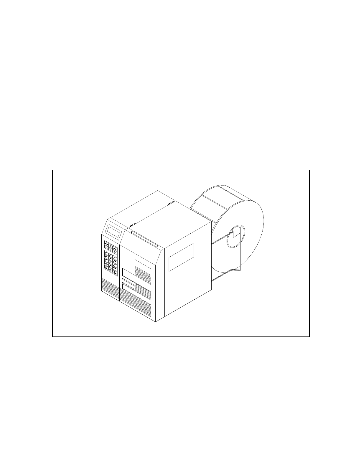
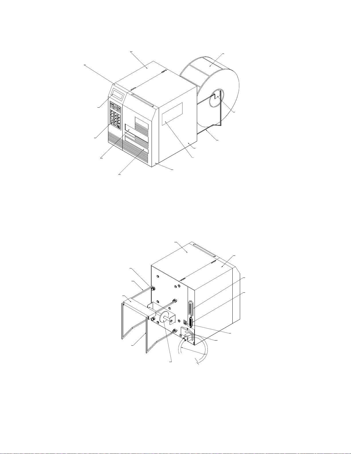
LEFT SIDE FRONT PANEL
DISPLAY
KEYPAD
PAPER SLOT
LEFT SIDE COVER
BACKING PAPER SLOT
PAPER SUPPLY
PAPER SUPPLY HOLDER
PAPER SUPPLY RACK
RIGHT SIDE COVER
RIBBON VIEW WINDOW
RIGHT SIDE FRONT PANEL
Microcom 470 Printer
Front View
Figure 1
RACK THUMB SCREW
LEFT PAPER SUPPLY RACK
PAPER SUPPLY HOLDER
RIGHT PAPER SUPPLY RACK
RIGHT SIDE COVER
LEFT SIDE COVER
PARALLEL PORT
SERIAL PORT
POWER SWITCH
POWER ENTRY MODULE
POWER CORD
PAPER LINE GUIDE
Microcom 470 Printer
Rear View
Figure 2
))))))))))))))))))))))))))))))))))))))))))))
6
470 Operators Manual
Page 15
CHAPTER 2: BASIC OPERATION
2.1 UNPACKING THE 470 PRINTER
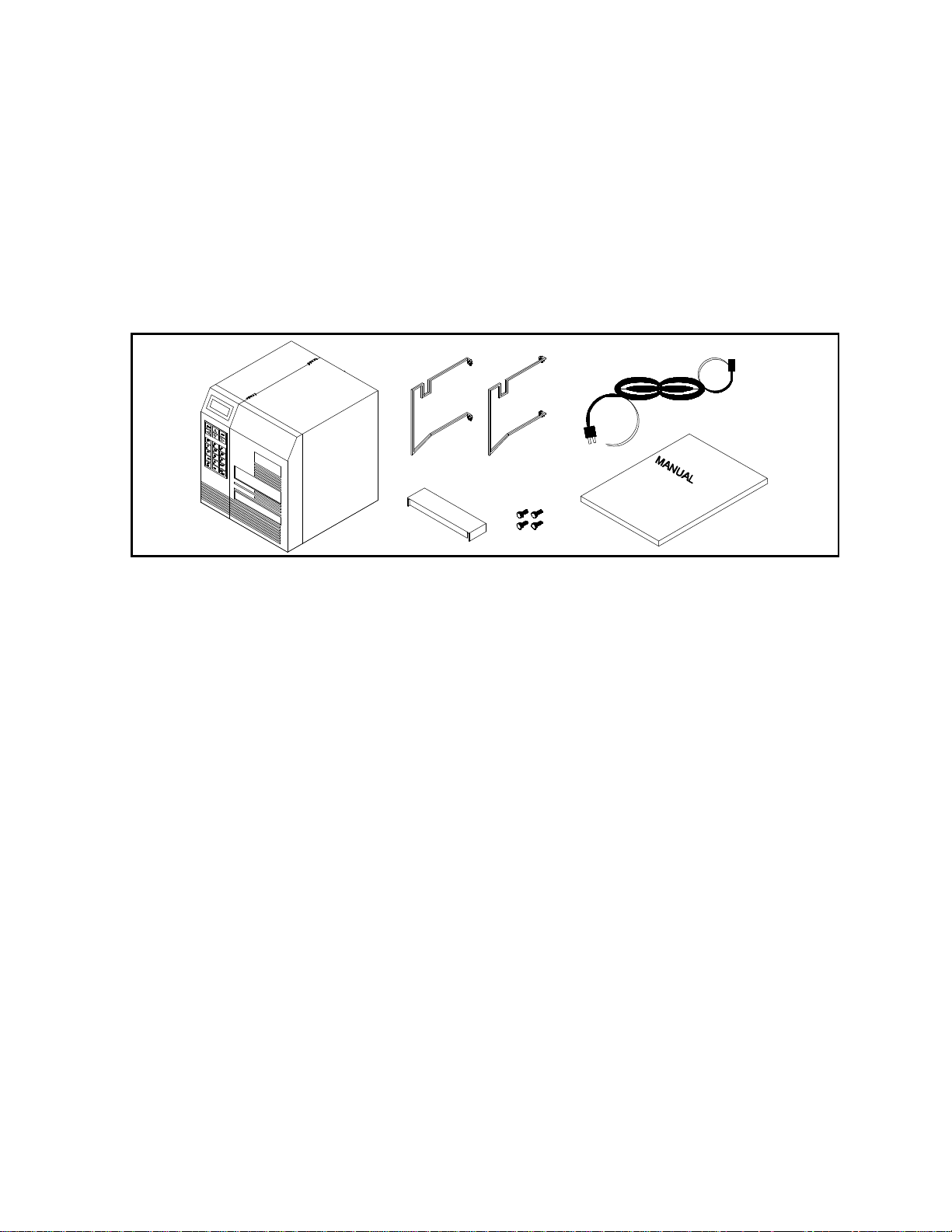
While unpacking the printer, please check all packing materials closely to avoid misplacing any
necessary parts. After the printer is removed from the box, verify that all parts are present and
in good condition (see Figure 3). All packaging material should be kept and used if the printer
is to be shipped. The printer must be returned in the original container to insure proper
warranty coverage.
Printer Parts figure 3
2.2 MOUNTING THE LABEL SUPPLY RACKS
Position the printer so that the rear is assessable. Refer to Figure 2 and note the mounting
positions of each rack. Notice that the bent flanges point inward. Using the thumbscrews
provided, attach the racks to the printer.
2.3 INITIAL POWER UP
Before connecting the printer to a power source, verify that the voltage selector, located on the
rear of the printer, is set correctly. If not, open the selection door and rotate the cylinder until
the correct voltage is shown.
Plug the printer in and turn the power switch on. The back lighted LCD should illuminate and
temporarily display 'ASSUMING DIRECT THERMAL' or 'ASSUMING THERMAL TRANSFER'. If
this does not occur, check the power source and if necessary call your service organization.
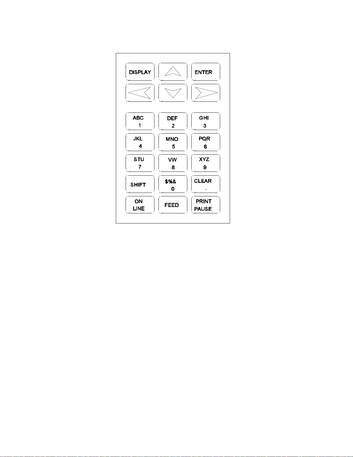
2.4 FRONT PANEL KEYPAD AND STATUS DISPLAY
The front panel contains a 21-key, alphanumeric, keypad and a two-line, back lighted, LCD
display. Through the use of the keypad and display, many printer commands can be directly
entered or modified.
))))))))))))))))))))))))))))))))))))))))))))
470 Operators Manual
7
Page 16
Basic Operation Chapter 2
))))))))))))))))))))))))))))))))))))))))))))
Keypad Layout
Figure 4
2.4.1 PRINT/PAUSE KEY
The front panel keypad (see Figure 4) contains a label 'PRINT/PAUSE' key. If this key is
pressed the unit will print the currently loaded label format or the default label if no format has
been loaded. If the printer is in the process of printing a predetermined quantity of labels (see
^D73, section 5.3), pressing the 'PRINT/PAUSE' key will pause the printer. Pressing the key
again will allow the printer to continue the batch.
If the 'PRINT/PAUSE' key is depressed when the power is turned on, the printer is put into test
mode and a statistics and test label will be printed (see ^D29 chapter 5.3.10).
2.4.2 FEED KEY
Pressing and holding the 'FEED' key will cause the printer to advance until released. This key
can be use to load and align paper stock.
))))))))))))))))))))))))))))))))))))))))))))
8
470 Operators Manual
Page 17

Chapter 2 Basic Operation
))))))))))))))))))))))))))))))))))))))))))))
2.4.3 ON-LINE KEY
Pressing the 'ON-LINE' key causes the printer to suspend the processing of characters
through the communication ports and display the message OFF-LINE. If a character is sent to
the printer when communicating serially, the printer will accept the character and send an XOFF (assuming X-OFF has been enabled). The printer will continue to receive characters until
the buffer is full, at which time any further characters will be ignored. The Clear to Send signal
is always low when OFF-LINE.
2.4.4 ALPHA-NUMERIC KEYS
The Alpha Numeric keys are used to modify formats and input variable data into the printer.
The unshifted characters are 0 through 9 and the period. The shift key is pressed once for the
characters ADGJMPSVX$ and the clear key, twice for BEHKNQTWZ%, and three times for
CFILORUZ&.
))))))))))))))))))))))))))))))))))))))))))))
470 Operators Manual
9
Page 18
Basic Operation Chapter 2
))))))))))))))))))))))))))))))))))))))))))))
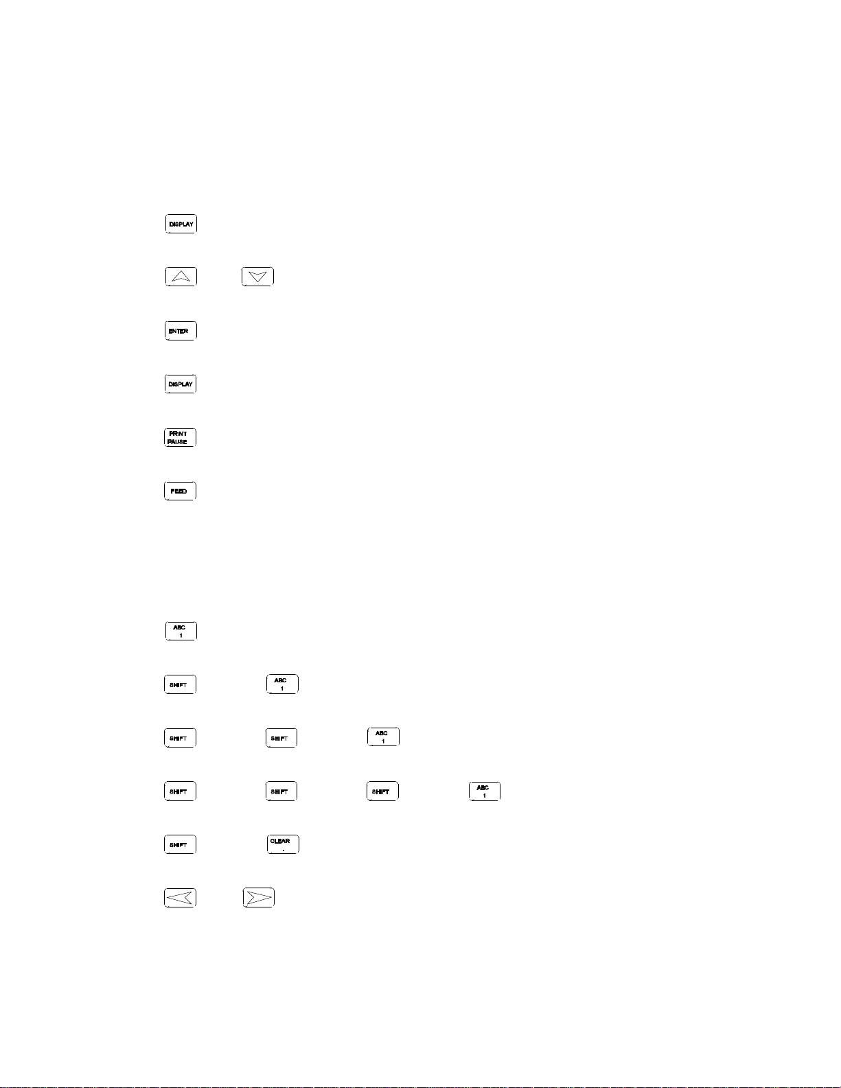
2.5 MENU OPERATION
General Operation
Press to access the menu screen.
Press or to scroll through options.
Press to accept current option.
Press to exit/cancel current menu/option.
Press to print current label.
Press to advance paper and ribbon (if in transfer mode).
Variable Data Entry
Press to input a 1.
Press then to input an A.
Press then then to input a B.
Press then then then to input a C.
Press then to input a space.
Press or to scroll left or right through entry.
))))))))))))))))))))))))))))))))))))))))))))
10
470 Operators Manual
Page 19

Chapter 2 Basic Operation
))))))))))))))))))))))))))))))))))))))))))))
2.6 LOADING MEDIA
The following two sections explain the dispensing modes and printing methods. Refer to
figures 2 and 5 for the printer components. If narrow stock is used (3.5 inches wide or less), it
may be necessary to adjust the printhead support screw (see section 2.8).
Thermal Transfer Note:
The 470 will, on power-up, automatically sense a loaded ribbon and select thermal transfer
mode. Please note that the printer will not select thermal transfer mode if the ribbon is loaded
after the printer is turned on. To correct the situation simply cycle the power once the ribbon
has been loaded.
2.6.1 NORMAL AND TAG/TEAR MODES
Place the label supply shaft and stock onto the wire rack. Raise the print head with the lift lever
and insert the paper with the thermally sensitive side up. Follow the loading diagram and
thread the paper through the printer and under the print head. Lower the head lift lever and
you are ready to print.
2.6.2 PEEL-AND-DISPENSE MODE
Follow the paper loading in the normal and tag mode directions. Pull out several inches of
paper and remove the labels. Be sure the leading edge of the stock is flat and square. Rotate
the pinch roller release knob and insert the paper between the black drive roller and the white
pinch roller. Remove the slack and release the pressure on the pinch roller by turning the
release knob.
Printer Feed Mechanism
Figure 5
))))))))))))))))))))))))))))))))))))))))))))
470 Operators Manual
11
Page 20

Basic Operation Chapter 2
))))))))))))))))))))))))))))))))))))))))))))
2.7 RIBBON SELECTION
Many different ribbons can be used with the 470. However, to extend printhead life and
achieve quality results, it is necessary to correctly match the ribbon to the receiver stock.
Incorrect matching can cause premature printhead failure. Please contact Microcom
concerning recommended media and compatibility.
2.8 PRINTHEAD SUPPORT ADJUSTMENT
When using narrow media, less than 3.5" wide, it is possible to increase print quality and
prevent premature drive roller wear by correctly adjusting the printhead support screw. To
make the adjustment, simply turn the head adjustment screw (see figure 5) clockwise until the
printhead is slightly lifted from the drive roller. Once the head has been lifted from the roller,
verify that the print head has not been lifted too far by printing a test label. If the print quality
on the right side of the label appears weak, then lower the printhead by turning the thumb
screw counter clockwise until the print quality is corrected. If the quality problem appears on
the left side, turn the screw clockwise until the print quality is corrected.
2.9 CLEANING INSTRUCTIONS
The 470 printer and printhead should be cleaned approximately every 7,500 inches or every
two weeks whichever occurs first. The printer should also be cleaned whenever you run out of
label stock. Proper cleaning assures that any adhesive that may come off the end of the
previous roll, is removed. A Microcom cleaning kit (part #040005) should be used for cleaning
and maintaining a Microcom printer product. It is important to note that optimum printhead life
is achieved by cleaning the printer and printhead.
To clean your Microcom 470 printer:
1) Turn the printer off.
2) Lift the printhead using the lift lever at the rear of the printer and remove any label
stock that remains inside the head mechanism.
3) Using the cleaning brush, sweep away all small label and adhesive particles that may
be in the area of the printhead.
4) Moisten a cleaning swab with the cleaning solution and wipe away any adhesive from
the rollers or the aluminum peel bar.
5) Dampen a swab with cleaning solution and lift the print head. Take the moistened swab
and gently wipe the underside of the printhead. Repeat if necessary (if swab is
extremely dirty).
6) Moisten the felt side of a cleaning card with the cleaning solution. Raise the print head
and insert the cleaning card under print head with the felt side facing up. Lower the
print head and press the feed key to feed the card through the printer. Allow the
printhead to ride on the cleaning card. Repeat the process if needed. The cleaning card
may be used once at each end.
WARNING: DO NOT TOUCH THE PRINTHEAD WITH ANY METAL OR SHARP OBJECTS
))))))))))))))))))))))))))))))))))))))))))))
12
470 Operators Manual
Page 21
CHAPTER 3: COMMUNICATIONS
The 470 is very versatile. It can be interfaced to PC's, mini-computers, main frames, and
special purpose machines. It is capable of serial RS-232-C, Centronics® parallel, and
optionally RS-422/485 serial communication. The following sections explain the communication
interfaces.
Out of the box, unless otherwise requested, the Microcom 470 communicates using serial RS232-C at 9600 baud, 8 data bits, 1 stop bit and no parity with both hardware and software
handshaking. This configuration may be changed as shown in Appendix E.
3.1 CABLE PINOUT
Table 1 shows the signals of the 470's 25-pin RS-232 serial port and table 2 shows the parallel
port configuration.
If serial RS-232-C communication is selected and XON/XOFF hand shaking is used, the only
signals the 470 requires are the RXD, TXD, and GND signals. If hardware (CTS) hand shaking
is used, a CTS signal is provided and an RTS signal is required. XON/XOFF may be disabled
through software dip switch #1 (see chapter 5). The other signals are offered in the event the
host computer requires these signals.
Serial Port Configuration
25 TO 9 PIN 25 TO 25 PIN
State 470 Direction PC
HI 8 DCD---->---- DCD 1
XX 3 TXD---->---- RXD 2
XX 2 RXD----<---- TXD 3
HI 20 DTR---->---- DSR 4
LO 7 GND—<->--- GND 5
HI 6 DSR---->---- DTR 6
DC 4 RTS----<---- CTS 7
XX 5 CTS---->---- RTS 8
HI 18 5V
DB-25 DE-9
DC = Do Not Care
XX = Indeterminate
State 470 Direction PC
XX 3 TXD---->---- RXD 3
XX 2 RXD----<---- TXD 2
HI 20 DTR---->---- DSR 6-8
LO 7 GND—<->--- GND 7
HI 6-8 DSR---->---- DTR 20
DC 4 RTS----<---- CTS 4
XX 5 CTS---->---- RTS 5
HI 18 +5V---->---- +5V 18
DB-25 DB-25
DC = Do Not Care
XX = Indeterminate
Table 1
))))))))))))))))))))))))))))))))))))))))))))
470 Operators Manual
13
Page 22
Communications Chapter 3
))))))))))))))))))))))))))))))))))))))))))))
Parallel Port Configuration
1 = /STROBE
2 = D0
3 = D1
4 = D2
5 = D3
6 = D4
7 = D5
8 = D6
9 = D7
10 = /ACK
11 = BUSY
12 = PAPER OUT
13 = SCLT
14 = NC
15 = NC
16 = LOGIC GND
17-18 = NC
19-30 = LOGIC GND
31 = /INIT
32 = /ERROR
33 = LOGIC GND
34-36 = NC
(36 PIN CENTRONICS®)
Table 2
3.2 PRINTER CABLES
For parallel connection: Use a standard 36 pin male Centronics® to 25 pin male cable,
connected from the desired parallel port of the host computer to
the 36 pin connector on the 470.
For serial connection: If your host computer has a...
9 pin serial com port - Use a 9 pin female to 9 pin male video extension cable. (pin #1 to
pin #1...)
25 pin serial com port - Use a standard 25 pin male to 9 pin male serial cable.
Note: NULL modem cable adapters are not necessary since the printer is DCE equipment.
))))))))))))))))))))))))))))))))))))))))))))
14
470 Operators Manual
Page 23

CHAPTER 4: DESIGNING LABELS USING LDS
Label Design Software (LDS) refers to the software resident in the printer used to decipher
label formats sent by the host computer. All fonts, character sets and bar codes symbologies
are resident in the printer.
A label format is produced by a series of 5 steps:
1: Control commands to define printer operation
2: A header to define label height, width, print speed, etc..
3: Field data to define placement of text, bar code, graphic or line
4: Actual text data to place in the above text or bar code fields
5: Control commands to initiate printing
4.1 CONTROL CHARACTERS
Throughout this manual there are references to control characters. In order to print them in this
manual, they have been written using standard characters and icons. Escape characters are
represented by <ESC> and a carriage return is represented by the 5 symbol. It is important to
note that all printer functions, unless otherwise noted, must be followed with a carriage
return5.
4.2 GETTING STARTED
There are many different machines that can send information to the 470 printer: For example main frames, mini-computers, special purpose computers and PC's. However, if you are using
the printer for the first time, the easiest way to start is with a PC and a terminal emulation
software program. This will allow two-way, serial communication with the printer. You will be
able to quickly upload files and access label-sizing and other features that will help
considerably in formatting your first labels.
4.2.1 PC CONNECTION (SERIAL)
Items required:
- A computer with at least one unused serial communications port. (COM1,COM2...)
- A serial interface cable. (See section 3.2 for cable information)
- A terminal emulation program. (Procomm, Telix, Windows terminal...)
Note: This communications test assumes that you have a standard serial 470 printer.
Set the communication parameters in the PC terminal software program to 9600 baud, no
parity, 8 data bits and 1 stop bit. Unless modified by the user, this is the printers'
communication configuration out of the box. Depress ^C (ASCII or control code) on the PC
keyboard. If the printer prints a label, proper PC to printer communications have been
confirmed. Depress ^E to verify printer to PC communication. You will receive a text response
from the printer.
If a terminal program is not available, it is possible to send files to the printer using the DOS
COPY command. To do this you must first create a text file containing the information to be
sent (i.e. ^C ). You may use any text editor that does not add its own formatting characters
(QEDIT, Wordstar non-document mode, DOS 5.0 EDIT, EDLIN...).
))))))))))))))))))))))))))))))))))))))))))))
470 Operators Manual
15
Page 24

Designing Labels Using LDS Chapter 4
))))))))))))))))))))))))))))))))))))))))))))
Use the following DOS MODE command to set up the appropriate PC port.
Note: COM1 may be any available communications port on your PC.
C:>MODE COM1:9600,N,8,1,P
You must then send the file to the printer using the following DOS command.
C:>COPY FILENAME COM1
4.2.2 PC CONNECTION (PARALLEL)
Items required:
- A computer with at least one unused parallel communications port. (LPT1,LPT2...)
- A parallel interface cable. (See section 3.2 for cable information)
Create a text file containing the information to be sent. (^C is the print command.)
^C
You may use any text editor that does not add its own formatting characters (QEDIT, Wordstar
non-document mode, DOS 5.0 EDIT, EDLIN...). Send the file to the printer using the following
DOS command. Note: LPT1 may be any available printer port on your PC.
C:>COPY FILENAME LPT1
4.2.3 LEARNING LDS
You can test some of the control code functions (see section 5.1) directly through the
keyboard. Large label files, such as some of those illustrated in Appendix B, may be entered in
a straight ASCII text word editor and then up-loaded to the printer using a terminal emulation
program or the DOS copy command. (To use the DOS copy command, first use the DOS
mode instruction to configure the PC. For example, MODE COM1:9600,N,8,1,P).
There are some special features offered by the 470 printer that will aid in label design. For
example, the autosize command (^A2^D395) will provide most of the header format
information needed to define the different properties of label stock. The state of the machine is
accessed through the enquiry command (^D55 or ^E). The statistical printer information is
made available through the ^A0^D295 command.
The following sections of this chapter are designed to give an overview of a label format,
define the label header, and list the different types of field information available. Chapter 5
explains the special functions of the control codes. Once some understanding of these basic
concepts are achieved, use the quick reference guide in Appendix D for expedient label
design.
4.3 FORMATTING LABELS: AN OVERVIEW
A label format consists of a header record and field records, followed by the text data to be
printed. The records describe how the label is to be printed. The header contains information
about the label itself such as label height, width, print speed, etc. The field records refer to the
))))))))))))))))))))))))))))))))))))))))))))
16
470 Operators Manual
Page 25
Chapter 4 Designing Labels Using LDS
))))))))))))))))))))))))))))))))))))))))))))
data section and contain information about positioning coordinates, the type of character
generators or bar codes to use, etc.. Below is a sample label format. We will refer to this
format as we break down the components of its structure.
(See Figure 6)
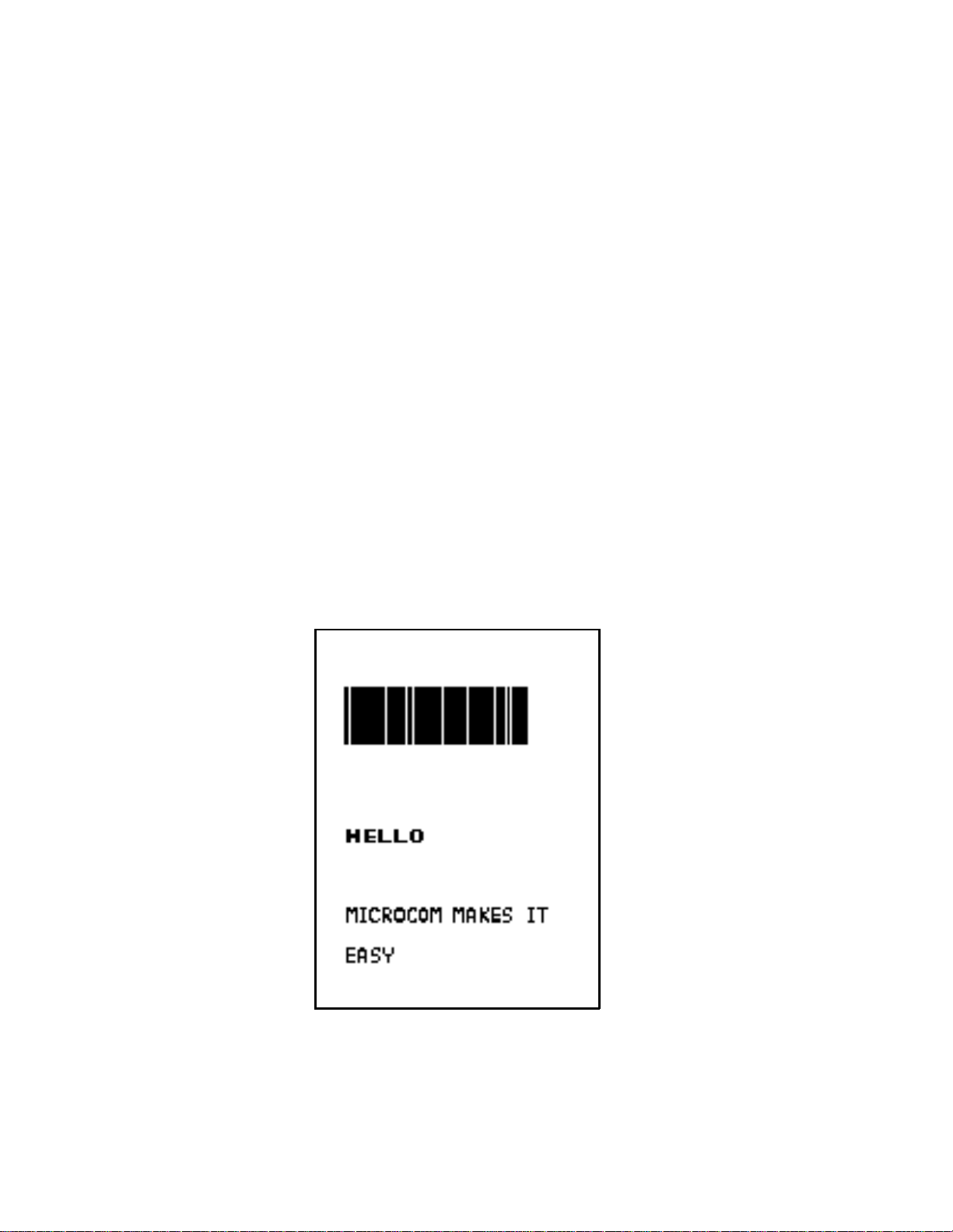
^D575
4,812,609,,205
1,100, 40, 4, 1,45
2,100, 60,17, 1,45
3,100,100, 5, 1,65
3,100,150, 5,16,2,,,,305
^D565
^D25
EASY5
MICROCOM MAKES IT5
HELLO5
^D35
A label format is coming
Header information
Field #1 information
Field #2 information
Field #3 information
Field #4 information
Select RAM Format
Text Data is Coming
Text String #1
Text String #2
Text String #3
Print Label 1
Microcom Label
Figure 6
))))))))))))))))))))))))))))))))))))))))))))
470 Operators Manual
17
Page 26

Designing Labels Using LDS Chapter 4
))))))))))))))))))))))))))))))))))))))))))))
The sequence ^D575 puts the printer in format entry mode.
The next line is the header information: sizing the label (812 dots wide 609 dots high).
The next four lines are layout information for each data field in the format.
The sequence ^D565 selects the user layout.
The sequence ^D25 tells the printer to start accepting data for each defined field. (Field #1
defines where Data #1 should be positioned.)
(Note: The label prints from bottom to top.)
The next three lines are data for each field.
Text string #3 is accessed twice. The format will print the word 'EASY' and then the bar code
equivalent.
The sequence ^D35 starts the print cycle. (Default is one copy. See section 5.3.2)
4.4 LABEL HEADER
The header consist of eleven parameters. These parameters contain information about the
label. It is not necessary to enter information for all of the parameters: If a parameter is left
blank, then the default value will be used. A carriage return must follow the label header
parameters.
The value of measurement for many of the header elements is the dot. There are 203 dots per
inch on a 470 print head (8 dots/mm). There is a maximum 832 dots in the X direction (width).
The Y direction (length) is 4060 dots or 20 inches long. (The print length is virtually unlimited in
Epson® mode ).
Most header parameters can be supplied using the autosize command. (See section 5.3.3.)
Below is a list of the header element mnemonics and their default values:
HFM, LSX, LSY, WEB, GAP, DPS, LCB, AGD, SPG, OFX, OFY
0, 832, 443, 10, 10, 48, 0, 1, 535, 0, 0
))))))))))))))))))))))))))))))))))))))))))))
18
470 Operators Manual
Page 27
Chapter 4 Designing Labels Using LDS
))))))))))))))))))))))))))))))))))))))))))))
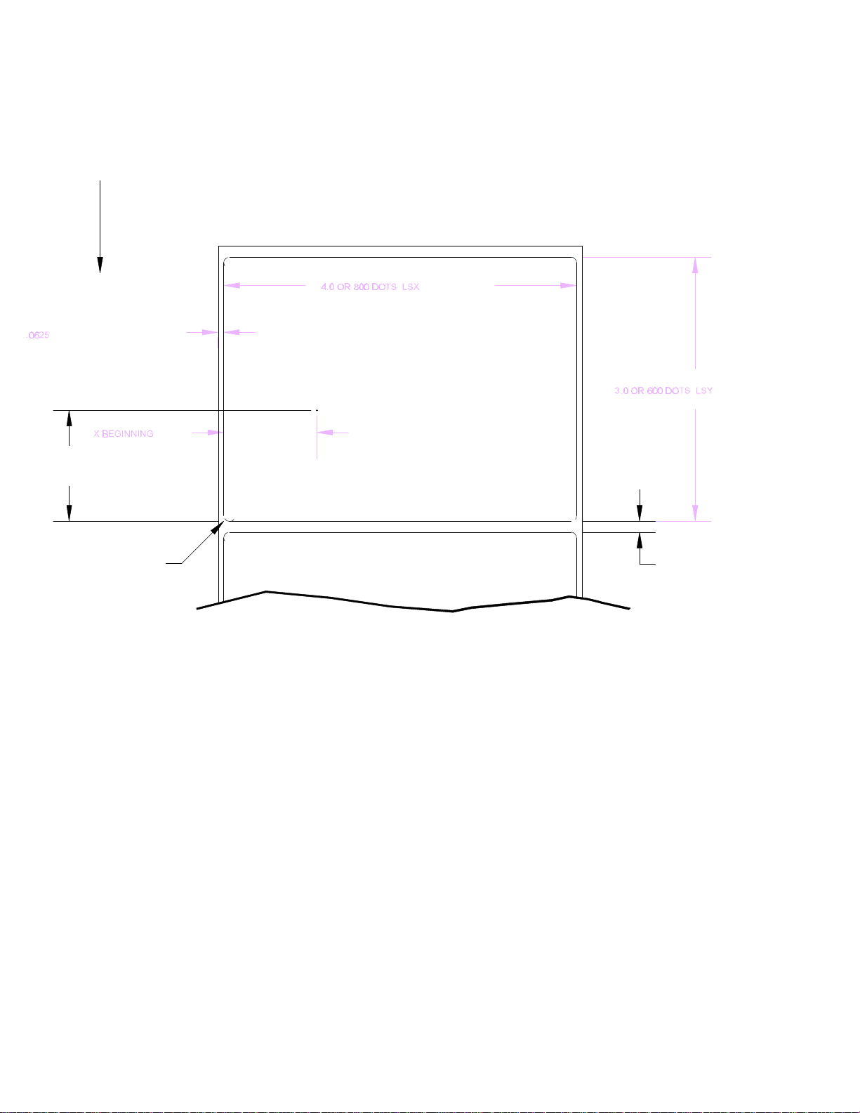
FEED DIRECTION
OR 12 DOTS
THIS IS THE WEB VALUE
Y BEGINNING
MICROCOM
THIS IS 0,0
Label Header Parameters of a 4" X 3" Label
Figure 7
OR 25 DOTS
.125
THIS IS THE GAP VALUE
))))))))))))))))))))))))))))))))))))))))))))
470 Operators Manual
19
Page 28

Designing Labels Using LDS Chapter 4
))))))))))))))))))))))))))))))))))))))))))))
Refer to Figure 7 for a visual representation of most header parameters.
The following is a description of each header element:
HFM NUMBER OF FIELDS IN LAYOUT
This parameter is used to specify the number of fields in the layout. If more fields are
defined than what is specified for HFM, the extras will be ignored. To prevent software
confusion, do not set the HFM parameter to a number higher than the number of fields
defined.
LSX LABEL SIZE X DIRECTION
Specifies the width of the label in dots. For example: A 3" wide label would have an
LSX of 3 x 203 = 609 dots. (203 dots = 1 inch)
LSY LABEL SIZE Y DIRECTION
Specifies the height of the label in dots. (maximum of 4020 dots)
WEB WEB SIZE
The width, measured in dots, of the webbing that is found on the left side of the label.
GAP GAP SIZE
The height, measured in dots, of the gap between labels. Autosizing (See section
5.3.3) will define this value.
DPS PRINT SPEED
The speed the printer prints a label. Generally, better print quality is obtained at lower
print speeds.
The labels per minute a particular format will print can be calculated by the equation
below:
IPS x 60 seconds
Labels per Minute = -------------------------- Label Height
The printer's default print speed is 3.2 inches per second (DPS value = 48). To speed it
up or slow it down, the following DPS parameters can be inserted into the label header.
Note that a higher value slows the printer down and a smaller value speeds it up.
See Table 3 for a list of print speeds, DPS values, and inches per second.
))))))))))))))))))))))))))))))))))))))))))))
20
470 Operators Manual
Page 29
Chapter 4 Designing Labels Using LDS
))))))))))))))))))))))))))))))))))))))))))))
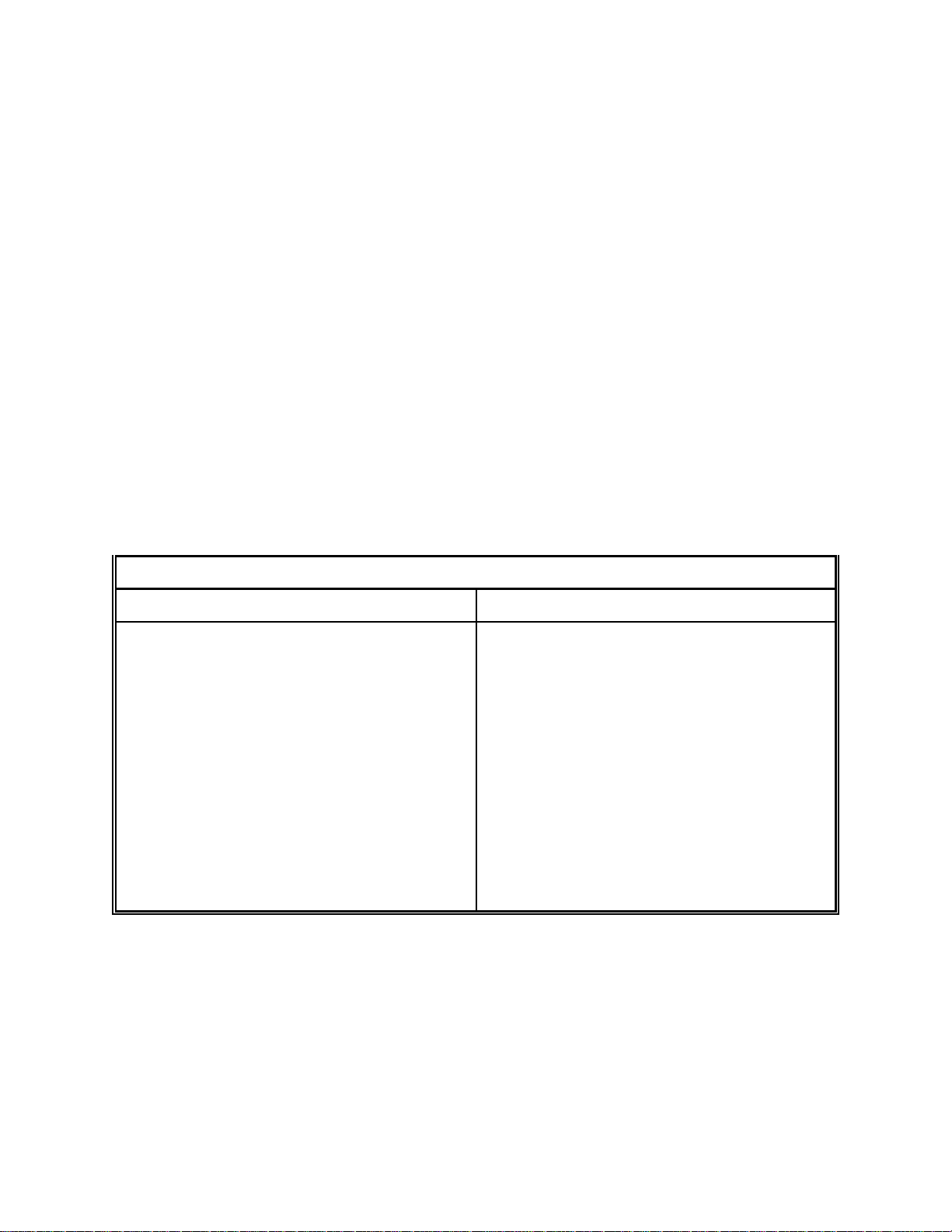
Print Speed
DPS VALUE MM PER SECOND INCHES PER SECOND INCHES PER MINUTE
0
1
2
3
4
5
6
7
8
9
10
11
12
13
14
15
16
17
18
19
20
21
22
23
24
25
26
27
28
29
30
31
32
33
34
35
36
37
38
39
40
41
42
43
44
45
46
47
48
49
50
51
52
53
54
55
56
57
58
59
60
203.2
200.7
198.1
195.6
193.0
190.5
188.0
185.4
182.9
180.3
177.8
175.3
172.7
170.2
167.6
165.1
162.6
160.0
157.5
154.9
152.4
149.9
147.3
144.8
142.2
139.7
137.2
134.6
132.1
129.5
127.0
124.5
121.9
119.4
116.8
114.3
111.8
109.2
106.7
104.1
101.6
99.1
96.5
94.0
91.4
88.9
86.4
83.8
81.3
78.7
76.2
73.7
71.7
68.6
66.0
63.5
61.0
58.4
55.9
53.3
50.8
8.0
7.9
7.8
7.7
7.6
7.5
7.4
7.3
7.2
7.1
7.0
6.9
6.8
6.7
6.6
6.5
6.4
6.3
6.2
6.1
6.0
5.9
5.8
5.7
5.6
5.5
5.4
5.3
5.2
5.1
5.0
4.9
4.8
4.7
4.6
4.5
4.4
4.3
4.2
4.1
4.0
3.9
3.8
3.7
3.6
3.5
3.4
3.3
3.2
3.1
3.0
2.9
2.8
2.7
2.6
2.5
2.4
2.3
2.2
2.1
2.0
480
474
468
462
456
450
440
438
432
426
420
414
408
402
396
390
384
378
372
366
360
354
348
342
336
330
324
318
312
306
300
294
288
282
276
270
264
258
252
246
240
234
228
222
216
204
204
198
192
186
180
174
168
162
156
150
144
138
132
126
120
Table 3
))))))))))))))))))))))))))))))))))))))))))))
470 Operators Manual
21
Page 30

Designing Labels Using LDS Chapter 4
))))))))))))))))))))))))))))))))))))))))))))
LCB LABEL CONTROL BYTE
This parameter selects between the various gap detection methods.
Continuous Stock: If set to a value of 2, the printer will not activate the gap detector
circuit. After all fields are printed, the printer will advance the extra distance in the SPG
header element.
Normal Stock (leading edge): If set to a value of 0, the printer will detect the leading
edge of the label (the start of the next label).
Black Line Stock: If set to a value of 1, the printer will detect the leading edge of a black
line.
Blow Hole Stock (Slot-Cut): If set to a value of 0, the printer will detect the leading edge
of a blow hole (see software dip switch #4 (^D24) for blow hole stock).
AGD NUMBER OF STEPS TO ACTIVATE GAP DETECTOR
This parameter selects the number of steps (dots) that the printer should skip before
gap sensing is activated. This value is usually defaulted. It is not defaulted when using
stock that contains pre-print or gaps that may cause the gap detector to trigger
incorrectly.
SPG NUMBER OF STEPS PAST GAP
The number of steps to advance the label after detection of a label gap. Use autosizing
(See section 5.3.3) to quickly evaluate this parameter for small stock.
It may also be necessary to adjust this value if using material with a sense position not
located at the end of the stock.
The 470 uses the following formula to determine the SPG setting:
If label height is greater than or equal to 580, then SPG=580
If label height is less than 580, subtract (LSY+GAP) from 580 until the answer is
negative, then add (LSY+GAP) back to become positive again. Subtract the AGD value
(usually 1) and the result will be the correct SPG.
OFX X DIRECTION OFFSET
This parameter moves all the fields in the X direction without changing the fields
themselves.
OFY Y DIRECTION OFFSET
This parameter moves all the fields in the Y direction without changing the fields
themselves.
))))))))))))))))))))))))))))))))))))))))))))
22
470 Operators Manual
Page 31

Chapter 4 Designing Labels Using LDS
))))))))))))))))))))))))))))))))))))))))))))
4.4.1 A SAMPLE SESSION (HEADER)
This is the label header from the sample label in section 4.3.
4,812,609,,20,48,,,55
4 - 4 fields following the header
812 - Label width (LSX) of 812 (812/203 = 4 inches).
609 - Label length (LSY) of 406 (609/203 = 3 inches).
- The WEB parameter can be defaulted.
20 - A GAP between labels of 20 (20/203 = 0.10 inch).
48 - Label print speed (DPS) of 48 = 3.2 inches per
second (from Table 3)
- No entry for the LCB parameter means default value
of 0, normal stock on backing paper.
- The AGD could be defaulted. This value was
confirmed using the autosize command.
- SPG could be defaulted. This value was confirmed
using the auto-size function.
55 - A carriage return must follow the label header. There
were two parameters left that were not entered into the
header - OFX and OFY. Because they were not entered,
the printer assumes the default values, 0 in their
cases. Likewise, since the AGD and SPG were defaulted,
the carriage return could have followed the DPS.
Note: Defaulted fields must be separated by commas.
))))))))))))))))))))))))))))))))))))))))))))
470 Operators Manual
23
Page 32

Designing Labels Using LDS Chapter 4
))))))))))))))))))))))))))))))))))))))))))))
4.5 LABEL FIELDS
A field is broken down into many different parameters. These parameters contain the
information necessary to position data (text, bar codes, graphics, etc.) on the label. It is
not necessary to enter values for all of the field parameters; the default values will be
used if left blank. The fields to be defaulted must be separated by commas. A carriage
return must follow each label field.
4.5.1 BIT MAPPED TEXT AND Bar code FIELDS
The following is a list of bit mapped (ROM stored and Downloaded) field element
mnemonics and their default values:
TSN, XB, YB, CC,TCI,CGN, FO, FJ, CMX,CMY, CS, TSP, AN, PS
1, 0, 0, *, 1, **,***, 0, 1, 1, *, 1, 0, 0
* The default depends on the character generator (CGN) used.
** The default depends on the TCI used.
*** The default for circular bar codes is 80. Everything else is 0.
Note: All values must be positive integers.
TSN TEXT STRING NUMBER
Determines from which text string the field obtains the data. This allows for more than
one field to use the same text string. A TSN of 0 accesses the clock chip text string
(see section 5.3.4). A TSN of 1 accesses the first line of data. A TSN of 2 accesses the
second line of data, and so forth. Data is the text that follows a ^D25 command in a
label layout.
XB X BEGINNING COORDINATE
The X coordinate of the field is measured in dots. The far left edge of the label as
viewed from the front of the printer is X coordinate 1. There is no X coordinate 0. The X
coordinate increases in size from left to right (See Figure 7). An XB of 203 would place
the text one inch from the left side of the label.
YB Y BEGINNING COORDINATE
The Y coordinate of the field is measured in dots. A YB of 1 would be specified as the
first edge of the label coming out of the front of the printer during a label print. The Y
coordinate increases in size from the bottom to the top of the label (See Figure 7). A
YB of 203 would place text one inch from the bottom of the label.
))))))))))))))))))))))))))))))))))))))))))))
24
470 Operators Manual
Page 33

Chapter 4 Designing Labels Using LDS
))))))))))))))))))))))))))))))))))))))))))))
CC CHARACTER COUNT
This parameter determines the number of characters that will be used in a field. If the
number of characters in the selected text string is more than the quantity specified by
CC, then the remainder of the text string is ignored. If the text string has less than the
number of characters specified by this parameter, then only those characters defined
by the text string are printed. For example, the text string - MICROCOM - would be 8
characters long.
TCI TEXT CONVERSION IDENTIFIER
This parameter determines what form the text string will be printed in. The following
values define which text conversion method is used:
1 Text (ASCII)
2 Text Surrounded by Asterisks (Code 3 of 9)
3 Text with UPC-A/UPC-E Checksum Digit Printed
8 Non-Volatile Downloadable Fonts
11 Volatile Downloadable Fonts
12 UPC-A Bar code
13 UPC-E Bar code (SEND 11 DIGITS)
14 UPC-E Bar code (SEND 7 DIGITS)
15 Interleaved 2 of 5 Bar code
16 Code 3 of 9 Bar code
*17 Text with UPC-E Checksum and Extended Bars Added
20 EAN-13 Bar code
21 EAN-8 Bar code
*22 Text with EAN-13 Checksum and Extended Bars Added
*23 Text with EAN-8 Checksum and Extended Bars Added
24 MSI 1 (Plessey)
25 MSI 2 (Plessey)
26 MSI 3 (Plessey)
*28 Text with MSI Checksum Added - Type 1
*29 Text with MSI Checksum Added - Type 2
*32 Text with UPC-A Checksum and Extended Bars Added
*33 Text with UPC-A With Extended Bars Added
36 Postnet
40 Code 128 bar code (Automatic Compression)
41 Code 128 bar code (No Compression)
42 Codabar bar code
43 Code 93 bar code
44 AS-10 bar code
* Refer to Section 7.1.1 on how to use these TCI's.
Example: For the string - 1234567
A TCI of 1 would print ASCII text.
A TCI of 42 would print a Codabar bar code.
))))))))))))))))))))))))))))))))))))))))))))
470 Operators Manual
25
Page 34

Designing Labels Using LDS Chapter 4
))))))))))))))))))))))))))))))))))))))))))))
CGN CHARACTER GENERATOR NUMBER
This refers to the character generator (font size, bar code size, etc.) that is used.
The generator numbers and the specifications for the various fonts, bar codes, and
graphics are shown below. Remember, there are 203 dots per inch.
Key For Tables:
CGN - Character Generator Number
FO - Field Orientation
Height - Y Direction, in Dots
Width - X Direction, in Dots
Spacing - Default Spacing Between Characters, in Dots
Font Type - Font Descriptor
'-' - Not Used
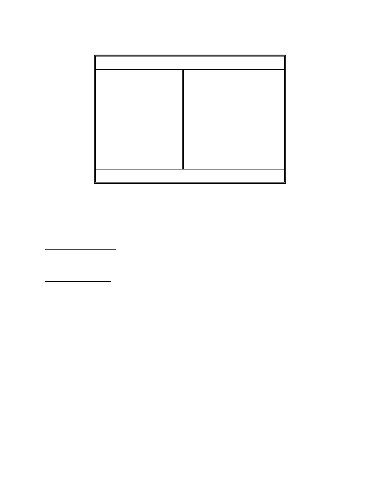
Bitmapped Font Descriptions
CGN Height Decender Width Spacing Font Type
1
2
3
4
5
6
7
8
9
10
11
12
13
14
15
16
5
7
7
9
9
12
16
15
18
19
19
27
27
38
38
40
9
-
12
15
20
25
25
35
35
30
30
-
Table 4
3
5
7
5
7
9
10
12
10
15
15
21
21
30
30
20
1
1
1
1
2
2
2
2
2
3
3
3
3
3
4
4
Standard
Lower Case
Bold
Standard
Lower Case
Lower Case
OCR-A
Lower Case
Standard
Lower Case
Lower/Bold
Lower Case
Lower/Thin
Lower/Fancy
Lower/Bold
Standard
))))))))))))))))))))))))))))))))))))))))))))
26
470 Operators Manual
Page 35

Chapter 4 Designing Labels Using LDS
))))))))))))))))))))))))))))))))))))))))))))
Table 5 constitutes the bar codes available on the 470 printer. Some bar codes offer different
ratios to accommodate different applications. See Section 7.1 for more information on
designing with bar codes.
Bar code Symbologies
Bar code CGN Ratio Height Spacing FO
Code 3 of 9
I 2 of 5
*UPC/EAN
*UPC Readable
*Code 128
Codabar
Code 93
AS-10
MSI (Plessy)
* These bar codes must be multiplied by 2 for a 80% ratio.
FO FIELD ORIENTATION
This parameter defines the rotation of each field on the label. The point of rotation is
determined from the field justification. (If referencing a circular bar code field, this
parameter is used to define the inside white space diameter of the bar code.)
2
3
4
2
3
5
-
-
2
3
-
-
-
2:1
3:1
3:1 wide
2:1
3:1
5:2
40%
40%
40%
2:1
3:1
2:1
2:1
1:1
Table 5
1
1
1
1
1
1
1
1
1
1
1
1
1
1
-
-
-
-
-
-
-
-
-
-
-
-
-
-
0123
0123
0123
0123
0123
0123
0123
0123
0123
0123
0123
0123
0123
0123
0 0 degrees (normal rotation).
90 90 degrees (left rotation).
180 180 degrees (upside-down rotation).
270 270 degrees (right rotation).
FJ FIELD JUSTIFICATION
This parameter defines the justification of each field on the label.
0 Left justified above base-line.
1 Right justified above base-line.
2 Left justified below base-line.
3 Right justified below base-line.
4 Centered above base-line.
5 Centered below base-line.
))))))))))))))))))))))))))))))))))))))))))))
470 Operators Manual
27
Page 36

Designing Labels Using LDS Chapter 4
))))))))))))))))))))))))))))))))))))))))))))
Starting position definitions:
Table 6 shows how to obtain proper character placement relative to orientations and
justifications.
Character Starting Positions Relative to Field Orientations and Field Justifications
Rotation Field Orientation and Justification
0,180 Degrees 0 - Left justified above base-line
1 - Right justified above base-line
2 - Left justified below base-line
3 - Right justified below base-line
4 - Centered above base-line
5 - Centered below base-line
90,270 Degrees 0 - Left justified above base-line
1 - Right justified above base-line
2 - Left justified below base-line
3 - Right justified below base-line
4 - Centered on Y axis, right of X coordinate
5 - Centered on Y axis, left of X coordinate
Character Starting Positions
Table 6
CMX CHARACTER MULTIPLIER X DIRECTION
This parameter multiplies each character in the X direction. A 5 high by 3 wide
character with a CMX of 2 would produce a 5 high by 6 wide character.
CMY CHARACTER MULTIPLIER Y DIRECTION
This parameter multiplies each character in the Y direction. A 5 high by 3 wide
character with a CMY of 2 would produce a 10 high by 3 wide character.
CS CHARACTER SPACING
This parameter adjusts the spacing between each character. If this parameter is not
used, then the default for the selected character generator (CGN) is used. Bar codes
have default spacing according to the indicated multiplier. Multiplying a text string will
not multiply the spacing between characters. This element should be used to properly
space the characters.
))))))))))))))))))))))))))))))))))))))))))))
28
470 Operators Manual
Page 37

Chapter 4 Designing Labels Using LDS
))))))))))))))))))))))))))))))))))))))))))))
TSP TEXT STARTING POSITION
This parameter marks the starting position of the character in the text string to be used
as data. This is useful for allowing several fields to use sections of the same text string,
minimizing the amount of data transmitted. For example, for the text string
0123456789, A TSP of 5 and a CC (character count) of 2 would print 45. See section
5.3.4 for use of this parameter with clock fields.
AN ATTRIBUTE NUMBER
If this parameter is set to a value of 1, the image will be printed as if reflected in a
mirror. If set to a 2, the field can be printed white on black. If set to a 3, both mirror and
white on black options will be selected. A value of 0 is normal. Bar codes can also be
printed in a circular pattern by setting the value as follows:
TCI Value Effect
8 Full Circle
9 Upper Half
10 Right Half
11 Lower Half
12 Left Half
Circular Bar code Attribute Numbers
Table 7
PS PROPORTIONAL SPACING (Text Only)
If this parameter is set to a value of 1, text characters will be proportionally spaced. If
set to a 1, they will be non-proportionally spaced.
))))))))))))))))))))))))))))))))))))))))))))
470 Operators Manual
29
Page 38

Designing Labels Using LDS Chapter 4
))))))))))))))))))))))))))))))))))))))))))))
4.5.2 VECTOR FONTS
The following is a list of vector font field element mnemonics and their default values:
TSN, XB, YB, CC,TCI,CGN, FO, FJ, CWX,CWY, CS, TSP, AN,STK
1, 0, 0, 1, 4, 1, 0, 0, 0, 0, *, 1, 0, 1
* The default depends on the size of the characters (CWX,CWY).
Note: All values must be positive integers.
TSN TEXT STRING NUMBER
This parameter determines from which text string the field obtains the data. This allows
for more than one field to use the same text string. A TSN of 0 accesses the clock chip
text string (see section 5.3.4). A TSN of 1 accesses the first line of data. A TSN of 2
accesses the second line of data, and so forth. Data is the text that follows a ^D25
command in a label layout.
XB X BEGINNING COORDINATE
The X coordinate of the field is measured in dots. The far left edge of the label as
viewed from the front of the printer is X co-ordinate 1. There is no X co-ordinate 0. The
X coordinate increases in size from left to right (See Figure 7). An XB of 203 would
place the text one inch from the left side of the label.
YB Y BEGINNING COORDINATE
The Y coordinate of the field is measured in dots. A YB of one would be specified as
the first edge of the label coming out of the front of the printer during a label print. The
Y coordinate increases in size from the bottom to the top of the label (See Figure 7). A
YB of 203 would place text one inch from the bottom of the label.
CC CHARACTER COUNT
This parameter determines the number of characters that will be used in a field. If the
number of characters in the selected text string is more than the quantity specified by
CC, then the remainder of the text string is ignored. If the text string has less than the
number of characters specified by this parameter, then only those characters defined
by the text string are printed. For example, the text string - MICROCOM - would be 8
characters long.
TCI TEXT CONVERSION IDENTIFIER
Always set this parameter to a value of 4.
))))))))))))))))))))))))))))))))))))))))))))
30
470 Operators Manual
Page 39

Chapter 4 Designing Labels Using LDS
))))))))))))))))))))))))))))))))))))))))))))
CGN CHARACTER GENERATOR NUMBER
The generator numbers and specifications are shown below.
Vector Font Descriptions
CGN Font Type
1
2
FO FIELD ORIENTATION
FJ FIELD JUSTIFICATION
Standard ASCII (characters up to 7F hex)
Extended ASCII (characters up to FF hex)
This parameter defines field rotation and has a value between 0 and 359. A value of 0
is normal and a value of 180 is upside down. The point of rotation is determined from
the field justification. The positioning of data relative to field orientation and field
justification can sometimes be confusing. Refer to Table 6 for more detailed information
on field orientation and field justification interaction.
This parameter defines the justification of each field on the label. (VECTOR FONT
FIELD JUSTIFICATION IS NOT AVAILABLE AT THIS TIME)
0 Left justified above base-line.
1 Right justified above base-line.
2 Left justified below base-line.
3 Right justified below base-line.
4 Centered above base-line.
5 Centered below base-line.
Table 8
CWX CHARACTER WIDTH X DIRECTION
This parameter sets the width of each character in the X direction. A value of 203 would
produce a character approximately 1 inch wide.
CWY CHARACTER HEIGHT Y DIRECTION
This parameter sets the width of each character in the Y direction. A value of 203 would
produce a character approximately 1 inch high.
CS CHARACTER SPACING
This parameter defines the spacing between each character. If this parameter is not
used, a proper default spacing will be selected according to the characters size
selected. Values 0 to 255 are positive space kerning and 256 to 512 are negative
space kerning. For example, a value of 2 would add 2 dots between each character
and a value of 257 would subtract 2 spaces from each character.
))))))))))))))))))))))))))))))))))))))))))))
470 Operators Manual
31
Page 40

Designing Labels Using LDS Chapter 4
))))))))))))))))))))))))))))))))))))))))))))
TSP TEXT STARTING POSITION
This parameter marks the starting position of the character in the text string to be used
as data. This is useful for allowing several fields to use sections of the same text string
minimizing the amount of data transmitted. For example, for the text string 0123456789
A TSP of 5 and a CC (character count) of 2 would print 45. See section 5.3.4 for use of
this parameter with clock fields.
AN ATTRIBUTE NUMBER
If this parameter is set to a value of 1, the image will be printed as if reflected in a
mirror. If set to a 2, the field can be printed white on black. If set to a 3, both mirror and
white on black options will be selected. A value of 0 is normal.
STK PEN WIDTH
This parameter sets the width of the pen used to draw each character. An increased
pen width will cause characters to appear more bold.
))))))))))))))))))))))))))))))))))))))))))))
32
470 Operators Manual
Page 41

Chapter 4 Designing Labels Using LDS
))))))))))))))))))))))))))))))))))))))))))))
4.5.3 GRAPHIC IMAGE FIELDS
A graphic field is broken down into six different parameters. The first two are the start
coordinates, the next two control the image size. If the image size is omitted, the image
printed will represent a true proportioned image. If not, the printed image will be
stretched/compressed to "fit in frame". The fields to be defaulted must be separated by
commas, and a carriage return must follow each graphic field definition.
The following is a list of graphic image field mnemonics and their default values:
XB, YB, GW, GH,TCI,CGN,,,,,,,AN
1, 1, *, *, 7, 1,,,,,,, 0
* The default depends on the original image size.
Note: All values must be positive integers.
XB X BEGINNING COORDINATE
The X coordinate of the field is measured in dots. The far left edge of the label as
viewed from the front of the printer is X coordinate 1. There is no X coordinate 0. The X
coordinate increases in size from left to right (see Figure 7). An XB of 203 would place
the text one inch from the left side of the label.
YB Y BEGINNING COORDINATE
The Y coordinate of the field is measured in dots. A YB of one would be specified as
the first edge of the label coming out of the front of the printer during a label print. The
Y coordinate increases in size from the bottom to the top of the label (see Figure 7). A
YB of 203 would place text one inch from the bottom of the label.
GW GRAPHIC WIDTH
If this parameter is omitted, the width of the graphic image will not be modified. If this
field is used the printer will expand or shrink the X dimension of the image to "fit in
frame".
GH GRAPHIC HEIGHT
If this parameter is omitted, the height of the graphic image will not be modified. If this
field is used the printer will expand or shrink the Y dimension of the image to "fit in
frame".
TCI TEXT CONVERSION IDENTIFIER
Always set to 7.
))))))))))))))))))))))))))))))))))))))))))))
470 Operators Manual
33
Page 42

Designing Labels Using LDS Chapter 4
))))))))))))))))))))))))))))))))))))))))))))
CGN CHARACTER GENERATOR NUMBER
This value selects the stored graphic image to be printed (0-16).
AN ATTRIBUTE NUMBER
If this parameter is set to a value of 2, the field can be printed white on black. A value
of 0 is normal.
Sample Format File to Access Stored Graphic Images
The following format will illustrate the use of a graphic image field. (See Figure 8)
^D575
2,831,14005 ;Header
1,1,400,300,7,15 ;Graphic #1 is 400 wide and 300 high
1,500,,,7,25 ;Graphic #2 uses default width and height
^D565
^D35 ;Print
Please note that the above format references two graphic images which have previously been
sent and stored in the printer. See Chapter 6 for information on loading graphics.
^D575
1,831,14005
355,20,,,7,15
355,400,,,7,25
100,20,,,7,35
150,270,,,7,45
^D565
^D35
Four Graphic Images - Four Rotations
Figure 8
))))))))))))))))))))))))))))))))))))))))))))
34
470 Operators Manual
Page 43

Chapter 4 Designing Labels Using LDS
))))))))))))))))))))))))))))))))))))))))))))
4.5.4 LINES
A line field is broken down into six different parameters. The first two are the start
coordinates, the next two are the end coordinates. The fields to be defaulted must be
separated by commas, and a carriage return must follow each graphics field definition.
The following is a list of line field mnemonics and their default values:
XB, YB, XE, YE,TCI,WID
1, 1, 1, 1, **, 1
** The value should be 5 for round line ends or 6 for square line ends.
Note: All values must be positive integers.
XB X BEGINNING COORDINATE
The X coordinate of the field is measured in dots. The far left edge of the label as
viewed from the front of the printer is X coordinate 1. There is no X coordinate 0. The X
coordinate increases in size from left to right (see Figure 7). An XB of 203 would place
the text one inch from the left side of the label.
YB Y BEGINNING COORDINATE
The Y coordinate of the field is measured in dots. A YB of one would be specified as
the first edge of the label coming out of the front of the printer during a label print. The
Y coordinate increases in size from the bottom to the top of the label (see Figure 7). A
YB of 203 would place text one inch from the bottom of the label.
XE X END COORDINATE
The X coordinate of the field is measured in dots. The far left edge of the label as
viewed from the front of the printer is X coordinate 1.
YE Y END COORDINATE
The Y coordinate of the field is measured in dots. A YE of one would be specified as
the first edge of the label coming out of the front of the printer during a label print.
TCI TEXT CONVERSION IDENTIFIER
A value of 5 will produce round line ends and a value of 6 will produce square line
ends.
))))))))))))))))))))))))))))))))))))))))))))
470 Operators Manual
35
Page 44

Designing Labels Using LDS Chapter 4
))))))))))))))))))))))))))))))))))))))))))))
WID PEN WIDTH
This parameter will set the width of the pen used to draw the line.
MAKING LINES
Program sample: Lines
^D575
45
50,500,250,500,6,205
100,50,100,550,6,205
250,50,250,550,6,205
250,250,150,250,6,205
^D565
^D35
Lines
Figure 9
))))))))))))))))))))))))))))))))))))))))))))
36
470 Operators Manual
Page 45

Chapter 4 Designing Labels Using LDS
))))))))))))))))))))))))))))))))))))))))))))
4.5.5 FILLED RECTANGLE
A filled rectangle field is broken down into five different parameters. The first two are
the start coordinates, the next two are the length and width. The fields to be defaulted
must be separated by commas and a carriage return must follow each graphic field
definition.
The following is a list of filled rectangle field mnemonics and their default values:
XB, YB, RW, RH,TCI,,,,,,,,AN
1, 1, 1, 1, 9,,,,,,,, 0
Note: All values must be positive integers.
XB X BEGINNING COORDINATE
The X coordinate of the field is measured in dots. The far left edge of the label as
viewed from the front of the printer is X coordinate 1. There is no X coordinate 0. The X
coordinate increases in size from left to right (see Figure 7). An XB of 203 would place
the text one inch from the left side of the label.
YB Y BEGINNING COORDINATE
The Y coordinate of the field is measured in dots. A YB of one would be specified as
the first edge of the label coming out of the front of the printer during a label print. The
Y coordinate increases in size from the bottom to the top of the label (see Figure 7). A
YB of 203 would place text one inch from the bottom of the label.
RW RECTANGLE WIDTH
The width of the rectangle (measured in dots).
RH RECTANGLE HEIGHT
The height of the rectangle (measured in dots).
TCI TEXT CONVERSION IDENTIFIER
Always set to a value of 9.
AN ATTRIBUTE NUMBER
If this parameter is set to a value of 2, the field can be printed white on black. A value
of 0 is normal.
))))))))))))))))))))))))))))))))))))))))))))
470 Operators Manual
37
Page 46

Designing Labels Using LDS Chapter 4
))))))))))))))))))))))))))))))))))))))))))))
4.5.6 FILLED OVAL
A filled oval field is broken down into five different parameters. The first two mark the
center point, the next two define the radius width (X) and height (Y). The fields to be
defaulted must be separated by commas and a carriage return must follow each field
definition.
The following is a list of filled oval field mnemonics and their default values:
XC, YC, RX, RY,TCI,,,,,,,, AN
1, 1, 1, 1, 18,,,,,,,, 0
Note: All values must be positive integers.
XC X CENTER COORDINATE
The X coordinate of the field is measured in dots. The far left edge of the label as
viewed from the front of the printer is X coordinate 1. There is no X coordinate 0. The X
coordinate increases in size from left to right (see Figure 7). An XB of 203 would place
the text one inch from the left side of the label.
YC Y CENTER COORDINATE
The Y coordinate of the field is measured in dots. A YB of one would be specified as
the first edge of the label coming out of the front of the printer during a label print. The
Y coordinate increases in size from the bottom to the top of the label (see Figure 7). A
YB of 203 would place text one inch from the bottom of the label.
RX RADIUS WIDTH
The width of the rectangle (measured in dots).
RY RADIUS HEIGHT
The height of the rectangle (measured in dots).
TCI TEXT CONVERSION IDENTIFIER
Always set to a value of 18.
AN ATTRIBUTE NUMBER
If this parameter is set to a value of 2, the field can be printed white on black. A value
of 0 is normal.
))))))))))))))))))))))))))))))))))))))))))))
38
470 Operators Manual
Page 47

Chapter 4 Designing Labels Using LDS
))))))))))))))))))))))))))))))))))))))))))))
4.5.7 FRAMED OVAL
A framed oval field is broken down into seven different parameters. The first two mark
the center point, the next two define the radius width (X) and height (Y), and the last
two set the frame width and height. The fields to be defaulted must be separated by
commas and a carriage return must follow each field definition.
The following is a list of framed oval field mnemonics and their default values:
XC, YC, RX, RY,TCI, FX, FY,,,,,, AN
1, 1, 1, 1, 19, 1, 1,,,,,, 0
Note: All values must be positive integers.
XC X CENTER COORDINATE
The X coordinate of the field is measured in dots. The far left edge of the label as
viewed from the front of the printer is X coordinate 1. There is no X coordinate 0. The X
coordinate increases in size from left to right (see Figure 7). An XB of 203 would place
the text one inch from the left side of the label.
YC Y CENTER COORDINATE
The Y coordinate of the field is measured in dots. A YB of one would be specified as
the first edge of the label coming out of the front of the printer during a label print. The
Y coordinate increases in size from the bottom to the top of the label (see Figure 7). A
YB of 203 would place text one inch from the bottom of the label.
RX RADIUS WIDTH
The width of the rectangle (measured in dots).
RY RADIUS HEIGHT
The height of the rectangle (measured in dots).
TCI TEXT CONVERSION IDENTIFIER
Always set to a value of 19.
FX FRAME THICKNESS (X)
The X dimension width of the frame (measured in dots).
FY FRAME THICKNESS (Y)
The Y dimension width of the frame (measured in dots).
AN ATTRIBUTE NUMBER
If this parameter is set to a value of 2, the field can be printed white on black. A value
of 0 is normal.
))))))))))))))))))))))))))))))))))))))))))))
470 Operators Manual
39
Page 48

Designing Labels Using LDS Chapter 4
))))))))))))))))))))))))))))))))))))))))))))
4.5.8 A SAMPLE SESSION (FIELDS)
Looking at the sample label...
^D575
4,812,609,,20,48,,,5
1,100, 40, 4, 1,45
2,100, 60,17, 1,45
3,100,100, 5, 1,65
3,100,150, 5,16,2,,,,305
^D565
^D25
EASY5
MICROCOM MAKES IT5
HELLO5
^D35
... and referring to Field #1.
1,100, 40, 4, 1,455
1 - Field refers to text string #1 - EASY. This field
could have referred to HELLO, if it had a TSN of
3. The fields do not have to be in any kind of
order with respect to the data fields.
100 - X beginning (XB) 100 dots from left side of label.
A label format is coming
Header Information
Field #1 information
Field #2 information
Field #3 information
Field #4 information
Select RAM Format
Text Data is Coming
Text String #1
Text String #2
Text String #3
Print Label
40 - Y beginning (YB) 40 dots from bottom of label.
4 - Character Count (CC) of 4 characters, the amount
of characters in EASY.
1 - A TCI of 1 indicates that the data will appear on
the label as text, an ASCII string, as opposed to,
for example, a bar code.
4 - This CGN selection of 4 selects a font size of 7
dots high by 5 dots wide. This is the size of
each character in the word EASY as it appears on
the label.
55 - A carriage return signals the end of this field.
The field parameters that were not defined will default. A FO and FJ of 0 will place EASY to
the right of the X coordinate with a rotation of 0 degrees. CMX and CMY will default to 1, so
the character will be the size as defined by the font. The TSN is 1, therefore the entire word
EASY will print (a TSN of 2 would have printed ASY). CLX and CLY will default to 5 and 7,
respectively, so a full character will be printed.
))))))))))))))))))))))))))))))))))))))))))))
40
470 Operators Manual
Page 49

CHAPTER 5: PRINTER COMMANDS
The 470 printer has a large and versatile collection of command codes to meet the special
needs of labeling applications. Most of the commands use a ^D control sequence, however the
printer also recognizes a selected number of other control sequences.
For all the commands listed in this manual, the 470 will recognize either the one-character
control character or the two-character caret and alpha character sequence. In other words, for
a PC keyboard, the same command can be generated either by holding down the control key
and pressing the letter or by entering two characters -the ^ (a caret, the character generated if
you press the Shift key and the 6) and an alpha character (upper or lower case).
To protect against errors, in situations where two-character caret-alpha sequences are used
exclusively as printer commands, control character recognition can be disabled. This is done
either through software dip switch #1 position 3 (^D21) or command ^A1^D935.
Some main-frame and mini-computers cannot use the ASCII '^' character. In these cases
substitute the ASCII pipe symbol '|' or use the one character control-code representation.
The caret symbol can be used in text or bar codes by preceding it with another caret.
5.1 SPECIAL PRINTER CONTROL CODES
The following control characters perform special functions. All other control characters are
ignored. Some of these instructions are also accessible through a ^D sequence.
^A Accumulator Mode: Used to supply parameters for ^D commands. These parameters
must be positive integers and are generally decimal numbers but they can be binary if
preceded by a ASCII B. (i.e., ^AB00000001^D215 equals ^A1^D215)
^B Text Entry Mode: Instructs the printer to enter text entry mode. This command (or
^D25) must be sent before the text information. This command is equivalent to ^D25
but does not require a 5 after it (i.e. ^Btext data string5). Because control B is shorter
than ^D25, it is easier to use in direct terminal mode. In general it is better to use ^D25
inside a file or program.
^C Print a label: Prints a single label or starts printing a batch of labels. This command is
equivalent to ^D35 but does not require a 5 after it. Because Control C is shorter than
^D35, it is easier to use in direct terminal mode. In general it is better to use ^D35
inside a file or program.
^D Command Mode: Used to issue commands to the printer. This command is normally
preceded by a ^A sequence (see above).
^E Printer Enquiry: See section 5.2 for more details (equivalent to ^D55 but does not
require a 5 after it). Because Control E is shorter than ^D35, it is easier to use in direct
terminal mode. In general, it is better to use ^D55 inside a file or program.
))))))))))))))))))))))))))))))))))))))))))))
470 Operators Manual
41
Page 50

Printer Commands Chapter 5
))))))))))))))))))))))))))))))))))))))))))))
^M Terminate Text or Data String: Must be used to terminate a text or data string. (Same
as a carriage return or enter key on computer keyboard)
^H Deletes The Last Printable Character Entered: This is used only when
communicating to the printer through the keyboard. (Same as Delete key on computer
keyboard.)
^K Print Test Label: A test label consists of a series of diagonal lines. It is useful in
determining the condition of the dots on the printhead (equivalent to ^D115).
^L Print Blank Label: (Equivalent to ^D125)
^Q XON: Instructs the printer to continue sending data.
^S XOFF: Instructs the printer to stop sending data.
5.2 PRINTER ENQUIRIES
It is important for the host computer to know the status of the printer as labels are produced.
This facilitates security in the system and flags electrical and mechanical errors. Enquiries can
also be used to adjust the pace of the printer with that of the operator.
The 470 printer is capable of returning responses to enquiries in three different ways
depending on how the machine is programmed. (see software dip switch #1 position 1 and 2,
^D21, Section 5.3.) The text equivalent response returns a text string, giving the state of the
machine. The ^ equivalent returns an ASCII '^' response followed by the defining alpha
character. The control code equivalent returns an actual control code.
The printer will send to the host one of the following responses in response to a ^E or ^D55:
Enquiry Responses
TEXT ^ALPHA or
DEFINITION
CONTROL CODE
>RESTARTED<
>READY<
>DATA ERROR<
>LOW STOCK<
>LOW TEMP<
>OVER TEMP<
>OVER VDD<
>TAKE LABEL<
^Z
^F
^U
^Y
^^
^[
^\
^V
Software has restarted
Printer is ready to process
Serial I/O error
Out of labels
Head temperature is low
Head temperature is high
VDD voltage is high
Printer senses a label is present
of the printer
Table 9
))))))))))))))))))))))))))))))))))))))))))))
42
470 Operators Manual
Page 51

Chapter 5 Printer Commands
))))))))))))))))))))))))))))))))))))))))))))
5.3 SENDING ^D PRINTER COMMANDS
Unless otherwise specified, these commands are entered by sending a ^DXX, where XX is the
command number. It is followed by a carriage return or another control code. Some
commands load data or control numbers and are preceded by a ^AXX, where XX represents
the data or control number. Unless otherwise specified, command codes should appear first in
the label format, if a label format is being sent.
Unless stored in a non-volatile user memory, all commands not listed in 5.3.1 (the Battery
Backed RAM and software switch section) are not retained when the printer is turned off and, if
desired, must be sent again upon power-up.
When possible, the following commands are grouped by function. See the Quick Reference
Command Summary in Appendix D for a listing by number.
Some commands can be substituted with equivalent control codes. If this is the case, there will
be an equivalence statement in the description.
Example of command usage:
^A3^D75^D35 (This sequence will print a batch of three labels).
5.3.1 SOFTWARE SWITCHES/BATTERY BACKED COMMANDS
The following commands are different from the other printer commands in that they are stored
in Battery Backed RAM, are non-volatile and configure the machine upon power-up. Once sent
to the printer, they do not need to be sent again.
Verify the new dip switch settings by either sending ^D29 to the printer (switch settings will be
sent back to the computer) or place the printer in 'test mode' by turning on the printer with the
PRINT/PAUSE button pressed (this will print a label with switch statistics). Note: Turn the
printer off and back on to clear this test mode.
))))))))))))))))))))))))))))))))))))))))))))
470 Operators Manual
43
Page 52

Printer Commands Chapter 5
))))))))))))))))))))))))))))))))))))))))))))
^A ^D Command
21 Change SW1: Software dip switch #1. The dip switches are the only commands
that use binary input. They can use a ^AB sequence followed by an 8 digit 0 or
1 code.
For example: ^AB10000011^D215 will configure the printer for a text equivalent
enquiry response, accept control codes, scanner input off, disable displayed
enquiry, disable echo, 8 data bits, and enable XON/XOFF flow control.
12345678
^ABxxxxxxxx
*******.
******.)
*****.))
****.)))
***.))))
**.)))))
*.)))))))),
.)))))))),*
1=XON/XOFF Enable, 0=Disable
1=Menu System Disable, 0=Enable
1=Echo Enable, 0=Disable
1=Disable Copies Count Prompt, 0=Enable
Not Used
1=Ignore Control Codes, 0=Accept
Enquiry Response
00=Control Codes
10=Text Equivalent
11=^Equivalent
Position:
1,2 Enquiry Response: This determines what the printer will send back in response
3 Control Codes: It is not acceptable in some applications to allow the printer to
4 Not Used
5 Copies Count Prompt: If this is set to a 1, the printer will not request a copies
6 Echo: If this feature is enabled, the printer will echo all received characters to
7 Menu System: If disabled, the 'DISPLAY' and 'ENTER' keys will not respond. All
8 XON/XOFF: Enable or disable XON/XOFF software handshaking. Clear To
to an enquiry. See chapter 5, Table 9 for more details.
accept control codes (ASCII characters below 20 hex), because of the way the
host computer interacts with the machine. This switch setting will allow or
disallow printer response to control code use.
count after a label is selected through the front panel.
the communications port.
other keys function normally.
Send (CTS) hardware handshaking is always enabled.
))))))))))))))))))))))))))))))))))))))))))))
44
470 Operators Manual
Page 53

Chapter 5 Printer Commands
))))))))))))))))))))))))))))))))))))))))))))
^A ^D Command
22 Change SW2: Software dip switch #2. Below is the ^AB sequence:
12345678
^ABxxxxxxxx
*******.)))),
******.)))),*
*****.)))),**
*****
*****
*****
*****
*****
*****
*****
*****
****.))))
***.)))))
**.))))))
*.)))))))
.))))))))
000=ROM Format File 1
001=ROM or Non-Volatile User Format File 1
010=ROM or Non-Volatile User Format File 2
011=ROM or Non-Volatile User Format File 3
100=ROM or Non-Volatile User Format File 4
101=ROM or Non-Volatile User Format File 5
110=ROM or Non-Volatile User Format File 6
111=ROM or Non-Volatile User Format File 7
1=Use Non-Volatile User Format File, 0=ROM
1=Print Button Enable, 0=Disable
1=Line Feed Button Disable, 0=Enable
1=>RESTARTED< Response Enable, 0=Disable
1=Clear Text Enable, 0=Disable
Power-up Label Format
Position:
1 Clear Text: If enabled, all variable text will be erased when a ^D25 or ^B is
processed.
2 >RESTARTED< Response: If the printer has been reset and this switch has
been enabled, the printer will respond to the first poll by sending the
>RESTARTED< message. If additional enquiries are made, the printer will
respond normally. The >RESTARTED< response is only issued once after
reset.
3 Line Feed Button: Set to 1, the printer will not allow keypad use, even for paper
feed.
4 Print Button: If this is 0, the 'PRINT' key acts like a Form Feed and printing will
occur. All other keypad functions respond normally.
5 Power-up Format Type: This parameter determines whether to use a user
loadable non-volatile format file or a ROM format for the power-up label (defined
by positions 6, 7, and 8). See section 5.3.6 for more information on saving
format files in non-volatile memory. Please contact your service organization if
changes or additions need to be made to the ROM formats (i.e., the standard
power-up label).
6,7,8 Power-up Format Selection: These switches decide which format to use as a
power-up label.
))))))))))))))))))))))))))))))))))))))))))))
470 Operators Manual
45
Page 54

Printer Commands Chapter 5
))))))))))))))))))))))))))))))))))))))))))))
^A ^D Command
23 Change SW3: Software dip switch #3. Below is the ^AB sequence:
12345678
^ABxxxxxxxx
Position:
1 Piezo Sound: If set to 1, the piezo is disabled.
2 User Display: If enabled, the printer will display a programmable message
3 Response After Print: If enabled, an enquiry response will be sent back
4 Head Up Error: If set to 1, head up error checking is disabled.
5 Pulse Tone On Piezo: If set to 1, the piezo is disabled.
6 Ribbon Break Sensor: If disabled, no error will occur if ribbon is out.
7 Temp Display Selection: If set to 1, temperature will be displayed in Fahrenheit
8 Not Used
*******.
******.)
*****.))
****.)))
***.))))
**.)))))
*.))))))
.)))))))
instead of the factory default (see ^D77).
through the communications port after every print.
degrees instead of Celsius.
Not Used
1=Temp in Fahrenheit, 0=Celsius
1=Ribbon Break Sensor Disable, 0=Enable
1=Pulse Tone On Piezo, 0=Continuous
1=Head Up Error Disable, 0=Enable
1=Response After Print Enable, 0=Disable
1=User Display Enable, 0=Disable
1=Piezo Sound Disable, 0=Enable
))))))))))))))))))))))))))))))))))))))))))))
46
470 Operators Manual
Page 55

Chapter 5 Printer Commands
))))))))))))))))))))))))))))))))))))))))))))
^A ^D Command
24 Change SW4: Change software dip switch #4. Below is the ^AB sequence:
12345678
^ABxxxxxxxx
Position:
1 4" Epson® Similar Emulation: When set, the printer operates similar to an
2 2" Epson® Similar Emulation: Same as position 2, but prints in a 40 column
3 Blow-hole Stock: Enable this position when using blow-hole or cut-slot stock:
4 Auto-size on power-up: When enabled, the printer automatically sizes the label
5 Pass ASCII Text Over 7F: If set to 1, the printer will process characters over 7F
6 European Configuration
7 European Configuration
8 European Configuration
*******.)
******.))
*****.)))
****.))))
***.)))))
**.))))))
*.)))))))
.))))))))
Epson® printer with an 80 column format. This parameter enables the emulation
on printer power-up (Also see the ^A1^D38 command in section 5.3).
format. (Also see the ^A2^D38 command in section 5.3.)
Stock that uses a hole instead of a gap to separate labels.
stock when turned on. The printer then uses these header values for all
subsequent label formats. See the ^D39 command in section 5.3 for more
information on auto-sizing.
hex.
Not Used
Not Used
Not Used
1=Pass ASCII over 7F, 0=Less than 80 only
1=Auto-size on Power-up Enable, 0=Disable
1=Blow-hole Stock Enable, 0=Disable
1=2" Epson® Emulation Enable, 0=Disable
1=4" Epson® Emulation Enable, 0=Disable
))))))))))))))))))))))))))))))))))))))))))))
470 Operators Manual
47
Page 56

Printer Commands Chapter 5
))))))))))))))))))))))))))))))))))))))))))))
^A ^D Command
25 Change SW5: Change software dip switch #5. Below is the ^AB sequence:
12345678
^ABxxxxxxxx
Position:
1 Name/Time when idle: When set to 0, the printer will display the default or
2 Not Used
3 Not Used
4 Auto Adjust for Black Line Darkness: When set to 1, the 470 will
5 Not Used
6 Not Used
7 Auto Error Message Transmission: When set to 1, all catastrophic error
8 Not Used
*******.)
******.))
*****.)))
****.))))
***.)))))
**.))))))
*.)))))))
.))))))))
programmable message (^D78) on the first LCD line and the current time on the
second LCD line.
automatically adjust the D91 setting to the correct value on power-up.
messages will automatically be sent to the serial port. (see Table 9)
Not Used
1=Enable Auto Error Message Transmission
Not Used
Not Used
Auto Adjust for Black Line Darkness
Not Used
Not Used
1=Disable Name/Time When Idle, 0=Enable
26 Change SW6: Change software dip switch #6. Below is the ^AB sequence:
12345678
^ABxxxxxxxx
Position:
1 Not Used
2 Not Used
3 Not Used
4 Not Used
5 Not Used
6 Not Used
7 Not Used
8 Not Used
*******.)
******.))
*****.)))
****.))))
***.)))))
**.))))))
*.)))))))
.))))))))
Not Used
Not Used
Not Used
Not Used
Not Used
Not Used
Not Used
Not Used
))))))))))))))))))))))))))))))))))))))))))))
48
470 Operators Manual
Page 57

Chapter 5 Printer Commands
))))))))))))))))))))))))))))))))))))))))))))
^A ^D Command
XX 36 Adjust Contrast Base: Use this command to adjust/calibrate the default
contrast. Since the non-permanent ^D35 command is used to control the
darkness in a format file, the ^D36 command is offered to correct any contrast
differences that may exist between different printers while using the same
format file. This command is non-volatile and only needs to be sent once. Do
not include this command inside a format file as it will also change the base print
contrast of every other format printed. Use the ^D35 command to make
temporary adjustments inside a format file. This command has a range of 10 to
200 in increments of 1.
5.3.2 PRINTING COMMANDS
The following commands initiate label printing or define the number of labels to be
printed.
^A ^D Command
3 Print Command: Prints a single label or starts the printing of a batch of labels.
This is usually the last command in a format file. (Equivalent to ^C)
11 Print a Test Label: Prints a label with diagonal lines that is useful in
determining the condition of wear of the print head. (Equivalent to ^K)
12 Print a Blank Label: (Equivalent to ^L)
XX 73 Load copies count: Tells the printer to print a group of labels. Will not
increment serial numbers (use a ^D75). This can, however, be used in
conjunction with ^D75 (load label count) to allow duplicate labels to be made
inside a batch. For example, to make a batch of three serial number labels
before incrementing the serial number. The batch of labels will be printed when
a ^D3 is executed. Therefore, this must precede a ^D3 command. Example
usage: ^A20^D73^D35 - Prints 20 identical labels.
1 74 Infinity Print: Prints a batch of labels but will continue to print until the printer is
turned off or paused. This command is most useful in tag/tear or peel-anddispense modes. ^A1 activates this mode. Can be used with serial numbers.
Example usage: ^A1^D74^D35 - prints until printer is turned off or paused.
))))))))))))))))))))))))))))))))))))))))))))
470 Operators Manual
49
Page 58

Printer Commands Chapter 5
))))))))))))))))))))))))))))))))))))))))))))
^A ^D Command
XX 75 Load Label Count: Tells the printer to print a batch of labels using the serial
number function if enabled. Can be used in conjunction with load copies count
(^D73). The batch of labels will be printed when a ^D35 is executed. Therefore,
this must precede a ^D3 command. The only difference between this command
and ^D73 is in the ability of this command to increment and decrement
sequential numbers in the batch. (see Section 5.3) Example usage:
^A20^D74^D35 - Prints 20 serial number labels.
XX 76 Load Delay Time Between Printed Labels: Delays the printing between labels
in a batch. Preceded by ^A which contains the wait in 1/10ths of a second
increments. The maximum value is 650. Example usage: ^A10^D765 introduces a one second delay between printed labels.
5.3.3 AUTOSIZING AND VALID GAP COMMANDS
The autosize feature gives important format file values for the label header. These
values are:
LSY - Label height
GAP - Distance between labels
AGD - Steps until activating gap detector
SPG - Steps past gap
^D91 Value - States transmissive properties of stock to
the gap detector. See ^D91 definition later
in this section. This value is obtained from
auto-sizing and should be inserted as the ^A
value associated with the ^D91 command. This
must be done whenever stock is changed.
When autosize is executed, a sample of approximately 10 labels will run through the
printer. The printer averages the values it receives from these labels.
To autosize labels that use a black line instead of a gap, execute a ^A1^D475 to put
the printer in black line mode.
To autosize blow-hole stock, set software dip switch 4 for blow-hole stock (see Section
4.4) and then autosize.
There is also a power-up autosize feature as defined in section 5.3, ^D24.
))))))))))))))))))))))))))))))))))))))))))))
50
470 Operators Manual
Page 59

Chapter 5 Printer Commands
))))))))))))))))))))))))))))))))))))))))))))
^A ^D Command
39 Autosize Label:
0 Clears the use of autosize values set by ^A1^D395.
1 Uses the values obtained for the variables above instead of what the user
supplies in the header of the file format. This will not display the variables on the
screen.
2 Automatically sizes the label and displays on the screen the values for the size
variables. These values should be placed in the label header for that stock.
3 Same as ^A2^D395, but prints the values on a label, instead of on the screen.
XX 91 Load Value for Printer to See Valid Gap. Obtained from the autosize (^D39)
command. This value states the translucent properties of stock to the gap
detector. This ^AXX^D915 command should be at the beginning of all format
files if suggested ^D91 value returned from autosize is not between 50 and 70
or the default value creates skipping over the label gap. Skipping over the label
gap is defined as the printing of one label and then the printing of a blank label.
This condition occurs because the default ^D91 value cannot adjust for stock
that has unusual translucent properties (old stock, thick tag stock, unusual
backing paper, etc.). This problem can be easily rectified by autosizing the
stock.
))))))))))))))))))))))))))))))))))))))))))))
470 Operators Manual
51
Page 60

Printer Commands Chapter 5
))))))))))))))))))))))))))))))))))))))))))))
5.3.4 REAL-TIME CLOCK
^A ^D Command
30 Change Clock: Use the sequence below to set the time and date of the optional
real-time socket:
^D305
HH:MM:SS5
DD/MM/YY/W5
HH = hours (24 hour format) MM = month
MM = minutes DD = day of month
SS = seconds YY = last 2 digits of
year
W = day of the week
1 = SUN
2 = MON
3 = TUE
4 = WED
5 = THR
6 = FRI
7 = SAT
The clock produces a string of text that is accessed through use of a TSN of 0
(See Table 10 for definitions of field parameters).
The text string is shown below...
HH:MM:SS MM/DD/YY XXX DD/MM/YY XXX
...where xxx is the day of the week.
These values should be inserted into the Field parameters for proper clock text access:
Clock Field Parameters
TSN TSP CC TEXT
0 1 8 HH:MM:SS
0 10 8 MM/DD/YY
0 19 3 Day of Week
0 23 8 DD/MM/YY
0 32 3 Day of Week
Table 10
))))))))))))))))))))))))))))))))))))))))))))
52
470 Operators Manual
Page 61

Chapter 5 Printer Commands
))))))))))))))))))))))))))))))))))))))))))))
A sample program using the clock function:
^D575
2,,6095
0,320,40,8,16,2,,4,2,60,,105
0,320,20,8,1,10,,4,,,,105
^D565
^D35
^D575
3,,6095
0,320,40,12,16,2,,4,2,60,2,235
0,320,20,12,1,10,,4,,,,235
1,320,110,20,1,11,,45
^D565
^D25
EUROPEAN DATE FORMAT5
^D35
^D575
3,,6095
0,320,40,12,16,2,,4,2,60,2,105
0,320,20,12,1,10,,4,,,,105
1,320,110,20,1,11,,45
^D565
^D25
US DATE FORMAT5
^D35
^D575
3,,6095
0,320,20,34,1,10,,45
0,550,80,8,1,10,3,45
1,320,60,18,1,13,,45
^D565
^D35
))))))))))))))))))))))))))))))))))))))))))))
470 Operators Manual
53
Page 62

Printer Commands Chapter 5
))))))))))))))))))))))))))))))))))))))))))))
5.3.5 SERIAL NUMBER COMMANDS
The following commands, ^D80 through ^D89, refer to the serial numbering functions of the
470 printer. The 470 can increment or decrement any single serial number by any amount.
^A ^D Command
80 Disable all serial numbering.
XX 81 Disable Single Serial Number Field: Will disable an individual serial number
field.
XX 82 Enable Single Serial Number Field: Will recall a stored serial number (1-16)
and place it into an individual serial number field on the label. XX determines
the stored serial number slot to be recalled. The TSN (Text String Number) is
selected by following the ^AXX^D825 with the TSN surrounded by quotes
("TSN"5). This command is not stored between labels, it must be sent each time
a format is sent and must be located after the ^D57 command and format
information.
XX 83 Select Stored Serial Number to increment: Tells the printer which stored serial
number to increment. See section 4.5 on text string numbers. The ^A value
states which serial number is selected.
XX 84 Select Stored Serial Number to decrement: Tells the printer which stored
serial number to decrement. See section 4.5 on text string numbers. The ^A
value states which serial number is selected.
85 Clear All Stored Serial Numbers: This function will erase any serial numbers
stored in memory.
XX 86 Load New Serial Number Into Memory: This command loads a serial number
into non-volatile user memory. XX is used to select the serial number slot (1-16).
The actual serial number, up to 9 characters, is placed in quotes and follows the
^AXX^D865.
XX 87 Load Increment/Decrement Value Into Non-Volatile User Memory: Will load
and store a step value into non-volatile user memory. The stored serial number
to be affected is chosen with the XX variable and the actual step value, up to 9
characters, is entered by following the ^AXX^D875 with the step value
surrounded by quotes.
XX 88 Send Serial Number To Serial Port: ^A specifies which stored serial number
(1-16) to send.
XX 89 Send Increment/Decrement Value To Serial Port: ^A specifies which stored
increment/decrement value (1-16) to send.
))))))))))))))))))))))))))))))))))))))))))))
54
470 Operators Manual
Page 63

Chapter 5 Printer Commands
))))))))))))))))))))))))))))))))))))))))))))
^A ^D Command
XX 75 Load Label Count: Tells the printer to print a batch of labels using the serial
number function if enabled. Can be used in conjunction with load copies count
(^D73, see section 5.3). The batch of labels will be printed when a ^D3 is
executed. Therefore, this must precede a ^D3 command. The only difference
between this command and ^D73 is in the ability of this command to increment
and decrement serial numbers in the batch.
A sample program using a single serial number:
^A1^D865 ;Load 1000 into serial number slot 1
"1000"
^A1^D875 ;Load step value of 50 for slot 1
"50"
^A1^D835 ;Tell printer to increment slot 1
^D575
1,812,6095 ;Header
1,435,24,4,1,14,0,,1,1,35 ;Field definition
^D56^D25
5 ;Reserve a space for the serialized field
^A1^D825 ;Tell printer to use slot 1 on TSN 1
"1"
^D35 ;Print
A sample program using multiple serial numbers:
^A1^D865 ;Load 1000 into serial number slot 1
"1000"
^A2^D865 ;Load 2000 into serial number slot 2
"2000"
^A1^D875 ;Load step value of 50 for slot 1
"50"
^A2^D875 ;Load step value of 25 for slot 2
"1"
^A1^D835 ;Tell printer to increment slot 1
^A2^D835 ;Tell printer to increment slot 2
^D575
2,812,6095 ;Header
1,100,20,4,1,115 ;Field definition
2,100,40,4,1,115 ;Field definition
^D56^D25
5 ;Reserve a space for serialized field 1
5 ;Reserve a space for serialized field 2
^A1^D825 ;Tell printer to use slot 1 on TSN 1
"1"
^A2^D825 ;Tell printer to use slot 2 on TSN 2
"2"
^D35 ;Print
))))))))))))))))))))))))))))))))))))))))))))
470 Operators Manual
55
Page 64

Printer Commands Chapter 5
))))))))))))))))))))))))))))))))))))))))))))
5.3.6 LABEL HEADER COMMANDS
The following ^D commands, 41 - 51, all refer to label header values. They are provided
to allow single element modification without having to send the entire label header. The
printer will use these values for all subsequent label formats unless a ^D40 is executed,
the machine is powered off, or a replacement value is sent or included in a new label
header.
More information on what these label header values mean can be found in section 4.4.
Example usage: ^A1015^D435 - Sets the label height for all following formats to 5
inches.
^A ^D Command
40 Clear Commands 41-51. (Returns header values to default.)
XX 41 Load number of fields in layout (HFM): ^A determines number of fields.
XX 42 Load label width in dots (LSX): ^A indicates the width.
XX 43 Load label height in dots (LSY): ^A defines the height.
XX 44 Load web size in dots (WEB): ^A specifies the web size.
XX 45 Load gap size in dots (GAP): ^A denotes the gap size.
XX 46 Load print speed (DPS): ^A designates the print speed. (See Table 3 for speed
values.)
XX 47 Load label control byte number (LCB): ^A specifies the method of gap
detection.
XX 48 Load number of steps to activate gap detector (AGD): ^A determines the
number of steps.
XX 49 Load number of steps past gap (SPG): ^A designates the number of steps.
))))))))))))))))))))))))))))))))))))))))))))
56
470 Operators Manual
Page 65

Chapter 5 Printer Commands
))))))))))))))))))))))))))))))))))))))))))))
XX 50 Load X direction offset (OFX): ^A indicates the X offset.
XX 51 Load Y direction offset (OFY): ^A denotes the Y offset.
5.3.7 SAVED FORMAT FILE COMMANDS
The printer has the capability to store format files to RAM without processing them.
Later, these format files can be accessed repeatedly at very high speeds, because
access to the formats are now a direct memory fetch. With the use of battery backed
RAM the printer will retain these format files after removal of power. The printer can be
configured through software dip switch 2 (see section 5.3) to use one of these formats
as the power-up label.
^A ^D Command
XX 54 Send Single Format File from Non-Volatile User Memory to Serial Port: ^A
selects which one (1-32).
XX 58 Process Single Format File from Non-Volatile User Memory: ^A selects which
previously stored format file (1-32) to load.
XX 59 Store Single Format File in Non-Volatile User Memory: ^A selects which slot
(1-32) in which the user entered format is to be placed. The format file must be
terminated by an escape (1B hex) character.
XX 66 Clear Single Format File from Non-Volatile User Memory: This command will
clear a single non-volatile format (1-32) and open the slot for a new file. Section
5.3.8.
USAGE:
To save a file in memory, first send the ^D59 command. This indicates to the printer
that a format file is following and should be placed in the first available slot. (Note: If the
slot number of the format is critical, the printer can be instructed to put the format in a
specific slot be sending ^A(slot #)^D595.) After the ^D59 command, an optional text
string may follow. When the appropriate format is selected this text string will appear on
the printer display. This feature will allow the use to select a format based on the name
rather than the number.
The final step is to send the label format. The format file must be terminated with an
ESCAPE character (1B hex) so that the printer knows that the complete file has been
sent. The printer will not accept an ASCII representation of the ESCAPE character.
To access the stored file, serially send the ^A(slot #)^D585 command. The printer will
now process the stored file.
Additional files may be saved in the same manner by simply following the above
instructions and substituting a new (slot #). Remember the printer has 32 slots available
to store different label formats.
It is important to note that the saved format file mode works very well with variable data.
Configure the format file with all the positioning and header information. Follow this
))))))))))))))))))))))))))))))))))))))))))))
470 Operators Manual
57
Page 66

Printer Commands Chapter 5
))))))))))))))))))))))))))))))))))))))))))))
information with all the fixed text data. Terminate the file with an ESCAPE character.
Now the variable data may serially be sent to the file. It may be the difference between
sending two lines of data versus the full 120 lines of the file! Access is very fast.
To read a file that has previously been sent to the printer, use the ^AX^D545
command, where ^AX denotes the file (slot #) to be read. The printer will send the file
to the serial port. If you are using a terminal or terminal utility, the file will be sent to
your screen.
Sample files: File #1 initiates the save format file memory and downloads saved format
file #1. File #1 includes all the fixed data on the label. File #2 is the file that initiates
processing of file #1 and includes all variable data for the format. File #2 also prints the
label.
File #3 shows how a second saved format would look. The data and processing
commands for file #3 are contained in file #4.
NOTE: <ESC> = 1B hex or ESCAPE character
File #1
^A1^D595
"sample"
^D575
4,288,193,5,19,30,0,1,1485
1,100,20,10,1,10,0,2,1,1,,15
1,210,20,7,1,10,0,2,2,2,,115
1,152,154,12,12,,0,2,2,100,,185
1,130,54,12,32,,0,2,2,2,,185
^D565
<ESC>
))))))))))))))))))))))))))))))))))))))))))))
58
470 Operators Manual
Page 67

Chapter 5 Printer Commands
))))))))))))))))))))))))))))))))))))))))))))
File #2
^A1^D585
^D25
24 PRINTS $ 3.79 204963403795
^D35
File #3
^A2^D595
"sample 2"
^D575
4,620,161,,18,35,,73,35
1,120,110,50,1,115
2,120, 80,70,1,105
3,120, 60,70,1,105
4,120, 40,70,1,105
^D565
<ESC>
File #4
^A2^D585
^D25
MICROCOM CORPORATION5
8333-A GREEN MEADOWS DR., N.5
WESTERVILLE, OH 430815
(614) 548-62625
^D35
))))))))))))))))))))))))))))))))))))))))))))
470 Operators Manual
59
Page 68

Printer Commands Chapter 5
))))))))))))))))))))))))))))))))))))))))))))
5.3.8 LABEL PRESENCE SENSOR CONTROL
The label presence sensor instructs the printer to dispense labels at the operators pace. If a
label has been printed but not removed, the printer will wait until the label is removed before
allowing another label to be printed. The following modes define its operation.
^A ^D Command
XX 96 Load Advance Delay: ^A specifies how many milliseconds to delay
repositioning of the label in tag/tear and peel-and-dispense modes. Example
usage: ^A1000^D965 would delay label advance by one second.
97 Tag/Tear Operation: A method of dispensing a label where the label is
advanced so the perforation between labels is on the tear bar. This allows
heavy tag stock and regular label stock to be torn off easier. The distance of
advancement may also be defined by the user, if used in conjunction with the
^D95 command. There are three modes of operation:
0 Disable tag/tear operation.
1 Advance after every label: Causes the paper to be advanced to the perforation
after every label is printed. As soon as the label is taken, the paper is backed up
to the beginning of the next label. This mode forces the printer and computer to
operate at the speed of the operator.
2 Advance after copies count: Causes the paper to be advanced to the
perforation after the number of labels specified by the copy count (^D73) or
label count (^D75) commands have been printed. As soon as the labels are
taken, the paper is backed up to the beginning of the next label.
3 Advance when idle: This causes the paper to be advanced to the perforation
whenever the printer does not have a label request pending. When another
label request is made, the paper backs up and the next label is printed.
It is possible to have more than one mode in effect at a time. For example,
Modes 2 & 3 which would cause the label stock to be advanced after a copies
count and then remain advanced until another label request is made.
))))))))))))))))))))))))))))))))))))))))))))
60
470 Operators Manual
Page 69

Chapter 5 Printer Commands
))))))))))))))))))))))))))))))))))))))))))))
^A ^D Command
98 Peel-and-Dispense Mode: A method of dispensing a label, where the backing
paper is automatically peeled away from the label. It allows the operator to take
the label and apply it to an object without having to peel the label off the
backing paper. The printer will advance the label so that it is still hanging off the
tear bar. This will make it easier for the operator to take the label. Once the
label is taken, the printer will back the paper into the printer so as not to waste
label stock. Larger labels may require the use of the front label support rack
(see chapter 9). This will prevent the label from falling off and sticking to the
front of the printer. The distance of advancement can also be user defined by
the ^D95 command.
0 Turn off peel-and-dispense mode with ^D98.
1 Turn on peel-and dispense mode.
XX 95 Load User Defined Steps for Label to Advance: Used in conjunction with
tag/tear and peel-and-dispense mode. This value, after print, will advance the
label a user defined distance instead of defaulting to the measure specified by
the peel-and-dispense and tag/tear modes. This printer feature accommodates
special stock and special circumstances (very small labels, label applicator,
etc.). While the user may specify 64,000 steps, it is not recommended that the
number of steps create a situation where the entire label is back fed into the
printer. This may create labels jamming in the printer when the back edge of the
label meets the print head unit.
5.3.9 TEXT STRINGS COMMANDS
The following commands support special editing features that allows the positioning of
new text, protects existing text, and enters text without using the ^D25 delimiter. These
commands are generally used when there is a format file already in RAM (a format file
previously sent to the printer, not necessarily a saved format file). They are used to edit
that file in order to print variations of a label, often only the text in one field.
^A ^D Command
60 Clears command 61
XX 61 Mark Text Starting Position: ^A designates which text field to start entering
new data. This is useful for creating variable data fields after a string of fixed
data fields. ^AXX^D615 marks the text starting position, where XX is the text
string number where the new text will begin. If XX is a 2, the first line of new text
entered following a ^D25 will overwrite text line two. If two new text strings are
entered, the existing text lines two and three will be over-written. If three new
text strings are entered, the existing lines two, three and four will be overwritten,
and so forth.
62 Pre-padded Text: This command is sent after text that is to appear at the
beginning of each field. Text sent after this command will be appended to the
pre-padded text. This is useful, for example, if the first two numbers of a bar
code are always constant and only the new bar code numbers need to be sent.
))))))))))))))))))))))))))))))))))))))))))))
470 Operators Manual
61
Page 70

Printer Commands Chapter 5
))))))))))))))))))))))))))))))))))))))))))))
The printer would automatically update the new bar code with the two fixed
numbers.
^D625 protects existing text and appends new text. A ^D625 prevents existing
text lines from being over-written. Any new text entered after a ^D25 will be
appended to the existing lines.
63 Text Mode Control: Allows entry of new text without a ^D25 and/or clears all
text when new text is added. The following ^AXX values have the following
effects:
0 Disable 1 & 2.
1 Enable auto-print mode: New text entered after this command are recognized as
text lines and will overwrite existing text. The ^D25 is not needed to enter text
entry mode.
2 Clear all previous text upon receiving new data. When one or more characters
of new text is entered, the existing text area will be erased in its entirety. The
printer can be programmed to enter this mode automatically upon power-up by
setting position 7 of software dip switch 2 (See ^D21, section 5.3).
3 Enable 1 & 2.
XX 64 Auto Print String Count: ^A tells the printer how many text strings to accept
before printing. Used in conjunction with ^A1^D635.
When the printer is put in auto-print mode, it is not necessary to send a ^D25 to
inform the printer that text is coming or send a ^D35 to tell the printer to print a
label. The printer will accept all incoming data as text strings (except control
codes) and will print a label as soon as the number of strings equals the amount
specified by the ^D64 command. At this point, the printer will print a label and
continue to accept data. This mode is useful for interfacing to a device that
transmits raw data, such as a scale or meter.
))))))))))))))))))))))))))))))))))))))))))))
62
470 Operators Manual
Page 71

Chapter 5 Printer Commands
))))))))))))))))))))))))))))))))))))))))))))
This is an example of the D63, 64 and 65 Commands...
^A0^D645
^A55^D915
^A1^D655
^D575
12,640,400,,20,36,,1,4125
1,320,270, 3, 7, 1,,4,205, 3,,,1,15
1, 35,325,10, 1, 6,, , , 25
2,320,325,20, 1,10,,45
3,320,305,25, 1,10,,45
4,320,285,25, 1,10,,45
5, 35,250,10, 1, 6,, , , 25
6,230,355,30, 1,125
7, 75,133,29, 1,135
7,320,185,20,16, 2,,4, 2, 50,25
8, 75,089,29, 1,135
9, 75,045,29, 1,135
10, 75,001,29, 1,135
^D565
^D25
SHIP FROM:5
MICROCOM CORPORATION5
8333-A GREEN MEADOWS DR., N.5
WESTERVILLE, OH 430815
SHIP TO:5
Order No: XXX5
777777777777777777777777777777777777775
888888888888888888888888888888888888885
999999999999999999999999999999999999995
AAAAAAAAAAAAAAAAAAAAAAAAAAAAAAAAAAAAAA5
^A3^D635
^A5^D645
^A6^D615
;clear any old settings
;clear any old settings
;center label on print head
;load new format mode
;header
;format file info
;format file info
;format file info
;format file info
;format file info
;format file info
;format file info
;format file info
;format file info
;format file info
;format file info
;format file info
;select RAM format
;begin text entry mode
;data line 01 (protected)
;data line 02 (protected)
;data line 03 (protected)
;data line 04 (protected)
;data line 05 (protected)
;data line 06
;data line 07
;data line 08
;data line 09
;data line 10
;enable auto print and clear text
;tell printer to print after 6 (CR)
;tell printer to start new data entry
at data line 6 instead of 1
))))))))))))))))))))))))))))))))))))))))))))
470 Operators Manual
63
Page 72

Printer Commands Chapter 5
))))))))))))))))))))))))))))))))))))))))))))
5.3.10 MISCELLANEOUS PRINTER COMMANDS
^A ^D Command
2 Text string entry mode: Begin text entry mode. This command must be sent
before the printer will accept text or bar code information. (Equivalent to ^B)
5 Send Printer Status: See section 5.3 (Equivalent to ^E)
29 Printer Statistics: ^A selects the mode.
0 Print statistics to serial port
1 Print statistics on a label
2 Clear the printed labels variable in the statistics
3 Clear the printed inches variable in the statistics
Note: The printed labels counter shows the number of labels printed since the last reset and
the total labels indicates the total number of prints since the manufactured date. The printed
labels and printed inches counters are user resetable while the total labels and total inches
counters are not. Printed inches and printed labels are reset using the ^D29 command (see
section 5.3). The power-up label contains other useful information including the unit serial
number, power-on hours, previous serial parameters (not the default parameters caused by
executing creating a status label), and the software revision number.
The switch bank settings reflect the contents of the six software and the two hardware dip
switch banks that configure the operation of the printer.
PRINTER SERIAL #: 0-1234
PRINTED LABELS: 83097
TOTAL LABELS: 114937
PRINTED INCHES: 207150
TOTAL INCHES: 341885
POWER ON HOURS: 8353
HARD SWITCH BANK 1: 10100000
HARD SWITCH BANK 2: 00000000
SOFT SWITCH BANK 1: 10000001
SOFT SWITCH BANK 2: 01010001
SOFT SWITCH BANK 3: 00000000
SOFT SWITCH BANK 4: 00000000
SOFT SWITCH BANK 5: 00000000
SOFT SWITCH BANK 6: 00000000
SERIAL PARAMETERS: 9600-N-8-1
LDS 470 REV 2.3 03/26/93
Status Label
Figure 10
))))))))))))))))))))))))))))))))))))))))))))
64
470 Operators Manual
Page 73

Chapter 5 Printer Commands
))))))))))))))))))))))))))))))))))))))))))))
^A ^D Command
32 Reset Machine: Restores printer to power-up settings.
33 Display Model and Revision Number: Displays important reference numbers.
35 Contrast Window Adjust: Adjusts to a percentage of current contrast base.
Used for temporary variations in paper and should be lowered for ladder style
(vertical) bar codes. This command should be placed directly before the ^D57
command in a format file. This adjustment has a range from 60% to 140% in 1
% increments. The sequence ^A110^D355 will set the print contrast 10% darker
than standard. ("Standard" is determined and visually calibrated by adjusting the
permanent ^D36 command.)
38 Epson® Similar Emulation: This command instructs the printer to operate
similar to an Epson® printer with an 80 column format. There is also an Epson®
similar emulation on power-up feature as explained in section 5.3.1. The
following ^A parameters define mode of operation.
1 40 column Epson® similar emulation
2 80 column Epson® similar emulation
The following commands function as defined by the Epson® FX-86e” printer
specifications. All other commands are ignored at this time.
<ESC> W - Select / Cancel 2x Width
<ESC> @ - Leave / Initialize Epson® Mode
<ESC> Q - Set Right Margin
<ESC> l - Set Left Margin
<ESC> T - Cancel Super / Subscript
<ESC> S - Set Super / Subscript
<ESC> 8 - Disable Paper Out
<ESC> 9 - Enable Paper Out
<ESC> K - Select Single Density Graphics
<ESC> L - Select Low Speed Double Density Graphics
<ESC> Y - Select High Speed Double Density Graphics
<ESC> * - Select Graphics Mode
CR - Carriage Return
LF - Line Feed
FF - Form Feed
HT - Hard Tab
BS - Back Space
DEL - Delete
SO - Shift Out
DC4 - Device Control 4
))))))))))))))))))))))))))))))))))))))))))))
470 Operators Manual
65
Page 74

Printer Commands Chapter 5
))))))))))))))))))))))))))))))))))))))))))))
^A ^D Command
XX 55 Select Default Label Layout: Select from the ROM power-up label layout. Only
used if you have a special lay-out burned into the ROM by Microcom. ^A selects
which one (1-8), if more than one are present.
56 End User Defined Field Definitions: Tells the printer that all field definitions are
complete.
57 Enter Label Format Mode: This tells the printer that information for a label is
following
93 Load Control Code Recognition Status: Some mainframe, mini-computer, and
special-purpose computers cannot send ASCII characters under 20 hex or send
these numbers for reasons other than 470 operation ( spooler initialization, etc).
In order to maintain proper flow control, the 470 printer will ignore everything
under 20 hex if so directed. There is also an battery backed ram dip switch (see
section 5.3) that will enable the printer to enter this mode upon power-up. (Note:
if control code recognition is disabled, the printer will not process the 1B hex
(ESC) character and therefore will not be able to store data streams.)
0 Enable control code recognition.
1 Disable control code recognition.
))))))))))))))))))))))))))))))))))))))))))))
66
470 Operators Manual
Page 75

CHAPTER 6: LOADING GRAPHIC IMAGES
The Microcom 470 printer is capable of storing multiple graphic images. You may either use
the Microcom "PCX2470" software to create a PGS or PGV file from a PCX or PCC file, or use
your own software to format a graphics file into a form that the printer can understand.
METHOD #1: Create your own software to manipulate graphic files into the 470 format.
METHOD #2: Use the "PCX2470" software to turn your PCX file into the 470 format.
METHOD #3: Use a WYSIWYG on-screen label design package to convert the PCX file.
6.1 PROCEDURE FOR USING PCX2470 SOFTWARE
To Create Graphic Images Using the "PCX2470" Software.
A) Type at DOS prompt - PCX2470 filename.ext
B) Follow the on screen instructions and note the slot # the image was placed in.
C) Down-load resulting file (filename.pgs or filename.pgv) file to printer
D) Section 4.5.3 explains how to access loaded images.
6.2 FORMAT OF GRAPHICS FILES
This information is made available to companies that may need to convert other graphic
formats to the 470 format.
A compressed image consists of an "Image Descriptor Block" followed by the "ModifiedHamming encoded image.
Image Descriptor Block
Encoding Method (word) - 1 for Modified-Hamming
Width (word) - width of image in dots
Height (word) - height of image in dots
Length (word) - length of encoded image in 16 bit words
The compressed image is a packed array (packed in words, low byte followed by high byte) of
variable width codes representing a run of either black or white dots. Different codes are used
for white and black runs. The first run of each encoded row is white. If the first pixel of the
image row is black, encode a white run of zero length. Each run consist either of a terminating
code (if the length of the run is less than 64) or a make-up code followed by a terminating code
(if the length of the run is 64 or more). The end of each row of the image is indicated by the 12
bit end of line code: 000000000001. Pixels right of the receipt of the EOL code are white. The
following page contains a list of the terminating codes.
))))))))))))))))))))))))))))))))))))))))))))
470 Operators Manual
67
Page 76

Loading Graphic Images Chapter 6
))))))))))))))))))))))))))))))))))))))))))))
Run
Length
0 00110101 0000110111 32 00010011 000001101010
1 000111 010 33 00010010 000001101011
2 0111 11 34 00010011 000011010010
3 1000 10 35 00010100 000011010011
4 1011 011 36 00010101 000011010100
5 1100 0011 37 00010110 000011010101
6 1110 0010 38 00010111 000011010110
7 1111 00011 39 00101000 000011010111
8 10011 000101 40 00101001 000001101100
9 10100 000100 41 00101010 000001101101
10 00111 0000100 42 00101011 000011011010
11 01000 0000101 43 00101100 000011011011
12 001000 0000111 44 00101101 000001010100
13 000011 00000100 45 00000100 000001010101
White
Code
Black
Code
Run
Length
White
Code
Black
Code
14 110100 00000111 46 00000101 000001010110
15 110101 000011000 47 00001010 000001010111
16 101010 0000010111 48 00001011 000001100100
17 101011 0000011000 49 01010010 000001100101
18 0100111 0000001000 50 01010011 000001010010
19 0001100 00001100111 51 01010100 000001010011
20 0001000 00001101000 52 01010101 000000100100
21 0010111 00001101100 53 00100100 000000110111
22 0000011 00000110111 54 00100101 000000111000
23 0000100 00000101000 55 01011000 000000100111
24 0101000 00000010111 56 01011001 000000101000
25 0101011 00000011000 57 01011010 000001011000
26 0010011 000011001010 58 01011011 000001011001
27 0100100 000011001011 59 01001010 000000101011
28 0011000 000011001100 60 01001011 000000101100
29 00000010 000011001101 61 00110010 000001011010
30 00000011 000001101000 62 00110011 000001100110
31 00011010 000001101001 63 00110100 000001100111
))))))))))))))))))))))))))))))))))))))))))))
68
470 Operators Manual
Page 77

Chapter 6 Loading Graphic Images
))))))))))))))))))))))))))))))))))))))))))))
Run
Length
64 11011 0000001111 1344 011011010 0000001010011
128 10010 000011001000 1408 011011011 0000001010100
192 010111 000011001001 1472 010011000 0000001010101
256 0110111 000001011011 1536 010011001 0000001011010
320 00110110 000000110011 1600 010011010 0000001011011
384 00110111 000000110100 1664 011000 0000001100100
448 01100100 000000110101 1728 010011011 0000001100101
512 01100101 0000001101100 1792 00000001000 00000001000
576 01101000 0000001101101 1856 00000001100 00000001100
640 01100111 0000001001010 1920 00000001101 00000001101
704 011001100 0000001001011 1984 000000010010 000000010010
768 011001101 0000001001100 2048 000000010011 000000010011
832 011010010 0000001001101 2112 000000010100 000000010100
896 011010011 0000001110010 2176 000000010101 000000010101
White
Code
Black
Code
Run
Length
White
Code
Black
Code
960 011010100 0000001110011 2240 000000010110 000000010110
1024 011010101 0000001110100 2304 000000010111 000000010111
1088 011010110 0000001110101 2368 000000011100 000000011100
1152 011010111 0000001110110 2432 000000011101 000000011101
1216 011011000 0000001110111 2496 000000011110 000000011110
1280 011011001 0000001010010 2560 000000011111 000000011111
Graphic Terminating Codes
Table 11
The following is a sample graphics file and the image it produces. (magnified)
^A01^D101"MicroLogo "010028001E005200037EE0380036E80D3A0036180E060036AC
0060C30A00B6091306C03661C200D8264C1800DB84090360BBDD6EB701B0DD6EB7DB00D86EB7DB
6D006CB7DBED3600B6DBED761B00DBED76BB0D80ED76BBDD06C076BBDD6E0360BBDD6EB701B0DD
6EB7DB00D86EB7DB6D006CB7DBED3600B6DBED761B00DBED76BB0D80ED76BBDD06C076BBDD6E03
60BBDD6EB701B0DD6EB7DB00D86
EB7DB6D006CB7DBED3600CEF77D
DF3800
))))))))))))))))))))))))))))))))))))))))))))
470 Operators Manual
69
Page 78

Loading Graphic Images Chapter 6
))))))))))))))))))))))))))))))))))))))))))))
6.3 GRAPHIC IMAGE COMMAND SUMMARY
The following commands refer to the use of graphic images:
^A ^D Command
XX 71 Clear Single Non-Volatile Graphic Image from Non-Volatile User Memory:
This command will clear a single non-volatile saved graphic file (1-16) and open
the slot for a new graphic.
XX 101 Load Graphic Image into Non-Volatile User Memory: ^A select which volatile
slot to place the image in (1-16).
XX 102 Load Graphic Image into Volatile User Memory: ^A select which volatile slot
to place the image in (1-16).
XX 109 Delete Single Graphic Image from Volatile User Memory: ^A selects which
slot (1-16) to erase.
116 Send Volatile User Memory Available: The printer will send the number of free
bytes to the serial port (i.e. >327680<).
117 Clear Volatile User Memory: ^A selects which sections of memory to clear.
0 Clear all volatile user memory
1 Clear only graphic images in volatile user memory
2 Clear only downloadable fonts in volatile user memory
118 Read Volatile User Memory: The 470 will send the contents of the volatile
(320KB) user memory to the serial port.
0 Send list of graphic images and downloadable fonts in volatile user memory
1 Send list of graphic images in volatile user memory
2 Send list of downloadable fonts in volatile user memory
119 Read Non-Volatile User Memory: The 470 will send the contents of non-
volatile 192KB user memory to the serial port.
0 List format files, graphics images and fonts in non-volatile user memory.
1 List format files in non-volatile user memory
2 List graphic images in non-volatile user memory
3 List downloadable fonts stored in non-volatile user memory
))))))))))))))))))))))))))))))))))))))))))))
70
470 Operators Manual
Page 79

CHAPTER 7: BAR CODES
Although bar codes are accessed in the same manner as text fields, bar codes often limit or
expand the type of data that can be used. The purpose of this chapter is to explain and
eliminate many of the questions that surface when dealing with bar codes for the first time.
7.1 TYPES OF BAR CODES
Universal Product Code - Version A (UPC-A), TCI=12
The UPC-A bar code is primarily used in the supermarket industry. It contains 11 numeric data
characters and a single numeric check digit. The 470 must be provided at least 11 digits in
order to print a scanable bar code. The 12th digit may be omitted because the printer will
automatically insert the correct check sum value. UPC-A bar codes do not use inter character
spacing and therefore the character spacing element CS must be defaulted.
Universal Product Code - Version E (UPC-E, send 11 digits), TCI=13
The UPC-E bar code is primarily used in the supermarket industry to label small packages. The
bar code algorithm uses a zero suppression routine to reduce certain 11 digit UPC-A bar codes
to only 6 numeric digits and a conversion type numeric digit. The following chart illustrates how
11 digits are reduced to only 6. (Note: When using TCI 13, the printer requires the unconverted
11 digits.) UPC-E bar codes do not use inter character spacing and therefore the character
spacing element CS must be defaulted.
UPC Zero Reduction Format
SYMBOL DECODED NUMBER
X1 X2 X3 X4 X5 0 NS X1 X2 0 0 0 0 0 X3 X4 X5
X1 X2 X3 X4 X5 1 NS X1 X2 1 0 0 0 0 X3 X4 X5
X1 X2 X3 X4 X5 2 NS X1 X2 2 0 0 0 0 X3 X4 X5
X1 X2 X3 X4 X5 3 NS X1 X2 X3 0 0 0 0 0 X4 X5
X1 X2 X3 X4 X5 4 NS X1 X2 X3 X4 0 0 0 0 0 X5
X1 X2 X3 X4 X5 5 NS X1 X2 X3 X4 X5 0 0 0 0 5
X1 X2 X3 X4 X5 6 NS X1 X2 X3 X4 X5 0 0 0 0 6
X1 X2 X3 X4 X5 7 NS X1 X2 X3 X4 X5 0 0 0 0 7
X1 X2 X3 X4 X5 8 NS X1 X2 X3 X4 X5 0 0 0 0 8
X1 X2 X3 X4 X5 9 NS X1 X2 X3 X4 X5 0 0 0 0 9
NS=0
Table 12
))))))))))))))))))))))))))))))))))))))))))))
470 Operators Manual
71
Page 80

Barcodes Chapter 7
))))))))))))))))))))))))))))))))))))))))))))
Universal Product Code - Version E (UPC-E, send 7 digits), TCI=13
TCI 13 is the same as TCI 12 except that only the actual 7 numeric digits are used to produce
the bar code.
European Article Numbering System - Version 13 (EAN-13), TCI=20
EAN-13 is not generally used in the United States. It contains 13 digits and is constructed in
the same manner as UPC-A.
European Article Numbering System - Version 8 (EAN-8), TCI=21
EAN-8 is not generally used in the United States. It contains 8 digits and is constructed in the
same manner as EAN-13. Please note that EAN-8 does not use compression and is not a
condensed version of EAN-13 (as with UPC-A and UPC-E).
Interleaved 2 of 5 TCI=15 (I2of5)
I2of5 is a high density, variable length, numeric bar code that is used mainly in the distribution
industry. Although the data can be any length, there must always be an even number of
characters. If an odd amount of characters is required, a 0 is normally padded at the
beginning. I2of5 bar codes actually encode characters in the spaces as well as the bars.
Therefore the character spacing element (CS) must be defaulted.
Code 3 of 9 (Code 39), TCI=16
Code 39 is the most popular variable length, alphanumeric, bar code in use today. It can
encode numeric characters 0 through 9, all upper case letters, and the characters -.*$/+% and
space. Although most specifications require a specific inter character spacing, Code 39 will
allow custom inter character spacing as long as the maximum does not exceed the timeout
zone of the intended scanning equipment.
Modified Plessey (MSI 1), TCI=24
MSI is primarily used on retail self labels. It is a low density and numeric only bar code due to
the amount of space that each character consumes. MSI 2 and MSI 3 are variations which
contain 1 or 2 check digits respectively.
Postnet, TCI=36
Postnet is a numeric only bar code that is used in postal applications to sort mail.
Code 128 (Automatic Compression), TCI=40
Code 128 is a very high density, variable length, full alphanumeric bar code. It contains 3
separate character sets (A,B, and C) and separate shift characters to access them in the same
bar code. Subset C contains 99 matched numeric pairs, each encoded as a single character.
The pairing of numeric characters allows numeric portions of the bar code to consume half as
much space as they would using Subsets A or B. If TCI 40 is selected, the printer will
automatically decide which subset is most efficient and insert the appropriate shift character.
Code 128 (Manual Compression), TCI=41
This selection is the same as above TCI 40, except that the printer will not automatically select
the most efficient mode. This mode is necessary when to comply with certain industry
specifications that call for a specific subset to be used.
))))))))))))))))))))))))))))))))))))))))))))
72
470 Operators Manual
Page 81

Chapter 7 Barcodes
))))))))))))))))))))))))))))))))))))))))))))
Code 128 Special Function Access
# Value CODE A CODE B CODE C
#0 96 FNC3 FNC3 ----#1 97 FNC2 FNC2 ----#2 98 SHIFT SHIFT ----#3 99 CODE C CODE C ----#4 100 CODE B FNC4 CODE B
#5 101 FNC4 CODE A CODE A
#6 102 FNC1 FNC1 FNC1
#7 103 START ----- ----#8 104 ----- START ----#9 105 ----- ----- START
## 3 # # -----
Table 13
For example: The UCC-128 shipping container specification requires the 128 bar code to start
in subset C and contain the character function 1. The following format example illustrates how
this is done.
^D575
1,8325
1,100,200,30,41,,,,2,1005
^D565
^D25
#9#612345678905
^D35
Codabar (Rationalized Codabar), TCI=42
The Codabar bar code is typically used to identify air shipping containers, library items and
blood information. It can encode the characters 0 through 9, -$:.+ABCD and four different
start/stop characters.
Code 93, TCI=43
Code 93 is a high density, full alphanumeric, variable length, bar code. Through the use of
reserved shift characters, it can encode all of the first 128 ASCII characters.
))))))))))))))))))))))))))))))))))))))))))))
470 Operators Manual
73
Page 82

Barcodes Chapter 7
))))))))))))))))))))))))))))))))))))))))))))
AS-10, TCI=44
AS-10 is not widely used. It is variable length and encodes the numeric values 1234567890
only.
7.2 DESIGNING WITH BAR CODES
When 0 and 180 degree bar codes are X multiplied (CMX), the space between characters is
also multiplied to maintain the correct ratios. The printer will do this internally. Therefore, when
multiplying bar codes, use the default value for the spacing element (SP) in the field
parameters. On some bar codes (CODE 39 ...) you may choose a larger spacing than the
printer default, but you may not use a smaller spacing.
If the Y multiplier (CMY) is not multiplied, a bar code with a vertical length of one dot is
produced. Of course, this will not be picked up by scanners. Multiply the Y co-ordinate to the
proper height. For example: Multiply the Y co-ordinate (CMY) by 203 to create a one inch tall
bar code.
If the bar code is in a ladder (or vertical) orientation (90 and 270 degrees), multiply CMY for
width, and CMX for bar code length. It may be necessary to slightly adjust the contrast window
and/or adjust the print speed due to the "bleeding" effect caused by heat build up in the print
head.
Program sample: Bar codes in four rotations (See Figure 11)
^D575
9,814,6095
1,320,30,11,1,10,,45
2,320,120,11,1,10,,45
2,320,137,1,16,2,,4,2,40,25
3,487,254,11,1,10,3,45
3,470,254,2,16,2,3,4,40,2,25
4,320,387,11,1,10,1,45
4,320,370,3,16,2,1,4,2,40,25
5,160,254,11,1,10,2,45
5,177,254,3,16,2,2,4,40,2,25
^D565
^D25
ROTATIONS5
0 DEGREES5
90 DEGREES5
180 DEGREES5
270 DEGREES5
^D35
Bar code Rotations
Figure 11
))))))))))))))))))))))))))))))))))))))))))))
74
470 Operators Manual
Page 83

Chapter 7 Barcodes
))))))))))))))))))))))))))))))))))))))))))))
7.2.1 BAR CODE HUMAN READABLES
Text conversion identifiers (TCI position in field description) 32 and 33 refer to the human
readable portion of UPC-A bar codes. They are designed to be used in conjunction with UPCA bar codes, They only create the text equivalent of the UPC-A bar code and optionally add
the extended portions of the bar code lines. This lower portion must them be lined up with the
upper to create a correct UPC-A bar code. (See Figure 12)
<---------------- UPC-A Bar code
<---------------- Human Readable
UPC-A Bar code
Figure 12
Text conversion identifiers 28 and 29 are MSI human readables that do not border themselves
with bar lines like 32 and 33. Their purpose is only to add the calculated check digit(s) to text
lines. To design with these TCI's, select a text character generator number and multiply as with
any other text field. Place this field underneath the MSI bar code. TCI 3 works in this same way
but for UPC-A bar codes. All other bar code human readables only require a text TCI of 1, a
user selectable text character generator, and text positioning under the desired bar code. This
field must refer to the bar code number.
Format sample: Bar codes with human readables (See Figure 13)
^D575
16,814,6095
1,100,20,17,1,105
3,60,37,11,32,,,,2,25
3,82,55,11,12,,,,2,605
2,375,20,19,1,105
3,350,37,11,33,,,,2,25
3,372,55,11,12,,,,2,605
4,80,150,19,1,105
4,65,167,12,20,,,,2,60,,85
5,408,150,14,1,105
5,395,167,7,21,,,,2,60,,7
6,110,270,5,1,105
6,120,287,12,13,,,,2,60,,85
9,180,270,8,3,105
7,400,270,5,1,105
7,470,287,12,13,,,,2,60,,85 Bar code Human Readables
8,460,270,8,3,105 Figure 13
^D565
^D25
UPC-A HR W/CHKSUM5
))))))))))))))))))))))))))))))))))))))))))))
470 Operators Manual
75
Page 84

Barcodes Chapter 7
))))))))))))))))))))))))))))))))))))))))))))
UPC-A HR W/O CHKSUM5
012345678905
EAN13 0123456789015
EAN8 01234565
UPC-E 001234000055
UPC-E 101234000055
^D35
))))))))))))))))))))))))))))))))))))))))))))
76
470 Operators Manual
Page 85

CHAPTER 8: SPECIAL EFFECTS
8.1 REVERSED PRINT (WHITE TEXT OVER BLACK)
The 470 has the ability to print white text on a user definable black background. The black
background can be automatically added by using an AN of 4. If this method is used, the size of
the black background will automatically be adjusted to match the amount of text entered. The
amount of bottom border can be increased by sending the ^AXXX^D139 command (XXX = 0
to 255 dots).
Reverse video text can also be produced by manually placing a black box under the text field
by using the line, filled rectangle, or any other image (Note: text can be printed over text to
produce some interesting effects as shown below). If text is printed on top of the black
background, and the white on black option in the text field descriptor is set, the text placed
within the black area will be reversed. It should be noted that the above method produces a
fixed background that will not automatically adjust to the amount of text printed on top.
))))))))))))))))))))))))))))))))))))))))))))
470 Operators Manual
77
Page 86

Soft Fonts Chapter 9
))))))))))))))))))))))))))))))))))))))))))))
Program sample: Reverse Imaging (See Figure 14)
^A75^D95^A1^D985
^D575
12,831,1350,,,415
1,20,780,9,4,1,0,0,90,100,9,1,0,205 ;Normal field using 20dot wide pen
1,20,780,9,4,1,0,0,90,100,9,1,2,155 ;Overprint above with 15dot pen and AN=2
1,20,630,9,4,1,0,0,90,100,9,1,0,205 ;Use the same method as above to
1,20,630,9,4,1,0,0,90,100,9,1,2,105 ;print the remaining hollow and shadow
1,20,480,9,4,1,0,0,90,100,9,1,0,205 ;fields (Note: shadowed fields are the
1,20,480,9,4,1,0,0,90,100,9,1,2,055 ;same as hollowed simply shifted X&Y.
2,20,330,9,4,1,0,0,90,100,9,1,0,225 ;SHADOW using 22dot wide pen
2,18,332,9,4,1,0,0,90,100,9,1,2,145 ;SHADOW using 14 dot wide pen and AN=2
2,20,180,9,4,1,0,0,90,100,9,1,0,245 ;Note the shifted X&Y coordinates above
2,17,183,9,4,1,0,0,90,100,9,1,2,125
1,150,790,143,95 ;Print a large black rectangle
3,20,030,9,4,1,0,0,90,100,9,1,2,205 ;Place the word REVERSED on top and AN=2
^D565
^D25
HOLLOWED5
SHADOWED5
REVERSED5
^D35
Reverse Imaging
Figure 14
))))))))))))))))))))))))))))))))))))))))))))
78
470 Operators Manual
Page 87

CHAPTER 9: DOWNLOADABLE FONTS
The 470 is capable of storing up to 8 downloadable fonts in non-volatile user memory (192KB)
and up to 16 downloadable fonts in volatile DRAM (320KB). The printer treats downloadable
fonts just like the standard bit mapped fonts mentioned in chapter 4.5.1. Since the printer has
the ability to rotate characters, only the Portrait or 0 degree rotation is required. You may either
purchase downloadable fonts from Microcom (see section 11.3) or use the Microcom
"JET2MSF" software utility to create an MSF file from your own collection of LaserJet II™
compatible fonts.
9.1 DOWNLOADABLE FONT COMMANDS
Downloadable Font fields use the same structure as bit mapped fields. The only difference is
that the TCI must be 8 for non-volatile downloadable fonts and 11 for volatile downloadable
fonts. The CGN refers to the actual downloaded font to be used (either 1-8 or 1-16).
The following is a list of commands referring to downloadable font functions.
^A ^D Command
XX 110 Clear Single Non-Volatile Downloadable Font: ^A select which font will be
erased (1-8).
XX 111 Load Non-Volatile Downloadable Font: ^A selects which slot (1-8) to place the
font in. ^A0 selects the next available slot.
XX 112 Load Volatile Downloadable Font: ^A select which volatile slot to place the
font in (1-16).
XX 115 Delete Single Volatile Downloadable Font: ^A selects which slot (1-16) to
erase.
116 Send Volatile User Memory Available: The printer will send the number of free
bytes to the serial port (i.e. >327680<).
117 Clear Volatile User Memory: ^A selects which sections of memory to clear.
0 Clear all volatile user memory
1 Clear only graphic images in volatile user memory
2 Clear only downloadable fonts in volatile user memory
))))))))))))))))))))))))))))))))))))))))))))
470 Operators Manual
79
Page 88

Soft Fonts Chapter 9
))))))))))))))))))))))))))))))))))))))))))))
^A ^D Command
118 Read Volatile User Memory: The 470 will send the contents of the volatile
(320KB) user memory to the serial port.
0 List volatile graphic images and downloadable fonts
1 List volatile graphic images
2 List volatile downloadable fonts
119 Read Non-Volatile User Memory: The 470 will send the contents of non-
volatile 192KB user memory to the serial port.
0 List non-volatile labels, graphics images and downloadable fonts.
1 List non-volatile labels
2 List non-volatile graphic images
3 List non-volatile downloadable fonts
9.2 DOWNLOADABLE FONT STRUCTURE
A downloadable font consists of a font descriptor block (header), a proportional character array
pointer table, a non-proportional character array pointer table, and the character pixel array.
NOTES:
- All words are in low-byte, high byte format.
- The maximum (before ASCII-HEX encryption) size is 128K bytes.
Character Header:
PARAMETER SIZE DESCRIPTION
Font name - 18chr Text surrounded by quotes
ex. "Marin 12x8 "
All data following the font name should be in ASCII-HEX
format.
Words - word Number of words following this element. This is the word size of
the following data BEFORE it is encrypted into the ASCII-HEX
format.
First Char - byte First character in font, ex. 20h
Last Char - byte Last character in font, ex. 7Fh
Pitch - word Pitch of packed characters, size of character pixel array
piers (see below)
Cell Height - word Cell height of font
))))))))))))))))))))))))))))))))))))))))))))
80
470 Operators Manual
Page 89

Chapter 9 Soft Fonts
))))))))))))))))))))))))))))))))))))))))))))
Default Char - byte Default character to be imaged if character code is less
than first character or larger than last character
Filler - byte Always 0
LLC - word Offset to the first character tier, from the start of the first
character in words. This is the lower left hand corner of
the first character. This pier is the ((cell height-1) * pier
size)
NonPropOff - word Offset, in words, to the non-proportional character pointer
table. If there is no non-proportional pointer table, then
point to the proportional pointer table, (which is always 0
offset from this point in the structure)
Character Pointer Table:
For each character from First Character to Last Character there is a pointer entry. If that
character image does not exist, use the same values in the table as the default characters
pointer entry. Likewise, if no lower case characters exist, you can substitute in the upper case
character pointer array values.
Character Pointer Table:
PARAMETER SIZE DESCRIPTION
Pier Offset - word Offset, in bits, from the start of a pier to the character data
Kerning - byte Offset, in dots, from the left edge of the cell to the left
edge of the character image
Descent - byte Offset, in dots, from the bottom of the character cell in the
font to the baseline of the destination character cell
Image Width - byte Width of the character image
Cell Width - byte Cell width of the character
If the font has a non-proportional character table, it would follow the proportional character
table.
Character Pixel Array:
The character pixel array is a system of tiers of character image widths with no white space
between them. If, for example, the character height is 20 dots, there would be 20 tiers.
Therefore, each tier represents a scanline of the characters.
The lower left hand corner of the character data is the last encoded pier. The data in a byte of
the pixel array may contain the image data of more than one character.
The size of a tier should always be an integral of 32, even if filler must be added to the data.
))))))))))))))))))))))))))))))))))))))))))))
470 Operators Manual
81
Page 90

Soft Fonts Chapter 9
))))))))))))))))))))))))))))))))))))))))))))
Sample 'C' structure of a Microcom Downloadable Font
/* Microcom Downloadable Font Structure */
/* header data */
typedef struct _Mic_ras
{
char font_name_2[18]; /* font name surrounded by asterisk's */
unsigned short size_of; /* number of words following */
unsigned char first_char; /* first character in font */
unsigned char last_char; /* last character in font */
unsigned short pitch; /* pitch of packed characters */
unsigned short cell_hgt; /* cell height of font */
unsigned char def_char; /* default character - ex. (' ') */
unsigned char fill; /* filler byte, always 0 */
unsigned short LCC; /* offset to first character tier */
unsigned short noff; /* offset to nonproportional pointer tbl */
}
Mic_ras;
/* Pointer table */
typedef struct _Mic_pnt
{
unsigned short LLC0; /* bit offset from LCC to character */
char kerning; /* character kerning */
unsigned char descent; /* baseline descent */
unsigned char im_wid; /* image width */
unsigned char cell_wid; /* cell width */
}
Mic_pnt;
))))))))))))))))))))))))))))))))))))))))))))
82
470 Operators Manual
Page 91

CHAPTER 10: PROMPTING
To expand the versatility of the 470 printer, Microcom has added self prompting to the list of
features. The prompting software can be configured to run through a preset series of prompts
(Buffer Mode), or it can be controlled by a host computer (Slave Mode). The following sections
explain how to use these two modes.
PROMPTING ARCHITECTURE:
To Increase the versatility of the 470, text segments and a operational buffer have been
added. Text segments are strings of 32 or less characters. There are 32 text segments. Text
segments can be transferred to the operational buffer and used for mathematical operations.
They can also be used for temporary data storage.
The operational buffer is where all mathematical instructions and data analysis are performed.
It is also 32 characters long.
Display and output operations are done on specified text segments and fields. Therefore
^AX^D61 and ^AX^D65 are important commands to point out to the appropriate field or text
segments before performing operations.
10.1 SEGMENT, FIELD, AND OP BUFFER COMMANDS
^A ^D Command
XX 65 Load Text Segment Number: Valid range is 1 to 32.
140 Load Immediate Data to Text Segment: Data must be surrounded by
quotation marks. (Example form ^D1405 "string"5)
141 Append Immediate Data to Field: Data must be surrounded by quotation
marks. (Example form ^D1415 "string"5)
142 Load Immediate Data to Operational Buffer: Data must be surrounded by
quotation marks. (Example form ^D1425 "string"5)
143 Load Field to Operational Buffer:
144 Load Text Segment to Operational Buffer:
145 Append Operational Buffer to Field:
146 Load Operational Buffer to Text Segment:
Note: There is no text segment to field command. This can be achieved by transferring the text
segment to the operational buffer and then transferring the operational buffer to the field.
))))))))))))))))))))))))))))))))))))))))))))
470 Operators Manual
83
Page 92

Prompting Chapter 10
))))))))))))))))))))))))))))))))))))))))))))
Since all transfers to fields are appends, it may be necessary to clear field data prior to a
transfer.
^A ^D Command
148 Clear Operational Buffer Data:
149 Clear Field Data:
150 Clear Text Segment Data:
10.2 PROMPTING COMMANDS
^A ^D Command
XX... 120 Load Prompt Control Word #1: XX is the data for the prompt status word. The
format is ^AB1111111111111111^D1205.
XX... 124 Load Prompt Control Word #2: XX is the data for prompt status word 2. The
format is ^AB1111111111111111^D1245.
121 Prompt First Line of Display: This command is usually sent after the status
word. It displays a string in the first line of the LCD display. The input accepted
is determined by the status word. To use this function send ^D1215"STRING"5.
122 Buffer Prompt: Load buffer mode prompting information. This data must be
terminated by a ^W.
XX 123 Load Number of Times: XX is the number of iterations of the prompting cycle.
Special Notes about prompting:
* While in prompt mode, press <SHIFT> <SHIFT> <SHIFT> <CLEAR> to erase any text
on the 2nd LCD line.
* The 470 will start at the beginning of a prompt list and execute each command in
sequence. This prompt list is stored using ^D1225 followed by the prompt list and
ending with a ^W.
* There is a 40 character text limit on keyboard entry.
* Label field length should be set appropriately to avoid incorrect print.
))))))))))))))))))))))))))))))))))))))))))))
84
470 Operators Manual
Page 93

Chapter 10 Prompting
))))))))))))))))))))))))))))))))))))))))))))
Commands ^D120 and ^D124 refer to status words. The following is a breakdown of the two
status words.
STATUS WORD #1:
1 2 3 4 5 6 7 8 9 10 11 12 13 14 15 16
^ABxxxxxxxxxxxxxxxx
***************.
**************.)
*************.))
************.)))
***********.))))
**********.)))))
*********.))))))
********.)))))))
*******.))))))))
******.)))))))))
*****.))))))))))
****.)))))))))))
***.))))))))))))
**.)))))))))))))
*.))))))))))))))
.)))))))))))))))
1=Send prompt response to serial port
1=Blow Piezo after receiving serial data.
1=Display selected field in 2nd line of LCD
1=Sound piezo when new prompt is displayed
1=Allow PRINT key to function during prompts
1=Keypad input only, 0=Serial input only
1=Allow both keyboard and serial input
1=Allow early exit from prompting system
1=Pass messages to host computer
1=Enter or remain in prompt mode, 0=Exit
0=Place keyboard entry in current text field
Not Used
1=Exit prompt mode when done
1=Print after current prompt is processed
1=Load keyboard input into copies count.
Not Used
STATUS WORD #2:
1 2 3 4 5 6 7 8 9 10 11 12 13 14 15 16
^ABxxxxxxxxxxxxxxxx
***************.
**************.)
*************.))
************.)))
***********.))))
**********.)))))
*********.))))))
********.)))))))
*******.))))))))
******.)))))))))
*****.))))))))))
****.)))))))))))
***.))))))))))))
**.)))))))))))))
*.))))))))))))))
.)))))))))))))))
SPECIAL CODES:
Serial characters (decimal values)
27 - Exits prompting during text entry.
26 - Accepts current text string without modification (<CR> does this also)
1=Blank display after 1st keyboard character
1=Displays preprogrammed Redo label/New Label
1=Request input for serial number field
1=Exit prompting mode after one cycle
1=Check if imputed data is within valid range
1=Check database
1=Recycle if false
1=Text Segment, 0=Field
Not Used
Not Used
1=Enable case sensitivity
1=Numeric entry only
> Text Starting Position:
> 1 2 3 4
> 0 0 0 1 = 1st
> 0 0 1 0 = 2nd...
))))))))))))))))))))))))))))))))))))))))))))
470 Operators Manual
85
Page 94

Prompting Chapter 10
))))))))))))))))))))))))))))))))))))))))))))
Keyboard
SHIFT, SHIFT, SHIFT, CLEAR - Clears current text in 2nd line of display
Miscellaneous Notes:
- There is a 40 character text limit on keyboard entry.
- The label field character count should be set to match the largest field.
10.3 CALCULATOR COMMANDS
All Calculator functions are performed on the operational buffer. Legitimate input are floating
point strings with up to 9 digit whole numbers and 9 digit fractions. Calculations are not
guaranteed beyond this limit. Calculator fractions, if beyond the 9 digit limit, are rounded to the
9th digit before calculations occur. If the whole number string is beyond 9 digits, the leading
digits are stripped before calculation.
Example: 9987654321.1234567899 would be redefined to 987654321.123456790 before any
calculation is performed.
The 470 floating point calculator does accept signed entry. Example: -23.45
In multiplication, if the answer overflows the 9 digit maximum on whole numbers and fractions,
the answer is indeterminate.
Division will round all fractional answers to 9 places if necessary.
All calculator operations are performed on the operational buffer by a text segment or field.
The following illustrates the calculator format:
Subtraction: (Operational Buffer) - (Text or Field)
Division: (Operational Buffer) / (Text or Field)
Multiplication: Don't care
Addition: Don't care
The results of all calculations reside in the operational buffer which can be transferred to a text
segment or field.
^A ^D Command
X 154 Do Addition on Operational Buffer:
X 155 Do Subtraction on Operational Buffer:
X 156 Do Multiplication on Operational Buffer:
X 157 Do Division on Operational Buffer:
))))))))))))))))))))))))))))))))))))))))))))
86
470 Operators Manual
Page 95

Chapter 10 Prompting
))))))))))))))))))))))))))))))))))))))))))))
'X', in all cases, specifies whether the operation is performed on a text segment (1) or a field
(0).
Additional commands control the format of the output data. The following operations are
performed on the operational buffer.
^A ^D Command
X 153 Round/Expand Floating Point Fraction: This command will round or expand
the Floating Point Fraction to the desired number of decimal places. If the
decimal places specified by 'X' is equal to the current decimal place, no
operation is performed. If larger than the current decimal place, trailing 0's are
added to the fraction. If smaller than the current decimal place, the fraction is
rounded to the desired decimal place.
X 158 Pad Floating Point Whole Number: This command will pad the floating point
whole number with 0's until the length is equal to the length specified by the 'X'
value. If the number of characters is less than or equal to 'X', no operation will
be performed.
LOW AND HIGH RANGE COMPARES:
The 470 has the capability to check an imputed floating point integer against low and high
ranges. If the floating point input is within or equal to the range, prompting continues. If the
number is below or above the range, the prompt is recycled. Range checking can be
performed on signed numbers.
A range must be loaded into a range buffer and the prompt status word #2, bit position 12,
must be set to a one to activate range checking.
^A ^D Command
152 Load Range into Range Buffer: The floating point low range and high range
must be separated by a colon. (Example: To load a range between -100 and
+200, send the following ^D1525 "-100:200"5)
DATABASE SUBSTITUTIONS:
The 470 has a 1024 byte database buffer to check the integrity of imputed data. Once the data
is checked, new data can be substituted. Case sensitivity can be enabled on the data checks
by setting prompt status word #2, bit position 6, to a one. If the string is found in the database,
the recycling of the prompt can be enabled by setting prompt status word #2, bit position 10, to
a one.
^A ^D Command
151 Load Database with Strings: Data should be entered in the following format. ^D1515"data1:dataA,data2:dataB..."5
The data to be matched is represented by 'data1' and the 'data2'. The data that
will replace the string is represented by 'dataA' and 'dataB'. All line feeds and
carriage returns within the quotations are ignored. Colons must separate string
matches and string replacements. Commas must separate entries in the
database.
))))))))))))))))))))))))))))))))))))))))))))
470 Operators Manual
87
Page 96

Prompting Chapter 10
))))))))))))))))))))))))))))))))))))))))))))
Program sample: Prompting (See Figure 15)
^A7^d1235 ;Set the number of passes to 7
^D575 ;Set up normal label...
4,831,600,,18,505
1,60,320,50,4,,,,15,40,8,,,55
2,60,260,50,4,,,,15,40,8,,,55
3,60,200,50,4,,,,15,40,8,,,55
3,60, 80,50,365
^D565
^D25 ;Begin text entry
MICROCOM CORPORATION5 ;Text field 1
8333-A GREEN MEADOWS DR., N.5 ;Text field 2
WESTERVILLE, OH 43081-94435 ;Text field 3
^D1225 ;Select Buffer Prompt mode
^A1^D615 ;Select text field 1 (MICRO...)
^AB0000101011011111^D1205 ;Set up Control Word 1
^AB0000000000000001^D1245 ;Set up Control Word 2
^D1215 ;This command loads prompt in line1
"Enter COMPANY "5 ;This is the actual prompt string
^A2^D615 ;Start of 2nd prompt
^AB0000101011011111^D1205 ;The following is in the same
^AB0000000000000001^D1245 ;format as the above. The only
^D1215 ;difference is the selected text
"Enter ADDRESS "5 ;field.
^A3^D615 ;Start of 3rd prompt
^AB0000101011011111^D1205
^AB0000000000000001^D1245
^D1215
"Enter CITY "5
^AB0110111001001111^D1205 ;Start of last prompt
^AB0000000000000010^D1245 ;Note that is no text field
^D1215 ;selected. There is only a
"Enter COPIES "5 ;prompt.
^W ;Terminate Buffer Prompt mode
Prompting Sample
Figure 15
))))))))))))))))))))))))))))))))))))))))))))
88
470 Operators Manual
Page 97

CHAPTER 11: OPTIONS
The 470 printer has many options available to enhance the performance of the printer. Contact
your sales representative for more information on these features.
11.1MICROCOM GRAPHICS CONVERSION UTILITIES
PCX2470.EXE
This PC software program decodes PCX files and converts them to the Microcom 470 format
which can be stored in the 470 printer. It supports all 470 graphics features. See chapter 4.5.3
and 6 for more information about printing graphic images.
PCX2BIT.EXE
This PC software program decodes PCX files and converts them to a bitmap that can be
directly downloaded and printed on the 470 printer. See chapter 4.5.3 and 6 for more
information about printing graphic images.
11.2 MICROCOM DOWNLOADABLE FONT UTILITY
JET2470.EXE
This PC software program converts LaserJet II™ compatible fonts to the Microcom
MSF format. Converted fonts may be stored in volatile or non-volatile memory for future
use. See chapter 9 for more information on downloadable fonts.
11.3 ADDITIONAL DOWNLOADABLE FONTS
Microcom caries a full line of typefaces which can easily be downloaded by the user.
Up to 8 fonts may be stored in permanent battery backed memory and up to 16 may be
stored in temporary memory. Contact Microcom for a complete list of available
typefaces and point sizes.
11.4 WYSIWYG SOFTWARE PACKAGES
WYSIWYG Software packages, through Microcom, offer a WYSIWYG (What You See
Is What You Get) label design software package.
11.5 CLEANING KIT
An approved cleaning kit is offered for the 470 printer. A Microcom cleaning kit must be
purchased to validate warranty. It is suggested the printer be cleaned once every two
weeks, every 5,000 labels, or whenever label stock is replaced.
))))))))))))))))))))))))))))))))))))))))))))
470 Operators Manual
89
Page 98

APPENDIX A: WARRANTY AND REPAIR PROCEDURES
LIMITED WARRANTY
A Microcom cleaning kit must be purchased with each printer to validate warranty.
For a period of 12 months Microcom warrants its products against defects in materials and
workmanship.
The thermal print head is warranted for a period of three months or 500,000 linear inches to be
free from defects in material of workmanship. Determination of such print head failure shall be
determined by the print head manufacturer or Microcom.
Warranty will not apply to malfunctions arising from connection or interfacing to any other
equipment or to failures or malfunctions caused by operation in hostile environments or the
use of supplies, such as non-approved label stock and cleaning solutions.
Except for the express warranties stated above, seller disclaims all warranties on products
including all implied warranties of merchantability and fitness for a particular purpose. The
stated warranties and remedies are in lieu of all other warranties, obligations or liabilities on
the part of the seller for Any damages, including, but not limited to special, indirect or
consequential damages arising out of or in connection with the sale, use, or performance of
the products.
PRINTER REPAIR
In the unlikely event that your printer needs repaired, upgraded or reconfigured, call your
service representative and ask for the service department. Please have the model number,
serial number, and LDS code revision number ready. You will need to give a statement of the
needed service. If you are contacting Microcom direct, you will be issued an RMA number. Do
not return the printer to Microcom without first receiving an RMA number. The RMA number
should appear on the shipping carton.
Once an RMA number is secured, return the printer, freight and insurance prepaid.
To insure proper warranty coverage, please return printer in original shipping carton.
))))))))))))))))))))))))))))))))))))))))))))
90
470 Operators Manual
Page 99

APPENDIX B: LABEL SAMPLES
POWER-UP
^D575
43,808,592,20,10,48,0,1,5355
1, 45, 38,19,16,3, 0,0, 2,705
1,170, 10,19, 4,1, 0,0,20,20,5,1,0,45
2,744,350, 8,15,3,270,1, 3,805
2,772,355, 8, 4,1,270,0,20,20,4,1,0,45
3, 50,245,10, 4,1, 0,0,36,50,5,1,0,85
4,105,180,10, 4,1, 0,0,70,50,7,1,0,75
5, 75,530,19, 4,1, 0,0,12,17,2,1,0,35
6, 98,505,19, 4,1, 31,0,12,17,2,1,0,35
7, 69,478,19, 4,1, 58,0,12,17,2,1,0,35
8, 46,510,19, 4,1, 90,0,12,17,2,1,0,35
9,420,240,19, 4,1,180,0,23,45,4,1,1,35
9,420,238,19, 4,1, 0,0,23,45,4,1,0,35
10,320,475,19, 4,1, 0,0,15,15,4,1,0,35
11,360,450,19, 4,1, 0,0,15,15,4,1,0,25
12,290,320,19, 4,1, 0,0,30,50,4,1,0,25
13, 50,120,50, 4,1, 0,0,15,20,4,1,0,25
14,210,120,50, 4,1, 0,0,40,30,4,1,0,45
15,380,120,50, 4,1, 0,0,15,20,4,1,0,25
16,450,120,50, 4,1, 0,0,15,20,4,1,0,45
17,610,120, 1, 4,1, 0,0,15,20,4,1,0,25
18,630,120, 1, 4,1, 0,0,15,30,4,1,0,25
19,650,120, 1, 4,1, 0,0,15,40,4,1,0,25
20,670,120, 1, 4,1, 0,0,15,50,4,1,0,25
21,690,120, 1, 4,1, 0,0,15,40,4,1,0,25
22,710,120, 1, 4,1, 0,0,15,30,4,1,0,25
23,730,120, 2, 4,1, 0,0,15,20,4,1,0,25
055,530,225,360,5, 75
400,180,772,180,6, 35
400,300,772,300,6, 35
400,180,400,300,6, 35
772,180,772,300,6, 35
350,525,400,525,5,255
500,537,550,537,6,245
369,383,313,401,6, 25
391,389,343,414,6, 25
413,393,379,421,6, 25
435,396,415,428,6, 25
457,398,451,435,6, 25
478,398,484,435,6, 25
500,396,525,428,6, 25
522,393,561,421,6, 25
544,389,597,414,6, 25
566,383,627,401,6, 25
^D56^D25
0123456789ABCDEFGHI5
043125125
MICROCOM5
4705
0 deg rotation5
31 deg rotation5
58 deg rotation5
90 deg rotation5
MIRROR IMAGES5
ROUND OR SQUARE5
PEN SHAPE5
VECTOR TEXT5
COMPLETE5
FONT5
AND5
PEN SIZE5
C5
O5
N5
T5
R5
O5
L5
^D35
))))))))))))))))))))))))))))))))))))))))))))
470 Operators Manual
91
Page 100

Label Samples Appendix B
))))))))))))))))))))))))))))))))))))))))))))
LINES
^D575
29,800,600,,,16,0,,560,0,05
1,200,450,11,4, 1,0,0,27,30,3,1,0,55
2,200,290,12,4, 1,0,0,27,30,3,1,0,55
3,200, 50,14,4, 1,0,0,27,30,3,1,0,55
4,677,518, 1,1,14,0,0, 1, 1,1,1,05
5,730,403, 1,1,14,0,0, 1, 1,1,1,05
6,730,323, 1,1,14,0,0, 1, 1,1,1,05
7,730,243, 1,1,14,0,0, 1, 1,1,1,05
8,680,462, 1,1,14,0,0, 1, 1,1,1,05
9,680,403, 1,1,14,0,0, 1, 1,1,1,05
10,680,343, 1,1,14,0,0, 1, 1,1,1,05
11,680,283, 1,1,14,0,0, 1, 1,1,1,05
12,680,223, 1,1,14,0,0, 1, 1,1,1,05
13,680,163, 1,1,14,0,0, 1, 1,1,1,05
14,680,103, 1,1,14,0,0, 1, 1,1,1,05
4, 30,518, 1,1,14,0,0, 1, 1,1,1,05
5, 83,403, 1,1,14,0,0, 1, 1,1,1,05
6, 83,323, 1,1,14,0,0, 1, 1,1,1,05
7, 83,243, 1,1,14,0,0, 1, 1,1,1,05
8, 30,462, 1,1,14,0,0, 1, 1,1,1,05
9, 30,403, 1,1,14,0,0, 1, 1,1,1,05
10, 30,343, 1,1,14,0,0, 1, 1,1,1,05
11, 30,283, 1,1,14,0,0, 1, 1,1,1,05
12, 30,223, 1,1,14,0,0, 1, 1,1,1,05
13, 30,163, 1,1,14,0,0, 1, 1,1,1,05
14, 30,103, 1,1,14,0,0, 1, 1,1,1,05
200,550,500,550,5,205
220,410,520,410,6,205
200,100,500,260,5,155
220,260,520,100,5,155
^D56^D25
ROUND LINES5
SQUARE LINES5
DIAGONAL LINES5
M5
45
75
05
I5
C5
R5
O5
C5
O5
M5
^D35
POSTNET
^D575
4,831,600,,18,205
1,60,320,50,4,,,,25,55,8,,,75
2,60,260,50,4,,,,15,40,8,,,55
3,60,200,50,4,,,,15,40,8,,,55
3,60, 80,50,365
^D565
^D25
MICROCOM CORPORATION5
8333-A GREEN MEADOWS DR., N.5
WESTERVILLE, OH 43081-94435
^D35
BAR CODES
^D575
3,800,200,,,18,0,, 80, 0,05
1,300, 30,5, 4, 1,0,0,27,30,3,1,0,55
2,268,100,8,21, 2,0,0, 3,805
2,296, 71,8, 1,10,0,0, 1, 15
^D56^D25
EAN-85
123456785
))))))))))))))))))))))))))))))))))))))))))))
92
470 Operators Manual
 Loading...