

Page 1

MODEL 324M / 424M
DIRECT THERMAL PRINTER
OPERATOR’S MANUAL
PART NUMBER 880026-1000
Revised: December 7, 2007 JSR, TER
Copyright © 2005 by Microcom Corporation, Lewis Center, Ohio – All rights reserved.
Page 2

Page 3

Proprietary Statement
This manual contains information proprietary to Microcom Corporation. This information is
intended solely for the use of parties operating and maintaining such equipment described
herein.
Product Enhancements
Microcom Corporation is committed to the continual improvement of performance and
quality in our products. For this reason, specifications are subject to change without notice.
Liability Disclaimer
Microcom Corporation makes every effort to assure that all information and specifications
contained in this manual are accurate; however, mistakes are sometimes made. Microcom
Corporation shall not be liable for any damages resulting in the use or misuse of this
product. The exclusion or limitation involving consequential or incidental damage does not
apply to all states; therefore limitation mentioned above may or may not apply.
FCC Compliance Statement
This equipment has been tested and found to comply with the limits for a Class A digital
device, pursuant to Part 15 of the FCC rules. These limits are designed to provide
reasonable protection against harmful interference when the equipment is operated in a
commercial environment. This equipment generates, uses, and can radiate radio frequency
energy, and if not installed and used in accordance with the instructions contained in this
manual, may cause harmful interference to radio communications.
®
HyperTerminal
Centronics
and HyperAccess® are trademarks of Hilgraeve Inc.
®
a registered trademark of Data Computer Corporation.
is
HP® and LaserJet II® are trademarks of Hewlett-Packard Company.
®
is a registered trademark of The Monotype Corporation.
Arial
TrueType
Microsoft
®
is a registered trademark of Apple Computer, Inc.
®
, Windows®, Windows NT® are registered trademarks of Microsoft Corporation.
Other products and company names mentioned herein may be trademarks of their
respective owners.
Page 4

Page 5

Table of Contents
INTRODUCTION ...................................................................................Page VII
CHAPTER 1:
1.1 General Specifications......................................................................................... 1-1
1.2 Printing Specifications.......................................................................................... 1-1
1.3 Media Specifications............................................................................................1-2
PRINTER SPECIFICATIONS ............................................... 1-1
CHAPTER 2: FEATURES AND OPTIONS................................................. 2-1
2.1 Fonts.................................................................................................................... 2-1
2.2 Graphics............................................................................................................... 2-1
2.3 Bar codes............................................................................................................. 2-1
2.4 Special Features..................................................................................................2-2
2.5 Options................................................................................................................. 2-2
CHAPTER 3: GETTING STARTED ............................................................ 3-1
3.1 Unpacking and Inspection.................................................................................... 3-1
3.2 Connecting the Printer ......................................................................................... 3-2
3.2.1 Printer Power................................................................................................3-2
3.2.2 RS232 Serial Communication Interface........................................................ 3-3
3.2.2.1 RS-232 Serial Cables............................................................................ 3-4
3.2.3 USB Communication Interface...................................................................... 3-4
3.2.4 Optional Ethernet Communication Interface................................................. 3-5
3.2.5 Optional Cutter Interface............................................................................... 3-5
3.2.6 LPD Sensor Input.......................................................................................... 3-5
3.2.7 Sensor Inputs 1 and 2...................................................................................3-5
3.2.7.1 Sensor INPUT 1..................................................................................... 3-5
3.2.7.2 Sensor Input 2 ....................................................................................... 3-5
3.3 Loading Media ..................................................................................................... 3-6
3.4 Print Button and Status Indicator Light................................................................. 3-7
3.4.1 Print Button...................................................................................................3-7
3.4.2 Status Indicator Light.................................................................................... 3-8
3.5 Printer Modes....................................................................................................... 3-8
3.5.1 Idle Mode: GREEN ...................................................................................... 3-8
3.5.2 Halted Mode: RED....................................................................................... 3-9
3.5.2.1 Steps to clear the >STOCK OUT< error............................................... 3-9
3.5.2.2 Steps to clear the >STOCK OUT< error with “E-Z Out function”............3-9
3.5.2.3 Automatic Stock Eject on >STOCK OUT<............................................. 3-9
3.5.3 Paused Mode: Solid or Flashing AMBER .................................................... 3-9
3.5.4 Diagnostic Mode...........................................................................................3-9
3.5.4.1 Entering Diagnostic Mode.................................................................... 3-10
3.5.4.2 Statistics Label..................................................................................... 3-10
3.6 Sensor Inputs.....................................................................................................3-11
324M/424M Operator’s Manual - 880026-1000 i
Page 6

CHAPTER 4: DESIGNING LABELS USING LDS.......................................4-1
4.1 Control Characters...............................................................................................4-1
4.2 LDS Design Exercises..........................................................................................4-1
4.2.1 PC Connection (Serial) .................................................................................4-1
4.2.2 Format Creation............................................................................................4-2
4.3 Label Design: An Overview..................................................................................4-3
4.4 Label Header........................................................................................................4-4
4.4.1 HFM (Number of Fields in Layout)................................................................4-6
4.4.2 LSX (Print Head Size X)................................................................................4-6
4.4.3 LSY (Label Size Y)........................................................................................4-6
4.4.4 WEB (Web Size)...........................................................................................4-6
4.4.5 GAP (GAP Size)............................................................................................4-6
4.4.6 DPS (Print Speed).........................................................................................4-7
4.4.7 LCB (Label Control Byte) ..............................................................................4-7
4.4.7.1 Die-Cut and Blow-Hole Media (setting = 0)............................................4-8
4.4.7.2 Continuous Media (setting = 2)..............................................................4-8
4.4.7.3 Black Line Media (Reflective) (setting = 3)............................................4-8
4.4.8 AGD (Activate Gap Detector)........................................................................4-8
4.4.9 SPG (Steps Past Gap)..................................................................................4-9
4.4.10 OFX (Offset X Direction) .............................................................................4-10
4.4.11 OFY (Offset Y Direction) .............................................................................4-10
4.5 Sample Header ..................................................................................................4-10
4.6 Label Format Fields............................................................................................4-11
4.6.1 TSN (Text String Number)..........................................................................4-12
4.6.2 XB (X Beginning Coordinate)......................................................................4-12
4.6.3 YB (Y Beginning Coordinate)......................................................................4-12
4.6.4 CC (Character Count) .................................................................................4-12
4.6.5 TCI (Text Conversion Identifier)..................................................................4-12
4.6.6 CGN (Character Generator Number)..........................................................4-14
4.6.6.1 Embedded Fonts..................................................................................4-14
4.6.6.2 Downloadable Fonts and Graphics......................................................4-14
4.6.6.3 Embedded Bar Codes..........................................................................4-16
4.6.7 FO (Field Orientation) .................................................................................4-16
4.6.8 FJ (Field Justification) ................................................................................4-17
4.6.9 CMX (Character Multiplier X Direction).......................................................4-17
4.6.10 CMY (Character Multiplier Y Direction).......................................................4-17
4.6.11 CS (Character Spacing)..............................................................................4-18
4.6.12 TSP (Text Starting Position)........................................................................4-18
4.6.13 ,,, (Reserved Spaces) ................................................................................4-18
4.6.14 AN (Attribute Number).................................................................................4-18
4.7 Line Draw...........................................................................................................4-18
4.8 Reverse Video....................................................................................................4-21
4.8.1 Reverse Video.............................................................................................4-21
4.8.2 True Reverse Video ....................................................................................4-22
CHAPTER 5 PRINTER COMMANDS.........................................................5-1
5.1 Special Printer Control Codes..............................................................................5-1
5.1.1 Enquiry Responses.......................................................................................5-3
5.2 Printer Configuration Commands.........................................................................5-4
ii 324M/424M Operator’s Manual – 880026-1000
Page 7

5.2.1 Baud Rate..................................................................................................... 5-4
5.2.2 Software Switches ........................................................................................ 5-5
5.2.2.1 Software Switch #1................................................................................5-5
5.2.2.2 Software Switch #2................................................................................5-6
5.2.2.3 Software Switch #3................................................................................5-7
5.2.2.4 Software Switch #4................................................................................5-8
5.2.2.5 Software Switch #5................................................................................5-9
5.2.2.6 Software Switch #6..............................................................................5-11
5.2.3 Set Communication Port Selection Commands..........................................5-17
5.2.3.1 Set Serial Port Source Command (Non-volatile- ^D108)..................... 5-17
5.2.3.2 Set Serial Port Source Command (Volatile - ^D109) ........................... 5-17
5.2.4 Contrast Adjustment Commands................................................................5-18
5.2.4.1 Adjust Contrast Window (Volatile - ^D35)............................................ 5-18
5.2.4.2 Adjust Contrast Base (Non-volatile - ^D36) ......................................... 5-18
5.2.5 Slice Buffer Size and Set Starting Slice Number Commands..................... 5-18
5.2.6 Printer Restart / Reboot Commands........................................................... 5-20
5.2.7 Registration Mark Threshold Commands.................................................... 5-20
5.2.8 Auto-Size Command................................................................................... 5-20
5.2.9 Auto-Header Commands............................................................................ 5-21
5.3 Advanced Printer Configuration Commands...................................................... 5-22
5.3.1 Print Head Size Commands........................................................................ 5-22
5.4 AutoLoad Media................................................................................................. 5-23
5.4.1 AutoLoad + Form Feed............................................................................... 5-23
5.4.2 AutoLoad + Top-of-Form............................................................................. 5-24
5.4.3 AutoLoad Commands................................................................................. 5-25
5.5 General Purpose I/O..........................................................................................5-26
5.6 Synchronous Print Mode....................................................................................5-27
5.7 Printing Commands............................................................................................ 5-29
5.7.1 Basic Printing Commands........................................................................... 5-29
5.8 Label Header Parameter Override Commands.................................................. 5-30
5.8.1 Serial Number Commands.......................................................................... 5-30
5.9 Text String Commands ...................................................................................... 5-32
5.10 Cutter Configuration Commands........................................................................ 5-34
5.10.1 Cutter Type.................................................................................................5-34
5.10.2 Kiosk Cutter Commands............................................................................. 5-34
5.10.2.1 Kiosk Cutter Mode............................................................................... 5-34
5.10.2.2 Kiosk Cutter Advance Distance Command.......................................... 5-35
5.10.3 Volatile Cutter Operation............................................................................. 5-35
5.11 Cutter Hold-Off................................................................................................... 5-37
5.11.1 Tag/Tear Operation..................................................................................... 5-37
5.11.2 Peel-and-Dispense Operation..................................................................... 5-37
5.11.3 Load Advance/Retract Distance and Load Advance Delay......................... 5-38
5.12 View Printer Configuration and Statistics........................................................... 5-38
5.13 Memory Commands........................................................................................... 5-38
5.14 Printer Code Update .......................................................................................... 5-44
5.15 Miscellaneous Commands.................................................................................5-45
CHAPTER 6: DOWNLOADABLE GRAPHICS........................................... 6-1
6.1 FLASH Data Types..............................................................................................6-1
6.2 RAM Data Types.................................................................................................. 6-1
324M/424M Operator’s Manual – 880026-1000 iii
Page 8

6.3 Using the BMP2MIC.exe GRAPHIC Conversion Utility........................................6-1
6.3.1 BMP2MIC.exe GRAPHIC Conversion Utility Procedure ...............................6-2
6.4 Graphic Download Methods.................................................................................6-3
6.4.1 Uncompressed Graphic Downloads..............................................................6-3
6.4.2 Compressed Binary GRAPHIC Downloads...................................................6-3
6.5 Advanced GRAPHIC Format Conversion for Programmers.................................6-4
6.5.1 Save Compressed Graphics to RAM (D107).................................................6-4
6.5.2 Save Compressed Graphics to FLASH (D133).............................................6-4
6.5.3 Binary Compression Algorithm......................................................................6-5
6.5.4 Uncompressed FONT to RAM (^D104).........................................................6-6
6.6 Graphic Image Data Format.................................................................................6-7
6.7 Downloadable Graphics Commands....................................................................6-8
CHAPTER 7: DOWNLOADABLE FONTS...................................................7-1
7.1 FLASH Data Types ..............................................................................................7-1
7.2 RAM Data Types..................................................................................................7-1
7.3 Using the Font Conversion Utilities ......................................................................7-1
7.3.1 SFP2MIC.exe Program.................................................................................7-2
7.3.2 TTF2MIC.exe Program .................................................................................7-2
7.4 Font Download Methods ......................................................................................7-2
7.4.1 Compressed Binary Commands ...................................................................7-2
7.4.1.1 Save Compressed FONT to RAM (D127)..............................................7-3
7.4.1.2 Save Compressed FONT to FLASH (D135) ..........................................7-3
7.4.2 Uncompressed FONT to RAM (^D104).........................................................7-3
7.4.3 Save FONTS to FLASH (^D135)...................................................................7-4
7.5 Font Structure.......................................................................................................7-5
7.6 Downloadable Font Command Summary.............................................................7-6
CHAPTER 8: BAR CODES..........................................................................8-1
8.1 Types of Bar Codes..............................................................................................8-1
8.1.1 Universal Product Code – Version A (UPC-A), TCI 12..................................8-1
8.1.2 Universal Product Code – Version E (UPC-E), TCI 13..................................8-1
8.1.3 Universal Product Code (UPC-E, send 6 digits), TCI 14...............................8-2
8.1.4 Interleaved 2 of 5 (I2 of 5), TCI 15 ................................................................8-2
8.1.5 Code 3 of 9 (Code39), TCI 16.......................................................................8-2
8.1.6 European Article Numbering System 13 (EAN-13), TCI 20...........................8-3
8.1.7 European Article Numbering System 8 (EAN-8), TCI 21...............................8-3
8.1.8 Modified Plessey (MSI 1), TCI 24..................................................................8-3
8.1.9 Modified Plessey (MSI 2), TCI 25..................................................................8-3
8.1.10 Modified Plessey (MSI 3), TCI 26..................................................................8-3
8.1.11 Postnet (ZIP+4), TCI 36................................................................................8-3
8.1.12 Postnet (ZIP+6), TCI 37................................................................................8-3
8.1.13 MaxiCode, TCI 38.........................................................................................8-4
8.1.14 Code 128 (Automatic Compression), TCI 40.................................................8-6
8.1.15 Code 128 (Manual Compression), TCI 41.....................................................8-7
8.1.16 Codabar (Rationalized), TCI 42.....................................................................8-8
8.1.17 Code 93, TCI 43............................................................................................8-8
8.1.18 PDF-417, TCI 46...........................................................................................8-8
8.1.19 UCC/EAN 128, TCI 50................................................................................8-11
iv 324M/424M Operator’s Manual – 880026-1000
Page 9

8.1.20 UCC/EAN Text Information, TCI 51............................................................8-15
8.1.21 RSS-14, TCI 35........................................................................................... 8-15
8.1.21.1 RSS-14 Standard................................................................................. 8-15
8.1.21.2 RSS-14 Truncated............................................................................... 8-16
8.1.21.3 RSS-14 Stacked.................................................................................. 8-16
8.1.21.4 RSS-14 Stacked Omni-directional....................................................... 8-16
8.1.21.5 RSS-14 Limited.................................................................................... 8-17
8.1.21.6 RSS-14 Expanded............................................................................... 8-17
8.1.21.7 How to Print an RSS-14 Barcode ........................................................ 8-17
8.2 Bar Code Rotation ............................................................................................. 8-18
8.3 Bar Code Human Readable Text.......................................................................8-20
CHAPTER 9 CODE PAGE SWITCHING ................................................... 9-1
9.1 What is Code Page Switching?............................................................................ 9-1
9.2 Character Sets.....................................................................................................9-1
9.3 Code Pages......................................................................................................... 9-1
9.3.1 Code Pages..................................................................................................9-2
9.3.2 Danish Code Page........................................................................................9-3
9.3.3 860 Code Page............................................................................................. 9-4
9.3.4 Spanish Code Page...................................................................................... 9-5
9.3.5 850 Code Page............................................................................................. 9-6
9.3.6 German Code Page...................................................................................... 9-7
9.3.7 865 Code Page............................................................................................. 9-8
9.3.8 Swiss Code Page.......................................................................................... 9-9
9.3.9 852 Code Page........................................................................................... 9-10
9.3.10 French Code Page......................................................................................9-11
9.3.11 863 Code Page........................................................................................... 9-12
9.3.12 Swedish Code Page ...................................................................................9-13
9.3.13 437 Code Page........................................................................................... 9-14
9.3.14 Italian Code Page ....................................................................................... 9-15
9.3.15 British Code Page....................................................................................... 9-16
9.3.16 USA Code Page.......................................................................................... 9-17
CHAPTER 10 PRINTER MAINTENANCE ................................................ 10-1
10.1 Maintenance Schedule....................................................................................... 10-1
10.2 Thermal Printer Card.......................................................................................... 10-2
10.3 Internal Cleaning................................................................................................ 10-4
10.4 Print Head Maintenance.....................................................................................10-5
CHAPTER 11: TROUBLESHOOTING...................................................... 11-1
11.1 Troubleshooting Tips..........................................................................................11-1
APPENDIX.................................................................................................. 12-1
Appendix A: Limited Warranty.................................................................................. 12-1
Appendix B: ^D Command Summary....................................................................... 12-3
Appendix C: Glossary ............................................................................................ 12-19
Appendix D: User Notes......................................................................................... 12-23
324M/424M Operator’s Manual – 880026-1000 v
Page 10

INDEX..........................................................................................................13-1
General Index ........................................................................................................13-1
List of Figures ........................................................................................................13-7
List of Tables .........................................................................................................13-9
vi 324M/424M Operator’s Manual – 880026-1000
Page 11
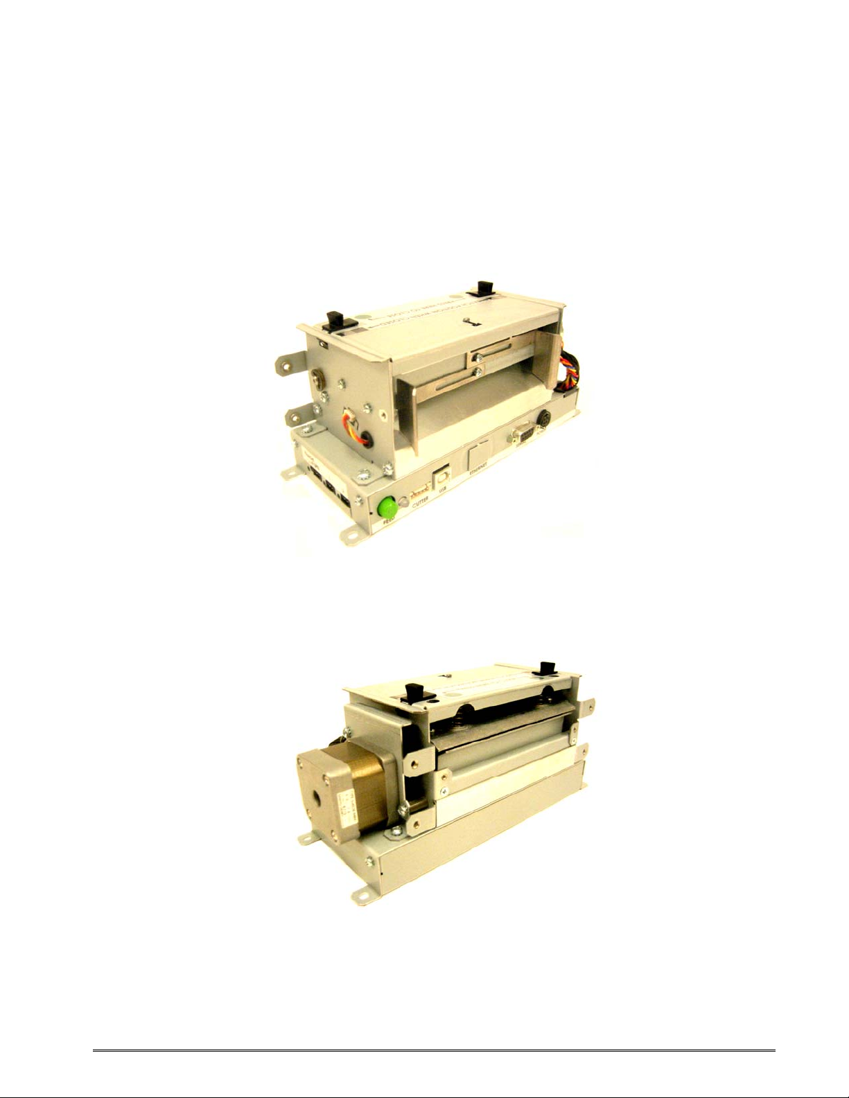
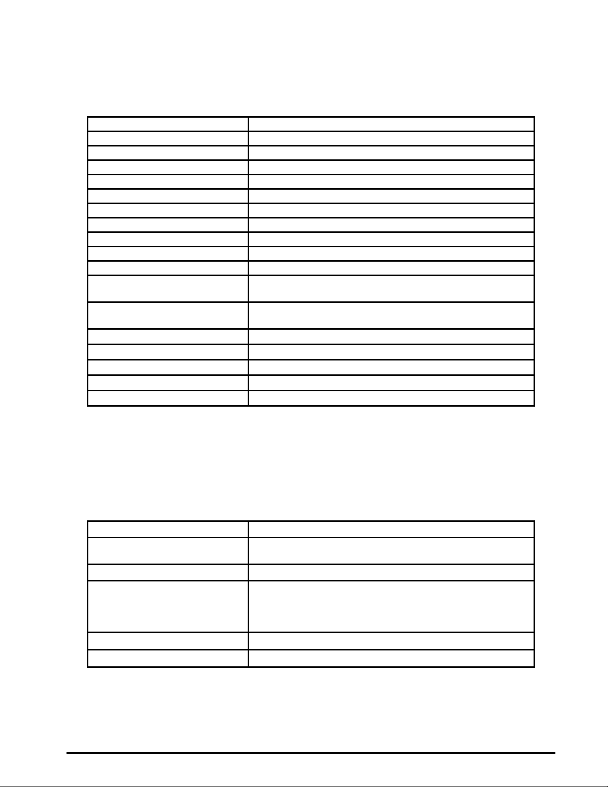
Introduction
The Model 324M and 424M printers are high performance Direct Thermal open frame
printers specifically designed for kiosk, OEM, and specialty applications. The only
difference between the two printers is the width of the print head: the 324M has a 3” wide
print head, and the 424M has a 4” wide print head. All other features are the same on both
printers.
Rear Side View
Front Side View
324M/424M Operator’s Manual – 880026-1000 vii
Page 12

viii 324M/424M Operator’s Manual – 880026-1000
Page 13
Chapter 1: Printer Specifications
1.1 General Specifications
Width* 8.53” (217 mm)
Height* 4.00” (102 mm)
Depth* 3.50” (88.9 mm)
Weight* 4.16 lbs. (1.9 kg)
Electrical +24 VDC
Current 3 Amps maximum
Temperature 40° F – 158° F (5° C – 70° C) Operating
Humidity 10% – 85%, non-condensing
SRAM Memory 512 K
Code Flash Memory 512 K
User Flash Memory 8 MB
Agency Approvals
Interface Communications
Flow Control XON, XOFF, and CTS
Baud Rate 110 to 115200
Parity Odd, Even, and None
Data Bits 7 or 8
Protocols TCP/IP
• NOTE: Listed specifications are based on a standard print mechanism and may vary
based on final configuration.
Table 1-1 General Specifications
Designed to meet CUL, CE, and complies with FCC
Class A
RS-232 (9 pin D-Sub connector (DCE)), USB (version
1.1 supported), and optional 10/100BASE-T Ethernet
1.2 Printing Specifications
Print Type Direct Thermal
Print Resolution
Maximum Print Speed 8”/sec. (203 mm/sec.)
Maximum Print Width
Maximum Print Length 50” (1,270 mm)
Minimum Print Length 0.25” (6 mm)
Table 1-2 Printing Specifications
324M/424M Operator’s Manual - 880026-1000 1-1
203 DPI (8 dots/mm = 0.0049” per dot)
300 DPI (12 dots/mm = 0.0032” per dot)
324M 203DPI = 3.152” (80.08 mm); 640 dots
324M 300DPI = 3.200” (81.28 mm); 960 dots
424M 203DPI = 4.098” (104.10 mm); 832 dots
424M 300DPI = 4.266” (108.37 mm); 1,280 dots
Page 14

Printer Specifications Chapter 1
1.3 Media Specifications
Media Types
Maximum Media Thickness .010” (.25 mm)*
Maximum Media Width
Continuous, die-cut, preprinted and tag stock either rolled
or fanfold
324M = 3.5” (89 mm)**
424M = 4.5” (115 mm)***
Table 1-3 Media Specifications
*NOTE: The printers may print on thicker media types depending on the pliability of the
material; however, this requires testing and evaluation. Contact your authorized Microcom
Corporation representative for additional information regarding testing and evaluation of
thicker or rigid media types.
**NOTE: The 324M printer’s media path has a maximum width of 3.5” while the actual
printable width is 3.15” for the 203 DPI and 3.189” for the 300 DPI print head.
***NOTE: The 424M printer’s media path has a maximum width of 4.5” while the actual
printable width is 4.095” for the 203 DPI and 4.252” for the 300 DPI print head.
The printers may be optimally configured with fixed media guides to assist in the installation
of media.
1-2 324M/424M Operator’s Manual - 880026-1000
Page 15

2.1 Fonts
• 7 (203 DPI) smooth bitmapped alpha-numeric fonts from 6pt to 14pt.
• TrueType® font capability using Microcom Corporation utility program.
• 19 (203 or 300 DPI depending on the print head resolution) downloadable
standard font set.
• All bitmapped fonts expandable in height and width.
• Reverse image printing.
• Rotated: 0 º, 90 º, 180 º, and 270 º.
2.2 Graphics
• Resident Lines feature.
• Storage of fonts, label formats and graphics in both volatile RAM and non-
volatile FLASH memory.
Chapter 2: Features and Options
• All BMP files may be converted using a Microcom utility program.
• Rotated: 0 º, 90 º, 180 º, and 270 º.
2.3 Bar codes
• One-dimensional
• Code 39
• Interleaved 2 of 5
• Code 128 (A, B, C and
• Code 93
• Codabar
• Modified Plessey
• UPC-A
• UPC-E
• EAN 8
• EAN 13
• UCC/EAN 128
• Postnet.
Auto)
• Two-dimensional
• RSS-14
Standard
Truncated
Stacked
Omnidirectional
Limited
Expanded
• PDF-417
• Maxicode.
• Rotated: 0 º, 90 º, 180 º, and
270 º.
• Expandable in height and
width.
324M/424M Operator’s Manual - 880026-1000 2-1
Page 16

Features and Options Chapter 2
2.4 Special Features
• 3 Serial Data inputs
• RS-232D, up to 115,200 baud
• USB 1.1
• Rotating head mechanism for easy print head cleaning
• Adjustable media guides for easy label centering or custom fixed guide
brackets
• Software controlled contrast adjustment
• Detects label gap, black line, and blow-hole using reflective and
transmissive sensors
• Field incrementing, decrementing, and serialization
• Downloadable fonts and graphics (with data compression)
• Internal statistical counters for inches and labels printed
• Remote printer interrogation
• Two types of mounting methods for kiosk installation flexibility
• On-site programmable flash memory updates
• Supports 203 dpi and 300 dpi print heads
• Four +24VDC control INPUTS
• Four +24VDC control OUTPUTS
• Automatic stock eject on paper-out
2.5 Options
• 3.425” (87mm) or 4.488” (114mm) Guillotine cutter, Full Cut Only, 170 g/m
• 3.425” (87mm) or 4.488” (114mm) Guillotine cutter, Full/Partial, 120g/m2
• 3.425” (87mm) or 4.488” (114mm) Rotary cutter, Full Cut Only, 200g/m2
• +24 VDC Universal 85W Desktop Power Supply for 70°C
• +24 VDC Universal 100W Desktop Power Supply
• +24 VDC Universal 150W Desktop Power Supply with Hi-Temp Fan
2
• Two reflective sensor inputs with indicator lights (Input 1 and Input 2)
• Label Present Detector (LPD) reflective sensor with indicator light and
adjustable range
• Printed Media Presenter (PMP)
• 10/100BASE-T Ethernet communications port
• Remote print button and unit indicator light
• Cleaning kit
2-2 324M/424M Operator’s Manual - 880026-1000
Page 17
Chapter 3: Getting Started
3.1 Unpacking and Inspection
The printer has been packaged in protective foam to help reduce the damage during
shipment.
Inspect the shipping container(s) for signs of damage. If damage is evident, contact the
shipping company immediately to file a damage claim.
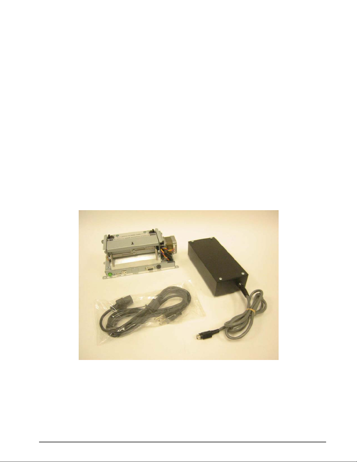
After the printer is removed from the container(s), verify that all the items on the packing list
are present and in good condition. The picture below (See Figure 3-1) shows a 424M
printer, optional power supply, and optional power cord. Your shipment may contain
different items.
The foam and shipping container(s) should be kept and used if the printer is to be shipped
at a later time. Additional shipping materials can be ordered by contacting the Microcom
Corporation Service Department.
Figure 3-1 Typical Printer Accessories
324M/424M Operator’s Manual - 880026-1000 3-1
Page 18
Getting Started Chapter 3
3.2 Connecting the Printer
The printer’s may be interfaced to PC’s, mini-computers, main frames, and special purpose
machines using the available communications ports described in the following sections.
3.2.1 Printer Power
Microcom Corporation offers three (3) different “Desktop” universal power supplies as
options. Any power supply that conforms to the standard supply specifications listed in
Table 3-1 below may be used. The printer requires a universal +24VDC power supply that
operates in the 100-240 VAC; 50-60 Hertz range; 4 Amps. The power supply should
operate in an “output foldback mode” during an overload situation rather than a shutdown
and restart attempt; sometimes referred to as a “Hiccup” mode. Contact your Microcom
Corporation representative for any questions regarding power adapter requirements and/or
specifications.
AC Input: 100-240 VAC, 50/60 HZ, 4A
DC Output: +24V @ 0.2 ~4.16A +/- 5%
Power Rating:
Overload Protection: Output Voltage Foldback Mode
Maximum Transient Load:
Printer Power Connector: Standard 4-pin power mini-DIN
Table 3-1 100 Watt Power Supply, w/o Fan 40°C
AC Input: 100-240 VAC, 50/60 HZ, 4A
DC Output: +24V @ 0.2 ~6.25A +/- 5%
Power Rating:
Overload Protection: Output Voltage Foldback Mode
Maximum Transient Load:
Printer Power Connector: Standard 4-pin power mini-DIN
Table 3-2 150 Watt Power Supply, with Fan 60°C
AC Input: 100-240 VAC, 50/60HZ, 4A
DC Output: +24V @ 0.2 ~4.16A +/- 5%
Power Rating:
Overload Protection: Output Voltage Foldback Mode
Maximum Transient Load:
Printer Power Connector: Standard 4-pin power mini-DIN
Table 3-3 85 Watt Power Supply, w/o Fan 70°C
100 Watts, no cooling, 40
12 cycles @ 2.1ms rep. rate;
35A, 650µs pulse
150 Watts, internal fan cooling, 60
12 cycles @ 2.1 ms rep. rate;
35A, 650 µs pulse
85 Watts, no cooling, 70
12 cycles @ 2.1ms rep. rate;
35A, 650µs pulse
°C
°C
°C
3-2 324M/424M Operator’s Manual - 880026-1000
Page 19
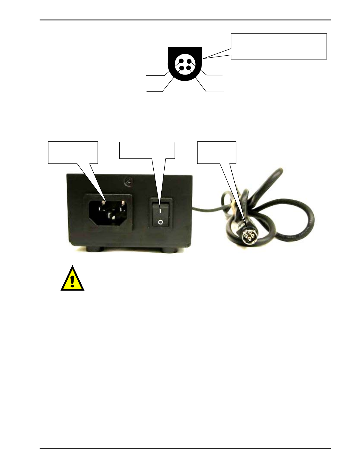
Chapter 3 Getting Started
View of Optional Desktop Powe
Supply
Output cable connector
r
GND
+
GND
+24V
Figure 3-2 Optional Desktop Power Supply Output
AC Input
(115-230VAC)
On/Off Switch
DC Output
(+24 VDC)
Note: Verify that the printer’s On/Off switch is switched “off” before
plugging in the power cord into the electrical outlet and the power
supply’s output cable into the printer.
Figure 3-3 Connecting the Power
3.2.2 RS232 Serial Communication Interface
The printer provides a 9-pin female D-Sub connector, on the rear panel, for RS-232D serial
communication. The printer is configured as DCE (Data Circuit-terminating Equipment) so a
NULL modem cable is not necessary. A serial data cable is required to use serial
communications, refer to
The factory settings, unless otherwise requested, are set at 115200 baud, 8 data bits, 1 stop
bit and no parity with both hardware and software handshaking enabled. The baud rate is
user selectable from 110 to 115,200 and uses software XON/XOFF flow control and/or
hardware CTS handshaking.
Table 3-4 below for correct cable configurations.
324M/424M Operator’s Manual - 880026-1000 3-3
Page 20
Getting Started Chapter 3
If XON/XOFF handshaking is used, the only signals that the printer requires are the RXD,
TXD, and GND signals. If the hardware handshaking is used, then the CTS and RTS signals
are required. The other signals are offered in the event that the host computer would
require them.
3.2.2.1 RS-232 Serial Cables
The printer uses a standard through serial cable, typically referred to as a modem cable,
which may be purchased through Microcom Corporation or a local computer supply
company. A NULL-modem cable is not required because the printer is configured as DCE.
For a 25-pin serial communication port – Use a 25-pin female to 9-pin male cable.
For a 9-pin serial communication port – Use a 9-pin female to 9-pin male cable.
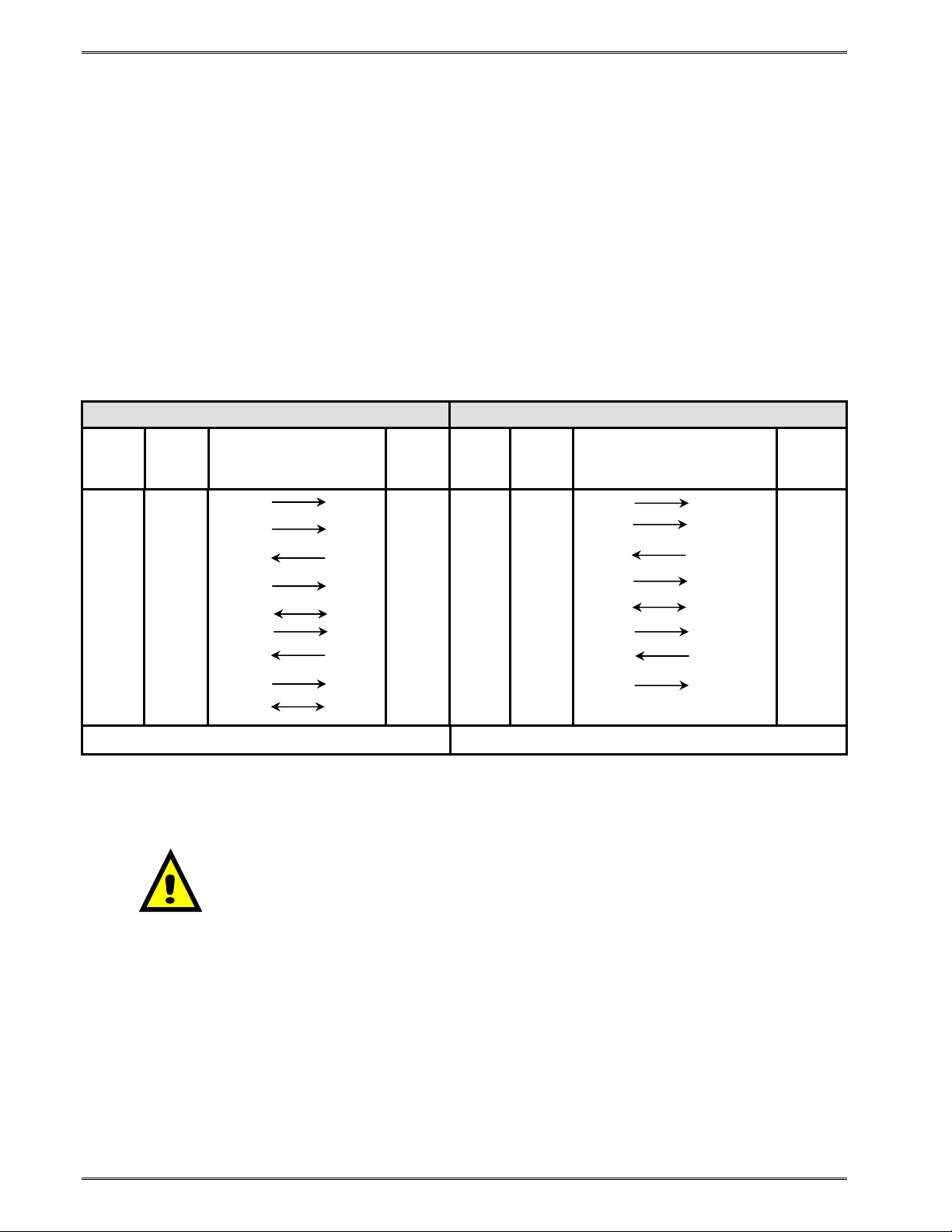
9 to 9 Pin Cable 9 to 25 Pin Cable
DE-9
State
XX 1 DCD
XX 2 TXD
XX 3 RXD
HI 4 DTR
LO 5 GND
HI 6 DSR
DC 7 RTS
XX 8 CTS
HI 9 +5V
Pin #
Signals /
Directions
PC
DE-9
Pin #
DCD 1 HI 1 DCD
RXD 2 XX 2 TXD
TXD 3 XX 3 RXD
DSR 4 HI 4 DTR
GND 5 LO 5 GND
DTR 6 HI 6 DSR
CTS 7 DC 7 RTS
RTS 8 XX 8 CTS
+5V 9 HI 9 +5V -
State
DE-9
Pin #
Signals /
Directions
DCD 8
RXD 3
TXD 2
DSR 20
GND 7
DTR 6
CTS 4
RTS 5
PC
DB-25
Pin #
DC = DO NOT CARE XX = INDETERMINATE
Table 3-4 RS-232 Cable Configurations
CAUTION: Connection of a serial port to a parallel port may
result in damage to the printer and/or computer.
3.2.3 USB Communication Interface
A standard USB 1.1 connector is provided on the rear panel of the printer. The USB port
operates as a virtual serial communications port and requires the installation of the
Microcom Corporation supplied USB driver for proper operation. The USB cable must be
connected to a host PC that is already powered on before the printer is turned on. The
^D108 command is used to select the USB port and requires a power cycle to take affect.
3-4 324M/424M Operator’s Manual - 880026-1000
Page 21

Chapter 3 Getting Started
3.2.4 Optional Ethernet Communication Interface
The Model 324M and 424M printers provide an optional 10/100BASE-T Ethernet connector
on the rear panel of the printer. The ^D108 command is used to select the Ethernet port at
power up.
3.2.5 Optional Cutter Interface
The printer is fitted with a connector on the rear panel for the optional cutter interface. Use
this connector when a cutter is to be installed on the printer. To prevent damage to the
printer and/or cutter, connect the cutter when the printer power is off. The cutter type is set
by the user using the ^D115 command and will be reported on the Statistics Label.
3.2.6 LPD Sensor Input
A Label Present Detector connector port is provided on the right side panel of the printer to
operate the optional LPD sensor. The LPD sensor detects when media is present on the
output side of the printer, and is used in conjunction with the tag/tear and peel-n-dispense
commands. A potentiometer is labeled as “RANGE” and is used to adjust the detection
range of the sensor. The maximum detection range may be adjusted from 0.20” to 0.85”
measured from the surface of the sensor to the reflecting surface of the media. A red LED
is provided (located left of the port) as a visual reference indicating media detection. If
using either the ^D97 tag/tear or ^D98 peel-n-dispense commands, the printer will also
issue the >TAKE LABEL< response when an enquiry request is issued.
3.2.7 Sensor Inputs 1 and 2
The printer provides two (2) General Purpose reflective sensor input ports on the right side
panel of the printer. These optional sensors are typically used to sense the presence or
absence of label media or a full catch tray.
These inputs, labeled “INPUT 1” and “INPUT 2”, have a fixed detection range of 0.85”
measured from the surface of the sensor to the reflecting surface or media.
3.2.7.1 Sensor INPUT 1
Input 1 provides a visual reference (amber LED) when the sensor is “tripped.” The printer
issues an >INPUT 1< when an enquiry response (^E) is requested. The active state
(normal or inverted) of the Input 1 is determined by the software switch bank 3, location 2
(^D23 Command).
3.2.7.2 Sensor Input 2
Input 2 provides a visual reference (green LED) when the sensor is “tripped.” The printer
issues an >INPUT 2< when an enquiry response (^E) is requested. The active state
(normal or inverted) of the Input 2 is determined by the software switch bank 3, location 4
(^D23 Command).
324M/424M Operator’s Manual - 880026-1000 3-5
Page 22
Getting Started Chapter 3
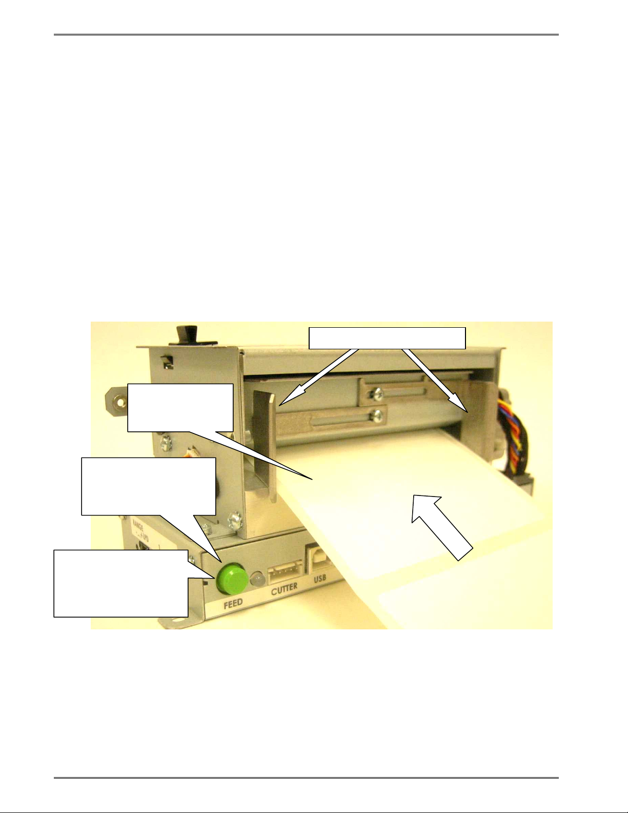
3.3 Loading Media
The easy- to-release print head makes loading media into the Model 324M/424M printer an
easy process. Follow the instructions below to properly load the media.
1. Feed the media into the paper path, located on the back of the printer, until you feel
resistance.
2. Push and hold the Print Button to feed the media through the printer.
3. Once the media exits the front of the printer, release the Print Button.
The printer is also equipped with an AutoLoad feature. This feature allows the printer to
automatically sense new media as it is inserted into the printer, and automatically feed the
media to provide proper registration of the first label/tag to either the leading edge or a
registration mark. For more details on this feature, please refer to Chapter 5, AutoLoad
Commands.
Step 2.
… then press and hold
Print Button to advance
label stock.
Step 3.
Print test labels until print
is properly registering
with label stock by
tapping Print Button.
Step 1.
Insert label stock
here until it stops…
Figure 3-4 Loading Media
Adjustable Paper Guides
3-6 324M/424M Operator’s Manual - 880026-1000
Page 23
Chapter 3 Getting Started
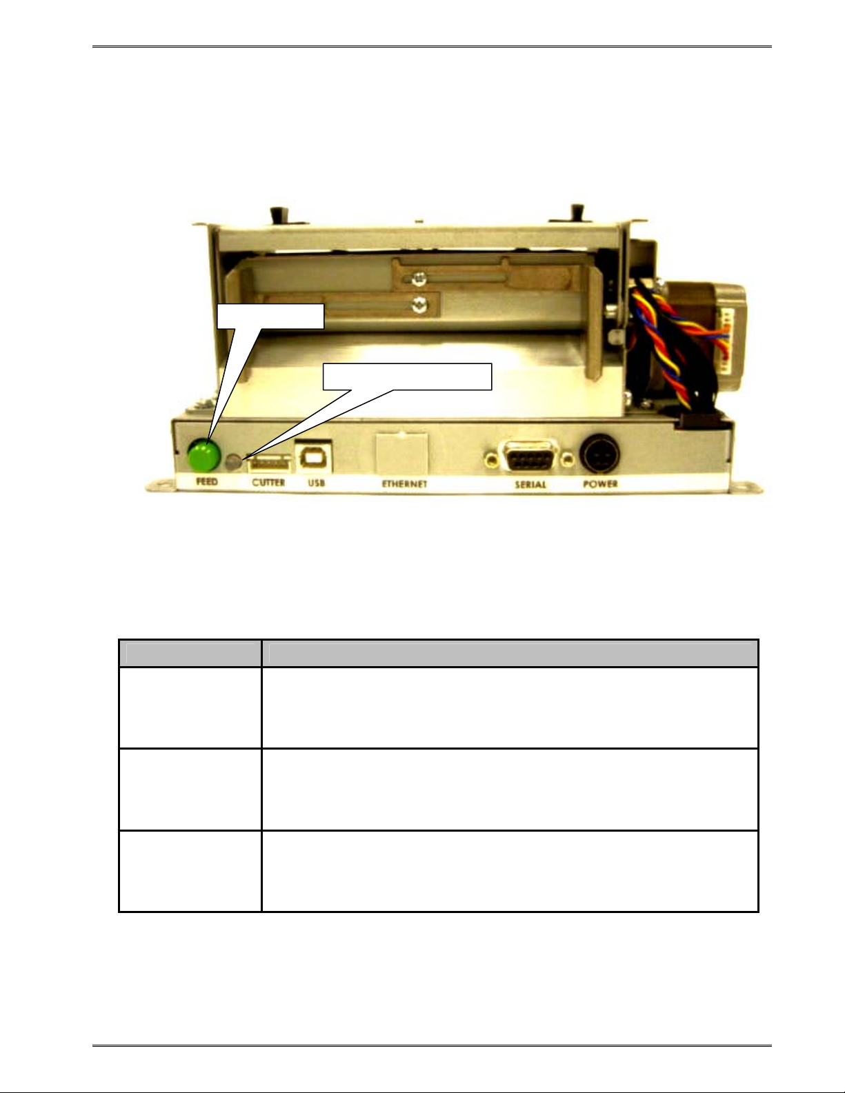
3.4 Print Button and Status Indicator Light
The Print Button and the Status Indicator Light are used to identify and perform many
functions. This section provides a description to familiarize you with the basic function of
the Print Button and the Status Indicator Light.
Print Button
Status Indicator Light
Figure 3-5 Print Button and Status Indicator Light
3.4.1 Print Button
Operation Description
Press the Print Button while the printer is IDLE or PAUSED to
Printing a label
Pause printing
Feeding labels
(Line feed)
reprint the last label.
A power up label will print after a power ON cycle when the Print
Button is pressed.
Press the Print Button briefly while the printer is printing to enter
the PAUSED mode.
Press the Print Button again to continue printing.
Press & hold the Print Button while the printer is IDLE to advance
label media. The printer will continue advancing label media until
the Print Button is released.
Table 3-5 Print Button Description
324M/424M Operator’s Manual - 880026-1000 3-7
Page 24
Getting Started Chapter 3
3.4.2 Status Indicator Light
Light Color Description
Solid Green
Solid Red
Solid Amber
Flashing Red
Indicates that the power is on and the printer is in a ready state.
Indicates an error has occurred. The printer will remain in this
state until the condition is removed. If an unexplained error
persists, contact your Service Representative.
The printer is in the Tag/Tear or Peel-and-Dispense mode and is
waiting for the label/tag to be taken.
OR
Indicates that the printer is in the Boot Loader mode (MCB) and is
not running the printer application program.
A cutter error has occurred.
OR
A memory download operation was not successful.
OR
Power Spike or low voltage on the AC line. (The printer will
remain in this mode until the condition is removed and the printer
power is cycled.)
Flashing Amber Printer is PAUSED,
Table 3-6 Status Indicator Light Description
3.5 Printer Modes
The printer has four primary modes of operation. The different types of modes have an
impact on how the Print Button and the Status Indicator Light operate. This section is
intended to provide the user with an explanation of these different modes.
3.5.1 Idle Mode: GREEN
The printer is in the IDLE Mode when it is not printing and/or has no pending activity. The
indicator light is GREEN, which indicates that the printer is ready to receive label formats
and/or commands.
In IDLE Mode the Print Button has several different functions:
1. Pressing the button quickly will reprint the last label
2. If the printer was just turned ON and no formats were sent to the printer,
pressing quickly will print the power-up label,
3. Holding the button depressed: Form Feed labels until the button is released.
3-8 324M/424M Operator’s Manual - 880026-1000
Page 25

Chapter 3 Getting Started
3.5.2 Halted Mode: RED
The printer is in the HALTED Mode when it has stopped due to an error condition. The
Status Indicator Light will be solid red in color when the printer has entered the HALTED
Mode. The printer will remain in this mode until the error has been corrected and cleared.
Once the error has been cleared, the printer will attempt to execute the previous format
and/or commands.
3.5.2.1 Steps to clear the >STOCK OUT< error
a) Load new label media.
b) Press the Print Button quickly to start printing.
c) Press the Print Button until label is properly registering on media.
d) Press the Print Button again during printing to resume batch printing.
3.5.2.2 Steps to clear the >STOCK OUT< error with “E-Z Out function”
If Soft Switch #5, Bit #1 is set to “1”, then a single quick press of the Print
Button will clear the >STOCK OUT< error once the printer has more label
media loaded.
3.5.2.3 Automatic Stock Eject on >STOCK OUT<
The printer performs an Automatic Stock Eject operation whenever it runs out
of label media. As soon as the >STOCK OUT< condition is detected, the
printer feeds the label media forward to clear the drive roller.
The feed distance is just enough to eject the last of the label media past the
drive roller and then stop. This happens automatically…the user doesn’t have
to hit the Print Button.
3.5.3 Paused Mode: Solid or Flashing AMBER
There are several ways that the operator can control the output of the printer. The printer
will display either solid or flashing AMBER depending upon the mode of operation. Also,
the printer will display a solid AMBER during a FLASH operation.
Solid AMBER A printed tag/label is waiting to be taken by the operator when the
printer is in a Tag/Tear (^D97) or Peel-and-Dispense (^D98) mode.
The printer is in the FLASH mode.
Flashing AMBER Pressing the Print Button during tag/label printing will pause printing. It
will resume printing by pressing the Print Button again.
3.5.4 Diagnostic Mode
The Diagnostic Mode temporarily powers up the printer using factory default parameters.
Also, the printer’s current user configuration parameters and statistical information are
printed out on a Status Label. This provides useful information to help diagnose and
troubleshoot problems. The printer will use the factory default parameters until the printer
has been reset using a soft reset or by cycling power. The printer will then return to the
configuration shown on the Status Label.
324M/424M Operator’s Manual - 880026-1000 3-9
Page 26
Getting Started Chapter 3
3.5.4.1 Entering Diagnostic Mode
To enter the Diagnostic Mode, press and hold the Print Button “IN” while turning the printer
“ON.” Release the Print Button after printer begins to print the Status Label. The printer will
enter the DIAGNOSTICS Mode, and print the Statistics label and a print test pattern.
In the DIAGNOSTICS Mode, the printer is forced to use the RS-232 port at 115,200 baud.
The normal Soft Switch settings are ignored, and factory default settings are loaded into the
printer. These default settings will remain in effect until the printer power is cycled or a Soft
RESET command is issued (^D32). These are the only 2 ways to get out of the
DIAGNOSTICS mode.
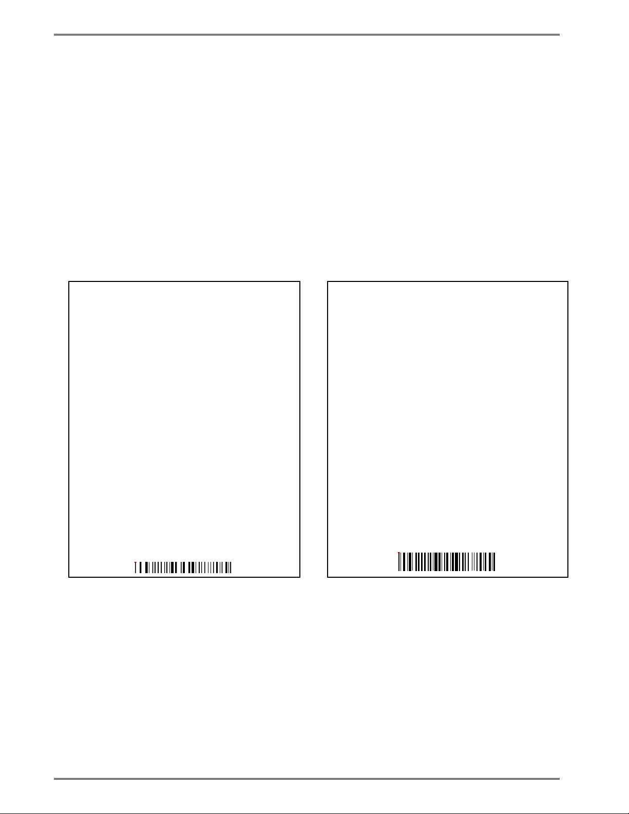
3.5.4.2 Statistics Label
The Statistics Label may be printed either by entering the DIAGNOSTICS Mode or sending
the Printing Statistics Command.
PRINTER SERIAL #: 00516645051
PRINTED LABELS: 303
PRINTED INCHES: 1533
TOTAL INCHES: 1571
POWER ON HOURS: 32.8
CUTTER TYPE: Guillotine
CUTTER ENABLED?: YES
CUTTER COUNTS: 1789
KIOSK CUT MODE: Disabled
KIOSK DISTANCE: 0
SWITCH BANK 1: 10001010
SWITCH BANK 2: 01010001
SWITCH BANK 3: 00000000
SWITCH BANK 4: 00000000
SWITCH BANK 5: 00000000
SWITCH BANK 6: 00000001
CURRENT COMM PORT: Autoselect USB/RS232
RS232 PARAMETERS: 115200-N-8-1
PRINT HEAD SIZE: 1280
PRINT HEAD DPI: 300
% CONTRAST: 100
D91 GAP VALUE: 30
TOF DISTANCE: 179
STOCK OUT VALUE: 100
PRINTER CODE REV: 02.12.050719A
BOOTLOADER CODE REV: 02.12.050719A
CODE ASSY PN. 071001-0212
PRINTER SERIAL #: 00516645051
PRINTED LABELS: 303
PRINTED INCHES: 1533
TOTAL INCHES: 1571
POWER ON HOURS: 32.8
CUTTER TYPE: None
KIOSK CUT MODE: Disabled
KIOSK DISTANCE: 0
SWITCH BANK 1: 10001010
SWITCH BANK 2: 01010001
SWITCH BANK 3: 00000000
SWITCH BANK 4: 00000000
SWITCH BANK 5: 00000000
SWITCH BANK 6: 01110010
CURRENT COMM PORT: Autoselect USB/RS232
RS232 PARAMETERS: 115200-N-8-1
PRINT HEAD SIZE: 1280
PRINT HEAD DPI: 300
% CONTRAST: 100
D91 GAP VALUE: 30
TOF DISTANCE: 160
STOCK OUT VALUE: 100
PRINTER CODE REV: 02.12.050719A
BOOTLOADER CODE REV: 02.12.050719A
CODE ASSY PN. 071001-0212
Figure 3-6 Status Label (Examples)
3-10 324M/424M Operator’s Manual - 880026-1000
Page 27
Chapter 3 Getting Started
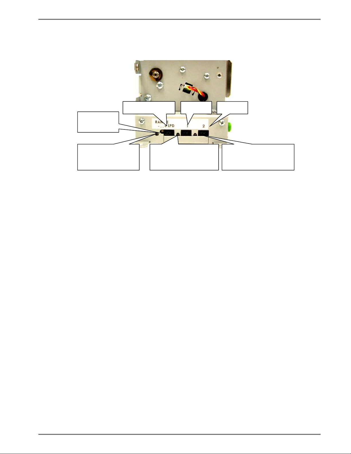
3.6 Sensor Inputs
LPD Range
Adjustment
LPD Sensor LED
(Flashes red when
label is present)
LPD Sensor Port Input 1
Input 1 Sensor LED
(Flashes amber when
label is present)
Input 2
Figure 3-7 Sensor Input Ports
Input 2 Sensor LED
(Flashes green when
label is present)
1) LPD (Label Present Detector). Used to detect when a printed label is present. A
potentiometer is provided to adjust the distance over which the LPD sensor will
detect reflections. The maximum range may be adjusted over a distance of 0.20”
Ö 0.85”. Distances are measured from the surface of the sensor to the reflecting
surface. This pot may be used to decrease sensor range to avoid false reflections
from stationary objects such as a cutter.
2) INPUT 1 This general purpose input is a reflective sensor typically used with
custom applications to sense when stock is running low. This enables the
operator to replenish stock before a >Stock Out< condition occurs. The active
state of the signal is programmable thru Soft switch #3, bit #2. An active state will
return an >INPUT 1< response when queried. An “amber” LED beside the port is
lit when reflection is detected. The maximum pick-up range is not adjustable and
is set to sense a reflection up to 0.80” from the sensor’s surface.
3) INPUT 2 This general purpose input is a reflective sensor typically used with
custom applications to sense when stock is running low. This enables the
operator to replenish stock before a >Stock Out< condition occurs. The active
state of the signal is programmable thru Soft switch #3, bit #4. An active state will
return an >INPUT 2< response when queried. A “green” LED beside the port is lit
when reflection is detected. The maximum pick-up range is not adjustable and is
set to sense a reflection up to 0.80” from the sensor’s surface.
Note: Sensor range will vary depending upon the reflective quality of the printed media
stock.
324M/424M Operator’s Manual - 880026-1000 3-11
Page 28

Getting Started Chapter 3
3-12 324M/424M Operator’s Manual - 880026-1000
Page 29

Chapter 4: Designing Labels Using LDS
Label Design Software (LDS) refers to the control language resident in the printer used to
create labels. All bitmapped fonts, character sets and bar codes are resident in the printer.
Additional fonts and graphic images may be sent from a host and stored in the printer’s
memory.
A label format is produced by a series of 5 steps:
1. Control commands to define printer operation.
2. A format header to define the label height, width, print speed, etc…
3. Field data that defines the placement of text, bar codes, graphics or lines.
4. Actual text data to place in the Field data strings.
5. Control commands to initiate printing.
4.1 Control Characters
Throughout this manual there are references to control characters. In order to print them in
this manual, they have been written using standard characters and icons. Escape
characters are represented by <ESC> and a carriage return is represented by <CR>. It is
important to note that all printer functions, unless otherwise noted, must be followed or
terminated with a carriage return (<CR> or HEX OD). The printer ignores the <LF> (Line
feed) or HEX oA character so it si easier to read and troubleshoot files if the <LF> character
is sent after the <CR> character.
Note: Control codes are ignored when the printer is configured for binary compression
mode (^D23, bit 7).
4.2 LDS Design Exercises
There are many different machines capable of sending information to the printer including
main frames, mini-computers, special purpose computers and PC’s. For the purpose of
simplicity, the design exercises contained in this manual will use one of the easiest methods
by using an IBM compatible PC and a VT-100 terminal emulation software program. This
method of connection will allow two-way, serial communication with the printer.
Items required:
- A computer with at least one unused serial communication port (COM1, COM2…).
- A serial interface cable.
- A VT-100 terminal emulation program such as HyperTerminal™.
- A text editor that does not add formatting characters such as Microsoft® Notepad.
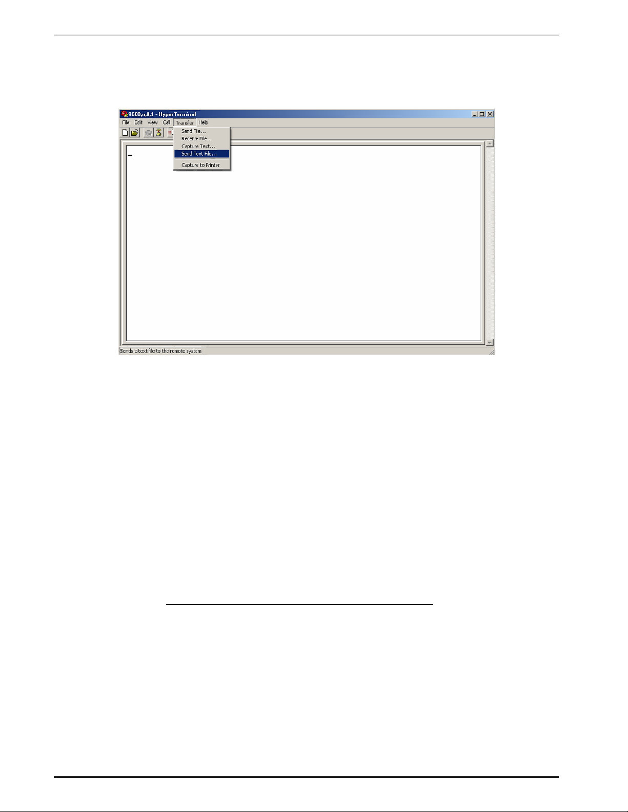
4.2.1 PC Connection (Serial)
The printer is shipped with serial communication parameters set to 115200 bits per second,
no parity, 8 data bits, and 1 stop bit (115200-N-8-1). This means that for proper
communication, the PC’s communication port must be set to these parameters. If a terminal
program is not available, it is possible to send files to the printer using the DOS COPY (for
example: C:\>COPY FILENAME COM1) command. When using DOS, set the
communications port up using the DOS MODE (for example: C:\>MODE
324M/424M Operator’s Manual - 880026-1000 4-1
Page 30
Designing Labels Using LDS Chapter 4
COM1:115200,n,8,1,p) before copying the files to the port. Create a text file, enter “^D3”
<CR> (carriage return) and save it as “D3.txt”. Send the file to the printer by either using the
DOS COPY (C:\>copy d3.txt com1) command or by using a terminal program.
Figure 4-1 HyperTerminal™ Window Example
4.2.2 Format Creation
Special Control code functions (see Chapter 5, Special Control Codes) and/or label formats
may be entered directly through the keyboard but this is not the most efficient method if
entering a large amount of data or numerous commands. Large formats and/or numerous
commands should be entered in an ASCII text editor and then uploaded to the printer.
Microsoft® Notepad has been used for the creation of label designs in this manual because
it is simple to use and does not add formatting characters.
The LDS programming language uses thermal dots as the unit of measure. All commands
and parameters, unless noted otherwise, should be entered using dots. The 324M and
424M printers may be fitted with either a standard density 203dpi head, or a higher density
300dpi print head.
These are the conversion values for each print head:
Print head Dots/mm Dots/inch Inch/Dot
203 8 203 0.0049
300 12 300 0.0033
EXAMPLE: To enter the width of a label that is 2” wide when using a 203dpi head, the
value entered would be 406 (2” x 203 dots/in. = 406).
The printer can accept either the one-character control code (“Ctrl + E” (HEX05)) or the twocharacter caret (^) plus alpha character (“^E”). In other words, for a PC keyboard, the same
command can be generated either by holding down the “Ctrl” key and pressing the alpha
character or by entering the two characters; the “^” (the character generated when you
4-2 324M/424M Operator’s Manual - 880026-1000
Page 31

Chapter 4 Designing Labels with LDS
press the “Shift” key and the “6”) plus the alpha character. See Chapter 5 for additional
information regarding control codes and printer commands.
There are some special features offered by the printer that assist in label design. For
example, the auto-size command (^A2^D39 <CR>) provides most of the header format
information needed to define the different properties of the media being used. The current
state of the printer is accessed through the enquiry command (^D5 <CR>, Ctrl E, or 5 NULL
characters + 01(HEX 00 00 00 00 00 01) if binary compression has been enabled). The
statistical information of the printer is made available through the use of the ^A0^D29 <CR>
or more simply ^D29 <CR> command.
The following sections of this chapter are intended to provide the user an overview of the
LDS language. The overview will include information regarding the label format, header
definition, and list the different types of field information available. The combination of these
sections and Chapter 5 should provide the user with the information required for easy format
creation and printing. Once some understanding of these basic concepts has been
achieved, use the Quick Reference Guide in Appendix C for expedient label design.
4.3 Label Design: An Overview
A label format consists of a header record and field records, followed by the text data to be
printed. The records describe how the label is to be printed. The header contains
information about the label itself such as label height, width, print speed, etc. The field
records refer to the data section and contain information about positioning coordinates, and
the type of character generation such as text, graphics, bar codes, etc. The number of
fields is limited only by the amount of free memory available.
Below is a sample label format created for the Model 424M with a 300 DPI print head. We
will refer to this format as we break down the steps and components to produce the format.
Refer to Error! Reference source not found. for a printed representation.
^D57 <CR> A label format is coming.
5,1280,900,19,38,7,0,1,405,0,0 <CR> Header Information.
1,640,650,8,1,5,0,4,2,2,,,,,0 <CR> Field #1 format information.
2,640,591,11,1,5,0,4,2,2,,,,,0 <CR> Field #2 format information.
3,640,443,26,1,5,0,4 <CR> Field #3 format information.
4,640,296,6,1,5,0,4 <CR> Field #4 format information.
4,640,148,6,16,3,,4,3,75 <CR> Field #4 format information.
^D56 <CR> Signals the end of the label field definition .
^D2 <CR> Text data is coming.
Microcom <CR> Text data string #1.
Corporation <CR> Text data string #2.
Thermal Printing Solutions <CR> Text data string #3.
012345 <CR> Text data string #4.
^D3 <CR> Print label.
The command ^D57<CR> on the first line informs the printer that a format is coming and
causes the printer to enter the format entry mode.
324M/424M Operator’s Manual - 880026-1000 4-3
Page 32

Designing Labels Using LDS Chapter 4
The next line is the header information that sets the label size and other pertinent
information.
The next five lines are layout and configuration for each data field in the format.
The command ^D56<CR> selects the user’s layout or more simply the end of the formatting
information.
The command ^D2<CR> instructs the printer to start accepting data for each of the defined
field’s strings that are entered into the previous format received (between the ^D57 and
^D56 commands). Field #1 defines the placement and configuration for Text Data String
#1; Field #2 defines the placement and configuration for Text Data String #2, etc… The
label is printed from the bottom left corner to the top of the label.
The next three lines are the text data for the associated field format lines.
Text Data String #4 is being accessed twice. The format places the Text “012345” on the
label and then is accessed again placing a Code39 symbol representing “012345” on the
label.
The command ^D3<CR> instructs the printer to print.
Thermal Printing Solutions
Figure 4-2 3x3 Sample Label
Microcom
Corporation
012345
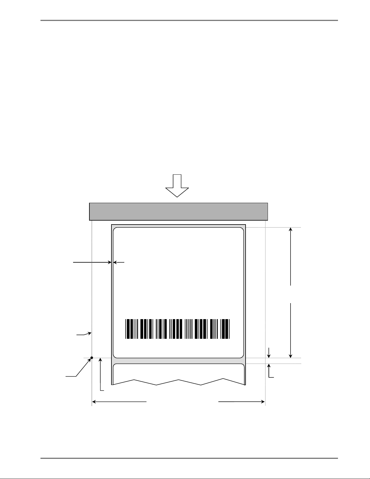
4.4 Label Header
The label header consists of eleven parameters that control the media layout as well as
printer configuration. A comma (,) delimiter is used to separate the parameters and a
carriage return is required to terminate the header.
The values for header elements requiring measurements are expressed as thermal dots or
pixels. Dot or pixel size varies depending upon the print resolution of the print head. Two
print resolutions are currently available for the 324M and 424M printers (203 DPI and 300
4-4 324M/424M Operator’s Manual - 880026-1000
Page 33
Chapter 4 Designing Labels with LDS
DPI). The dot size of a 203 dots per inch head (8 dots/mm) is 0.0049”. The dot size of a
300 dots per inch head (12 dots/mm) is 0.0032”. The dot size is the same in both the
horizontal and vertical direction. For example, a 4” X 6” label printed with a 203 DPI print
head would be 812 (4 X 203) dots in the horizontal or “X” direction, and 1218 (6 X 203) dots
in the “Y” direction.
While the maximum number of dots in the horizontal or “X” direction is limited by print head
size, it is virtually unlimited in the vertical or “Y” direction. Vertical dot rows are “stepped” by
the drive roller motor.
This is a list of the header element mnemonics for the sample label in Error! Reference
source not found.:
HFM, LSX, LSY, WEB, GAP, DPS, LCB, AGD, SPG, OFX, OFY
5 1280 900 19 38 7 0 1 405 0 0
Feed Direction
4” PRINT HEAD
Web Value
.0625” or
19 Dots
Thermal Printing Solutions
Microcom
Corporation
012345
LSY
3.0” or 900 Dots
X beginning
This is the
origin; 1,1
Y beginning
4.266” or 1280 Dots
(Total Print Head Dots)
LSX
Gap Value
.125” or 38 Dots
Figure 4-3 Header Elements
324M/424M Operator’s Manual - 880026-1000 4-5
Page 34
Designing Labels Using LDS Chapter 4
4.4.1 HFM (Number of Fields in Layout)
HFM, LSX, LSY, WEB, GAP, DPS, LCB, AGD, SPG, OFX, OFY
This parameter is used to specify the number of fields in the layout. If more format fields are
defined than specified in the HFM parameter, they will be ignored and will not print. The
HFM was set to a value of 5 in the format used to create the sample in Error! Reference
source not found.. This means that a total of five format fields are to be generated. If the
HFM were changed to 4, only the first four format fields would be generated.
4.4.2 LSX (Print Head Size X)
HFM, LSX, LSY, WEB, GAP, DPS, LCB, AGD, SPG, OFX, OFY
This parameter is used to specify the width of the print head using dots as the unit of
measure. The maximum width of the LSX parameter is determined by the width of the print
head. LDS has been specifically designed to accommodate a variety of print head widths.
These are the LSX values that should be used for proper print registration with various print
heads:
Print Width Dots/Inch # of Dots (LSX Value)
2.207” (56.05 mm) 203 448
2.133” (54.186 mm) 300 640
3.153” (80.08 mm) 203 640
3.200” (81.28 mm) 300 960
4.095” (104.00 mm) 203 832
4.110” (108.416 mm) 300 1280
Table 4-1 Valid LSX Values
4.4.3 LSY (Label Size Y)
HFM, LSX, LSY, WEB, GAP, DPS, LCB, AGD, SPG, OFX, OFY
This parameter is used to specify the height of the label using dots as the unit of measure.
The maximum height is virtually unlimited and is dependant only with available printer
memory. The label sample (Error! Reference source not found.) LSY measures 3” or 900
dots.
4.4.4 WEB (Web Size)
HFM, LSX, LSY, WEB, GAP, DPS, LCB, AGD, SPG, OFX, OFY
The WEB parameter is the width, measured in dots, of the webbing or backing material that
is found on the left side of a die-cut label. This parameter is used to introduce an offset to
accommodate the backing of die-cut media. The label sample (Error! Reference source
not found.) WEB measures .0625” or 19 dots.
4.4.5 GAP (GAP Size)
HFM, LSX, LSY, WEB, GAP, DPS, LCB, AGD, SPG, OFX, OFY
4-6 324M/424M Operator’s Manual - 880026-1000
Page 35
Chapter 4 Designing Labels with LDS
This parameter is the height, measured in dots, of the registration mark used to identify the
beginning of a label. The label sample (Error! Reference source not found.) GAP
measures 0.123” or 38 dots.
4.4.6 DPS (Print Speed)
HFM, LSX, LSY, WEB, GAP, DPS, LCB, AGD, SPG, OFX, OFY
The DPS parameter is used to set the printing speed for the printer. Refer to Table 4-2 for
the list of print speeds, DPS values, and corresponding inches per second values. To print
at greater speeds, change the DPS value to a lower setting as shown on Table 4-2.
Generally, better print quality is achieved by printing at lower speeds, however this is also
dependent on the media and contrast settings as well.
Labels per minute can be calculated by the equation below:
IPS x 60 seconds
Labels per Minute =
Label Height
PRINT SPEED
DPS VALUE
00 203.2 8.0 480
01 190.5 7.5 450
02 177.8 7.0 420
03 165.1 6.5 390
04 152.4 6.0 360
05 139.7 5.5 330
06 127.0 5.0 300
07 114.3 4.5 270
08 101.6 4.0 240
09 88.9 3.5 210
10 76.2 3.0 180
11 63.5 2.5 150
12 50.8 2.0 120
MM PER INCHES PER INCHES PER
SECOND SECOND MINUTE
13 38.1 1.5 90
Table 4-2 DPS Values
4.4.7 LCB (Label Control Byte)
HFM, LSX, LSY, WEB, GAP, DPS, LCB, AGD, SPG, OFX, OFY
324M/424M Operator’s Manual - 880026-1000 4-7
Page 36

Designing Labels Using LDS Chapter 4
This parameter selects the method the printer uses for detecting registration marks on the
different media types. The Model 324M and 424M printers have both upper (transmissive)
and lower (reflective) gap detectors as standard equipment. The following sections discuss
the LCB settings for the different media types.
4.4.7.1 Die-Cut and Blow-Hole Media (setting = 0)
A selection of “0” in the LCB parameter instructs the printer to detect the leading edge of a
die-cut label or a “blow-hole” to identify the start of the next label. In this method light from
the lower sensor passes through the stock to the detector in the upper sensor. This is
referred to as “transmissive” sensing. The label sample (Error! Reference source not
found.) is die-cut, therefore, the LCB is set to “0”.
4.4.7.2 Continuous Media (setting = 2)
If the LCB parameter is set to a value of “2”, the printer will not search for a registration
mark. The gap detectors are only used for stock out conditions when set for continuous
media types. The printer will print all fields that contain data and then advance the media by
the amount specified in the SPG parameter of the header when the default AGD of “1” is
entered in the header. This means that fields that are left blank or text data for the
associating format fields that are left empty will not print.
For example: Imagine a receipt format that contains 100 lines. If data is provided for the
first 50 lines, the printer will not advance for the remaining 50 lines that have been left blank.
The printer would stop immediately after printing the 50th line and then advance the media
by the amount specified in the SPG header parameter.
When the AGD header parameter is set to “0”, the printer will advance the same amount of
media even when text data fields are left blank. In this case, the advance distance is
determined by adding the SPG parameter and LSY parameter values.
For example: Imagine the same format as mentioned above that has an LSY value of 900
(3” x 300 = 900), an SPG value of 385, and an AGD value of “0” that contains 100 format
lines. If text data is provided for the first 50 lines and the remaining 50 lines are left empty,
then the printer will print the first 50 lines, advance the next 50 lines, advance the remaining
LSY value, and then finally advance the SPG or 385 dots. Regardless of the format fields, if
the LSY is set to 900 and the SPG is set to 385 the printer will advance a total of 1285 dots
(900+385=1285).
4.4.7.3 Black Line Media (Reflective) (setting = 3)
The Reflective Black Line method is used when media using a black line for a registration
mark and reflective detection is desired; a “3” should be entered in the LCB parameter. This
setting will detect the leading edge of the black line by using the lower sensor only. The
light from the emitter in the lower sensor is reflected down to the detector in the lower
sensor. This method is the preferred method for detecting media containing a black line
and should be used whenever possible.
Note: The detector in the upper sensor is still used to detect a “paper out” condition.
4.4.8 AGD (Activate Gap Detector)
HFM, LSX, LSY, WEB, GAP, DPS, LCB, AGD, SPG, OFX, OFY
4-8 324M/424M Operator’s Manual - 880026-1000
Page 37

Chapter 4 Designing Labels with LDS
This parameter selects the number of step (dot rows) that the printer should skip before gap
sensing is activated. This value is usually set to “1”. It is a good idea to set it to a value to
ignore areas of pre-printed or perforated stock that might cause incorrect gap detection.
4.4.9 SPG (Steps Past Gap)
HFM, LSX, LSY, WEB, GAP, DPS, LCB, AGD, SPG, OFX, OFY
This parameter is used to specify the number of steps (thermal dots) to advance the media
after a registration mark has been detected. This parameter is required to properly register
print on each label. The table below lists proper SPG settings for particular printer
configurations when the LSY is greater than the parameter value.
Model/Print Head DPI D2G Value
324M/424M – 203 DPI 284
324M/424M – 300 DPI 438
Table 4-3 Dot to Gap Parameters
For media that has a LSY value less than the parameter value in table 4-3, the SPG will
need to be calculated. SPG can be calculated using this formula:
SPG = (D2G + LSY - DRM) mod (LSY + SBL)
NOTE: All values are in pixels or dots.
D2G = This is a physical distance from the registration sensors to the print head's dot row,
and is a specific value for each model.
LSY = This is the actual height of the media in pixels or dots.
DRM = The Distance to Registration Mark is the distance from the leading edge of the
printable area to the beginning of the registration mark.
SBL = The Space Between Labels is the non-printable distance between the media,
typically found on die-cut labels. If the media contains space between the actual
printable portions of the media being used, this would be the SBL parameter.
Please note that this does not reflect a blowhole or black line height, as these
registration marks are typically positioned within the printable area. When die-cut
media is used, this value is also used in the GAP header parameter.
Calculation Examples:
Die-cut Media:
A 424M 203 DPI printer being used with 3" x 1" media containing a .125" die-cut gap. The
SPG would be calculated as follows:
SPG = (D2G + LSY - DRM) mod (LSY + SBL)
324M/424M Operator’s Manual - 880026-1000 4-9
Page 38

Designing Labels Using LDS Chapter 4
SPG = (284 + 203 - 203) mod (203 + 25)
SPG = 284 mod 228
SPG = 56
D2G (468) = The Dot to Gap distance for a 203 DPI 424M printer (Table 4-3).
LSY (203) = The height of the printable area; 1" x 203 DPI = 203 dots.
SBL (25) = The Space Between Labels, or die-cut GAP in this case;
.125" x 203 DPI = 25 dots.
DRM (203) = The Distance to Registration Mark is from the leading edge of
the printable area to the next registration mark;
1" x 203 DPI = 203 dots.
The SPG can be fine adjusted by temporarily adding a line at dot row #1 using Line Draw
and adjusting the SPG number up and down to get desirable registration.
4.4.10 OFX (Offset X Direction)
HFM, LSX, LSY, WEB, GAP, DPS, LCB, AGD, SPG, OFX, OFY
This parameter is used to move or offset all format fields in the X direction without altering
the format fields coordinates themselves.
4.4.11 OFY (Offset Y Direction)
HFM, LSX, LSY, WEB, GAP, DPS, LCB, AGD, SPG, OFX, OFY
This parameter is used to move or offset all format fields in the Y direction without altering
the format fields coordinates themselves.
4.5 Sample Header
This is the header for the format used to generate the printed sample in Error! Reference
source not found. followed by a summary of the header values.
5,1280, 900, 19, 38, 7, 1, 405, 0, 0 <CR>
5 = 5 format fields are following the header.
1280 = LSX (total print head dots) is 1280 dots.
900 = LSY (label height) measures 3” or 900 dots.
19 = WEB measures 0.0625” or 19 dots.
38 = GAP measures 0.123” or 38 dots.
7 = Print speed (DPS) of 7 = 4.5 inches per second.
0 = LCB of 0 for die-cut labels.
1 = AGD of 1 step.
405 = SPG of 405 for proper placement of the next label.
0 = No X offset.
0 = No Y offset.
4-10 324M/424M Operator’s Manual - 880026-1000
Page 39

Chapter 4 Designing Labels with LDS
<CR> = A carriage return must follow the header.
4.6 Label Format Fields
The Label Format Fields are used to define the characteristics, placement and
representation of the corresponding text data of the individual fields. A format field is
broken down into many different parameters. It is not necessary to enter values for all of the
parameters (default value will be used if a parameter is left blank) but each parameter must
be separated with the comma delimiter (“,”). A carriage return must follow each format field
for proper operation to occur. The values entered must be positive integers for all of the
parameters of the format field.
This is a list of the first label format field element mnemonics for the sample label in Error!
Reference source not found.:
TSN, XB, YB, CC, TCI, CGN, FO, FJ, CMX, CMY, CS, TSP, , , AN
1, 640, 650, 8, 1, 5, 0, 4, 2, 2, 1, 1, , , 0
X beginning
This is the
origin; 1,1
YB
XB
Thermal Printing Solutions
Y beginning
Feed Direction
4” PRINT HEAD
Microcom
Corporation
012345
324M/424M Operator’s Manual - 880026-1000 4-11
Page 40

Designing Labels Using LDS Chapter 4
Figure 4-4 Label Format Field Elements
4.6.1 TSN (Text String Number)
The parameter determines which line of text data will be used for formatting. This allows for
more than one field to use the same text data. A TSN of “1” accesses the first line of data.
A TSN of “2” accesses the second line of data, and so forth. The text data is the text that
follows the “^D2<CR>” command in the label’s layout. A graphic image field must point to a
text string that contains at least one character. The maximum value for a TSN is 65536.
4.6.2 XB (X Beginning Coordinate)
The X coordinate of the field is measured in thermal dots. The far left edge of the print
head, as viewed from the front of the printer, is X coordinate “1”. There is no X coordinate
of “0”. The X coordinates increase in size from the left to right. An XB of 300 would place
the field one inch from the left side of the print head. Any offsets required for media that is
not as wide as the print head must be manually entered for the XB or the OFX header
element may be used.
Example: The 300 dpi print head is 1280 dots. If 3” or 900 dot wide media is used, the
offset of 190 should be added to each XB coordinate.
Offset example: 1280 – 900 = 380; 380/2 = 190
4.6.3 YB (Y Beginning Coordinate)
The Y coordinate of the field is measured in thermal dots. A YB of 1 would be the bottom
edge of the label as viewed front the front of the printer. The Y coordinates increase in size
from the bottom to the top of the label. A YB of 300 would place the insertion point one inch
from the bottom of the label.
4.6.4 CC (Character Count)
This parameter determines the number of characters that will be used by the format field. If
the number of characters in the selected text string is greater than the quantity specified by
the CC, the remainder of the text string will be ignored. If the text string has less than the
number specified by the CC, then only those characters defined by the text string will be
printed. For example, the text string “character count” should have a CC of “15” including
the space character. This parameter should be set to a value of “1” if the field is a graphic
image.
4.6.5 TCI (Text Conversion Identifier)
The TCI parameter determines how the text string will be printed. The TCI is used to select
text, bar codes, lines, downloadable font, or graphics. All of the TCI values used by the
324M/424M printer are listed in
string data “012345” would print the text “012345” while a TCI of “15” would produce an
“Interleaved 2 of 5 symbol”.
Table 4-4 below. For example, a TCI of “1” for the text
4-12 324M/424M Operator’s Manual - 880026-1000
Page 41
Chapter 4 Designing Labels with LDS
TCI VALUE TCI DESCRIPTION
0 Regular Text (standard embedded fonts, no barcode)
1 Regular Text (standard embedded fonts, no barcode)
2 Text Surrounded by Asterisks
3* Text with UPC-A / UPC-E Checksum Digit Added
6 Line Draw
7 FLASH Fonts and Graphics
8 RAM Fonts and Graphics
12 UPC-A Symbol
13 UPC-E Symbol (Send 11 Digits)
14 UPC-E Symbol (Send 7 Digits)
15 Interleaved 2 of 5 Barcode
16 Code 39 Symbol
17* Text with UPC-E Checksum and Extended Bars Added
20 EAN-13 Symbol
21 EAN-8 Symbol
22* Text with EAN-13 Checksum and Extended Bars Added
23* Text with EAN-8 Checksum and Extended Bars Added
24 MSI 1 Symbol (Modified Plessey)
25 MSI 2 Symbol (Modified Plessey)
26 MSI 3 Symbol (Modified Plessey)
28* Text with MSI Checksum Added – Type 1
29* Text with MSI Checksum Added – Type 2
32* Text with UPC-A Checksum and Extended Bars Added
33* Text with UPC-A with Extended Bars Added
35 RSS14 Barcode
36 Postnet Symbol (Zip+4)
37 Postnet Symbol (Zip+6)
38 MaxiCode Symbol
39 Or Mode MaxiCode Symbol
40 Code 128 Symbol (Automatic Compression)
41 Code 128 Symbol (Full Implementation)
42 Codabar Symbol
43 Code 93 Symbol
44 AS-10 Symbol
46 PDF-417 Symbol
50 UCC/EAN 128 Symbol
51* Text with EAN 128 Information
* Human Readable - Refer to Chapter 8
Table 4-4 TCI Values
324M/424M Operator’s Manual - 880026-1000 4-13
Page 42

Designing Labels Using LDS Chapter 4
4.6.6 CGN (Character Generator Number)
The CGN parameter is a numeric entry that determines the representation and size of
embedded font and bar codes as well as the memory location of graphic images that have
been selected by the TCI parameter.
4.6.6.1 Embedded Fonts
The Model 324M and 424M printers provide seven resident Helvetica style 203 dpi
embedded fonts that can be selected using the CGN when text is selected by the
appropriate TCI value.
Embedded Bitmapped Fonts
CGN POINT
VALUE SIZE
1 6 Swiss™721 Bold
2 8 Swiss™721 Normal
3 10 Swiss™721 Normal
FONT TYPE FONT SAMPLE
6pt ABCDEFGHIJKLMNOPQRSTUVWXYZ1234567890
8pt ABCDEFGHIJKLMNOPQRSTUVWXYZ1234567890
10pt ABCDEFGHIJKLMNOPQRSTUVWXYZ
4 12 Swiss™721 Normal 12pt ABCDEFGHIJKLMNOPQRSTU
5 14 Swiss™721 Normal
7 12 OCR-A
8 12 OCR-B
14pt ABCDEFGHIJKLMNOPQR
ABCDEFGHIJKLMNOPQRSTUVWXYZ
ABCDEFGHIJKLMNOPQRSTUVWXYZ
Table 4-5 CGN—Embedded Fonts
4.6.6.2 Downloadable Fonts and Graphics
When selecting downloadable fonts and graphics using TCI value of “7” or “8”, the CGN
denotes the memory slot (1-255) where the font or graphic has been stored. See Chapters
6 and 7 for additional information regarding downloadable fonts and graphics.
For example: If a graphic had been stored into RAM (volatile) memory slot 1 (see Chapter 5
for additional information), the proper TCI would be “8” and the CGN value would be “1”.
Standard Downloadable Font Set
CGN POINT
VALUE SIZE
FONT TYPE
10 6 Swiss™721 Normal 0 degree
11 6 Swiss™721 Normal 90 degree
12 8 Swiss™721 Normal 0 degree
13 8 Swiss™721 Normal 90 degree
14 10 Swiss™721 Normal 0 degree
15 10 Swiss™721 Normal 90 degree
16 12 Swiss™721 Normal 0 degree
4-14 324M/424M Operator’s Manual - 880026-1000
Page 43

Chapter 4 Designing Labels with LDS
Standard Downloadable Font Set
CGN POINT
VALUE SIZE
17 12 Swiss™721 Normal 90 degree
18 14 Swiss™721 Normal 0 degree
19 14 Swiss™721 Normal 90 degree
20 16 Swiss™721 Normal 0 degree
21 16 Swiss™721 Normal 90 degree
22 20 Swiss™721 Normal 0 degree
23 20 Swiss™721 Normal 90 degree
24 24 Swiss™721 Normal 0 degree
25 24 Swiss™721 Normal 90 degree
30 6 Swiss™721 Bold 0 degree
31 6 Swiss™721 Bold 90 degree
32 8 Swiss™721 Bold 0 degree
33 8 Swiss™721 Bold 90 degree
34 10 Swiss™721 Bold 0 degree
FONT TYPE
35 10 Swiss™721 Bold 90 degree
36 12 Swiss™721 Bold 0 degree
37 12 Swiss™721 Bold 90 degree
38 14 Swiss™721 Bold 0 degree
39 14 Swiss™721 Bold 90 degree
40 16 Swiss™721 Bold 0 degree
41 16 Swiss™721 Bold 90 degree
42 20 Swiss™721 Bold 0 degree
43 20 Swiss™721 Bold 90 degree
44 24 Swiss™721 Bold 0 degree
45 24 Swiss™721 Bold 90 degree
50 12 OCR-A Normal 0 degree
51 12 OCR-A Normal 90 degree
52 12 OCR-B Normal 0 degree
53 12 OCR-B Normal 90 degree
54 8 OCR-B Normal 0 degree
55 8 OCR-B Normal 90 degree
Table 4-6 CGN - Standard Downloadable Font Set
324M/424M Operator’s Manual - 880026-1000 4-15
Page 44
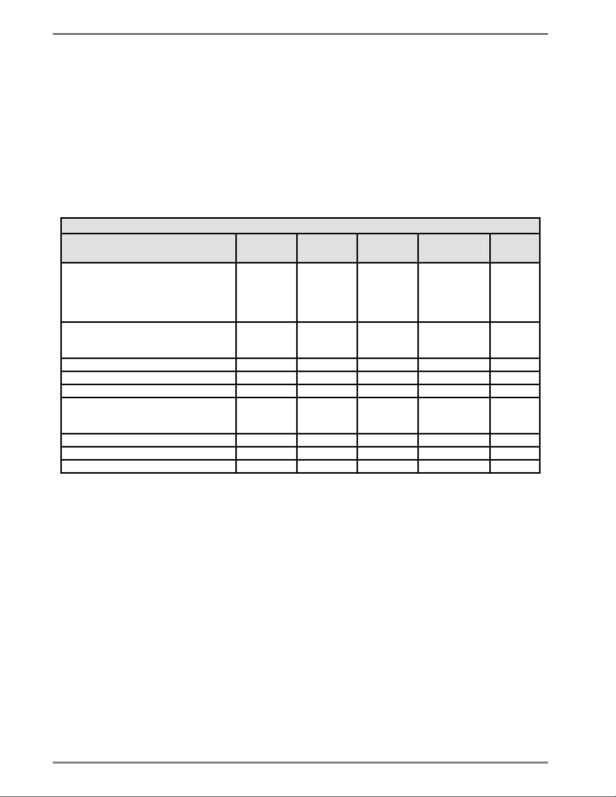
Designing Labels Using LDS Chapter 4
4.6.6.3 Embedded Bar Codes
Certain bar codes can be printed using various ratios and character spacing options. The
following table illustrates these options. See Chapter 8 for more detailed information on
designing label formats using bar code symbols. Some bar codes do not require a CGN
value and should be omitted by entering the comma delimiter.
For Example: If a TCI of 40 is selected the CGN will be omitted by entering nothing for the
CGN and surrounding the parameter with the comma delimiter.
1,200,200,10,40,,0,0,100,1
Bar Code Symbologies
SYMBOL RATIO HEIGHT SPACING FO **
Code 39 5
I 2 of 5
UPC / EAN * - 40 % 1 - 0123
UPC Readable * - 40 % 1 - 0123
Code 128 & UCC / EAN 128 * - 40 % 1 - 0123
Codabar
Code 93 - 2:1 1 - 0123
AS-10 - 2:1 1 - 0123
MSI (Modified Plessey) - 1:1 1 - 0123
CGN
VALUE
2
3
8
2 2:1 1 - 0123
3 3:1 1 - 0123
5 5:2 1 - 0123
2 2:1 1 - 0123
3 3:1 1 - 0123
5 5:2 1 - 0123
2:1 1 2 0123
3:1 1 2 0123
5:2 1 2 0123
8:3 1 3 0123
Table 4-7 CGN—Bar Code Symbologies
* These Symbols must use the CMX or CMY multipliers by 2 to produce an 80% ratio.
** The “FO” field represents the available Field Orientation or print rotation.
4.6.7 FO (Field Orientation)
This parameter defines the rotation of the format field on the label. The point of rotation is
determined from the Field Justification parameter.
0 0 degrees (normal rotation)
1 180 degrees (upside-down rotation)
2 270 degrees (right rotation)
3 90 degrees (left rotation)
4-16 324M/424M Operator’s Manual - 880026-1000
Page 45
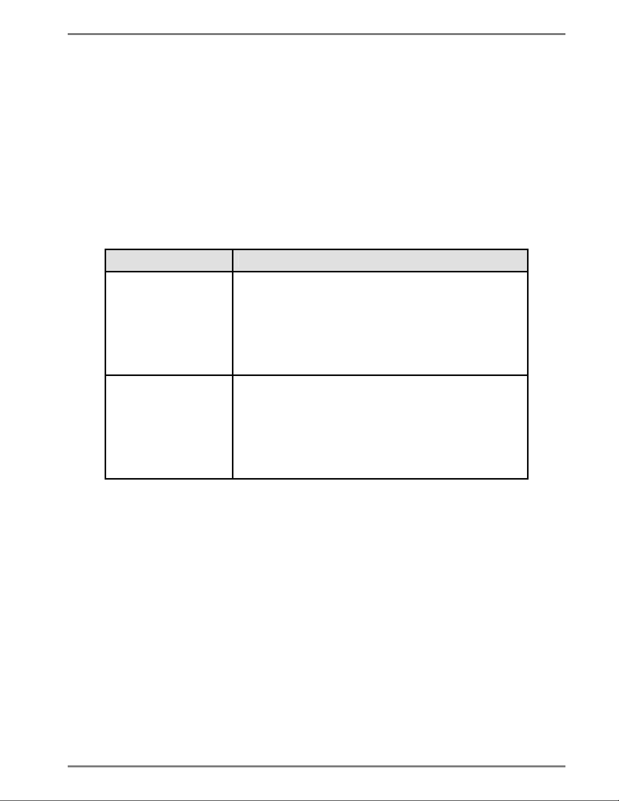
Chapter 4 Designing Labels with LDS
4.6.8 FJ (Field Justification)
This parameter defines the justification of the format field on the label.
0 Left Justified above the base-line
1 Right Justified above the base-line
2 Left Justified below the base-line
3 Right Justified bel ow the base-line
4 Centered above the base-line
5 Centered below the base-line
The table below shows how to obtain the proper character placement or starting positions
relative to the format field’s orientations and justifications.
ROTATION FIELD ORIENTATION and JUSTIFICATION
0 – Left justified above the base-line
1 – Right justified above the base-line
0 & 180 Degrees
90 & 270 Degrees
2 – Left justified below the base-line
3 – Right justified below the base-line
4 – Centered above the base-line
5 – Centered below the base-line
0 – Left justified above the base-line
1 – Right justified above the base-line
2 – Left justified below the base-line
3 – Right justified below the base-line
4 – Centered on the Y axis, right of X coordinate
5 – Centered on the Y axis, left of the X coordinate
Table 4-8 FO & FJ Character Starting Positions
4.6.9 CMX (Character Multiplier X Direction)
The CMX parameter multiplies each character in the X direction. The valid range is 1 to
65536. For bar codes with a FO of 0 & 180 degree rotation, the CMX would be the
multiplier while the CMY would be the actual height in thermal dots. For bar codes with a
FO of 90 & 270 degree rotation, the CMX would be the actual height in thermal dots while
the CMY parameter would be the multiplier.
4.6.10 CMY (Character Multiplier Y Direction)
The CMY parameter multiplies each character in the Y direction. The valid range is 1 to
65536. For bar codes with a FO of 90 & 270 degree rotation, the CMY would be the
multiplier while the CMX would be the actual height in thermal dots. For bar codes with a
FO of 0 & 180 degree rotation, the CMY would be the actual height in thermal dots while the
CMX parameter would be the multiplier.
324M/424M Operator’s Manual - 880026-1000 4-17
Page 46

Designing Labels Using LDS Chapter 4
4.6.11 CS (Character Spacing)
This parameter adjusts the spacing between each character. If this parameter is omitted,
then the default for the selected character generator (CGN) is used. The values (0-127) add
dots while (128-255) subtract dots. For example, a value of 4 would insert 4 dots between
the characters while a value of 131 would subtract 4 dots between the characters. Bar
codes have default spacing according to the indicated multiplier. Multiplying a text string will
not multiply the spacing between characters. This element may be used to properly space
the characters to create the desired printed effect.
4.6.12 TSP (Text Starting Position)
This parameter marks the starting position of the character in the text string to be used as
data. This is useful for allowing several fields to use sections of the same text string,
minimizing the amount of data transmitted. For example, for the text string 0123456789, a
TSP of 5 and a CC (Character Count) of 2 would print 45.
4.6.13 ,,, (Reserved Spaces)
These are spaces reserved for future use and nothing should be entered between the
comma delimiters.
4.6.14 AN (Attribute Number)
The AN parameter has four different effects. If set to a value of “0” the character spacing is
proportional. Reverse Text (white on black) is created by setting the AN to a value of “1”
and printing a black box on top of the text using the Line Draw function. (Special Note: The
AN parameter of the line field should also be set to a “1” for proper reverse imaging.) If the
AN parameter is set to a value of “2”, the character spacing will be fixed / non-proportional.
A setting of “3” will print both fixed/non-proportional character spacing and reversed text.
0 Proportional Character Spacing
1 Reverse Video
2 Fixed / Non-proportional Character Spacing
3 Fixed / Non-proportional Character Spacing and Reverse Video
8 True Reverse Video: Character cell = BLACK, Character = WHITE
4.7 Line Draw
It is possible to design lines into a label utilizing some of the elements of label format fields.
Specifically, a TCI value of “6” enables the line draw function. XB and YB provide a starting
position for a line draw. CMX and CMY provide length and thickness to a line. Other
elements not necessary to draw a line such as CC, CGN, FO, FJ, CS, and AN are ignored
by simply adding delimiters (commas) without values.
An example of two lines drawn on a label is shown in Error! Reference source not found..
This 3 x 3” label was designed for a 424M printer with a 300 DPI print head.
4-18 324M/424M Operator’s Manual - 880026-1000
Page 47

Chapter 4 Designing Labels with LDS
^D57 <CR>
2,1280,900,19,38,7,0,1,385,0,0 <CR>
1,340,750,,6,,,,600,25,,,,,0 <CR>
1,627,150,,6,,,,25,600,,,,,0 <CR>
^D56 <CR>
^D2 <CR>
Line <CR>
^D3 <CR>
Figure 4-5 Line Draw Sample
This is a list of the first label format field element mnemonics for the sample label in Error!
Reference source not found.:
TSN, XB, YB, CC, TCI, CGN, FO, FJ, CMX, CMY, CS, TSP, , , AN
1, 340, 750, , 6, , , , 600, 25, , , , , 0
324M/424M Operator’s Manual - 880026-1000 4-19
Page 48
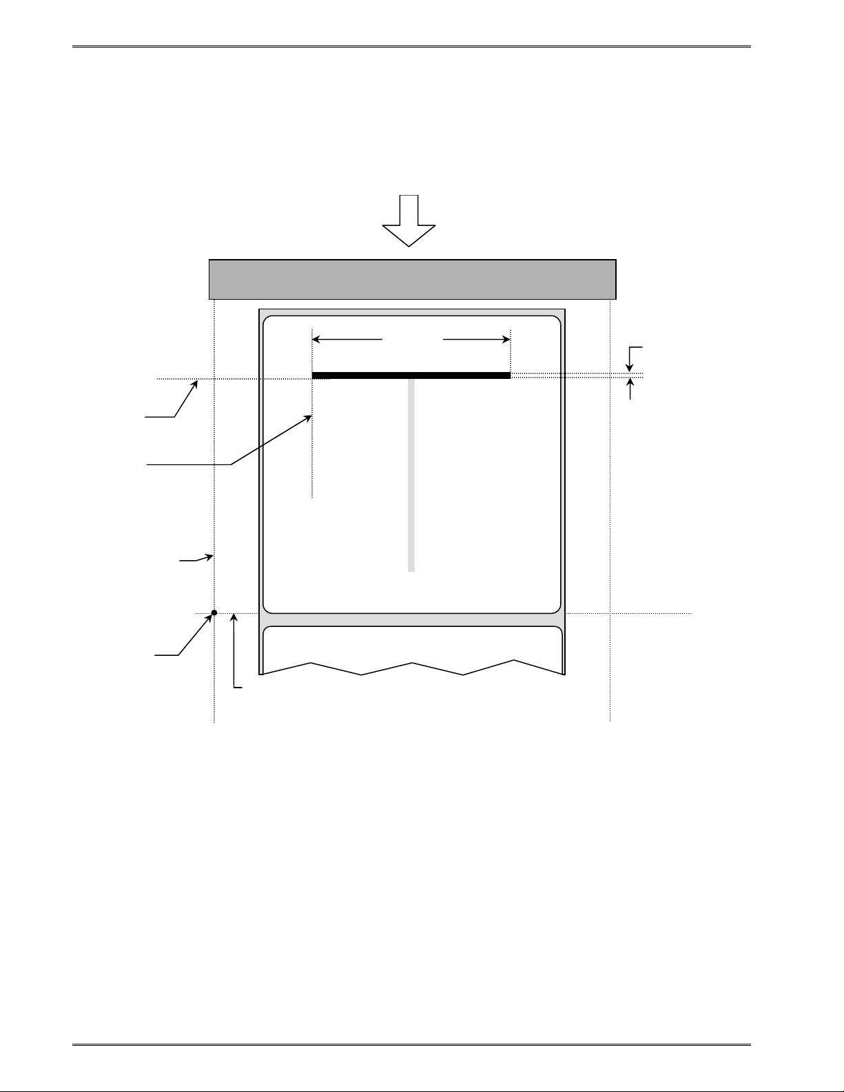
Designing Labels Using LDS Chapter 4
YB
XB
X beginning
This is the
origin; 1,1
Y beginning
Figure 4-6 Label Format Line Draw
TSN (Text String Number) The TSN parameter may point to any valid text string but it is a
good idea to always use “1” to make trouble-shooting formats easier. The text string that
the TSN is referencing must contain at least one character in order for a line to print
properly. “Line” was used in the example to clearly define the label format fields that contain
line values. However, it could have simply been one character such as a period “.”
XB (X Beginning Coordinate) The X and Y coordinates determine the start of the line
draw.
YB (Y Beginning Coordinate) The X and Y coordinates determine the start of the line
draw.
Feed Direction
4” PRINT HEAD
CMX
CMY
4-20 324M/424M Operator’s Manual - 880026-1000
Page 49

Chapter 4 Designing Labels with LDS
CC (Character Count) This element is not used in line draw. No value is necessary,
however, a comma needs to be entered to acknowledge the position.
TCI (Text Conversion Identifier) The TCI is always set to a “6” for line draw.
CGN (Character Generator Number) This element is not used in line draw. No value is
necessary, however, a comma needs to be entered to acknowledge the position.
FO (Field Orientation) This element is not used in line draw. No value is necessary,
however, a comma needs to be entered to acknowledge the position.
CMX (Character Multiplier X Direction) This element sets the length of a horizontal line
or the thickness of a vertical line.
CMY (Character Multiplier Y Direction) This element sets the length of a vertical line or
the thickness of a horizontal line.
CS (Character Spacing) This element is not used in line draw. No value is necessary,
however, a comma needs to be entered to acknowledge the position.
TSP (Text Starting Position) This element is not used in line draw. No value is
necessary, however, a comma needs to be entered to acknowledge the position.
,,, (Reserved Spaces) These are reserved for future use and no values should be
added between the commas.
AN (Attribute Number) This element should be set to “0” for line draw.
4.8 Reverse Video
The printer has the ability to produce Reverse Video by printing white text over a black
background. Two methods are used to produce this effect. The advantages and
disadvantages are covered in greater detail in the following two sections.
4.8.1 Reverse Video
The first method (Reverse Video) is to place text over a black box created with line draw.
When the label format defines print at the same coordinate twice the printer will not print
creating a reverse print effect when the Attribute Number (AN) is set to “1” for the Label
Format Fields defining the line draw and the text fields. The size of the box is not defined
by the text. Adjustment to the size of the box must be made by adjusting the line draw
coordinates.
324M/424M Operator’s Manual - 880026-1000 4-21
Page 50

Designing Labels Using LDS Chapter 4
^D57
6,1280,900,20,40,7,0,1,405,0,0
1,280,300,,6,,,,720,520,,,,,1
2,640,700,8,3,5,0,4,2,2,,,,,1
3,640,591,11,1,5,0,4,2,2,,,,,1
4,640,465,26,1,3,0,4,2,2,,,,,1
5,640,350,6,1,3,0,4,2,2,,,,,1
5,640,50,6,16,3,,4,5,150,,,,,0
^D56
^D2
Line
Microcom
Corporation
Thermal Printing Solutions
012345
^D3
Figure 4-7 Reverse Video Sample
Thermal Printing Solutions
Microcom
Corporation
012345
4.8.2 True Reverse Video
The second method (True Reverse Video) will create a white character in a black character
cell. The size of the black box surrounding the character will be determined by the
character cell. Adjusting the size of the box that is surrounding the text is not possible using
this method. It is possible to create a reverse video effect with barcodes using this method.
^D57
5,1280,900,0,0,7,2,0,1,0,0
1,640,700,8,1,5,0,4,2,2,,,,,8
2,640,591,11,1,5,0,4,2,2,,,,,8
3,640,465,26,1,3,0,4,2,2,,,,,8
4,640,350,6,1,3,0,4,2,2,,,,,8
4,640,50,6,16,3,,4,5,150,,,,,1
^D56
^D2
Microcom
Corporation
Thermal Printing Solutions
012345
^D3
Figure 4-8 True Reverse Video Sample
4-22 324M/424M Operator’s Manual - 880026-1000
Page 51

Chapter 5 Printer Commands
The model 324M and 424M printers have a large and versatile collection of control
commands to meet the special needs of labeling applications. Most of the commands use
the "^D" control sequence, however the printer also recognizes a selected number of other
control sequences.
For all commands listed in this manual, the printer will recognize the one character control
code ("Ctrl+D") or the two-character caret plus alpha character ("^+D+<CR>") sequence. In
other words, the same command may be generated by either holding the control (Ctrl) key
down and pressing the alpha character or by entering the two characters - the ^ (caret,
generated when the "Shift" key is pressed and then the "6" key) and then the appropriate
alpha key (upper and/or lower case).
Unless specified otherwise, commands are entered by sending the ^Dxx command where
xx is the command number. The ^D commands are terminated by either issuing a carriage
return after the command or by issuing another command and/or control code. Some
commands load data or control numbers and are preceded by the ^Axx command. The xx
specifies the value and/or control number for the associating ^D command. The ^D
commands should precede or follow the actual format layout. They should be placed before
the ^D57 or just before the ^D3 print command.
To protect against errors, in situations where the two-character caret and alpha sequences
are used exclusively as printer commands, the control character recognition may be
disabled. This is accomplished by using the ^D93 command or by using the ^D21
command to setup Soft Switch #1 Bits #1 & #2 (See 5.2.2.1).
Some mainframe and mini-computers cannot use the ASCII "^" character. In these cases,
substitute the ASCII pipe symbol ("|") or use the one-character control code representation.
5.1 Special Printer Control Codes
To perform special functions, the printer uses the following control characters. All other
control characters will be ignored. Some of these instructions are also accessible through a
"^D" command sequence and will be noted as such.
^A Accumulator Mode: Used to supply the parameters for the ^D commands.
These parameters must be positive integers and are generally decimal
numbers but may be entered as binary if the ASCII "B" precedes the value or
parameter. For example, "^AB00000001^D21 <CR>" may also be entered as
"^A1^D21 <CR>" as well.
^B Text Entry Mode: Instructs the printer to enter printable text entry mode.
This command (or the preferred "^D <CR>") must be sent before the text
string information. This command is the equivalent of the "^D<CR>" sequence
but does not require the carriage return (^B text string data). Because the
"control B" is shorter, it is easier to use in direct terminal mode. In general it is
324M/424M Operator’s Manual - 880026-1000 5-1
Page 52

Printer Commands Chapter 5
better to use the ^D2 command sequence inside a file or program to assist in
trouble-shooting the format.
^C Print: Starts the print cycle or batch. This command is the equivalent of the
"^D3<CR>" command sequence but does not require the carriage return.
Because the "control C" is shorter than the ^D3 command sequence it is
easier to use in direct terminal mode. In general the ^D3 sequence is better to
use inside a format and/or program to assist in trouble-shooting the format.
^D Command Mode: Used to issue commands to the printer. This command is
normally preceded by the ^A sequence. The ^D commands must be
terminated with a carriage return or another command sequence
(^A9^D73^D3<CR> is the same as ^A9^D73<CR> and ^D3<CR>).
^E Printer Enquiry: This command is used to attain the current status or
operational state of the printer. The "^E" does not require a carriage return
and is the equivalent to the "^D5<CR>" command sequence. If Binary
Compression is enabled (default setting) the ^E and ^D5 commands will not
function. Five NULL characters (HEX 00) followed by a SOH (0x01) (00 00 00
00 00 01) are required to get the printer's immediate when configured for
binary use. The serialized ^D5 command will continue to function while in
binary compression mode if the printer is idle or not in an error. It is
recommended that the five NULLs method is used to request printer status as
it functions with a printer in binary compression, binary compression disabled,
or if the printer is in an error condition. See 5.1.1for additional information
regarding the Printer Enquiries.
^M Terminate Text or Data String: This command is the equivalent of the
carriage return character and is used to terminate commands and format lines.
^H Delete: This control code is used to delete the last printable character when
communicating to the printer through a keyboard via a terminal. The ^H is the
equivalent of the "Backspace" key on the keyboard.
^K Print Test Pattern: Used to generate a test pattern, which consists of a
series of diagonal lines. The pattern is helpful in determining the condition of
the thermal dots on the print head. The ^K code is the equivalent of the "^D11
<CR>" command sequence.
^L Form Feed: Used to feed one blank form based on the previous format
configuration parameters. This command is the equivalent of the "^D12
<CR>" command sequence.
^Q XON: Instructs the printer to send data or resume sending data.
^S XOFF: Instructs the printer to stop sending data.
5 NULLS + 01: The 5 NULL method commands are a way to pass commands to the
printer even when the printer is configured in binary compression mode. The
command is sent to the printer as HEX characters; 00 00 00 00 00 01 are sent
5-2 324M/424M Operator’s Manual - 880026-1000
Page 53

Chapter 5 Printer Commands
to the printer in order to issue the command. This command is used to
request the printer's status and is very similar to the ^E command. The
biggest difference between this command and the ^E is that when printers are
configured for binary compression (D23 - SW3 bit 7), which is required if
saving graphics, the ^E will not function. This means that if the printer is going
to be using binary compression, the 5 NULLs method should be used to
request status instead of the ^E command.
5 NULLS + 02: The NULL method commands are a way to pass commands to the
printer even when the printer is configured in binary compression mode. The
command is sent to the printer as HEX characters; 00 00 00 00 00 02 are sent
to the printer in order to issue the command. This command is used to cancel
pending jobs/commands and to remotely clear errors returning the printer to
an idle >READY< state. If the condition causing the original error condition
still exists, sending new jobs will cause the printer to go back into an error
condition. This command simply provides the ability to remotely clear error
conditions and return the printer to a state that allows normal communication.
5 NULLS + OF: The 5 NULL method commands are a way to pass commands to
the printer even when the printer is configured in binary compression mode.
The command is sent to the printer as HEX characters; 00 00 00 00 00 0F are
sent to the printer in order to issue the command. This command instructs the
printer to exit the temporary binary mode switch. If a printer has been
configured to use binary compression mode using the soft switch command
(D23 - SW3 bit 7), the 5 NULLs + 0F method will be ignored when issued.
0F + NULLS: The 5 NULL method commands are a way to pass commands to the
printer even when the printer is configured in binary compression mode. The
command is sent to the printer as HEX characters; 0F 00 00 00 00 00 are sent
to the printer in order to issue the command. This command provides a
temporary switch into binary compression mode without having to have the
printer configured for binary compression (D23 - SW3 bit 7) mode. This is
helpful when placed just before a graphic file. The printer will continue
processing the data as binary data until instructed to exit the temporary binary
mode (5 NULLs + 0F).
5.1.1 Enquiry Responses
It is important for the host computer to know the status of the printer as labels are being
produced. This facilitates security in the system and flags electrical, mechanical, and
functional error conditions. Enquiries also aid the system designer in adjusting the pace of
the printer with that of the operator.
The printer returns enquiry responses to the host in two different modes depending on how
Software Switch#1 is configured.
Text Mode: The response is sent to the host as text as shown in Table 5-1. The strings
are sent out the active communication port with a CR LF separating each one. The end of
the response is terminated with an extra CR LF.
324M/424M Operator’s Manual - 880026-1000 5-3
Page 54

Printer Commands Chapter 5
Byte Mode: The response is sent to the host as a hexadecimal number (byte) as shown in
Table 5-1. Each string is represented by a single byte with nothing separating them. The
end of the response is terminated with a FF character.
Text Mode Response Byte Mode
Response
>RESTARTED< 1A Printer has been reset
>READY< 06 Normal condition
>CUTTER ERROR< 07 Cutter cannot rotate
>TAKE LABEL< 16 Printer is waiting for label to be taken
>LOW STOCK< 19 Media supply is low or out
>INPUT 1< 0E Input sensor #1 active
>INPUT 2< 21 Input sensor #2 active
>TRAY FULL< 09 Printed label tray is full
>PRINTER PAUSED< 10 Printer is paused
>TOF ERROR< 1F Top of Form is not sensed properly
>OVER VDD< 1E VDD voltage is out of operational range
>UNDER VDD< 1C VDD voltage is out of operational range
>OVER TEMP< 1D Print Head is too hot
>DATA ERROR< 15 Communication error
>STOCK NOT LOADED< 22 Printer power on without media installed
>BUTTON PRESSED< C0 Print button configured to report
>CODE 12< 23 CRC value does not match stored value
Table 5-1 Enquiry Responses
Definition
message when pressed
5.2 Printer Configuration Commands
The following commands are used to set up printer configuration. Most of these commands
are non-volatile and, therefore, do not need to be present unless changes are desired.
Note: When the printer is in the DEFAULT MODE, factory settings control printer operation.
This provides a starting point for re-establishing communication with the printer so that user
settings can be sent to the printer. The statistics label printed when the printer is entered
into the DEFAULT MODE reflects current user settings, not factory default settings.
5.2.1 Baud Rate
This non-volatile command changes the serial port communication speed.
Note: Unless otherwise noted, the factory default baud setting is 115,200. The baud rate
will be temporarily set to 115,200 when the printer is in the Diagnostic Mode if the user
setting is different. The user set baud rate will resume after a "soft reset" (^D32) or cycling
the power to the printer.
5-4 324M/424M Operator’s Manual - 880026-1000
Page 55

Chapter 5 Printer Commands
^A ^D COMMAND
20
0 110 bps
1 150 bps
2 300 bps
3 600 bps
4 1,200 bps
5 2,400 bps
6 4,800 bps
7 9,600 bps
8 19,200 bps
9 38,400 bps
10 57,600 bps
11 115,200 bps
5.2.2 Software Switches
The Software Switch settings are non-volatile. The DIP Switch commands may use either
^A (decimal) or ^AB (binary) values. Since each bit represents a setting for the printer, the
soft switches are always reported as binary.
Example: ^AB10100001^D21<CR> configures serial port #1 for text equivalent enquiry
responses, accept control codes, disables echo, and enables XON/XOFF flow control.
^AB12345678 (each bit is represented by a numeric position number)
5.2.2.1 Software Switch #1
^AB ^D COMMAND
XX 21 Change SW1: Software Switch #1.
^AB12345678 (each bit is represented by a numeric position number)
Position:
1,2 Enquiry Response: This determines what the printer will send back in
response to an enquiry command.
00 = Control Codes
10 = Text Equivalent
3 Control Codes: This position sets how the printer handles incoming
control codes.
1 = Ignore Incoming Control Codes
0 = Accept Incoming Control Codes
4 Port #1 Parity Selection: Sets the printer port #1 parity for serial
communication.
1 = Odd Parity
0 = Even Parity
324M/424M Operator’s Manual - 880026-1000 5-5
Page 56

Printer Commands Chapter 5
5 Port #1 Parity Enable: Turns printer port #1 parity ON or OFF for
serial communication.
1 = Disable Parity (NONE)
0 = Enable Parity
6 Echo: If this feature is enabled, the printer will echo all received
characters to the serial port.
1 = Enable
0 = Disable
7 Number of Data Bits: Sets the printer's serial port to use either 7 or 8
data bits.
1 = 8 Data Bits
0 = 7 Data Bits
8 XON/XOFF Flow Control: Sets software flow control handshaking.
CTS/RTS hardware handshaking is always enabled.
1 = Enable
0 = Disable
5.2.2.2 Software Switch #2
^A ^D COMMAND
XX 22 Change SW2: Software Switch #2.
^AB12345678 (each bit is represented by a numeric position number)
Position:
1 Clear Text Function: If enabled, all variable text strings will be erased
when the ^D<CR> is processed.
1= Enable
0 = Disable
2 >RESTARTED< Response: If the printer has been reset and this
switch has been enabled, the printer will respond with the
>RESTARTED< message for the first enquiry ONLY, to denote the
reset condition and then >READY< with following enquiries.
1 = Enable (>RESTARTED< on first inquiry then >READY<)
0 = Disable (Always responds with >READY<)
3 Button Use: If set to a "1", the printer will disable the Print Button.
1 = Disable
0 = Enable
4 Print Button: Defines the function of the Print Button. If set to a "0",
the button can be used for feeding labels but the print function is
disabled.
1 = Label FEED & PRINT
0 = Label FEED only
5-6 324M/424M Operator’s Manual - 880026-1000
Page 57

Chapter 5 Printer Commands
5 Power-ON Format Type: Determines whether to use a saved format
file or a standard ROM format. User downloaded Label FORMAT files
are saved in non-volatile FLASH memory. Any of these FORMATs may
be used for the Power-ON label. When SW2, 5 = 1, the format is
selected by SW2 switch positions 6, 7, and 8.
1 = Power-ON label is selected by SW2, 6, 7, and 8
0 = Power-ON label is standard format
6,7,8 Power-up Format: These switches work in conjunction with switch
location 5 above. They determine which stored format is loaded at power-up.
The printer can be instructed not to load a format at power-up by setting all
three switches to 0.
000 = No Power-up Format
001 = ROM or Saved Format File 1
010 = ROM or Saved Format File 2
011 = ROM or Saved Format File 3
100 = ROM or Saved Format File 4
101 = ROM or Saved Format File 5
110 = Rom or Saved Format File 6
111 = ROM of Saved Format File 7
5.2.2.3 Software Switch #3
^A ^D COMMAND
XX 23 Change SW3: Software Switch #3
^AB12345678 (each bit is represented by a numeric position number)
Position:
1 Extended ASCII: Controls whether characters over HEX 7F will be
processed.
1 = Don't process input characters greater than 7F
0 = Process input characters greater than 7F
2 INPUT 1 Active State: This bit determines whether the INPUT 1 sensor
must see an object or not to send back the >INPUT 1< response. A
setting of 1 (active LOW) will report the >INPU T 1< message of no
reflection is detected. A setting of 0 (active HIGH) will report the
>INPUT 1< message of a reflection is detected.
1 = Send >INPUT 1< active LOW
0 = Send >INPUT 1< active HIGH
3 Response After Print: If enabled, an enquiry response will be sent
through the serial communications port #1 (COM1) after every print.
1 = Enable
0 = Disable
324M/424M Operator’s Manual - 880026-1000 5-7
Page 58

Printer Commands Chapter 5
4 INPUT 2 Active State: This bit determines whether the INPUT 2 sensor
must see an object or not to send back the >INPUT 2< response. A
setting of 1 (active LOW) will report the >INPU T 2< message of no
reflection is detected. A setting of 0 (active HIGH) will report the
>INPUT 2< message of a reflection is detected.
1 = Send >INPUT 2<active LOW
0 = Send >INPUT 2< active HIGH
5 Accept "|" for Ctrl: Sets whether the "pipe" character will be
interpreted the same as the "Ctrl" key. The "pipe" character is the
<SHIFT> + \ key.
1 = Disable
0 = Enable (<|> key functions as <Ctrl> key)
6 Accept "^" for Ctrl: Sets whether the "caret" character will be
interpreted the same as the "Ctrl" key. The "caret" character is the
<SHIFT> + 6 key.
1 = Disable
0 = Enable (^ key functions as <Ctrl> key)
7 Binary Compression: If enabled, the printer will accept downloaded
binary compressed font and/or graphic files. ^E and ^D commands will
not function. (See 5.1)
1 = Enable Binary Mode
0 = Disable Binary Mode
8 Detect Black Line on Power-up: If enabled, the printer automatically
feeds labels on Power-up to determine the proper ^D91 value.
1 = Enable
0 = Disable
5.2.2.4 Software Switch #4
^A ^D COMMAND
XX 24 Change SW4: Software Switch #4.
^AB12345678 (each bit is represented by a numeric position number)
Position:
1 Slashed Zeros: If enabled, the printer will print a slash through the
embedded zero ("0") characters.
1 = Enable
0 = Disable
2 External Print Request: (Call Microcom for more information.)
1 = Enable
0 = Disable
5-8 324M/424M Operator’s Manual - 880026-1000
Page 59

Chapter 5 Printer Commands
3 Stock Out function: Enable this function to get a >LOW STOCK<
message when the printer runs out of stock. When this is disabled, the
printer will not report a stock out condition.
1 = Disable
0 = Enable (stock out detection gives >LOW STOCK<)
4 Auto-Size on Power-up: When enabled, the printer automatically sizes
the label to determine the appropriate format header values on powerup. The printer will then use these values on all subsequent label
formats. Refer to the ^D39 command for additional information.
1 = Enable
0 = Disable
5,6,7,8 Code Page Selection: Positions 5 through 8 are used to select from
the available code pages stored within the printer.
See Chapter 9 for more details
0000 = Not Decoded (Default) 1000 = 852
0001 = Danish 1001 = French
0010 = 860 1010 = 863
0011 = Spanish 1011 = Swedish
0100 = 850 1100 = 437
0101 = German 1101 = Italian
0110 = 865 1110 = English - UK
0111 = Swiss 1111 = English – US
5.2.2.5 Software Switch #5
^A ^D COMMAND
XX 25 Change SW5: Software Switch #5.
^AB12345678 (each bit is represented by a numeric position number)
Position
1 = Enable (Single Button Error Clear)
0 = Disable (Reprint and Align)
:
1 Single Button Press Clear: If enabled, error conditions are cleared
with a single press of the print button after reloading the printer with
more media. If this function is disabled, pressing the print button clears
the error condition, prints the pending job, and reenters the previous
halting error state. The button must be pressed and held during printing
in order to exit the error routine. This is used to reprint the pending job
until the print realigns before continuing.
324M/424M Operator’s Manual - 880026-1000 5-9
Page 60

Printer Commands Chapter 5
2 >BUTTON PRESSED< status enable: When enabled, pressing the
button will cause the printer to report the >BUTTON PRESSED< or
0xC0 depending on the printer's ^D21 response mode configuration.
This is typically used on systems that preload a batch of jobs to the
printer but wait on the >BUTTON PRESSED< message before sending
the print command.
1 = Enable >BUTTON PRESSED<
0 = Disabled
3 Type of Top Of Form Sensor: The leading edge of the label stock can
be sensed using either a reflective sensor or a transmissive sensor.
The correct type of sensor is determined by the printer hardware
configuration being used.
1 = TOF is TRANSMISSIVE
0 = TOF is REFLECTIVE
4 Enable Power ON TOF: This bit controls whether or not the printer will
do an automatic Top Of Form (TOF) when it is turned ON.
1 = Enable Power-ON TOF
0 = Disable
5 Enable Button TOF: This bit determines whether the GREEN button
functions as a Top Of Form or as defined by SW#2, bit 4. The button is
always configured to clear error conditions.
1 = Button is TOF
0 = Button is PRINT
6 Enable AutoLoad: This bit determines whether the AutoLoad function
is ON or OFF. When Autoload is enabled and a no media to media
transition is detected by the printer's internal transmissive sensor, the
printer will step the pulled media into the printer and perform either a
TOF or a Form Feed depending on SW#5, bit 7 configuration.
1 = AutoLoad is ON
0 = AutoLoad is OFF
7 Type of AutoLoad: This bit determines whether the AutoLoad function
uses the Top Of Form sensor (TOF), or if it uses the Form Feed
technique.
1 = AutoLoad + TOF
0 = AutoLoad + FF
8 General Purpose Mode: If enabled, the printer will enter a special
mode of communications using the Ethernet port.
1 = Enable General Purpose Mode
0 = Disable General Purpose Mode
5-10 324M/424M Operator’s Manual - 880026-1000
Page 61

Chapter 5 Printer Commands
5.2.2.6 Software Switch #6
^AB ^D COMMAND
XX 26 Change SW6: Software Switch #6.
^AB12345678 (each bit is represented by a numeric position number)
Position:
1 Enable Test Pattern or Halt on >TRAY FULL<: This bit is used to
define whether a test pattern will print, or if the printer will halt on a
>TRAY FULL< error when used with the optional catch tray. This bit
will determine the printer's response when pin 4 of P17 is active.
1 = >TRAY FULL< condition.
0 = A test pattern is printed.
2 Enable Auto-Header: This bit determines whether the Auto-Header
function is ON or OFF. This command provides similar functionality of
other printer manufacturers that specify exact placement and location of
blackline media used for registration. This command is a specialty
media handling command that works when the correct media is used.
Please contact your Microcom Corporation representative if you have
any questions regarding the use of this command. When enabled the
printer will autoload and determine the correct header parameters for all
subsequent formats based on the loaded media except for HFM which
is the only parameter that must be included with the format header.
The above values may be changed via the appropriate ^D command
with the change being permanent until another Auto-Header or another
^D command changes them.
After executing the Auto-header command, the values that the printer
will use for the header may be observed using the ^D148 command.
When stock is initially loaded the printer will do an auto header to
determine the correct header parameters. After this, when stock is
loaded, the printer will just advance the stock to the correct printing
position wasting the first label unless stock is loaded after a stock out
condition. Then the printer will pull the stock in and print on the first
label and clear the error.
1 = Enable Auto-Header
0 = Disable Auto-Header
3 Enable Pre-Stock-Out feature: This command supports the PSO
option and is used to detect stock out errors before entering the printer.
Once enabled, when the PSO (>INPUT 1<) sensor goes active the
printer will finish printing the current label, not cut it (if using a cutter
command), then feed he stock until it clears the dot row plus 1/2". At
this point the normal stock out function will be active and the printer
status will respond with: >LOW STOCK<>INPUT 1< (if the polarity of
input one is set correctly).
324M/424M Operator’s Manual - 880026-1000 5-11
Page 62

Printer Commands Chapter 5
If the length of the label happens to be larger than the distance from the
Pre-Stock-Out sensor to the dot row (^D146 command) the printer will
not be able to completely finish printing the last label. Other than this,
the operation of the printer will be the same as above.
1 = Enable Pre-Stock-Out feature
0 = Disable Pre-Stock-Out feature
4 Enable >STOCK NOT LOADED< Response: When enabled, the
printer will return >STOCK NOT LOADED< or 0x22 (depending on the
^D21 response mode configuration) to status requests if media is not
detected in the printer at powerup. The status message will continue to
be reported until media is installed in the printer. This message will
only be reported if media is not detected by the internal sensors
following a power on, reboot command (^D143), and/or restart (^D32)
commands.
1 = Enable >STOCK NOT LOADED< response
0 = Disable >STOCK NOT LOADED< response
5 48-466 Emulation Mode: A special limited 466/48-466 LDS
compatibility mode has been developed for the X24/X24M code base.
The objective of this compatibility mode is to allow applications that use
formats and/or commands developed for a Model 48-466 printer to be
sent to a 203 dpi X24 or X24M Model printer with little or no changes
required. This command allows the printer to enable a limited 48-466
emulation feature of the printer. When enabled, the printer will process
a 48-466 data stream and convert the data stream for proper operation
on an X24M printer. The emulation mode uses a lookup table for fonts
stored in flash and does not use the TCI 1 embedded fonts while this
mode is enabled. Please note that the X24 products store fonts in 0
/180 degree rotation and in 180/270 degree rotation. The odd memory
slots denote 0 or 180 degree rotation fonts while the even memory slots
denote 90/270 degree rotated fonts. The flash memory slot locations
are shown below:
48-466 TCI = 1, CGN # X24 Flash Memory Slot
1 1 and 2
2 3 and 4
3 5 and 6
4 7and 8
5 9 and 10
6 11 and 12
7 13 and 14
8 15 and 16
Table 5-2 48-466 Emulation Fonts
5-12 324M/424M Operator’s Manual - 880026-1000
Page 63

Chapter 5 Printer Commands
The 48-466 emulation supports unique 48-466 command operations
and will process the data in the same way when technically possible.
These unique operations are briefly discussed below. Please consult
the Model 48-466 Operators Manual for additional information regarding
the command operation.
a) The printer supports the CGN lookup as defined above and in the
48-466 Operators manual when the emulation command is enabled.
b) The 48-466 graphic structure is used when the emulation command
is enabled and discussed in greater detail the 48-466 Operators
manual.
c) The ^D59 command allows format slots 121 to 128 to be overwritten
to when the emulation command is enabled.
d) The ^Ax^D125 command controls the location of the euro character
as provided in the model 48-466 printers. The euro character which
by default is mapped to location 0xE3 (227 decimal) can be moved
to another location specified by the x if x>0. If x=0 no remapping will
take place and the euro will stay at location 0xE3. Also if the printer
must be configured to use a code page other than the default (0000)
code page.
The 48-466 and X24 code bases are not fully compatible, so the
emulation does have some limitations. The known limitations are briefly
mentioned below:
a) The 48-466 data stream should not use an Attribute Number of 2
(fixed/non-proportional) which is the seventeenth parameter. It is
not technically possible to emulate this model 48-466 feature.
b) The CS value used in conjunction with the AN set to a 2 to produce
a negative kerning effect should be removed and the field defaulted.
This is the 11th field defined in the format lines.
c) Fields that were using an AN of 2 and CS for negative kerning may
require that their placement coordinates are adjusted to produce the
same outputs.
Once these changes are made, the resulting data may be sent to a 48466 and 424M printer to produce the same printed image in most
cases.
1 = Enable 48-466 Emulation Mode
0 = Disable 48-466 Emulation Mode
324M/424M Operator’s Manual - 880026-1000 5-13
Page 64

Printer Commands Chapter 5
6 Select GP I/O Hardware Mode: This command is used to select
from the various General Purpose I/O modes the printer supports.
0 = Enable Custom General Purpose I/O Hardware. This mode is a
custom solution developed for a specific customer and is not intended
to be used by other users.
1 = Enable General Purpose I/O Hardware. When this command is
enabled, the printer provides the ability to report the current status of 4
additional inputs accessed through the P17 connector on the PCB,
report the status of 4 additional outputs accessed through the P21
connector on the PCB, to change the status of the outputs, and to
configure the inputs to generate immediate errors.
GP INPUTS:
The P17 connector is used for the GP inputs. These inputs are active
high (24VDC) and may be independently controlled.
The ^D150 command is used to report the current status of the inputs.
When issued, the printer will send the host the current status of the 4
general inputs in the form of “>IO 0nH< where “n” is a hex number from
0 to F.
Example: A status of >IO 05H< would indicate that inputs 1 and 3 are
active (24v) and that inputs 2 and 4 are inactive (0v); 05H =
0101(binary).
The ^D151 is a nonvolatile command used to set which GP inputs are
configured to cause an immediate error when active. An immediate
error will immediately stop printing and go into an error condition. Once
the input is inactive, the “error” would need to be cleared before the
printer will continue. The ^D29 statistical listing reports the GP inputs
that are configured to generate error conditions when active and are
listed under the “ERROR INPUT: 0nH” with the value for “n” equaling
the HEX value of the inputs. The inputs equal a binary number with the
inputs in the following order; 4321.
Command Syntax:
^D151<CR>0n<CR>
n = the hex value from 0 to F.
Example: If the application wanted to configure inputs 1 and 3 to
generate error conditions when active, a ^D151<CR>05<CR>
command (the <CR> indicates carriage return characters) would be
issued. The printer ignores the LF characters, so a <CR+LF> is
interpreted as a <CR> as well) would be sent to the printer.
5-14 324M/424M Operator’s Manual - 880026-1000
Page 65

Chapter 5 Printer Commands
GP OUTPUTS:
The P21 connector is used to provide 4 general purpose outputs.
These outputs provide 24V and may be used to provide the voltage
needed to power the GP INPUTS.
The ^D69 command is used to read and report the current status of the
GP Outputs in the form of “>IO 0nH< where “n” is a hex number from 0
to F. The outputs equal a binary number with the values in the
following order; 4321.
Example: A status of >IO 05H< would indicate that outputs 1 and 3 are
active (24v) and that outputs 2 and 4 are inactive (0v); 05H =
0101(binary).
The ^D68 is a nonvolatile command used to enable which GP outputs
are active. The outputs are entered in as a HEX value that is equal to a
binary number with the outputs in the following order; 4321.
Command Syntax:
^D68<CR>0n<CR>
n = the hex value from 0 to F.
Example: If the application wanted to configure outputs 1 and 3 active,
a ^D68<CR>05<CR> command (the <CR> indicates carriage return
characters) would be issued. The printer ignores the LF characters, so
a <CR+LF> is interpreted as a <CR> as well) would be sent to the
printer.
NOTE: A status request (^E, ^D5, or 5 NULLs 01) will never show the
status of the outputs while a status request will show the input status if:
1) GP I/O is enabled AND
2) One or more bits have been configured to generate errors when
active AND
3) One or more of those halting bits have gone active and have
produced an error that has not been cleared.
NOTE: If the printer is not in the general purpose I/O mode, the inputs
status may still be read with the ^D150 command but the outputs
cannot be read (or written to) with the ^D69 or ^D68 commands.
NOTE: If an input has caused an error to be generated, then goes
inactive, and another print request received before the error is cleared,
the printer will not print and will remain in the error state. A status
request will show the active error inputs. This condition will remain until
the error is cleared.
NOTE: Default power up will disable I/O mode.
324M/424M Operator’s Manual - 880026-1000 5-15
Page 66

Printer Commands Chapter 5
The P17 and P21 connectors are 8 pin MTA50 AMP part number
#1445350-8 and Microcom Corporation part number 510188-0008.
The pin out is as follows (the square pad denotes pin one on the PCB):
Connector P17 is the input port.
1 = ground
2 = g/p input 1
3 = ground
4 = g/p input 2
5 = ground
6 = g/p input 3
7 = ground
8 = g/p input 4
All inputs are active high. 24.0 VDC = high 0.0 VDC = low
Connector P21 is the output port.
1 = ground
2 = g/p output 1
3 = ground
4 = g/p output 2
5 = ground
6 = g/p output 3
7 = ground
8 = g/p output 4
All outputs are active high. 24.0 VDC = high 0.0 VDC = low
P17
INPUTS
Figure 5-1 General Purpose Hardware Inputs and Outputs
Pin 1
7 Select PIC Mode: This command is used to select from the various PIC
modes the printer supports. The PIC code is dedicated to the take-up
motor or the cutter.
0 = Select Cutter PIC mode of operation. When this mode is
selected the printer will power and energize a cutter when the cutter
enable command (^D99 or ^D111) is issued after a print job
Pin 1
P17
OUTPUTS
5-16 324M/424M Operator’s Manual - 880026-1000
Page 67

Chapter 5 Printer Commands
1 = Select Take-up PIC mode of operation. When this mode is
selected the printer will energize a DC motor to be used in a rewind or
take up capacity. Unless the printer is properly configured with a takeup motor and correct take-up motor specific PIC, this mode should not
be enabled because it could potentially damage the cutter.
8 Always 0
5.2.3 Set Communication Port Selection Commands
The 324M and 424M printers have 3 different serial communication ports on the rear panel:
1) RS-232D 115,200 bits/sec, max.
2) USB 12Mbits/sec
3) Ethernet (option) 10Mbits/sec or 100Mbits/sec
Only one of the 3 serial ports can be active at any time, but all 3 cables can be connected to
the printer at the same time. In cases where more than 1 cable is connected, the printer
follows specific rules to determine which serial port is the active port when power is applied.
5.2.3.1 Set Serial Port Source Command (Non-volatile- ^D108)
This command sets which serial port will be used the next time the printer is turned ON. The
324M/424M printer has three serial data ports on the rear panel: RS-232, USB, or Ethernet.
Only 1 port can be active at any given time. The D108 command sets how the printer
selects the active serial port the next time the printer is powered ON. Settings made with
D108 are saved in the printer's system parameters and are used to select the serial port on
power-up.
^A ^D Command
X 108 Serial Port Source (Non-volatile)
0 AutoScan: When the printer powers up, it will scan the USB and RS-232
ports and select the "HOT" port. The USB port will be the HOT port if the USB
cable is connected between the printer and a PC that is powered "ON." The
RS-232 port will be the HOT port if the USB cable is not plugged in and a
character comes in on the RS-232 port. The printer will continue to scan both
ports until one or the other condition is satisfied.
1 Ethernet: This command tells the printer to use the Ethernet port the next
time it powers up.
5.2.3.2 Set Serial Port Source Command (Volatile - ^D109)
This command is similar to the ^D108 command, except the ^D109 command immediately
switches between the 3 serial ports without the need to cycle power. Settings made with
^D109 command are NOT saved on power-down. The printer returns to the original port
setting on the next power-ON.
Note: The AutoScan option is not available with the ^D109 command.
^D Command
^A
X 109 Serial Port Source (volatile)
0 RS-232
1 USB
2 Ethernet
324M/424M Operator’s Manual - 880026-1000 5-17
Page 68

Printer Commands Chapter 5
5.2.4 Contrast Adjustment Commands
These commands are used to adjust the darkness of the label print. Print quality will vary
not only with different label stocks, sometimes even in different batches of the same label
stock. It is highly recommended that contrast adjustments be maintained at minimum
settings to achieve desired print quality. Higher contrast settings will reduce the life of the
print head.
5.2.4.1 Adjust Contrast Window (Volatile - ^D35)
This command is useful for adjusting contrast for specific label formats where different label
media is used on a single printer. The command can be entered into specific label formats
rather than affecting print contrast on all label formats.
^A ^D COMMAND
XX 35 Adjust Contrast Window: This is a volatile command used to adjust the
contrast window. The range is 1 to 9 of the base (^D36).
5.2.4.2 Adjust Contrast Base (Non-volatile - ^D36)
This command is used to adjust overall contrast on all formats.
^A ^D COMMAND
XX 36 Adjust Contrast Base: This non-volatile command is used to skew the entire
contrast window (^D35). This command has a ^A range of 10 to 200%.
5.2.5 Slice Buffer Size and Set Starting Slice Number Commands
^A ^D Command
XX 92 Set Starting Slice Number: This non-volatile command adjusts the number of
slices (dot rows) generated before the printer starts moving the label stock.
The default is set to 67% of the slice buffer size. Anytime the size of the slice
buffer is changed (^D94 command), the Starting Slice # is also changed
automatically to a value that is 67% of the new slice buffer size. The
maximum number of slices (XX) is dependent on the size of the slice buffer
(^D94) command.
"XX" can be any integer value up to a maximum of the number of slices in the
Slice Buffer. If a value for "xx" is entered that is too large for the print head,
the printer will respond with the correct maximum value for the head size
currently in use.
Table 5-2 below lists the default Starting Slice Number for various heads and
buffer sizes.
This command is used together with the ^D94 command to fully set up the
slice buffer function.
5-18 324M/424M Operator’s Manual - 880026-1000
Page 69

Chapter 5 Printer Commands
Print Head ^A2^D94 ^A3^D94 ^A4^D94 ^A5^D94 ^A6^D94
2.21" 448dot 203dpi 978 1660 2342 3026 3708
3.15" 640dot 203dpi 782 1328 1874 2420 2966
4.10" 832dot 203dpi 558 948 1338 1728 2118
2.10" 640dot 300dpi 782 1328 1874 2420 2966
3.20" 960dot 300dpi 448 830 1170 1512 1854
4.26"1280dot 300dpi 390 662 936 1210 1482
Table 5-3 Starting Slice Number (dot row #)
EXAMPLE: Print head size: 4"
Print head DPI: 300
Slice Buffer Size: 3 (= 3x64KB = 192KB)
Bytes/slice = 4" x (300 dots/inch) x (1 byte/8dots) = 150 bytes
So a Slice Buffer size of 192,000 bytes can store 192,000/150 = 1,280 slices.
At 300 slices/inch, the buffer can hold 1,280/300 = 4.267" of printing.
Default setting for "Starting Slice #" is 100 slices.
^A ^D Command
X 94 Set Slice Buffer Size: This non-volatile command is used to set the size of
the slice buffer that is used by the printer. If the slice buffer memory size is set
too low, the printer may start printing and then stop to process additional slices
before starting again. This typically happens on more dense formats where
more memory is required so that the printer can build the image to be printed
before actually printing the image. This command is used in conjunction with
the ^D92 command to fully optimize the slice buffer memory.
2 88Kbytes
3 192Kbytes
4 256Kbytes (default size)
5 320KBytes
6 384KBytes
Table 5-4 gives the number of slices in the Slice Buffer for all Ax values for
various head sizes.
Print head ^A2^D94 ^A3^D94 ^A4^D94 ^A5^D94 ^A6^D94
2.21" 448dot 203dpi 1466 2490 3514 4538 5562
3.15" 640dot 203dpi 1172 1991 2810 3630 4449
4.10" 832dot 203dpi 837 1422 2007 2592 3177
2.10" 640dot 300dpi 1172 1991 2810 3630 4449
3.20" 960dot 300dpi 732 1244 1756 2268 2780
4.26"1280dot 300dpi 585 994 1404 1814 2223
Table 5-4 Slice Buffer Size (dot rows)
324M/424M Operator’s Manual - 880026-1000 5-19
Page 70

Printer Commands Chapter 5
5.2.6 Printer Restart / Reboot Commands
^A ^D Command
X 32 Restart Printer (Soft Restart): This command restarts the printer's internal
software. The soft restart command is also used to start using certain nonvolatile system parameters (print head parameter and soft switch commands).
1 143 Restart Printer (Soft Restart): This command instructs the printer to save
statistics stored in RAM to non-volatile flash memory and then actually resets
the printer hardware. Issuing this command is the equivalent of turning the
printer OFF and ON. This command may be used to start using certain nonvolatile system parameters (print head parameter and soft switch commands).
5.2.7 Registration Mark Threshold Commands
While the printer is designed to work with a wide variety of label media, it is sometimes
necessary to adjust the printer's thresholds in order to obtain proper registration and
operation. The numerical value in which the printer senses a registration mark is referred as
the threshold value.
The threshold value may be obtained by using the Auto-Size Label command (^D39). A
more in-depth explanation of registration mark sensing and adjusting the threshold value is
found in the 324M/424M Service Manual.
^A
^D Command
XX 90 Reflective Detection Threshold: This command is non-volatile and is used
to set the reflective or blackline threshold value (0-255) at which the printer
detects a blackline used for print registration. The default is set to a value of
100 and should work for most media types.
XX 91 Gap Detection Sensitivity: This non-volatile command is used
to set the Threshold Value (0-255) at which the printer detects gap, blow-hole,
and/or black line registration marks.
XX 124 Stock Out Threshold: This command restarts the printer's internal software.
The soft restart command is also used to start using certain non-volatile
system parameters (print head parameter and soft switch commands).
X 129 Auto Set Threshold: This command will cause the printer to scroll 1350 dots,
determine the proper threshold value, and set the nonvolatile threshold for
proper registration. The ^Ax selects either reflective or transmissive detection.
0 Automatically sets the transmissive threshold value.
1 Automatically sets the reflective threshold value.
5.2.8 Auto-Size Command
The Auto-Size command attempts to automatically calculate important format values for the
label header including LSY, GAP, AGD, SPG, the ^D90 value, and the ^D91 value. The
printer feeds a sample of labels through the GAP sensors and takes an average of the
values it receives. The Auto-Size command uses the appropriate sensors to detect the
registration marks set by the ^D47 command. Before issuing the Auto-Size command,
verify that the ^D47 is set to the proper setting for the media being used.
5-20 324M/424M Operator’s Manual - 880026-1000
Page 71

Chapter 5 Printer Commands
When using media that contains a blackline for the registration mark, first execute the
^A3^D47<CR> command sequence before issuing the Auto-Size command or the results
may be invalid.
^A ^D COMMAND
39 Auto-Size:
0 Clears the use of Auto-Size values set by issuing the ^A1^D39<CR>.
1 Uses the values obtained for header variables instead of what is specified in
the format file's header.
2 Automatically sizes the label and displays to the terminal screen the values for
the format header.
3 Same as ^A2^D39<CR>, but the values will be printed on the media.
5 Diagnostic Mode that steps the motor while displaying the readings from the
GAP detectors to determine the media's proper ^D91 setting. This is also
referred to as "tick-tick" mode.
6 Diagnostic Mode that does not step the motor while displaying the readings
from the printer's registration sensors to determine the media's proper ^D90
and ^D91 settings. When using this mode, the media is manually moved
through the printer. This is also referred to as "silent tick-tick" mode.
5.2.9 Auto-Header Commands
The Auto-Header command provides similar functionality of other printer manufacturers that
specify exact placement and location of blackline media used for registration. This
command is a specialty media handling command that works when the correct media is
used. Please contact your Microcom Corporation representative if you have any questions
regarding the use of this command. When enabled, the printer will AutoLoad and determine
the correct header parameters for all subsequent formats based on the loaded media except
for HFM, which is the only parameter that must be included with the format header. The
above values may be changed via the appropriate ^D command with the change being
permanent until another Auto-Header or another ^D command changes them.
After executing the Auto-Header command, the values that the printer will use for the
header may be observed using the ^D148 command.
When stock is initially loaded, the printer will do an Auto-Header to determine the correct
header parameters. After this, when stock is loaded, the printer will just advance the stock
to the correct printing position wasting the first label unless stock is loaded after a stock out
condition. Then the printer will pull the stock in and print on the first label and clear the
label.
324M/424M Operator’s Manual - 880026-1000 5-21
Page 72

Printer Commands Chapter 5
^A ^D COMMAND
147 Auto-Header Command:
0 Execute Auto-Header on power up only.
1 Execute Auto-Header on the next media loading.
2 Execute Auto-Header immediately (after delay, assumes that media is
loaded.
3 Execute Auto-Header every time media is loaded.
148 Show Auto-Header Values Command:
After the Auto-Header has been executed, the values that the printer will use
for the header may be seen using the command ^D148 which will be in the
form:
HFM = 24
LSX = 832
LSY = 382
WEB = 0
GAP = 25
DPS = 6
LCB = 3
AGD = 1
SPG = 52
OFX = 0
OFY = 0
D91 = 125
b = 594
The HFM parameter will show the value that is provided in the format that was last loaded
in the printer, which will initially be the power up format.
5.3 Advanced Printer Configuration Commands
These commands are not commonly used.
5.3.1 Print Head Size Commands
The 324M and 424M printers can use a variety of different print head sizes and densities.
The ^D78 and ^D79 commands (non-volatile) allow the printer to be setup thru software to
drive different print head sizes and densities. Power cycle or ^D32 required before
command settings take affect.
Note: When using these commands, the ^D79 command MUST be sent prior to the
^D78.
5-22 324M/424M Operator’s Manual - 880026-1000
Page 73

Chapter 5 Printer Commands
Head style Dots/Inch # of Dots Print Width
Medium resolution 203 448 2.207” (56.05mm)
High resolution edge 300 640 2.133” (54.186mm)
Medium resolution 203 640 3.153” (80.08mm)
High resolution 300 960 3.200” (81.28mm)
Medium resolution 203 832 4.095” (104.00mm)
High resolution 300 1280 4.110” (108.416mm)
^A ^D COMMAND
X 79 Set print head dots/inch (dpi). This command sets the dot density of the
print head. This command MUST be sent BEFORE the # of Dots (^D78) is set
with the ^D78 command. The only valid entries are ^A0 for 203dpi and ^A1 for
300dpi as shown in the “Dots/Inch” column in the table above.
XX 78 Set print head number of dots. This command sets # of dots in the print
head. This command MUST be sent AFTER the dot density (dpi) is set with
the ^D79 command. The only valid entries for XX are the numbers in the “# of
Dots” column in the table above.
These are examples of how to use the ^D78 and ^D79 commands:
EXAMPLE #1: How to set the printer for a 640 dot, 300 dpi print head:
^A1^D79<CR> (Sets 300 dpi)
^A640^D78<CR> (Sets 640 dots)
EXAMPLE #2: How to set the printer for an 832 dot, 203 dpi print head:
^A0^D79<CR> (Sets 203 dpi)
^A832^D78<CR> (Sets 832 dots)
5.4 AutoLoad Media
The 324M/424M printer provides an easy way for new media to be loaded into the printer
thru the use of the AutoLoad function. When this feature is turned ON, the printer will sense
the presence of new media as the operator is pushing it into the printer, automatically
feeding the media into the printer, and then registering the media using either a TOF sensor
or a Form Feed.
There are two types of AutoLoad:
AutoLoad + Form Feed
AutoLoad + Top-of-Form.
5.4.1 AutoLoad + Form Feed
This command is useful to load media without having to press the Print Button to start
printing again. The operator must insert the label stock into the printer until it stops against
the drive roller. The printer will automatically begin to turn the drive roller after the
transmissive sensor senses the stock. A delay (^D120) may set from when the stock is first
sensed and when the drive roller starts to turn. The printer will advance a blank label,
based on the current or last processed label, before starting to print properly registered
labels.
324M/424M Operator’s Manual - 880026-1000 5-23
Page 74

Printer Commands Chapter 5
These are the steps for AutoLoad + FF:
1. With the print head mechanism latched in its normal print position, the user
inserts new media until it stops at the drive roller.
2. The printer senses the new media and waits the programmable amount of time
set by the ^D120 command (default is 1.5 seconds).
3. After the ^D120 time delay, the printer advances the media until the first
registration mark is sensed based on the current or previously executed form
size.
4. Label printing will resume if a job is pending.
Set ^D25, bit #6 to "1" to enable the use of AutoLoad + Form Feed.
The AutoLoad + FF may be used in conjunction with a saved format that acts as a template
for the form size used by the Autoload feature. This method assures that the correct form
size used is loaded at power up enabling the AutoLoad feature to be used when the printer
is powered on before sending print jobs. The saved format or template is typically a format
with the header configured for the media size/type being used and is configured to not print
automatically. Below is an example of a format that is being saved into memory that is used
as an AutoLoad template and sent to the printer as part of the printer's configuration.
AutoLoad + FF power up format example:
^A1^D131<CR> (Deletes data saved into memory slot 1)
^A1^D130<CR> (Save format into slot 1)
^D57<CR> (A label format is coming)
1,1280,900,19,38,7,0,1,385,0,0<CR> (Header information)
1,1,1,,6,,,,1,1,,,,,0<CR> (Field #1 format information [line draw])
^D56<CR> (Signals the end of the label field definition)
^D2<CR> (Text data is coming)
<CR> (Text data string 1)
^[<CR> (Used to mark the end of save format)
This example saves the format into flash memory slot 1. This format stored in slot 1 may be
selected as a power up format that will be processed every time the printer is powered on.
This is accomplished by using the ^D22 command, bits 5-8; ^Abxxxx101^D22. It should be
noted that the format example does not contain a print command. This is done this way so
that the saved template does not automatically execute when the printer is turned on.
Basically, the printer powers up and processes the format and is awaiting a print request
before executing the stored label. When using this as an AutoLoad template, the format
does no have to print' it simply need to load the correct media size to be used as the
alignment format.
5.4.2 AutoLoad + Top-of-Form
This command is used on printers that are configured with a "Top-of-Form (TOF) sensor
option used to detect the leading edge of the media. AutoLoad with a TOF sensor prevents
the loss of the first label as in AutoLoad + FF.
Soft switch #5, bit #3 selects the type of TOF sensor. The TOF may be a reflective or
transmissive style sensor.
5-24 324M/424M Operator’s Manual - 880026-1000
Page 75

Chapter 5 Printer Commands
These are the steps for AutoLoad with TOF:
1. With the print head mechanism latched in its normal position, the operator
inserts new media until it stops at the drive roller.
2. The printer waits a programmable amount of time as set by the ^D120
command (default is 1.5 seconds) after it senses the new media to make if
easier for the operator to align the paper.
3. After the time delay, the printer feeds the paper forward until the TOF
sensor sees the leading edge of the media.
4. The forward feed stops and then the printer retracts the media a
programmable distance as set by the ^D123 command and stops.
Set ^D25, bits 6 and 7 to enable the AutoLoad + TOF feature.
Note: TOF Error-When the printer cannot complete a TOF, it will stop, the LED will turn
"RED," and if queried, the printer will report a ">TOF ERROR< or 0x1F depending on the
response mode of the printer. To clear the error, press the print button. Another TOF may
then be attempted.
5.4.3 AutoLoad Commands
^A ^D COMMAND
XX 120 AutoLoad Delay Selection:
AutoLoad Delay = xx milliseconds (up to a maximum of 5000 milliseconds or 5
seconds.
The AutoLoad Delay is the amount of time that the printer waits after detecting
that media has been put into the printer before it starts feeding it in. A small
amount of delay makes it easier for the operator to get the paper fully inserted
into the printer and properly oriented before paper motion begins.
The default value for AutoLoad delay is 1500 milliseconds (1.5 seconds). The
operator may use this command to adjust the delay to suit individual
preferences. ^A0 turns the delay OFF so that the driver roller is activated as
soon as media is detected. Since this is a volatile command the default
setting will be restored every time the printer's power is cycled "OFF" and
"ON."
Example: Have the printer wait 1.25 seconds before feeding paper on AutoLoad.
^A1250^D120
121 Top Of Form Command:
This command initiates a Top Of Form operation:
1. Media is advanced until the leading edge is detected by the
reflective "Top Of Form" sensor,
2. Media is retracted to place the leading edge of stock under the print
head.
This command is useful when using the AutoLoad + Top of Form command.
324M/424M Operator’s Manual - 880026-1000 5-25
Page 76

Printer Commands Chapter 5
^A ^D Command
XX 123 Set TOF Retract Distance: When a TOF operation is in process, the paper
moves forward until the TOF sensor sees its leading edge. As soon as the
sensor sees the paper, the printer stops the forward motion of the paper and
begins to move the paper in reverse toward the print head. This command
sets how far the media is moved back into the printer after the TPF sensor
sees the leading edge. The valid range for the TOF retract distance is from 1
to 900.
5.5 General Purpose I/O
^A ^D Command
XX 110 General Purpose Command.
The printer has a special mode of communication for General Purpose control
environments. Communication is over the Ethernet port and uses the
following protocol.
The host sends a command byte to the Ethernet port every few milliseconds.
The printer’s Ethernet interface will pass the command byte on to the printer
only when there is a change, i.e., when there is a new command.
The printer sends a byte of status data to its Ethernet interface using the same
data format, and will only send the data when there is a change in status. The
printer’s Ethernet interface will send the printer status byte to the HOST every
few milliseconds.
This is the command byte configuration:
Command Byte From Host to Printer:
Bit # Function when = “1” Function when = “0”
0 PRINT DON’T PRINT
1 PRINT TEST PATTERN DON’T PRINT TEST PATTERN
2 RESET DON’T RESET
3 not used
4 not used
5 not used
6 not used
7 not used
The HOST only sends the command byte to the printer. The printer’s Ethernet
interface receives this command byte from the HOST and tests it to see if it is
different from the previous command byte. If there is a change, then the
command byte is put into the “xx” of a ^Axx^D110 command and sent to the
printer. Valid values for “xx” are determined from the “Host to Printer” table
above.
The printer sends a status byte to the host every few milliseconds thru its
Ethernet interface. This status byte is sent whether there is a change of status
or not.
5-26 324M/424M Operator’s Manual - 880026-1000
Page 77

Chapter 5 Printer Commands
Status Byte From Printer to Host:
Bit # Function when = “1” Function when = “0”
0 (LSB) IN RESET or PRINTING NOT BUSY
1 ERROR NO ERROR
2 DOWNLOADING A FORMAT FINISHED DOWNLOAD
3 FORMAT LOADED NO FORMAT LOADED
4 not used
5 not used
6 not used
7 (MSB) not used
The General Purpose mode of operation is enabled by Soft Switch #5, Bit #8.
These are the specific commands:
^ABxxxxxxx1^D25 Enable General Purpose Mode
^ABxxxxxxx0^D25 Disable General Purpose Mode
Note that the binary data entry mode is shown in these 2 commands. The
user must set the “xxxxxxx” values to agree with current settings in order to
avoid changing any of the other settings in Softswitch #5.
Entering General Purpose Mode
Sending the “Enable General Purpose Mode” command will set the printer up
to go into General Purpose mode. The printer will NOT go into General
Purpose Mode until a power cycle occurs to cause the data to be stored in
FLASH memory. This command is nonvolatile, so once the General Purpose
Mode is entered the printer will stay in General Purpose Mode thru
subsequent power cycles.
Exiting General Purpose Mode
A printer that is in General Purpose Mode will stay in General Purpose mode
thru power cycles until the “Disable General Purpose Mode” command
(^ABxxxxxxx0^D25) is issued. The next power-ON after a “Disable General
Purpose Mode” command will cause the printer to leave General Purpose
Mode.
Note: A default power-ON will also take the printer out of General Purpose Mode.
5.6 Synchronous Print Mode
This mode allows the printer to be synchronized to external equipment thru an external
PRINT control line. A second input control line ABORT allows a pending print job to be
terminated. Using this mode allows any label, no matter what size to begin printing
IMMEDIATELY using the print input signal. Printing begins 11 microseconds after the rising
edge of the PRINT control line.
324M/424M Operator’s Manual - 880026-1000 5-27
Page 78

Printer Commands Chapter 5
Two control signals are required:
1) PRINT input line (connector P17, Pin #2),
2) ABORT input line (connector P17, Pin #8)
Signal logic levels:
The signals are active high and must be between +15Vdc and +24Vdc to be “1”.
The signals must drop below +10Vdc to be “0”.
To use this mode, follow these steps:
a) Download a label format to the printer. This format should not
have the normal ^D3 (PRINT command) in the format. If the
^D3 is left in the format, an initial label will be printed
regardless of the special input line settings.
a) Send the printer a ^D116<CR> command. This will force the
printer to process the label to the point that the label bitmap is
ready to be sent to the print head. After this command is sent
no communications will be possible with the printer until the
next step is completed.
b) To start the print, send a high-going pulse on the PRINT input
line. To ABORT the job, whether printing or not, send a highgoing pulse on the ABORT input line.
c) After the label prints or aborts, the printer will return to its
normal non-sync mode of operation.
The PRINT pulse should go back to “0” before the print ends to avoid a second label being
printed. A 10 millisecond pulse works fine.
Continuous sync mode works like single sync mode except after the label is printed it will
immediately be reprocessed (like the printer received another print command) and will wait
for another print signal on the General Purpose print input. This will be repeated until the
printer gets a paper-out error, which exits all sync modes. This mode provides the fastest
way to reprint a label when the slice buffer and starting slice are set properly (^D94 and
^D92).
The main difference between the two modes is single sync mode prints one label and exits
sync mode. Continuous sync mode allows a user to print as many labels as they want using
the print signal until the abort is received or a paper-out occurs.
^D Command
^A
116 Synchronous Print Mode
0 Exit all sync. modes.
1 Enter single sync. mode.
2 Enter continuous sync. mode.
WARNING! There is NO time-out on this command! Once the printer receives the ^D116
command and is waiting for the PRINT or ABORT pulse, it will wait forever!
5-28 324M/424M Operator’s Manual - 880026-1000
Page 79

Chapter 5 Printer Commands
5.7 Printing Commands
The following commands initiate printing, define the number of labels to be printed or control
how the printer initiates printing.
5.7.1 Basic Printing Commands
^A
^D COMMAND
3 Print Command: (Equivalent ^C) Informs the printer to print a single label or
start printing a batch of labels. Since commands are processed in the order
they are received, this is typically the last command in the format file. This
command is equivalent to the "^C" control code.
11 Print Test Pattern: (Equivalent ^K) Prints a label with diagonal lines that is
used in determining the condition of the thermal dots of the print head. This
command is equivalent to the "^K" control code.
12 Form Feed: (Equivalent ^L) Prints or scrolls a blank form based upon the
previous format definitions. This command is equivalent to the "^L" control
code.
70 Clear Commands 73-76: Resets the ^D73 through ^D76 commands to their
default values.
XX 73 Load Copies Count: Instructs the printer to print multiple copies without
incrementing serial numbers. This command can be used in conjunction with
the ^D75 (Load Label Count) to allow duplicate copies to be made within a
batch of labels. For example, the following command string will print a total of
150 labels; three copies of each serial number for the 50 different labels.
(^A3^D73^A50^D75^D3<CR>)
1 74 Infinity Print: Prints a batch of labels until the printer is turned off. This
command is most effective when used in conjunction with the Tag/Tear and
Peel-n-Dispense modes. The "^A1" enables the Infinity Print while a "^A0" will
disable this function.
XX 75 Load Label Count: Instructs the printer to print a batch of labels using the
serial number function if enabled. If the serial number function is disabled, the
^D75 command will print the number of copies (the same label) specified by
the "^Axx" sequence just like the ^D73 command. This command may also be
used in conjunction with the ^D73 command. The batch of labels is printed
once a ^D3 command is executed; therefore the ^D75 command must be
issued before the ^D3 command. The only difference between this command
and the ^D73 is the ability to increment and/or decrement sequential numbers
in a batch.
XXX 76 Load Delay Time Between Printed Labels: Delays the printing between
labels in a batch. The "^Axxx" specifies the delay time in tenths of a second
with a maximum value of 650. For example, "^A10^D76<CR>" would
introduce a one second delay between printed labels. This command is
typically used in conjunction with the Peel-n-Dispense mode and applicators.
324M/424M Operator’s Manual - 880026-1000 5-29
Page 80

Printer Commands Chapter 5
5.8 Label Header Parameter Override Commands
It is possible to override label header parameters by adding one or more of the following
commands after the label format.
^A ^D COMMAND
40 Clears Commands 41 through 51.
XX 41 Load Number of Fields in Layout (HFM): The ^Axx specifies the value.
XX 42 Load Label Width in dots (LXS): The ^Axx specifies the value.
XX 43 Load Label Height in dots (LSY): The ^Axx specifies the value.
XX 44 Load the Web Size in dots (WEB): The ^Axx specifies the value.
XX 45 Load the Gap Size in dots (GAP): The ^Axx specifies the value.
XX 46 Load Print Speed: The ^Axx specifies the value.
XX 47 Load the Label Control Byte (LCB): The ^Axx specifies the value.
XX 48 Load the Number of Steps to Activate Gap Detector (AGD): The ^Axx
specifies the value in Dot Rows.
XX 49 Load the Number of Steps Past Gap (SPG): The ^Axx specifies the value
in Dot Rows.
XX 50 Load X Direction Offset (OFX): The ^Axx specifies the value.
XX 51 Load Y Direction Offset (OFY): The ^Axx specifies the value.
5.8.1 Serial Number Commands
The following commands, ^D80 through ^D89, are used for the serial number function
commands of the printer. The printer can increment or decrement any single serial number
on the label by any amount. If the format contains more than one serial number, then all
serial number fields can only increment or decrement by a value of one. Single and Multiple
serial number commands cannot be used on the same format. Please note that the ^D57
command clears most of the serial number commands. Therefore, all serial number
commands should be placed after the ^D56 command or just prior to the ^D3 command.
The following two commands are valid for both single and multiple serial number functions:
^A
^D COMMAND
80 Clears Commands 86, 88, 89.
81 Disable Serial Number Function: This command disables both single and
multiple serial number functions.
5-30 324M/424M Operator’s Manual - 880026-1000
Page 81

Chapter 5 Printer Commands
The next three commands deal with the single serial number functions:
^A ^D COMMAND
XX 84 Load Text String Number to Increment/Decrement: Instructs the printer
which text string number to increment or decrement. The ^Axx value
determines which of the text strings will be used for incrementing or
decrementing.
XX 85 Load Increment/Decrement Step Value: The single serial number functions
increment or decrement by this value. ^Axx is the amount of increment or
decrement. Fields that instructs the printer to decrement beyond 0 will be set
to 0.
XX 86 Single Serial Number Status:
0 Disable increment and decrement
1 Enable increment: The serial number will be incremented by the step value
specified by the ^D85 command.
2 Enable decrement: The serial number will be decremented by the step value
specified by the ^D85 command.
The next three commands determine the status of multiple serial numbers:
^A ^D COMMAND
XX 87 Load Field Number to Clear Increment/Decrement: This command is used
to clear the status of one or more fields that are using the serial number
increment/decrement function. Example: A "^A1^D87<CR>" instructs the
printer to clear the increment/decrement function of text string number 1 or the
first text string.
XX 88 Load Field Number to Increment by 1: The ^Axx specifies which field to
increment by one.
XX 89 Load Field Number to Decrement by 1: The ^Axx specifies which text string
field that will be decremented by one. The printer will not decrement fields
beyond 0. Fields that instructs the printer to decrement beyond 0 will be set to
0.
A sample format using the single serial number function:
^D57 <CR>
1,575,609,,25,35,0,1,285,0,0 <CR>
1,280,300,2,1,5 <CR>
^D56 <CR>
^A2^D86 <CR>
^A1^D84 <CR>
^A5^D85 <CR>
^A3^D75 <CR>
^D2 <CR>
20 <CR>
^D3 <CR>
324M/424M Operator’s Manual - 880026-1000 5-31
Page 82

Printer Commands Chapter 5
This format would enable the decrement function (^A2^D86). Select text string #1 to
decrement (^A1^D84), load the step value of 5 (^A5^D85) and then print three serialized
labels (^A3^D75). The printed result would be "20" for the first label, "15" for the second
label, and "10" for the third or last label.
A sample format using the multiple serial number function:
^D57 <CR>
2,575,609,,25,35,0,1,285,0,0 <CR>
1,280,300,3,1,5 <CR>
2,280,100,3,1,5 <CR>
^D56 <CR>
^A1^D88 <CR>
^A2^D89 <CR>
^A3^D75 <CR>
^D2 <CR>
100 <CR>
200 <CR>
^D3 <CR>
This format would enable the multiple serial number function and select the first text string to
increment by one (^A1^D88), the second field to decrement by one (^A2^D89), and print
three serialized labels (^A3^D75). The first text string would be printed as "100", "101", and
"102" while the second text string is printed as "200", "199", and then finally "198".
5.9 Text String Commands
These commands offer special functions pertaining to the text strings. Some of the special
functions would include Pre-padded text and auto-print.
^A ^D COMMAND
60 Clears Command ^D61.
XX 61 Mark Text Starting Position: The ^Axx specifies which text field to start
entering new data. This is useful for creating variable text fields after a string
of fixed text fields. If set to a value of 2, the first line of new text entered
following the ^D2 will overwrite line two. If two new text strings are entered,
the existing text lines two and three will be overwritten. This command is used
when fixed data is used much like a template and only the variable data is to
change.
62 Pre-padded Text: This command is used to pre-pad text data. Any data
already loaded into a field will be retained if the ^D62 command is sent.
5-32 324M/424M Operator’s Manual - 880026-1000
Page 83

Chapter 5 Printer Commands
The following is an example of Pre=padded text:
^D57<CR>
3,1280,900,,38,7,0,1,385,0,0 <CR>
1,300,500,7,1,5<CR>
2,300,400,7,1,5<CR>
3,300,300,7,1,5<CR>
^D56 <CR>
^D2 <CR>
A<CR>
B<CR>
C<CR>
^D62<CR>
^D2<CR>
line 1<CR>
line 2<CR>
line 3<CR>
^D3<CR>
This format would produce a label with "Aline 1", "Bline2", and "Cline 3"
printed on the label.
^A ^D Command
X 63 Text Control Mode: Allows the entry of new text without the ^D2 command
and/or clears all previous text when new text is added.
0 Disable modes 1 and 2.
1 Enable Auto-Print mode: If this mode is selected, the printer will accept new
text strings without requiring the ^D2 command. The printer can also autoprint a label when the number of received text strings (carriage returns) equal
the number specified by the ^D64 command. This mode is useful when
interfacing to a scale, bar code wand of other limited host that is capable of
generating and sending carriage return characters.
2 Clear Previous Text Upon Receiving New Data: When one of more characters
of new text is entered, the all-existing text data will be erased. The printer may
be programmed to enter the mode automatically upon power up by position 1
of software switch #2 (^D22 command).
3 Enable modes 1 and 2.
XX 64 Auto-Print String Count: This command is used in conjunction with the
^A1^D63 Auto-Print command. The ^Axx specifies the number of text strings
(carriage returns) to accept before issuing the print command. When the
printer is in the Auto-Print mode, it is not necessary to send the ^D2 command
to enter text or the ^D3 command to initiate printing. The printer will accept
incoming text strings and print the label as soon as the number of strings
equal the amount specified by the ^D64 command.
324M/424M Operator’s Manual - 880026-1000 5-33
Page 84

Printer Commands Chapter 5
The following is an example of the ^D61, ^D63, and ^D64 commands:
^A0^D64<CR> (Clears any old settings)
^D57<CR>
6,1280,900,,38,7,0,1,385,0,0 <CR>
1,300,300,20,1,4<CR>
2,300,250,20,1,4<CR>
3,300,200,20,1,4<CR>
4,300,150,20,1,4<CR>
5,300,100,20,1,4<CR>
6,300,50,20,1,4<CR>
^D56 <CR>
^D2 <CR>
Protected Field<CR>
Protected Field<CR>
Protected Field<CR>
Variable Field<CR>
Variable Field<CR>
Variable Field<CR>
^A3^D63<CR> (Enables Auto-Print and Clears text)
^A3^D64<CR> (Instructs printer to print after 3 <CR>)
^A4^D61<CR> (Instructs printer to start text entry at line 4
instead of line 1)
5.10 Cutter Configuration Commands
5.10.1 Cutter Type
The ^D115 is a non-volatile command that sets the proper type of cutter installed on the
printer being used. This value is reported to the ^D29 statistics label. This command
should be used prior to enabling the cutter with the ^D99 or ^D111 commands.
^D Command
^A
X 115 Set Cutter Type:
0 No Cutter
1 Guillotine
2 Rotary
5.10.2 Kiosk Cutter Commands
5.10.2.1 Kiosk Cutter Mode
This is a non-volatile command that enables cutter operation. When a printer is configured
to use the ^D111, the printer prints a job, dispenses the advance distance (See ^D112), and
then cuts the media. The media is not retracted until the next format, which helps to prevent
paper jams going into the cuter or media wrapping around the platen roller.
5-34 324M/424M Operator’s Manual - 880026-1000
Page 85

Chapter 5 Printer Commands
^A ^D Command
XX 111 Kiosk Cutter Mode:
0 Disable Kiosk Cutter Mode.
1 Enable Kiosk Cutter Mode.
2 Enable partial kiosk cut mode.
5.10.2.2 Kiosk Cutter Advance Distance Command
This command sets the advance/retract distance for the Kiosk Cutter (^D111) Mode. This is
the distance that the printer will advance after printing to control the cut placement. The
same distance will be used to retract the media to the print head fro printing once the next
job is sent.
The distance is measured between the print head dot row and the cutting point on the
cutter. Dimensions are in dot rows, so the count will be dependent on the Dots/Inch (dpi) of
the print head.
Print Head Resolution Dots/Inch
203 dpi .0049"
300 dpi .0033"
Table 5-4 gives the default values that the printer uses to advance the media to the cutter
blades. If these values are not appropriate for a custom application, then the ^D112
command may be used to set new advance/retract distances. This command is nonvolatile.
Print head DPI Rotary Cutter Guillotine Cutter
203dpi 175 (0.8575") 155 (0.7595")
300dpi 263 (0.8679") 233 (0.7689")
Table 5-5 Kiosk Cutter Advance Distances
^A ^D Command
XX 112 Kiosk Cutter Advance Distance Command: The valid range is from 0 to
1000 with the recommended distance of 150.
5.10.3 Volatile Cutter Operation
^D COMMAND
^A
8 Cycle Cutter: If a cutter is installed on the printer, this command will cause
the cutter to be cycled. The cutter's operation will be determined by the ^D99
command. If the cutter is a rotary cutter, it will always cycle in the forward
direction to make a full cut. If the cutter is a guillotine cutter, the cycle
direction will be determined by the last setting given with a ^D99 command.
324M/424M Operator’s Manual - 880026-1000 5-35
Page 86

Printer Commands Chapter 5
^A ^D Command
X 99 Cutter Control: This command enables full and/or partial cut operation.
This command works in conjunction with the ^D102 and ^D103 Cut Interval
commands. The ^D95 command is also used with the ^D99 command to
adjust the advance distance to the cutter blades and then retract to the home
position (dot row one).
Note: When doing partial cuts with an LPD, the printer will not proceed until the LPD sees
that the label has been taken. Then after a programmable delay, the printer will retract and
print the next label.
0 Disable Cutter operation.
1 Enable Full Cut.
2 Enable Partial Cut.
3 Enable Full and Partial Cut.
XX 102 Full Cut Interval: Instructs the printer when to issue a Full Cut. The default
value is 1. A value of "1" results in a full cut whenever the copies count is
reached, or after each format if a copies count has not been specified. If this
command is set higher than "1" (maximum of 65536), the printer will full cut
when that quantity is reached. This command will not operate if the Cutter
Control (^D99) command is set to partial cut.
XX 103 Partial Cut Interval: This command instructs the printer when to issue a
Partial Cut. A partial cut requires the use of a Cutter that is capable of Partial
cuts. A Partial Cut leaves a thin piece of media in the center after the cut
cycle is finished. This small piece of uncut stock holds the media together and
the printer waits until the media is removed before printing the next label. The
default Partial Cut Interval is set to 1. The printer will issue a partial cut, if set
to a 1, whenever the copies count is reached. If set to a value greater than 1,
the printer will partial cut when that quantity is reached. This command only
functions when the Cutter Control (^D99) command is set to allow partial cuts.
Note: A full cut will override a partial cut. The following examples assume that the ^D99
command has been set to 3.
Example #1: If the Full Cut Interval is set to a value of 5 and the Partial Cut Interval is also
set to a value of 5, the printer will issue a Full Cut.
Example #2: If the Full Cut Interval is set to a value of 5 and the Partial Cut Interval is set to
a value of 1, the printer will partial cut after labels 1 through 4 and full cut after label 5.
XX 95 Advance/Retract Distance: This command is used in conjunction with the
tag/tear (^D97), peel-n-dispense (^D98), and cutter (^D99) commands. It is
used to adjust the number of steps the printer will advance the media after
printing has stopped and then retract the same distance so that media is not
wasted. While the maximum value is 64,000 steps, it is not recommended that
the printer advance further than one label size. This may create a paper jam
when the label is retracted back into the printer.
5-36 324M/424M Operator’s Manual - 880026-1000
Page 87

Chapter 5 Printer Commands
^A ^D Command
XX 96 Load Advance Delay: The ^Axx specifies the amount time, in milliseconds,
that the printer will delay the repositioning or retraction of the media. For
Example, "^A1000^D96 <CR>" would delay for a period of one second.
118 Home Cutter: When this command is used, the printer will cycle the cutter
gear to determine the location of the gear and position it in the home position.
5.11 Cutter Hold-Off
This command is used to avoid cutting "air" or the leading edge of the first label when
printing and cutting without advancing the label stock. This command is used with the Full
or Partial Cut Mode (^D99), but not the Kiosk Cut Mode. This function will skip a preset
number of cuts following a Top of Form. Count resets and begins count at TOF or following
the point where the command is given.
Note: Advance distance must be set at "0" for this command to function.
^A ^D COMMAND
X 117 Cutter Holdoff: X represents the number of cuts to skip on the first X labels
following a Top of Form.
5.11.1 Tag/Tear Operation
This command controls a method of dispensing the media so that the perforation between
labels is positioned on the tear bar or peel edge. Once the label is taken, the label media
retracts and allows proper registration of the next label print.
^A ^D COMMAND
X 97 Tag/Tear Operation:
0 Disable Tag/Tear operation.
1 Advance after every print.
2 Advance after copies count.
3 Advance when idle. (Does not use LPD - retracts stock at next sent label
format.)
5.11.2 Peel-and-Dispense Operation
This command is used when the labels are to be peeled from the backing material. Once
the label is taken, the label media retracts and allows proper registration of the next label
print. It requires the optional Label Present Detector (LPD) and Printed Media Presenter
(PMP).
^A ^D COMMAND
X 98 Peel-and-Dispense Operation:
0 Disable Peel-and-Dispense operation.
1 Enable Peel-and-Dispense operation.
324M/424M Operator’s Manual - 880026-1000 5-37
Page 88

Printer Commands Chapter 5
5.11.3 Load Advance/Retract Distance and Load Advance Delay
^A ^D COMMAND
XX 95 Advance/Retract Distance: This command is used in conjunction with the
tag/tear (^D97), peel-n-dispense (^D98), and cutter (^D99) commands. It is
used to adjust the number of steps the printer will advance the media after
printing has stopped and then retract the same distance so that media is not
wasted. While the maximum value is 64,000 steps, it is not recommended that
the printer advance further than one label size. This may create a paper jam
when the label is retracted back into the printer.
XX 96 Load Advance Delay: The ^Axx specifies the amount time, in milliseconds,
that the printer will delay the repositioning or retraction of the media. For
example, "^A1000^D96 <CR>" would delay for a period of one second.
5.12 View Printer Configuration and Statistics
These commands display or print configuration settings. The user may reset the "printed
labels" and printed inches" if they wish to track label usage, print head life, etc. "Total
labels" and "total inches" cannot be reset by the user.
^A ^D COMMAND
XX 29 Printer Statistics:
0 Print Statistics to the serial port
1 Print Statistics on a label
2 Clear the Printed Labels variable in the statistics
3 Clear the Printed Inches variable in the statistics
33 Display Revision Number.
5.13 Memory Commands
These commands offer special functions related to clearing, storing, and processing data in
the RAM and FLASH memory.
The printer can store up to 128 FORMAT files into the printer's RAM memory and another
128 files into FLASH memory. Once stored, these files can be loaded from memory rather
than having to be sent down thru the serial port. Formats are retained even after power has
been cycled when stored in FLASH memory. Formats stored in RAM will be lost when the
printer is turned "OFF."
The printer can be configured through software switch #2 (^D22 command) to automatically
process a specific format from the FLASH memory when the printer is turned "ON." The
printer treats the stored formats as if they were sent through the serial port.
^A ^D COMMAND
XX 54 Send Format from RAM to Serial Port: The ^Axx specifies the slot number
(1-128) where the format file is stored in RAM.
5-38 324M/424M Operator’s Manual - 880026-1000
Page 89

Chapter 5 Printer Commands
^A ^D COMMAND
XX 58 Process Format Saved in RAM: The ^Axx selects which stored format to
process (1-128).
XX 59 Save Form ats to RAM. (volatile)
The ^Axx selects the memory slot (1- 128) into which the format is to be
saved. A format file must be terminated by an ESC (HEX 1B) or "[" (left
bracket) character to save the format.
Sample format saved to RAM slot #1: ^A1^D59
^D57
1,1280,900,20,40,7,0,1,405,0,0
1,640,650,12,1,5,0,4,2,2,,,,,0
^D56
^D2
Saved Format
^D3
^[
XX 66 Clear Single FORMAT Stored in RAM: The ^Axx specifies which memory
slot to clear (1-128). This command only functions with FORMAT files and not
with downloadable fonts and/or graphics.
100 Clear User RAM: This command clears all the downloaded fonts and graphics
that have been stored in RAM. This command does not affect fonts and
graphics that have been downloaded and stored into the FONT flash memory.
Use the ^D17 to erase FONT flash memory.
101 Send User RAM Available: The printer will send the number of free or
available bytes to the serial port (i.e. >192480<).
Use the D119 command for more detailed reporting.
XX 104 XSave ASCII Fonts to RAM: The ^Axx specifies which memory file # (CGN #)
the FONT will use (1-255). This command should be used with an ASCII-HEX
file that contains only printable characters less than 80 HEX. These FONTS
are "extended non-compressed", meaning that they can be greater than 64KB.
This command supports fonts greater than 64KB.
XX 105 Delete Graphics from RAM
^A0 deletes ALL graphics from RAM.
^Ax deletes the graphics in slot #x.
xxyy 107 Save Compressed GRAPHICS to RAM.
The special ^Axxyy^D107 code is put at the beginning of the GRAPHIC
download file by the bit map converter program. The ^Axxyy tells the printer
the overall size of the file according to this format:
xx = the number of additional 64KB sectors in the GRAPHIC file set
yy = CGN # (1-255)
324M/424M Operator’s Manual - 880026-1000 5-39
Page 90

Printer Commands Chapter 5
^A ^D COMMAND
119 Display Memory Allocation.
This command shows how all of the RAM and FLASH memory is being used.
Example display from the ^D119 command:
Ram Based Fonts/Graphics(TCI=8) - [file number(CGN), size, type]
[2,4625, Font set] ← Slot #2 in RAM has a FONT that is 4,625 bytes.
Ram Based Formats - [file number, size]
[2,176]
Total Ram Memory Available - 258335 ←There are 258,335 bytes of RAM available.
Flash Based Fonts/Graphics(TCI=7) - [file number(CGN), banks used, type]
[1,1, Graphic] ←Slot #1 of FONT flash has a GRAPHIC that takes up 1 bank (64Kbyte)
Font/Graphic Flash Memory Banks Available – 119 ←There are 119 banks of 64KB open.
Flash Based Formats - [file number, size]
[1,176] ←Slot #1 of FORMAT flash has a FORMAT file that is 176 bytes.
Format Flash Memory Available - 65359 ←There are 65,359bytes of FORMAT flash open.
Label Memory - [size, available]
[43231,41618] ←The difference is the amount of memory to process current format.
←Slot #2 in FORMAT RAM has a FORMAT that is 176 bytes.
NOTES: RAM GRAPHICS can extend beyond the starting slot # into sequential ones.
RAM formats are numbered #1 to #128 (RAM FONTS are limited to 64K in size.)
^A ^D COMMAND
122 Display Available FONT/GRAPHICS FLASH Memory.
This command is used to display the amount of FONT/GRAPHICS FLASH
memory available in bytes in the form >xxxxxxx< where xxxxxxx is the number
of available bytes.
XX 130 Save a FORMAT to FLASH. (non-volatile memory)
The ^Axx selects the memory slot (1- 128) into which the format is to be
saved. A format file must be terminated by an ESC (HEX 1B) or "[" (left
bracket) character to save the format.
How to Save a Label FORMAT to FLASH:
1)Create the FORMAT file with ^Axx^D130 at the top to tell the printer to store into FLASH
Slot #xx,
2)Send the file to the printer using a standard communications program.
Sample format saved to RAM slot #1:
^A1^D130
^D57
1,1280,900,20,40,7,0,1,405,0,0
1,640,650,12,1,5,0,4,2,2,,,,,0
^D56
^D2
Saved Format
^D3
^[
5-40 324M/424M Operator’s Manual - 880026-1000
Page 91

Chapter 5 Printer Commands
^A ^D COMMAND
XX 131 Delete a FORMAT from FLASH.
^A0 deletes all FORMAT files in FLASH ^Axx deletes the FORMAT file stored
in FLASH slot (1 - 128)
This command deletes the Label FORMAT stored in Slot #xx of the FORMAT
storage bank in FLASH memory. Use this command to clear a FORMAT Slot
in FLASH before storing a new FORMAT into the Slot.
XX 134 Delete a GRAPHIC from FLASH.
^A0 deletes all GRAPHIC files in FLASH
^Axx deletes the GRAPHIC stored in FLASH Slot #xx
Valid values for Axx are A1 t? 255. The user selects the CGN #xx that will be
cleared.
The ^D119 command may be used to verify what memory slot #'s are
available in FLASH for storage.
xxyy 135 Save FONTS to FLASH. (See Chapter 7)
This command is not normally seen by the user. It is put into a FONT file by
the FONT converter program which generates a special ^Axxyy^D135 code
which is placed at the beginning of the FONT download file. The ^Axxyy tells
the printer the overall size of the file according to this format:
xx = the number of additional 64KB sectors in the FONT file set
yy = CGN # (1-255)
If xx = 00, then the FONT fits into one 64Kbyte sector of memory and there
are no additional sectors required for the FONT.
If xx > 00, then the FONT fits into one 64KB sector, and xx is the number
additional 64KB sectors needed for the FONT. The xx field>00 signals the
printer to get ready for a multi-sector FONT download. Each subsequent
download contains a header with the xx field decremented by 1. The last
download file has a header field xx = 00.
EXAMPLE: ^A0124^D135 This command tells the printer that an extended
FONT download for FLASH memory is coming. The download will be 2
sectors long, and the printer will access the FONT in FLASH memory using
CGN #24 and TCI #7. The ^A0124^D135 command will be right at the
beginning of the file. So the ^D135 command is never sent by itself, it's
always in a FONT download file, and the user never really sees it.
The FONT download file may be larger than 64Kbyte. The only limit on the file
size is the amount of memory available to hold the file. When the FONT file is
created, a specific reference number, called a CGN # is assigned to the file by
the user. After the FONT file has been downloaded and stored in FLASH, the
printer retrieves the FONT from FLASH by using its CGN # and TCI #7(for
FLASH). The FONT may be stored anywhere in the printer's FLASH memory;
it is NOT restricted to a specific FLASH memory location. The printer
324M/424M Operator’s Manual - 880026-1000 5-41
Page 92

Printer Commands Chapter 5
maintains an address table that tells where each FONT CGN # is stored in
FLASH.
The CGN # is established by the user when the FONT download file is created
using the font converter program. Since this is an arbitrary number picked by
the user, it is possible to create two separate FONT files with the same CGN
#. In fact, many FONT files could be created using the same CGN #. For the
printer to function properly, each FONT in FLASH must have a unique CGN #.
If a FONT is downloaded that has the same CGN # as a FONT that is already
stored in FLASH, then an error message is sent back indicating a Duplicate
CGN error.
The printer's FLASH is nonvolatile, so FONTS that are downloaded using the
^D135 will be stored in FLASH memory until specifically erased by the user.
The following 3 parameters are included in the FONT file when it is created:
1. Memory destination: RAM or FLASH
2. Memory File #: 1255 (this is the CGN #)
3. Rotation: 0°, 90°, 180°, or 270°
How to save a FONT to FLASH:
1. Create the special FONT download file with FLASH set as the
memory destination,
2. Send the file to the printer using a standard communications
program set for 8 data bits, no parity, 1 stop bit.
Hint: After the FONT file has been sent, the ^D119 command may be used to verify
that the new FONT is now available in FLASH.
^A ^D COMMAND
XX 136 Delete a FONT from RAM.
^A0 deletes all FONTS from RAM
^Axx deletes the FONT stored in RAM Slot #xx
Valid values for Axx are 1 to 255. The user selects the RAM memory Slot #xx
that will be cleared.
: After the FONT file has been deleted, the ^D119 command may be used to
Hint
verify that Slot #xx is now available in RAM. The FONT may extend over
several slots and the ^D119 will indicate how many slots are used.
XX 137 Delete a FONT from FLASH.
^A0 deletes all FONTS from FLASH
^Ax deletes the FONT stored in FLASH Slot #x
Valid values for Axx are A1 to A255. The user selects the FLASH memory
Slot #xx that will be cleared.
5-42 324M/424M Operator’s Manual - 880026-1000
Page 93

Chapter 5 Printer Commands
Hint: After the FONT file has been deleted, the ^D119 command may be used to
verify that Slot #xx is now available in FLASH. The FONT may extend over
several slots and the ^D119 will indicate how many slots are used.
^D COMMAND
^A
XX 138 Process a FLASH FORMAT.
^Axx references the FORMAT file stored in Slot #xx
Valid values for Axx are 1to 128.
Label FORMATS are saved into FLASH Slots #1 thru #128. Each of these
FORMAT slots specifies how to build the dot rows that are used to print a label
on the 324M and 424M printers.
This command tells the printer to take the Label FORMAT file in Slot #xx and
build up its image in the printer's slice buffer. After this command is finished,
the label may be printed by sending the ^C print command (See 5.1).
NOTE: If the FORMAT file contains a print command, then the label will be
printed at the end of this command.
XX 139 Send a FLASH FORMAT to the Host.
^Axx references the FORMAT file stored in Slot #xx
Valid values for Axx are A1 to A128.
Label FORMATS are saved into FLASH Slots 1 to 128. This command
causes the printer to send a previously loaded FORMAT file out the
communications port to the HOST.
Use this command to view label FORMATs that have been saved in the
printer's non-volatile FLASH memory.
140 Clear all User GRAPHIC and FONT FLASH.
This command erases the user FONTS and GRAPHICS in FLASH memory.
This command is equivalent to sending:
1. ^A0^D134 (clears all GRAPHICS),
2. ^A0^D137 (clears all FONTS).
Label FORMATS stored in user FLASH memory are NOT erased by this
command. Use the ^D131 command to erase label FORMATS stored in
FLASH memory.
IMPORTANT NOTE!!! Embedded FONTS and label FORMATS are NOT
erased. However, any custom FONTS and GRAPHICS loaded into user
FLASH memory at the factory WILL be erased. Please contact Microcom
Corporation if you have any doubts about custom GRAPHICS and/or
FONTS that may be stored in FLASH memory.
Hint: After the user FLASH has been deleted, the ^D119 command may be used to
verify that Slots #1 thru #255 are now available in FLASH.
324M/424M Operator’s Manual - 880026-1000 5-43
Page 94

Printer Commands Chapter 5
^A ^D Command
141 Clear User GRAPHIC and FONT FLASH & RAM Memory.
This command clears all user FONTS and GRAPHICS in FLASH memory, and
all the downloaded FONTS and GRAPHICS in RAM. This command is the
equivalent to sending:
1. ^D100 (clears all downloaded FORMATS, FONTS and
GRAPHICS in RAM,
2. ^A0^D140 (clears all user FONTS and GRAPHICS in FLASH).
Label FORMATS stored in user FLASH memory are NOT erased by this
command. Use the ^D131 command to erase label FORMATS stored in
FLASH memory.
Please note that this command may take some time (depending on how much
is stored). During this time the printer will not respond to commands. The
printer may appear to be locked up until the command finishes.
Hint: Use command ^D119 to confirm that FONTS and GRAPHICS were erased in
user FLASH memory, and that all downloaded FORMATS, FONTS, and
GRAPHICS were erased in RAM.
5.14 Printer Code Update
^A ^D COMMAND
X 7 Update Printer Code:
This command is used to update the printer's flash memory in the event new
or enhanced features exist in a different software version. Sending a
^A62519^D7 command will update the printer's boot loader, application, and
embedded font set. This process requires some interactivity with the printer
and failure to follow the process outlined below will cause the printer to be
inoperable until the process is followed.
Flash Update Process:
1. Issue the ^A1^D143 reboot command to the printer to make sure the printer's latest
statistics have been saved. The printer will reboot. Once the printer reboots,
continue to step 2 below.
2. Issue the ^A62519^D7 command.
3. Issue an 'xa' to the printer.
4. Wait for the 'Sector(s) Erased.' Message dialog to be reported.
5. Send the MCB or boot loader file to the printer.
6. Wait for the "Device programmed successfully' message dialog to be reported.
5-44 324M/424M Operator’s Manual - 880026-1000
Page 95

Chapter 5 Printer Commands
7. Send 'g f0000' to the printer.
8. Send 'n 512074459' to the printer.
9. Send 'z' to the printer.
10. Wait for the 'Boot loader updated!' message dialog to be reported.
11. Send 'xa' to the printer.
12. Wait for the 'Sector(s) Erased.' Message dialog to be reported.
13. Send the MCA or application file to the printer.
14. Wait for the 'Device programmed successfully' message dialog to be reported.
15. Send 'g90000' to the printer.
16. Send the '^A21481^D7 command to the printer.
17. Send the MCE or embedded fonts file to the printer.
18. Wait for the 'File download successful' message dialog to be reported.
19. Wait for the 'Factory default font ready,' message dialog to be reported.
20. Issue a '^D29' command to the printer and verify that the code version has been
updated.
5.15 Miscellaneous Commands
^A
^D Command
93 Load Control Code Recognition Status:
0 Enable control code recognition
1 Disable control code recognition
113 Verbose Mode:
0 Disable Verbose Mode
1 Enable Verbose Mode
X 145 List Commands.
This command is used to generate a list of commands containing a brief
description of the LDSI code base that the printer uses.
0 Show all commands.
1 Show current volatile settings.
2 Show current soft switch settings in plain English.
324M/424M Operator’s Manual - 880026-1000 5-45
Page 96

Printer Commands Chapter 5
^A ^D COMMAND
146 Pre-Stock-Out Distance:
This command sets the distance in dots that the PSO option uses to feed the
media when the >INPUT 1< sensor detects an out-of-media condition. If the
length of the label happens to be larger than the distance from the Pre-StockOut sensor to the dot row (^D146 command) the printer will not be able to
completely finish printing the last label. Other than this, the operation of the
printer will be the same as above. The printer's default distance is set to 1800
and issuing a "0" (^A0^D146) will cause the printer to reset to this value. The
maximum setting is 7200 and values above this setting will be ignored.
X 152 48-466 SPG Correction.
This command is nonvolatile and only used in conjunction with the 48-466
Emulation mode (^D26 command). It is used to adjust the SPG value to
compensate for the mechanical differences between the 48-466 and X24
printers. Each time the printer receives an SPG value; it will be decreased or
increased by the amount entered for ^Axx. If the XX value is less than 127
then; SPG = SPG - XX. If the XX value is greater than 127 then; SPG = SPG
+ XX - 127.
Example: If the value for XX was 33 and a format is sent to the printer with the
SPG set to 100, the resulting SPG would be 67 (SPG = 100 - 33).
Example: If the value for XX was 147 and a format is sent to the printer with
the SPG set to 90, the resulting SPG would be 110 (SPG = 90 + 147 - 127).
Send a ^A1^D145 command to the printer to view the correction factor setting
and the calculated SPG value that the printer will use for registration.
X 153 Dot Feed Forward.
Feeds the media forward at the given speed. The ^Ax is the number of dots to
move.
X 154 Dot Feed Reverse.
Feeds the media in reverse at the given speed. The ^Ax is the number of dots
to move.
X 155 Dot Feed Speed.
Controls the feed speed of the ^D153 and ^D154 commands. The ^Ax is the
DPS value 0 through 13.
5-46 324M/424M Operator’s Manual - 880026-1000
Page 97

Chapter 6: Downloadable Graphics
The 324M/424M printer allows the user to download their own GRAPHICS and store the
GRAPHICS in either non-volatile FLASH memory, or in volatile RAM memory.
6.1 FLASH Data Types
The printer’s FLASH memory provides non-volatile storage for several types of data:
1. 120 FLASH memory banks are 64Kbyte sectors for storing downloadable FONTS
and GRAPHICS.
2. 128 slots for label FORMATS.
3. 7 “embedded” FONTS. These FONTS are downloaded at the factory.
NOTE: The printer’s FLASH memory retains data after power is turned OFF. So data that
is downloaded to the printer’s FLASH memory will be available until erased by the user.
FONTS & GRAPHICS stored in FLASH memory are accessed using TCI #7 and the
appropriate slot # (CGN #).
6.2 RAM Data Types
The printer’s RAM memory provides volatile storage for several types of downloadable data:
1. RAM memory slots #1 thru #255 are used to store downloadable FONTS and
GRAPHICS using TCI #8.
2. 128 slots for label FORMATS.
NOTE: The printer’s RAM memory is NOT battery backed-up. So when the printer is
turned OFF any data stored in the RAM memory is lost. The downloaded data that is stored
in RAM is temporary.
6.3 Using the BMP2MIC.exe GRAPHIC Conversion Utility
Bitmap graphic image files (*.bmp) may be converted to a LDS compatible format by using
the BMP2MIC.exe Graphic Conversion Utility. This and other conversion utilities may be
downloaded at http://www.microcomcorp.com.
The conversion utility is a DOS-base program and will require access to a DOS prompt.
Before starting the conversion utility, it would be helpful to gather the following information:
1. In File This is the *.bmp file to be converted. (Limit the file name to 8 characters and
locate file in the same directory as the conversion utility to simplify data entry into the
program.)
Out File Create a name for the converted GRAPHIC File. (Limit the file name to 8
2.
characters. An extension is not necessary.)
3.
Out Type
Slot Number Select an open slot number for storage. Use ^D119 to determine which
4.
slots are open.
5. Limit The maximum print width (in dots). Use ^D29 to determine print head size.
6.
Destination Use “0” for FLASH and “1” for RAM.
324M/424M Operator’s Manual - 880026-1000 6-1
Page 98

Downloadable Graphics Chapter 6
6.3.1 BMP2MIC.exe GRAPHIC Conversion Utility Procedure
1. Execute the conversion utility from a DOS prompt.
Microsoft(R) Windows 98
(C)Copyright Microsoft Corp 1981-1999.
C:\WINDOWS>cd\
C:\>BMP2MIC.exe
2. Type the conversion utility name and required information at the command prompt.
Press [ENTER].
BMP2MIC - Convert BMP Graphic File to Microcom Printer Graphic
Rev. 2.01
Copyright 1998-2005 Microcom Corp., Westerville, Ohio
Use:
BMP2MIC <infile> <outfile> <outtype> <slotnum> <limit> <destination>
Where
<infile> is a BMP file
<outfile> is the name of the desired output file
<outtype> is one of the output types listed below
<slotnum> is the printer font slot number
<limit> is the maximum image width (printhead width) of the printer
<destination> is 0 for flash and 1 for ram
Output types are:
Type Output
1 Model 412 Standard ASCII (image 64K or less)
2 Model 412 Binary (any size image)
3 Model 412 Extended ASCII (any size image)
4 Model 466 ASCII (any size image)
5 Model 466 Binary (any size image)
6 Model x24 Extended Binary (any size image)
C:\>BMP2MIC Jet.bmp Jet.mic 6 100 832 0C:\>BMP2MIC Jet.bmp Jet.mic 6 100 832 0
Note: Jet.bmp is used as an example for the <infile>. Enter your own GRAPHIC name in
its place. You may name the <outfile> anything you wish as long it is less than 8
characters. An extension is not necessary.
STEP 1
At the Command Prompt:
Type “BMP2MIC.exe”
Press [ENTER]
STEP 2
At the Command Prompt:
Type “BMP2MIC” and follow
with required information.
Press (ENTER)
Note: Add a space between
fields.
6-2 324M/424M Operator’s Manual - 880026-1000
Page 99

Chapter 6 Downloadable Graphics
3. Conversion is complete. Converted GRAPHIC file is ready to download to printer.
BMP format data:
Windows 3.X format.
dimensions: 74 wide, 31 high.
8 bits per pixel
Input file: Jet.bmp
Output file: Jet.mic
Output type: Model x24 Extended Binary (any size image) using font slot 100
Destination is ^D133 - for saving to flash (0)
Image width = 74 dots. Image height = 31 rows.
Image occupies 332 bytes of space in printer memory.
Decompressed file contains 1 FFs and 295 00s.
6.4 Graphic Download Methods
The printer supports both compressed and uncompressed graphic downloads. The
compressed format shortens the download time by reducing the number of bytes sent to the
printer. Please note that the compressed format is only usable on 8-bit data connections
and will NOT function on 7-bit data connections.
6.4.1 Uncompressed Graphic Downloads
The uncompressed converted GRAHIC file can be sent on either 7 or 8-bit connections, is
more flexible, and encodes using ASCII-HEX, but this method results in a much larger file
size than a compressed format.
The converted GRAPHIC file can be sent to the printer via any active printer port. A
terminal emulation program such as Hyper Terminal, ProComm, Tera Term, etc is
commonly used.
Note: It is highly recommended to use hardware flow control.
6.4.2 Compressed Binary GRAPHIC Downloads
The compressed format shortens the download time by reducing the number of bytes sent
to the printer. Data compression is accomplished by converting strings of 0 HEX or FF HEX
to shorter byte-plus-count sequences. These sequences are then expanded to the original
number of bytes inside the printer. A compressed binary converted GRAPHIC file must be
sent on a 8-bit data connection.
The printer must be setup to accept downloaded binary compressed files by setting
Software Switch #3, position 7 to “1”. Otherwise, the file may be sent to the printer through
any active printer port.
324M/424M Operator’s Manual - 880026-1000 6-3
Page 100

Downloadable Graphics Chapter 6
6.5 Advanced GRAPHIC Format Conversion for Programmers
The following sections are provided to developers who wish to create usable GRAPHIC
images within their own applications. Commands in the following section are not typically
seen for users using Microcom GRAPHIC utilities.
6.5.1 Save Compressed Graphics to RAM (D107)
The following is the format of the ^D107 command when used to store a compressed
GRAPHIC image file into RAM.
^A<RAM Memory Slot Number>^D107<CR>
<Rotation> <Count> <Image Data>
Where:
<RAM Memory Slot Number> is the memory slot location (1-255) where the GRAPHIC will
be saved in the printer’s RAM memory. The printer uses the same TCI of “8” to select
downloadable fonts or graphics. Therefore a font and a graphic cannot have the same Slot
Number or CGN number.
<Rotation> is an 8-bit integer, 0 for an upright GRAPHIC and 1 for a GRAPHIC rotated 90degrees counter-clockwise.
<Count> is a 32-bit integer, least significant byte first. This is the number of uncompressed
bytes that the GRAPHIC image uses, not the number of bytes that will actually be
transmitted. Due to compression, the number of bytes transmitted will normally be less than
this number.
<Image Data> is the compressed binary image.
6.5.2 Save Compressed Graphics to FLASH (D133)
The following is the format of the ^D133 command when used to store a compressed
GRAPHIC image file into FLASH.
^A<FLASH Memory Slot Number>^D133<CR>
<Rotation> <Count> <Image Data>
Where:
<FLASH Memory Slot Number> is the memory slot location (1-120) where the GRAPHIC
will be saved in the printer’s FLASH memory. The printer uses the same TCI of “7” to select
downloadable fonts or graphics. Therefore a font and a graphic cannot have the same Slot
Number or CGN number.
<Rotation> is an 8-bit integer, 0 for an upright GRAPHIC and 1 for a GRAPHIC rotated 90degrees counter-clockwise.
<Count> is a 32-bit integer, least significant byte first. This is the number of uncompressed
bytes that the GRAPHIC uses, not the number of bytes that will actually be transmitted.
Due to compression, the number of bytes transmitted will normally be less than this number.
<Image Data> is the compressed binary image.
6-4 324M/424M Operator’s Manual - 880026-1000
 Loading...