

Page 1

XLP 8-Bit Development Board
User’s Guide
2011 Microchip Technology Inc. DS41581A
Page 2

Note the following details of the code protection feature on Microchip devices:
• Microchip products meet the specification contained in their particular Microchip Data Sheet.
• Microchip believes that its family of products is one of the most secure families of its kind on the market today, when used in the
intended manner and under normal conditions.
• There are dishonest and possibly illegal methods used to breach the code protection feature. All of these methods, to our
knowledge, require using the Microchip products in a manner outside the operating specifications contained in Microchip’s Data
Sheets. Most likely, the person doing so is engaged in theft of intellectual property.
• Microchip is willing to work with the customer who is concerned about the integrity of their code.
• Neither Microchip nor any other semiconductor manufacturer can guarantee the security of their code. Code protection does not
mean that we are guaranteeing the product as “unbreakable.”
Code protection is constantly evolving. We at Microchip are committed to continuously improving the code protection features of our
products. Attempts to break Microchip’s code protection feature may be a violation of the Digital Millennium Copyright Act. If such acts
allow unauthorized access to your software or other copyrighted work, you may have a right to sue for relief under that Act.
Information contained in this publication regarding device
applications and the like is provided only for your convenience
and may be superseded by updates. It is your responsibility to
ensure that your application meets with your specifications.
MICROCHIP MAKES NO REPRESENTATIONS OR
WARRANTIES OF ANY KIND WHETHER EXPRESS OR
IMPLIED, WRITTEN OR ORAL, STATUTORY OR
OTHERWISE, RELATED TO THE INFORMATION,
INCLUDING BUT NOT LIMITED TO ITS CONDITION,
QUALITY, PERFORMANCE, MERCHANTABILITY OR
FITNESS FOR PURPOSE. Microchip disclaims all liability
arising from this information and its use. Use of Microchip
devices in life support and/or safety applications is entirely at
the buyer’s risk, and the buyer agrees to defend, indemnify and
hold harmless Microchip from any and all damages, claims,
suits, or expenses resulting from such use. No licenses are
conveyed, implicitly or otherwise, under any Microchip
intellectual property rights.
Trademarks
The Microchip name and logo, the Microchip logo, dsPIC,
K
EELOQ, KEELOQ logo, MPLAB, PIC, PICmicro, PICSTART,
32
PIC
logo, rfPIC and UNI/O are registered trademarks of
Microchip Technology Incorporated in the U.S.A. and other
countries.
FilterLab, Hampshire, HI-TECH C, Linear Active Thermistor,
MXDEV, MXLAB, SEEVAL and The Embedded Control
Solutions Company are registered trademarks of Microchip
Technology Incorporated in the U.S.A.
Analog-for-the-Digital Age, Application Maestro, CodeGuard,
dsPICDEM, dsPICDEM.net, dsPICworks, dsSPEAK, ECAN,
ECONOMONITOR, FanSense, HI-TIDE, In-Circuit Serial
Programming, ICSP, Mindi, MiWi, MPASM, MPLAB Certified
logo, MPLIB, MPLINK, mTouch, Omniscient Code
Generation, PICC, PICC-18, PICDEM, PICDEM.net, PICkit,
PICtail, REAL ICE, rfLAB, Select Mode, Total Endurance,
TSHARC, UniWinDriver, WiperLock and ZENA are
trademarks of Microchip Technology Incorporated in the
U.S.A. and other countries.
SQTP is a service mark of Microchip Technology Incorporated
in the U.S.A.
All other trademarks mentioned herein are property of their
respective companies.
© 2011, Microchip Technology Incorporated, Printed in the
U.S.A., All Rights Reserved.
Printed on recycled paper.
ISBN: 978-1-61341-170-4
Microchip received ISO/TS-16949:2002 certification for its worldwide
headquarters, design and wafer fabrication facilities in Chandler and
Tempe, Arizona; Gresham, Oregon and design centers in California
and India. The Company’s quality system processes and procedures
are for its PIC
devices, Serial EEPROMs, microperipherals, nonvolatile memory and
analog products. In addition, Microchip’s quality system for the design
and manufacture of development systems is ISO 9001:2000 certified.
®
MCUs and dsPIC® DSCs, KEELOQ
®
code hopping
DS41581A-page 2 2011 Microchip Technology Inc.
Page 3

XLP 8-BIT DEVELOPMENT BOARD
Table of Contents
Chapter 1. Introduction to the XLP 8-Bit Board
1.1 Introduction ................................................................................................... 11
1.2 Highlights ...................................................................................................... 11
1.3 What’s in the Box ......................................................................................... 12
1.4 Development Board Features ...................................................................... 12
1.5 Using the Development Board Out of the Box ............................................. 13
1.6 Demonstration Program ............................................................................... 13
Chapter 2. The XLP Demonstration Application
2.1 Initial Setup ................................................................................................... 15
2.2 Demonstration Program Operation .............................................................. 16
Chapter 3. XLP 8-Bit Development Board Hardware
3.1 Introduction ................................................................................................... 23
3.2 Hardware Features ....................................................................................... 23
3.3 Current Measurement .................................................................................. 27
USER’S GUIDE
Appendix 1. Development Board Schematics ..........................................................29
2011 Microchip Technology Inc. DS41581A-page 3
Page 4

XLP 8-Bit Development Board User’s Guide
NOTES:
DS41581A-page 4 2011 Microchip Technology Inc.
Page 5

XLP 8-BIT DEVELOPMENT BOARD
USER’S GUIDE
Preface
NOTICE TO CUSTOMERS
All documentation becomes dated, and this manual is no exception. Microchip tools and
documentation are constantly evolving to meet customer needs, so some actual dialogs
and/or tool descriptions may differ from those in this document. Please refer to our web site
(www.microchip.com) to obtain the latest documentation available.
Documents are identified with a “DS” number. This number is located on the bottom of each
page, in front of the p age number. The numbering convention for the DS number is
“DSXXXXXA”, where “XXXXX” is the document number and “A” is the revision level of the
document.
For the most up-to-date information on development tools, see the MPLAB
Select the Help menu, and then Topics to open a list of available on-line help files.
®
IDE on-line help.
INTRODUCTION
This chapter contains general information that will be useful to know before using the
XLP 8-Bit Development Board. Items discussed in this chapter include:
• Document Layout
• Conventions Used in this Guide
• Warranty Registration
• Recommended Reading
• The Microchip Web Site
• Development Systems Customer Change Notification Service
• Customer Support
• Document Revision History
DOCUMENT LAYOUT
This document describes how to use the XLP 8-Bit Development Board as a development tool to emulate and debug firmware on a target board. The manual layout is as
follows:
• Chapter 1. Introduction to the XLP 8-Bit Board provides a brief overview of the
XLP 8-Bit Development Board, its features and its uses
• Chapter 2. The XLP Demonstration Application describes the preprogrammed
demonstration program
• Chapter 3. XLP 8-B it Deve lop ment Board Hardw ar e provides a more detailed
description of the XLP 8-bit board’s hardware features
• Appendix 1. Development Board Schematics provides detailed schematics of
the XLP 8-Bit Development Board
2011 Microchip Technology Inc. DS41581A-page 5
Page 6

XLP 8-Bit Development Board User’s Guide
CONVENTIONS USED IN THIS GUIDE
This manual uses the following documentation conventions:
DOCUMENTATION CONVENTIONS
Description Represents Examples
Arial font:
Italic characters Referenced books MPLAB
Emphasized text ...is the only compiler...
Initial caps A window the Output window
A dialog the Settings dialog
A menu selection select Enable Programmer
Quotes A field name in a window or
dialog
Underlined, italic text with
right angle bracket
Bold characters A dialog button Click OK
Text in angle brackets < > A key on the keyboard Press <Enter>, <F1>
Courier New font:
Plain Courier New Sample source code #define START
Italic Courier New A variable argument file.o, where file can be
Square brackets [ ] Optional arguments mcc18 [options] file
Curly brackets and pipe
character: { | }
Ellipses... Replaces repeated text var_name [,
A menu path File>Save
A tab Click the Power tab
Filenames autoexec.bat
File paths c:\mcc18\h
Keywords _asm, _endasm, static
Command-line options -Opa+, -Opa-
Bit values 0, 1
Constants 0xFF, ‘A’
Choice of mutually exclusive
arguments; an OR selection
Represents code supplied by
user
“Save project before build”
any valid filename
[options]
errorlevel {0|1}
var_name...]
void main (void)
{ ...
}
®
IDE User’s Guide
DS41581A-page 6 2011 Microchip Technology Inc.
Page 7

WARRANTY REGISTRATION
Please complete the enclosed Warranty Registration Card and mail it promptly.
Sending in the Warranty Registration Card entitles users to receive new product
updates. Interim software releases are available at the Microchip web site.
RECOMMENDED READING
This user’s guide describes how to use XLP 8-Bit Development Board. Other useful
documents are listed below. The following Microchip documents are available and
recommended as supplemental reference resources.
Readme for XLP 8-Bit Development Board
For the latest information on using the XLP 8-Bit Development Board, refer to the file,
readme.pdf, in the “Documentation” subdirectory (inside the “XLP 8-Bit Development
Board Demo” directory). This file contains update information and known issues that
may not be included in this user’s guide.
PIC16(L)F1947 Family Data Sheet
Consult this document for detailed information on the PIC16LF device that is included
with the development board. Reference information found in this data sheet includes:
• Device memory map
• Device pinout and packaging details
• Device electrical specifications
• List of peripherals included on the device
PIC18F87K22 Family Data Sheet
Consult this document for detailed information on the PIC18F device that is
pre-installed in the development board. Reference information found in this data sheet
includes:
• Device memory map
• Device pinout and packaging details
• Device electrical specifications
• List of peripherals included on the device
PIC16F and PIC18F Family Reference Manuals
This reference manual explains the operation of the PIC18F microcontroller family
architecture and peripheral modules. The specifics of each device family are discussed
in the individual family’s device data sheet.
This useful manual is online in sections at the Technical Documentation section of the
Microchip web site. Refer to these sections for detailed information on PIC18F device
operation.
The following documents are also available from Microchip to support the use of the
XLP 8-Bit Development Board:
• “25AA256/25LC256 256K SPI Bus Serial EEPROM” Data Sheet (DS21822)
• “MCP9700/9700A/9701/9701A Low-Power Linear Active Thermistor™ ICs” Data
Sheet (DS21942)
• “PICkit™ 2 Programmer/Debugger User’s Guide” (DS51553)
• “PICkit™ 3 Programmer/Debugger User’s Guide” (DS51795)
• “Compiled Tips ‘n Tricks Guide” (DS01146)
Preface
2011 Microchip Technology Inc. DS41581A-page 7
Page 8

XLP 8-Bit Development Board User’s Guide
THE MICROCHI P WEB SITE
Microchip provides online support via our web site at www.microchip.com. This web
site is used as a means to make files and information easily available to customers.
Accessible by using your favorite Internet browser, the web site contains the following
information:
• Product Support – Data sheets and errata, application notes and sample
programs, design resources, user’s guides and hardware support documents,
latest software releases and archived software
• General Technical Support – Frequently Asked Questions (FAQs), technical
support requests, online discussion groups, Microchip consultant program
member listing
• Business of Microchip – Product selector and ordering guides, latest Microchip
press releases, listing of seminars and events, listings of Microchip sales offices,
distributors and factory representatives
DEVELOPMENT SYSTEMS CUSTOMER CHANGE NOTIFICATION SERVICE
Microchip’s customer notification service helps keep customers current on Microchip
products. Subscribers will receive e-mail notification whenever there are changes,
updates, revisions or errata related to a specified product family or development tool of
interest.
To register, access the Microchip web site at www.microchip.com
Change Notification and follow the registration instructions.
The Development Systems product group categories are:
• Compilers – The latest information on Microchip C compilers and other language
tools. These include the MPLAB
and MPLAB ASM30 assemblers; MPLINK™ and MPLAB LINK30 object linkers;
and MPLIB™ and MPLAB LIB30 object librarians.
• Emulators – The latest information on Microchip in-circuit emulators.This
includes the MPLAB ICE 2000 and MPLAB ICE 4000.
• In-Circuit Debuggers – The latest information on the Microchip in-circuit
debugger, MPLAB ICD 3 and PICkit™ 3.
• MPLAB
Integrated Development Environment for development systems tools. This list is
focused on the MPLAB IDE, MPLAB SIM simulator, MPLAB IDE Project Manager
and general editing and debugging features.
• Programmers – The latest information on Microchip programmers, such as the
MPLAB PM3 device programmer.
®
IDE – The latest information on Microchip MPLAB IDE, the Windows
®
C18 and MPLAB C30 C compilers; MPASM™
, click on Customer
®
DS41581A-page 8 2011 Microchip Technology Inc.
Page 9

CUSTOMER SUPPORT
Users of Microchip products can receive assistance through several channels:
• Distributor or Representative
• Local Sales Office
• Field Application Engineer (FAE)
• Technical Support
Customers should contact their distributor, representative or Field Application Engineer
(FAE) for support. Local sales offices are also available to help customers. A listing of
sales offices and locations is included in the back of this document.
Technical support is available through the web site at: http://support.microchip.com
DOCUMENT REVISION HISTORY
Revision A (May 201 1)
• Initial release of this document.
Preface
2011 Microchip Technology Inc. DS41581A-page 9
Page 10

XLP 8-Bit Development Board User’s Guide
NOTES:
DS41581A-page 10 2011 Microchip Technology Inc.
Page 11

Chapter 1. Introduction to the XLP 8-Bit Board
1.1 INTRODUCTION
Thank you for purchasing Microchip Technology’s XLP 8-Bit Development Board.
The board provides a low-cost, highly configurable development system for Microchip’s
new line of 64 and 80-pin Extreme Low-Power (XLP) microcontrollers, including the
PIC16(L)F1947 and PIC18F87K22 families.
The XLP 8-bit board permits users to explore and evaluate extreme low-power
features, and learn low-power software and hardware techniques. Various headers are
available to measure the power consumption of both the microcontroller and
development board. It is flexible, supporting five different power sources over a wide
voltage range. It is highly configurable, equipped with a variety of common peripheral
components that can be selectively enabled. Finally, it is expandable through its
modular interface, providing for the addition of advanced interfaces and connectivity
methods.
As provided, the XLP 8-Bit Development Board functions as a demonstration platform
on initial power-up. The included demonstration software takes a temperature
measurement, datalogs information to the serial data EEPROM, and displays
information to the on-board LCD. Additional software is provided to demonstrate
low-power techniques and IC interface routines.
XLP 8-BIT DEVELOPMENT BOARD
USER’S GUIDE
1.2 HIGHLIGHTS
The XLP 8-Bit Development Board includes these features:
• Support for both 64-pin and 80-pin versions of both PIC16 (L)F-series and PIC18
K-series Flash microcontrollers via Plug-In Modules (PIMs)
• Built-in capability for separately measuring microcontroller and board current consumption
• Multiple oscillator options
• Accommodations for five different power source options
• Configurability for a wide range of operating voltages (1.8V to 3.3V)
• Configuration selection jumpers to disable board components
• A hardware switchable option to control power to board components with port pin
• Three push buttons
• Seven LEDs
• Potentiometer for analog input
• 16x2 character LCD with controller
• Serial EEPROM storage
• PICtail™ interface for connection to various application daughter boards
• Serial Accessory Port (SAP)
• Temperature sensor
• Prototyping Area
• Support for all Microchip compatible programmers and emulators
2011 Microchip Technology Inc. DS41581A-page 11
Page 12

XLP 8-Bit Development Board User’s Guide
1.3 WHAT’S IN THE BOX
The XLP 8-Bit Development Board includes the following:
• XLP 8-Bit Development Board
• PIC16(L)F1947 Plug-In Module
• PIC18F87K22 Plug-In Module
•USB mini-B cable
• Power Analyzer cable
1.4 DEVELOPMENT BOARD FEATURES
A layout of the XLP 8-Bit Development Board is shown in Figure 1-1.
The board includes these specific features, as indicated in the diagram:
1. Connector for Plug-In Modules (PIM)
2. Oscillator circuits (10 MHz and 32.768 kHz) for microcontroller on PIM
3. Power supply area (battery holders, external power supply input, LDO regulator
and power supply select jumper) interface headers for the energy harvester
demonstration board
4. Power LED
5. LDO regulator
6. IC power-select jumpers
7. Microcontroller Master Clear switch
8. Push buttons
9. Potentiometer
10. LEDs
11. 2x16 character LCD
12. Serial EEPROM
13. Temperature sensor
14. PICkit™ programmer/debugger 6-pin interface
15. Modular 28-pin riser interface for daughter boards
16. Serial Accessory Port
17. Prototype area with supply voltage and I
18. Current measurement jumpers and access point
A more detailed discussion of each feature and its configuration is provided in Chapter
3. “XLP 8-Bit Development Board Hardware”.
2
C™ signal access
DS41581A-page 12 2011 Microchip Technology Inc.
Page 13

FIGURE 1-1: 8-BIT XLP COMPONENT LAYOUT
1.5 USING THE DEVELOPMENT BOARD OUT OF THE BOX
Although intended as a development platform, the XLP 8-bit board may also be used
directly from the box as a demonstration platform for the preprogrammed
PIC18F87K22 microcontroller using the provided PIM.
Refer to Chapter 2. “The XLP Demonstration Application” for details on the
demonstration code operation.
1.6 DEMONSTRATION PROGRAM
The preprogrammed example code on the PIC18F87K22 device as well as the
demonstration program for the PIC16(L)F1947 device is available for download from
the Microchip web site (www.microchip.com/XLP8BitBoard
are provided so that the code may be used as an example or a platform for further
development. These may be used with the included PIC18F87K22 device by
programming the device using any programming tool, such as PICkit™ 3.
2011 Microchip Technology Inc. DS41581A-page 13
). All required project files
Page 14

XLP 8-Bit Development Board User’s Guide
NOTES:
DS41581A-page 14 2011 Microchip Technology Inc.
Page 15

Chapter 2. The XLP Demonstration Application
This chapter describes the demonstration application that is preprogrammed on the
PIC18F87K22 microcontroller. It can also be applied to the demonstration program for
the PIC16(L)F1947 supplied on the XLP web site. The demonstration program will
show the use of low-power techniques in a working application. In the process, the
application highlights various features of these two microcontroller families.
2.1 INITIAL SETUP
Although intended as a development platform, the XLP 8-bit board is also designed to
be used directly from the box as a demonstration platform. The demonstration firmware
preprogrammed in the PIC18F87K22 microcontroller PIM is ready for immediate use.
The supplied PIC16(L)F1947 microcontroller PIM needs to be programmed with the
code supplied on the XLP web site.
The demonstration firmware uses the on-board LCD to report temperature and timing
information while the push buttons select between modes of operation.
2.1.1 Configuring and Connecting the Hardware
XLP 8-BIT DEVELOPMENT BOARD
USER’S GUIDE
To get started with the board, verify that it is properly configured:
1. Verify the PIM is correctly installed into socket J1. The notch on the edge of the
PIM should be aligned with the matching print on the board.
2. Verify that SW4 is set to the correct setting as indicated on the board, for the cor-
responding PIM used.
3. Populate the power source select jumper for USBPWR, J11.
4. Populate the jumpers for VBOARD, J16 and VMCU, J15.
5. Populate the jumper for POT EN, J19. Choose the selection jumper for J20,
either VPOT [1-2] or VTEMP [2-3]. J20 can be moved between selections
mid-program to explore both options.
6. Populate SAP I
program, these allow future expansion through the Serial Accessory Port (SAP),
J2.
7. Populate INT2, J23. Leave INT0, J25 and INT1, J24 unpopulated.
8. Connect the development board to the PC with the provided USB cable (A to
mini-B). The board will not enumerate, but will source power from the USB port.
The default jumper configuration table is shown in Figure 2-1.
2
C pull-ups, J4 and J5. Although not used in the demonstration
2011 Microchip Technology Inc. DS41581A-page 15
Page 16

XLP 8-Bit Development Board User’s Guide
FIGURE 2-1: JUMPER TABLE
2.2 DEMONSTRATION PROGRAM OPERATION
The demonstration program uses the on-board LCD to display system status data, temperature and time. The time can be set for the Real-Time Clock operation and be displayed in global time or AM/PM time. The program permits the user to select between
operation modes, each with its own current consumption values. This permits users to
experiment with the different Low-Power modes and XLP techniques, as well as make
direct measurements. The program flowchart is shown in Figure 2-2.
DS41581A-page 16 2011 Microchip Technology Inc.
Page 17

FIGURE 2-2: DEMO APPLICATION SOFTWARE FLOW
®
On power-up, the PIC
device will first run through its initialize process. First, it will set
the device’s system clock to be configured for the custom set frequency. If no custom
preferences are set, the device will be set to the program default of 4 MHz.
Next, the program will run through the Low_Power()routine, where the devices I/O
ports are configured for their ideal low-current use settings. All unused interrupts are
disabled. All peripherals not currently used are disabled and the device is set up to
enter the lowest possible Sleep state upon execution of the SLEEP() command. The
LCD is then initialized. The backlight will turn on and the display will begin to show characters. The LCD screen should welcome the user with the display “8-Bit XLP Demo
Board” for two seconds. The display will then change to show a clock set to 00:00:00.
This is the clock initial setup.
2011 Microchip Technology Inc. DS41581A-page 17
Page 18

XLP 8-Bit Development Board User’s Guide
A – Select
B – Up
C – Down
Note 1: B is sometimes used to increment hours.
2: C is sometimes used to increment minutes
3: Holding either B or C down will increment values gradually.
The button layout to set the clock is also displayed on the screen. The clock will display
either a 12-hour or 24-hour time scale, depending upon the custom preferences. If no
preferences are set, the software default is a 24-hour time scale. After setting the clock,
the Real Time Clock Counter (RTCC) will be initialized, enabling and using Timer1,
which keeps count of time using the on-board 32 kHz oscillator crystal. The screen will
display the main menu for two seconds. The program is now at the “8-Bit XLP Main
Menu”.
To navigate the menus, the M
[Down] and the RB1 button function is [Select]. The RB1 button is also the only button
accepted as an interrupt while in SLEEP(). RB1 is used to enter and exit all three
modes [Active, Conserve, Sleep]. The button layout is shown in Figure 2-3.
FIGURE 2-3: BUTTONS LAYOUT
CLR button function is [Up], the RB0 button function is
2.2.1 8-Bit XLP Main Menu
From the main menu location the user has four selections: Active mode, Conserve
mode, Sleep mode and Settings menu.
2.2.1.1 ACTIVE MODE
In Active mode the CPU and peripherals features are on. The peripherals are still
dependent upon software-based enables. In this case, the only peripherals active are
the ADC used in connection with the temperature sensor or on-board POT; Timer1
used for the RTCC; Timer2 and CCP2, both used to control backlight brightness
through the use of the Pulse-Width Modulator (PWM). All other peripheral features
have been disabled through the INTCON, PIR and PIE registers.
Note: On the PIC18 device, the PMD registers are also referenced.
DS41581A-page 18 2011 Microchip Technology Inc.
Page 19

The active display shows the following as displayed in Figure 2-4:
A – Hours
B – Minutes
C – Seconds
D – AM/PM
E – Alarm Indicator
F – Brightness Scale
G – Temperature
H – Temp Scale
I – Frequency
• clock time
• time standard
• alarm indicator
• brightness percentage (PWM)
• temperature value
• temperature standard
• system clock frequency
To escape Active mode the user has the option to press RB1 (Select) at any time. The
user also has the option to escape Active mode if the alarm is enabled and the specified
time is met. Upon exiting, the user will return to the “8-Bit XLP Main Menu”.
FIGURE 2-4: ACTIVE DISPLAY
2.2.1.2 CONSERVE MODE
In Conserve mode the CPU is off and peripherals are on. In this power-saving state,
the peripherals are still active. Through this method we are able to continue monitoring
the Timer1 (32 kHz) signal, which allows the clock to stay accurate. To showcase this
feature upon entering the mode, the device will remain asleep until a set value of time
has elapsed. The wait period before waking from Sleep determined by the user is found
under [SettingsTimeWake Up].
The user can choose to wake-up every 15, 30 or 60 seconds or to not awake at all. By
software default this value is 15 seconds. When the device “wakes up” from Sleep, it
will run in Active mode until a set value of time has elapsed. The display period is determined by the user, found under [SettingsTimeDisplay Length]. The user can
choose to have a display length of 5 or 10 seconds. If “wake up” is None, the display
length will be set to 0. By software default the display length is 5 seconds.
To escape Conserve mode, the user has the option to press RB1 (Select) at any time.
This feature shows a wake-up based upon an interrupt (INT1). The user also has the
option to escape Conserve mode if the alarm is enabled and the specified time is met.
Upon exiting, the user will return to the “8-Bit XLP Main Menu”.
2011 Microchip Technology Inc. DS41581A-page 19
Page 20
XLP 8-Bit Development Board User’s Guide
Symbol Function
* Alarm is active
AAM
PPM
> Text < Select Cursor
[ Text ] Feature Enable
2.2.1.3 SLEEP MODE
In Sleep mode, the CPU and peripherals are off. In this Power-Saving mode the device
is fully asleep. The only events which can wake it from Sleep are the Watchdog Timer
(WDT), Brown-out Reset (BOR), Secondary Oscillator SOSC, RTCC, ULPWU and
I/O-based interrupts. In our demonstration program the WDT and BOR have been disabled in the configuration (fuses). The RTCC and ULPWU are not used in the program
and should be considered disabled, and SOSC has been disabled for Sleep mode
(enabled in Conserve mode).
In this mode, the device is consuming the least amount of current possible. To escape
Sleep mode the user has only to press RB1 (Select) at any time; this acts as INT1, interrupts wakes the device from Sleep. It is important to remember that the SOSC has
been disabled, and thus the clock is no longer keeping accurate time. Upon exiting, the
user will return to the “8-Bit XLP Main Menu” and the clock will begin to count again. To
return the clock to an accurate time, the user will have to set it to the correct time. (Settings Time Set Time).
2.2.1.4 TIME-OUT MODE
The demonstration program includes a time-out function. The time-out function is passive and thus runs in the program background while navigating the menu system. If the
user fails to do an action within a minute, the system will go to Sleep until woken up by
a RB1 button press. In this mode of Sleep the system will continue to keep track of time
but the LCD will remain off as well as all other module functions.
The final selection under the “8-Bit XLP Main Menu” is the Settings Menu, which will
take the user into the custom preference options within the demonstration program. A
program symbol legend can be seen in Figure 2-5.
FIGURE 2-5:
2.2.2 Settings Menu
From the settings menu location, the user has the option to create a custom user preference for the features involved with time, frequency, temperature and the LCD. After
modifying the demonstration program the user can select “Save Custom” under the settings menu to store the custom preferences to the on-board serial EEPROM. This
allows the demonstration program to start with the user’s personal settings already in
place at start-up.
2.2.2.1 TIME SETTINGS
Under the time settings the user has the option to set clock, toggle clock standard, set
alarm, toggle alarm enable, choose wake-up intervals and choose display length when
woken up.
By choosing Set Time, the user will be able to increment hours and minutes as per initial setup. Please note that if Sleep mode is entered, then Set Time has to be entered
to re-adjust the clock to make it accurate.
DS41581A-page 20 2011 Microchip Technology Inc.
Page 21

Under clock standard, the user has the option to toggle between [24-hour] and
[12-hour] time. If [12-hour] is selected, it should reflect an accurate representation of
[24-hour] time using an ‘A’ or ‘P’ display to indicated morning or evening time.
By choosing Set Alarm, the user will have the option to choose a 30 or 60 minute nap
timer or to set a custom alarm time. If the user chooses Custom, a display similar to Set
Time will be displayed, giving the user the option to increment hours and minutes to a
desired alarm time.
The user has the option to choose to enable/disable the alarm by selecting Alarm.
Note: It is important to note that when the user chooses any of these options, the
current time on the clock is used as a starting point. This means if the clock
displays 03:30:05 P, if under Set Alarm, the 30 minute nap will chime an
alarm at 04:00:05 P, the 60 minute nap at 04:30:05 P, and the Custom will
bring up 03:30:05 P on its display, allowing users to increment hours or minutes from that point. This will allow users to quickly set alarm times near the
clock base, as well as to ensure the alarm starts from the correct time base.
Sleep mode will not affect alarm set times, however, alarm times are dependent upon the clock time, so this should be taken under consideration.
If the user selects Wake-Up, it will toggle between multiple options. The wake-up feature is only used in Conserve mode. Its function is to wake the device from Sleep at the
specified time periods (Wake-Up) to go into Active mode for a short period of time (Display Length), and then return back to Sleep until the set amount of time elapses again.
The user has the option to select to wake-up every 15, 30 or 60 seconds; or the user
can choose to not wake-up and display the active window. If the user chooses the
option None for the wake-up timer, the Display Length value will be equal to 0 and will
not display for any amount of time. The Display Length feature is only used in Conserve
mode. Its function is to display the active display for a set amount of time of 1, 5 or 10
seconds after waking the device from Sleep.
2.2.2.2 FREQUENCY SETTINGS
Under the frequency settings the user will have the option to choose between four system frequency’s which range over multiple power usage ranges. The user can choose
to run the system at: 32 kHz LFINTOSC, 500 kHz MFINTOSC, 4 MHz HFINTOSC or
32 MHz PLL. The demonstration program has been modified to allow on-the-fly change
of frequency with unique delay routine and LCD write/erase values to allow best operation.
2.2.2.3 TEMPERATURE SETTINGS
Under the temperature settings the user will have the option to choose to display the
temperature or to toggle the temperature standard for the Active mode display. If the
user chooses the Display option, then the LCD will display the current temperature
reading from the temperature sensor (U3); or by using the POT [R9], the user can see
the full range of temperature readings in both Celsius and Fahrenheit temperature
standards. If the user selects Type, it will toggle between the Celsius and Fahrenheit
options. Whichever standard is selected under the Type option will be displayed on the
active display.
2011 Microchip Technology Inc. DS41581A-page 21
Page 22

XLP 8-Bit Development Board User’s Guide
Standard [24-HR]
Wake Up 15 seconds
Display Length 5 seconds
Frequency 4 MHz
Type Celsius
Duty Cycle 100
2.2.2.4 LCD SETTINGS
Under the LCD settings the user will have the option to choose to toggle the backlight
for the LCD or to adjust its brightness. If the user selects Backlight, it will toggle on or
off. If the user chooses Save Custom, it will store the current Backlight status into the
EEPROM for the custom user preferences. By default the demonstration program is set
to ON. Note that by toggling the backlight off will reset the brightness value. If the user
selects Brightness, it will allow the user to adjust the backlight brightness using the
M
CLR (UP) and RB0 (DOWN) buttons. The brightness percentage (0-100) will be
displayed on the screen in Active mode.
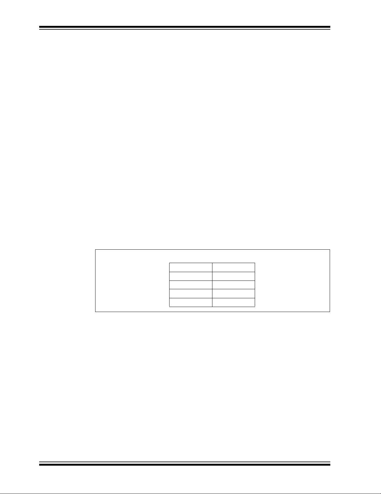
2.2.2.5 SAVE CUSTOMS SETTINGS
If the user chooses Save Custom, all current custom settings will be written and stored
to the on-board EEPROM. These custom settings will be loaded at boot-up for all future
uses. These will remain the boot-up settings until Save Custom is selected again. All
the default settings are listed in Figure 2-6:
FIGURE 2-6: ALL DEFAULT SETTINGS
DS41581A-page 22 2011 Microchip Technology Inc.
Page 23

XLP 8-BIT DEVELOPMENT BOARD
USER’S GUIDE
Chapter 3. XLP 8-Bit Development Board Hardware
3.1 INTRODUCTION
This chapter provides a more detailed description of the hardware features of the XLP
8-Bit Development Board.
3.2 HARDWARE FEATURES
The key features of the XLP 8-bit board are listed below. They are represented in the
order given in Section 1.4 “Development Board Features” and Figure 1-1.
3.2.1 64 and 80 PIC MCU Support
The XLP 8-bit board has been designed to accommodate PIC16 and PIC18 microcontrollers through a Plug-In Module (PIM) containing the microcontroller. A wide variety
of 64 and 80-pin microcontroller devices are available on Plug-In Modules through
Microchip. It is recommended to check all PIM breakout schematics to the XLP schematics to compare for functionality and feature set.
3.2.1.1 FEATURES AVAILABILITY BY PIC16 AND PIC18 DEVICE FAMILY
The high degree of pin compatibility between PIC16 and PIC18 MCU devices allows
both device families to be used with the XLP 8-bit board. However, there are minor differences in pin functionality when migrating from a 64-pin device to a 80-pin device
requiring reconfiguration of the board and some features of the board are not available
for 64-pin devices.
3.2.2 PIC16 and PIC18 Oscillator Options
The installed microcontroller has two separate oscillator circuits connected. An external
oscillator of 10 MHz crystal (Y1) is supplied on board but is not used in the demonstration program. The MCU uses the internal system oscillator in the demonstration program. A second oscillator, using a 32.768 kHz crystal (Y2), functions as the Timer1
oscillator and serves as the source for the RTCC and secondary oscillator.
3.2.3 Power Options
There are (4) methods by which the 8-bit XLP board can be powered.
• USB Cable – Bus power via the USB connector (J11). This provides a nominal 5V
power source, regulated to approximately 3.3V for the microcontroller and board
components, through a Schottky diode and Low Dropout (LDO) regulator circuit
(U2). The green power LED (D5) is illuminated when this power source is used
and bus power is present.
Note: There is no USB data connectivity.
• External Power – An external, regulated DC power supply connected to the V
SRC and one of the GND test points. Voltage is supplied to the board and microcontroller without voltage drops or voltage regulation; therefore, supply voltage
must meet the voltage requirements for the installed PIC16 or PIC18 device. The
power LED does not illuminate in this configuration.
2011 Microchip Technology Inc. DS41581A-page 23
DD
Page 24

XLP 8-Bit Development Board User’s Guide
• Battery Powered – The user has two options available for using external batteries.
- Populating jumper J9 allows the user the option of selecting either two AAA
batteries or a 3V coin battery.
- Populating jumper J12 allows the user to choose one of the following options:
a) one 3V coin battery by populating jumper pins [1-2]
b) two AAA batteries by populating pins [2-3].
The power LED does not illuminate in this configuration.
• Harvester – The user also has an option to use any of Microchip’s Energy
Harvester devices. The supplied demonstration DOES NOT support the use of a
Harvester. The power LED does not illuminate in this configuration.
Note: An example program which utilizes the Energy Harvester with the 8-bit XLP
Development Board is supplied with the 8-bit XLP Software package.
The included PIC16(L)F1947 operates between 1.8V and 3.6V. The included
PIC18F87K22 operates between 1.8V and 5.5V, however for our demonstration program the regulator is disabled, and so the device operates between 1.8V and 3.6V.
Refer to the appropriate device data sheet for other devices.
A four-way jumper block, POWER SOURCE SELECT (J8, J9, J10, J11), selects the
power supply options. See Ta b le 3 - 1 for layout.
TABLE 3-1: POWER JUMPERS
3.2.4 Component Select Jumpers
It is possible to enable and disable multiple component features on the 8-bit XLP
Demonstration board by populating/unpopulating specific jumpers on the board. See
Ta bl e 3 -2 for jumper component configuration.
TABLE 3-2: COMPONENT JUMPERS
DS41581A-page 24 2011 Microchip Technology Inc.
Page 25

• J4 – Population of this jumper enables the pull-up resistor for the PIC16(L)F1947
SDA line, RD5, supplied to the Serial Accessory Port (SAP). Dependent upon
hardware switch (SW4).
• J5 – Population of this jumper enables the pull-up resistor for the PIC18F87K22
SDA line, RD1, supplied to the Serial Accessory Port (SAP). Dependent upon
hardware switch (SW4).
• J15 – Population of this jumper disables the ability to take current measurements
from the MCU. It is recommended to connect measurement equipment to the
PWR ANALYZER header pins [1 – SRC, 2 – GND], by doing this it is easy to
enable/disable current measurement of the MCU.
• J16 – Population of this jumper disables the ability to take current measurements
from the board. It is recommended to connect measurement equipment to the
PWR ANALYZER header pins [7 – SRC, 6 – GND], by doing this it is easy to
enable/disable current measurement of the board.
• J19 – Population of this jumper enables the use of the POT, R9. If left unpopulated, POT will be disabled.
• J20 – Populating this jumper on pins [1-2] will enable ADC readings from the POT.
Populating this jumper on pins [2-3] will enable ADC reading from the on board
MCP9700 temperature sensor. Leaving this jumper unpopulated will disable the
temperature reading feature.
• J23 – Populating this jumper will enable readings for the PICtail™ IRQ from INT2
(RB2). RB2 is not used in the demonstration program, it is recommended to leave
this jumper populated.
• J24 – Populating this jumper will enable readings for the PICtail IRQ from INT1
(RB1). RB1 is used in the demonstration program for the SELECT (RB1) button.
Populating this jumper will prevent the on-board button switch from working correctly. SELECT (RB1) is used to wake from Sleep and basic functionality of the
demonstration program. DO NOT populate this jumper if using the demonstration
program.
• J25 – Populating this jumper will enable readings for the PICtail IRQ from INT0
(RB0). RB0 is used in the demonstration program for the DOWN (RB0) button.
Populating this jumper will prevent the on-board button switch from working correctly. DOWN (RB0) is used for basic functionality of the demonstration program.
DO NOT populate this jumper if using the demonstration program.
• J27 – Populating this jumper will enable the LEDs. The LEDs are not used in the
demonstration program.
3.2.5 SAP SDA Select Switch
There is an on-board hardware switch (SW4) included to allow multiple PIC MCU architecture functionality on the board. The switch allows the user to choose if a PIC16 or
PIC18 device is being used. By toggling the switch, the user is selecting which pin
sends SDA signal to the on-board SAP. It is important to note that even with the switch
toggled, jumpers J4 or J5 are still required to be populated, depending upon which
device is being used.
3.2.6 User-Defined Switches
Three push buttons switches (SW1/MCLR, SW2, SW3) are provided for user-defined
digital inputs. They are connected to the I/O pins, M
pressed, they pull the respective port pin to ground. Using these switches requires that
the corresponding pins internal weak pull-ups be enabled. When the switches are not
required, the pull-ups can be disabled; this adds the ability to reduce power consumption in software.
2011 Microchip Technology Inc. DS41581A-page 25
CLR/RG5, RB1 and RB0. When
Page 26

XLP 8-Bit Development Board User’s Guide
3.2.7 User-Defined LEDs
The board features seven green LEDs [D8 – D1] (RA5, RB5, RB4, RE7, RE6, RE5 and
RE4) that can serve as user-defined outputs. The LEDs are not used in the demonstration software and, by default, jumper J27 is unpopulated, preventing the LEDs use.
3.2.8 Potentiometer
A 100 kΩ potentiometer (R9) is connected to AN3 for both MCU devices. It can be
adjusted from V
The potentiometer functions to show the full capable range of the temperature display.
Its functionality is dependent upon J19 and J20 configuration.
3.2.9 16x2 Character LCD with Controller and Backlight
The board includes the NHD‐C0216CZ‐FSW‐FBW‐3V3 from Newhaven Display International. The screen features the ability to write 2 lines x 16 characters, runs at 3 V
with a 3V backlight display supported by two side White LEDs used for backlight.
3.2.10 Serial EEPROM
A 24AA256 256 KB (32 Kbytes x 8) serial EEPROM (U1) is connected to SPI for both
the PIC16(L)F1947 64-pin and PIC18F87K22 80-pin devices. It is used to demonstrate
SPI bus operation. It is included for nonvolatile firmware storage, in addition to the internal data EEPROM of the PIC16 and PIC18 devices.
DD to VSS to provide an analog input voltage to the A/D Converter.
DD
3.2.11 Modular Expansion Connector
The XLP 8-bit board implements a 28-pin modular expansion interface (J21).
This modular expansion is in place to allow use with some PICtail™ interface available
on many Microchip demo and development boards. It may not implement the full range
of signals supported by some PICtail interfaces; the connector pin assignments for J21
are shown in Appendix 1. “Development Board Schematics”. It is recommended
users reference the schematic before using a PICtail™ expansion on the board. This
additional modular expansion allows the user to incorporate other Microchip demo
boards or all expansion of peripheral features through use of the expansion interface.
3.2.12 Serial Accessory Port
The XLP 8-bit board supports the expansion and use of a serial connection. The SAP
supports the outputs of (TX, V
Through the use of SW4 and J4/J5 the user has the ability to output a signal which can
be recognized through UART, SAP, or I
upon the SAP PROTOCOL switch (S1).
DD, GND, SDA, SCL, RX) from the SAP header (J2).
2
C™. The type of communication is dependent
3.2.13 Temperature Sensor
The MCP9700 Low-Power Linear Active Thermistor IC supports a range of -40°C to
+125°C and operates between the range of 2.3V and 5.5V, consuming typically 6 uA
current when active. The temperature sensor’s output is read by the MCU through pin
RA3 if jumper J20 is set to pins [2-3].
3.2.14 Generous Prototyping Area
To assist in the development and testing of application hardware, the XLP board
includes a 24 x 11 prototype area for the installation of the user’s custom circuitry.
Sources for the board power V
from 19 different I/O signals, the prototyping area supplies a wide range of possible features which can be tested and experimented with from the prototyping area.
DS41581A-page 26 2011 Microchip Technology Inc.
DD and ground are located above the area. Supplied
Page 27

3.2.15 Programming Interfaces
The PICkit header (J3) can be used by either the PICkit™ 2 or PICkit™ 3 programming
devices. Through use of the PICkit 3 the user is capable of debugging the included
demonstration software or creating and debugging custom software in use with the
8-bit XLP.
3.3 CURRENT MEASUREMENT
An advantage to the XLP 8-bit board is its provisions for in-circuit current measurement.
Using simple techniques and equipment, users can experiment directly with low-power
hardware and software techniques, then directly measure their current consumption
without introducing measurement induced artifacts. This provides a fast method of
directly validating power-saving strategies. To make measurements more useful, the
development board allows for the measurement of microcontroller current draw and
non-microcontroller component current separately.
3.3.1 PIC16LF1947 and PIC18F87K22 Current Measurement
To measure current consumed by the PIC microcontrollers, the VMCU jumper (J15)
can be removed and a current measurement cable connected to its pins. This allows
the user to empirically evaluate the microcontroller’s various low-power features. Since
J15 interrupts the microcontroller’s V
when measurements are not being taken. To avoid starving the microcontroller’s current supply and causing low-power conditions, it may be necessary to switch the
ammeter to a higher current range during programming and full-power operation. When
the microcontroller is operating in a low-power state, switching to a low range will produce a more accurate measurement.
DD path, always be certain to re-install the jumper
3.3.2 Development Board Power Measurement
The VBOARD jumper (J16) allows the user to measure the current consumed by the
various board components. It also permits the user to experiment with low-power techniques on a variety of commonly used components. Current measurements taken at
J16 exclude current consumption from the microcontroller, ICSP™ header and the
USB interface. Therefore, communications with a host PC and emulator/programmer
connections do not need to be accounted for in determining an accurate current measurement, as they are not included in the first place. Since J16 interrupts the V
DD path
to the board’s other components, always be certain to re-install the jumper when measurements are not being taken.
3.3.3 Ammeter Tool Header
The XLP 8-bit board includes a special 7-pin header (J14) for current measurement.
The PIC MCU VMCU and VBOARD jumpers (J15 and J16) ensure continuity of power
when connecting or disconnecting a current measurement device. Microchip provides
an optional XLP Current Measurement Cable (part number AC002023) as a convenient
way of connecting the header to an ammeter.
Note: Since the resistor is placed in series with the PIC MCU V
ing voltage drop may affect power calculations. Ensure calculations are
based on actual V
DD, instead of the supplied board voltage.
DD pin, the result-
2011 Microchip Technology Inc. DS41581A-page 27
Page 28

XLP 8-Bit Development Board User’s Guide
NOTES:
DS41581A-page 28 2011 Microchip Technology Inc.
Page 29

XLP 8-BIT DEVELOPMENT BOARD
USER’S GUIDE
Appendix 1. Development Board Schematics
The following schematic diagrams are included in this appendix:
• Figure 1-1: PIC16LF1947 PIM Breakout
• Figure 1-2: PIC18F87K22 PIM Breakout
• Figure 1-3: Schematic for XLP Development Board (1 of 2)
• Figure 1-4: Schematic for XLP Development Board (2 of 2)
2011 Microchip Technology Inc. DS41581A-page 29
Page 30

XLP 8-Bit Development Board User’s Guide
FIGURE 1-1: PIC16LF1947 PIM BREAKOUT
DS41581A-page 30 2011 Microchip Technology Inc.
Page 31

FIGURE 1-2: PIC18F87K22 PIM BREAKOUT
2011 Microchip Technology Inc. DS41581A-page 31
Page 32

XLP 8-Bit Development Board User’s Guide
FIGURE 1-3: SCHEMATIC FOR XLP DEVELOPMENT BOARD (1 OF 2)
DS41581A-page 32 2011 Microchip Technology Inc.
Page 33

FIGURE 1-4: SCHEMATIC FOR XLP DEVELOPMENT BOARD (2 OF 2)
2011 Microchip Technology Inc. DS41581A-page 33
Page 34

XLP 8-Bit Development Board User’s Guide
NOTES:
DS41581A-page 34 2011 Microchip Technology Inc.
Page 35

XLP 8-BIT DEVELOPMENT BOARD
USER’S GUIDE
Index
Numerics
2x16 Character LCD ................................................ 12
32 kHz LFINTOSC ................................................... 21
4 MHz HFINTOSC ................................................... 21
500 kHz MFINTOSC................................................ 21
8-Bit XLP Main Menu............................................... 18
A
Active Display .......................................................... 19
B
Brown-out Reset (BOR)........................................... 20
Buttons Layout ......................................................... 18
C
Connector for Plug-In Modules (PIM)....................... 12
Conserve Mode........................................................ 19
Customer Notification Service.................................... 8
Customer Support...................................................... 9
D
Documentation
Conventions........................................................ 6
Layout ................................................................. 5
F
Frequency Settings.................................................. 21
G
Generous Prototyping Area ..................................... 26
I
I/O Based Interrupts................................................. 20
IC Power Select Jumpers......................................... 12
Internet Address......................................................... 8
J
Jumper Table ........................................................... 16
L
LCD Settings............................................................ 22
LDO Regulator ......................................................... 12
M
MCLR Button ........................................................... 18
Microchip Internet Web Site....................................... 8
Microcontroller Master Clear Switch ........................ 12
Modular 28-Pin Riser Interface ................................ 12
O
Oscillator Circuits (10 MHz and 32.768 kHz)........... 12
Oscillator Options..................................................... 23
P
PIC16 and PIC18 Oscillator Options........................ 23
PIC16(L)F1947......................................................... 11
PIC16(L)F1947 Plug-In Module ............................... 12
PIC16(L)F-series...................................................... 11
PIC18 K-series ......................................................... 11
PIC18F87K22..................................................... 11
PIC18F87K22 Plug-In Module ................................. 12
PICkit™ Programmer/Debugger 6-Pin Interface...... 12
Plug-In Modules (PIMs)............................................ 11
Potentiometer................................................11
Power Analyzer Cable.............................................. 12
Power LED ............................................................... 12
Power Options.......................................................... 23
Power Source Select................................................ 24
Programming Interfaces........................................... 27
Prototyping Area ...................................................... 11
Push Buttons............................................................ 12
, 15
, 12, 26
R
Reading, Recommended ........................................... 7
Readme...................................................................... 7
Real Time Clock Counter (RTCC)............................ 18
Revision History ......................................................... 9
RTCC ....................................................................... 20
S
SAP I²C pull-ups....................................................... 15
SAP PROTOCOL Switch ......................................... 26
SAP SDA Select Switch ........................................... 25
Save Customs Settings............................................ 22
Secondary Oscillator SOSC..................................... 20
Serial Accessory Port......................................... 11
Serial Accessory Port (SAP) .................................... 11
Serial EEPROM ................................................. 12
Serial EEPROM Storage.......................................... 11
, 12
, 26
T
Temperature Sensor .....................................11, 12, 26
Temperature Settings............................................... 21
Timer1 ...................................................................... 19
U
ULPWU .................................................................... 20
USB Cable ............................................................... 15
USB mini-B Cable .................................................... 12
USBPWR ................................................................. 15
User-Defined LEDs .................................................. 26
User-Defined Switches............................................. 25
V
VBOARD .................................................................. 15
VBOARD Jumper (J16)............................................ 27
2011 Microchip Technology Inc. DS41581A-page 35
Page 36

XLP 8-Bit Development Board User’s Guide
W
Warranty Registration................................................. 7
Watchdog Timer (WDT) ........................................... 20
WWW Address...........................................................8
DS41581A-page 36 2011 Microchip Technology Inc.
Page 37

NOTES:
XLP 8-Bit Development Board User’s Guide
2011 Microchip Technology Inc. DS41581A-page 37
Page 38

Worldwide Sales and Service
AMERICAS
Corporate Office
2355 West Chandler Blvd.
Chandler, AZ 85224-6199
Tel: 480-792-7200
Fax: 480-792-7277
Technical Support:
http://www.microchip.com/
support
Web Address:
www.microchip.com
Atlanta
Duluth, GA
Tel: 678-957-9614
Fax: 678-957-1455
Boston
Westborough, MA
Tel: 774-760-0087
Fax: 774-760-0088
Chicago
Itasca, IL
Tel: 630-285-0071
Fax: 630-285-0075
Cleveland
Independence, OH
Tel: 216-447-0464
Fax: 216-447-0643
Dallas
Addison, TX
Tel: 972-818-7423
Fax: 972-818-2924
Detroit
Farmington Hills, MI
Tel: 248-538-2250
Fax: 248-538-2260
Indianapolis
Noblesville, IN
Tel: 317-773-8323
Fax: 317-773-5453
Los Angeles
Mission Viejo, CA
Tel: 949-462-9523
Fax: 949-462-9608
Santa Clara
Santa Clara, CA
Tel: 408-961-6444
Fax: 408-961-6445
Toronto
Mississauga, Ontario,
Canada
Tel: 905-673-0699
Fax: 905-673-6509
ASIA/PACIFIC
Asia Pacific Office
Suites 3707-14, 37th Floor
Tower 6, The Gateway
Harbour City, Kowloon
Hong Kong
Tel: 852-2401-1200
Fax: 852-2401-3431
Australia - Sydney
Tel: 61-2-9868-6733
Fax: 61-2-9868-6755
China - Beijing
Tel: 86-10-8569-7000
Fax: 86-10-8528-2104
China - Chengdu
Tel: 86-28-8665-5511
Fax: 86-28-8665-7889
China - Chongqing
Tel: 86-23-8980-9588
Fax: 86-23-8980-9500
China - Hangzhou
Tel: 86-571-2819-3180
Fax: 86-571-2819-3189
China - Hong Kong SAR
Tel: 852-2401-1200
Fax: 852-2401-3431
China - Nanjing
Tel: 86-25-8473-2460
Fax: 86-25-8473-2470
China - Qingdao
Tel: 86-532-8502-7355
Fax: 86-532-8502-7205
China - Shanghai
Tel: 86-21-5407-5533
Fax: 86-21-5407-5066
China - Shenyang
Tel: 86-24-2334-2829
Fax: 86-24-2334-2393
China - Shenzhen
Tel: 86-755-8203-2660
Fax: 86-755-8203-1760
China - Wuhan
Tel: 86-27-5980-5300
Fax: 86-27-5980-5118
China - Xian
Tel: 86-29-8833-7252
Fax: 86-29-8833-7256
China - Xiamen
Tel: 86-592-2388138
Fax: 86-592-2388130
China - Zhuhai
Tel: 86-756-3210040
Fax: 86-756-3210049
ASIA/PACIFIC
India - Bangalore
Tel: 91-80-3090-4444
Fax: 91-80-3090-4123
India - New Delhi
Tel: 91-11-4160-8631
Fax: 91-11-4160-8632
India - Pune
Tel: 91-20-2566-1512
Fax: 91-20-2566-1513
Japan - Yokohama
Tel: 81-45-471- 6166
Fax: 81-45-471-6122
Korea - Daegu
Tel: 82-53-744-4301
Fax: 82-53-744-4302
Korea - Seoul
Tel: 82-2-554-7200
Fax: 82-2-558-5932 or
82-2-558-5934
Malaysia - Kuala Lumpur
Tel: 60-3-6201-9857
Fax: 60-3-6201-9859
Malaysia - Penang
Tel: 60-4-227-8870
Fax: 60-4-227-4068
Philippines - Manila
Tel: 63-2-634-9065
Fax: 63-2-634-9069
Singapore
Tel: 65-6334-8870
Fax: 65-6334-8850
Tai wan - Hsin Chu
Tel: 886-3-6578-300
Fax: 886-3-6578-370
Taiwan - Kaohsiung
Tel: 886-7-213-7830
Fax: 886-7-330-9305
Taiwan - Taipei
Tel: 886-2-2500-6610
Fax: 886-2-2508-0102
Thailand - Bangkok
Tel: 66-2-694-1351
Fax: 66-2-694-1350
EUROPE
Austria - Wels
Tel: 43-7242-2244-39
Fax: 43-7242-2244-393
Denmark - Copenhagen
Tel: 45-4450-2828
Fax: 45-4485-2829
France - Paris
Tel: 33-1-69-53-63-20
Fax: 33-1-69-30-90-79
Germany - Munich
Tel: 49-89-627-144-0
Fax: 49-89-627-144-44
Italy - Milan
Tel: 39-0331-742611
Fax: 39-0331-466781
Netherlands - Drunen
Tel: 31-416-690399
Fax: 31-416-690340
Spain - Madrid
Tel: 34-91-708-08-90
Fax: 34-91-708-08-91
UK - Wokingham
Tel: 44-118-921-5869
Fax: 44-118-921-5820
05/02/11
DS41581A-page 38 2011 Microchip Technology Inc.
Page 39

Mouser Electronics
Authorized Distributor
Click to View Pricing, Inventory, Delivery & Lifecycle Information:
Microchip:
DM240313
 Loading...