

Page 1
TC815
3-1/2 Digit Auto-Ranging A/D Converter with
Triplex LCD Drive and Display Hold Function
Features
• Auto-Range Operation for AC and DC Voltage
and Resistance Measurements
- TwoUser Selected AC/DC Current Ranges
20mA and 200mA
• 22 Operating Ranges
- 9 D C/AC Voltage
- 4 AC/DC Current
- 9 R esistance and Low Power Ohms
• Display HOLD Function
• 3-1/2 Digit Resolution in Auto-Range Mode:
- 1/2000
• Extended Resolution in Manual Mode: 1/3000
• Memory Mode for Relative Measurements:
-±5%F.S.
• Internal AC to DC Conversion Op Amp
• Triplex LCD Drive for Decimal Points, Digits
and Annunciators
• Continuity Detection and Piezoelectric
Transducer Driver
• CompactSurface Mounted 64-pin
Plastic Flat Package
• Low Drift Internal Reference: 75ppm/°C
• 9V Battery Operation: 10mW
• Low Battery Detection and LCD Annunciator
Device Selection Table
Part Num ber Package
TC815CBU 64-PinPQFP 0°Cto+70°C
Operating
Temperature Range
General Description
The TC815 is a 3-1/2 digit integrating analog-to-digital
converter with triplex LCD display drive and automatic
ranging. A display hold function is on-chip. Input voltage/ohm attenuators ranging from 1 to 1/10,000 are
automatically selected. Five full scale ranges are provided. The CMOS TC815 contains all the logic and
analog switches needed to manufacture an autoranging instrument for ohms and voltage measurements.Userselected20mA and 200mA current ranges
are available. Full scale range and decimal point LCD
annunciators are automatically set in auto-range operation. Auto-range operation is available during ohms
(high and low power ohms) and voltage ( AC and DC)
measurements, eliminating expensive range switches
in hand-held DMM designs. The auto-range feature
may be bypassed allowing decimal point selection and
input attenuator selection control through a single line
input. Expensive r otary switches are not required.
During Manual mode operation, resolution is extended
to 3000 counts full scale. The extended range operation is indicated by a flashing 1 MSD. The extended
resolution is also available during 200kΩ and 2000V
full scale auto-range operation.
The Memory mode subtracts a reading, up to ±5% of
full scale from subsequent measurements. Typical
applicationsinvolve probe resistancecompensationfor
resistance measurements, tolerance measurements,
and tare weight measurements.
The TC815 includes an AC to DC converter for
AC measurements. Only external diodes/resistors/
capacitors are required.
A complete LCD annunciator set describes the TC815
meter function and measurement range during ohms,
voltage and current operation. AC measurements are
indicatedaswellasauto-rangeoperation.A low battery
detection circuit also sets the l ow battery display
annunciator. The triplex LCD display dr ive levels may
be set and temperature compensation applied via the
V
pin. With HOLD low, the display is not updated.
DISP
A HOLD mode LCD annunciator is activated.
The “low ohms” measurement option allows in-circuit
resistance measurements by preventing semiconductor junctions from being forward biased.
2002 Microchip TechnologyInc. DS21474B-page 1
Page 2
TC815
A continuity buzzer output i s activated with inputs less
than 1% of full scale. An overrange input signal also
enablesthe buzzer,exceptduringresistance measurements, and flashes the MSD display.
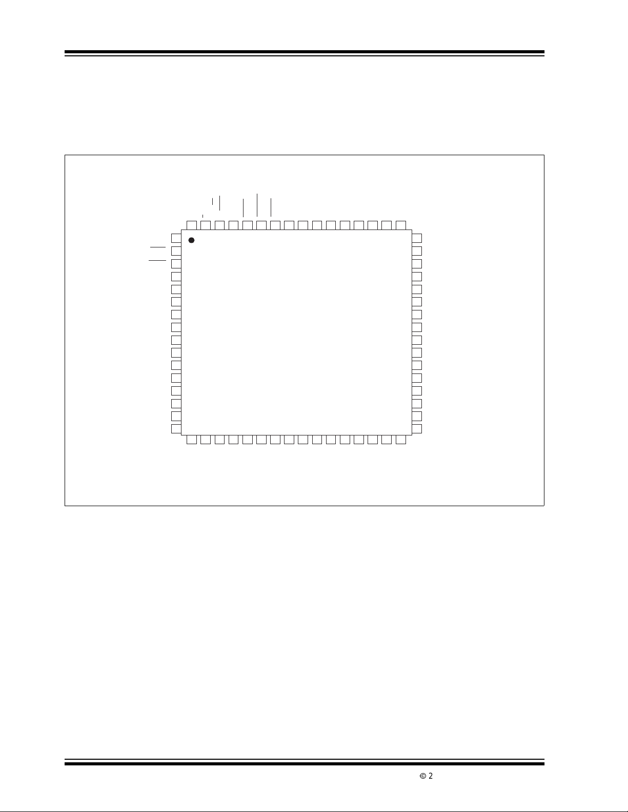
Package Type
64-Pin PQFP
RANGE
-MEM
NC
OHM
20mA
BUZ
XTAL1
XTAL2
V
DISP
BP1
BP2
BP3
LOΩ/A
Ω/V
k/m/
HOLD
BCP0
AGD0
FE0
I
NC
DC/AC
1
2
3
4
5
6
7
8
9
10
11
12
13
14
15
16
NC
BCP1
Ω/LOWΩ
61
AGD1
FE1
HOLD
BCP2
TC815
AGD2
DGND
24 25 26 27 28 29 3018 19 20 21 22 23 3217
FE2
SSA
ACVH
V
BCP3
AC/–/AUTO
Featuring single 9V battery operation, 10mW power
consumption, a precision internal voltage reference
(75ppm/°C max TC) and a compact surface mounted
64-pin quad flat package, the TC815 is ideal for portable instruments.
X
AZ
R
CFI
AD1
AD0
RΩBUF
RVIBUF
CC
SSD
V
V
-MEM/BATT
52 51 50 4964 63 62 58 57 56 55 54 5360 59
ANALOG COM
31
REFH
RM
REFL
RM
C
REFL
C
NC
48
47
C
I
46
ACVL
45
I
I
V
44
I
43
VR4
42
VR5
41
VR2
40
VR3
39
ΩR5
38
ΩR4
37
ΩR3
36
ΩR2
35
ΩR1
34
REFHI
33
C
REFH
DS21474B-page 2
2002 Microchip TechnologyInc.
Page 3
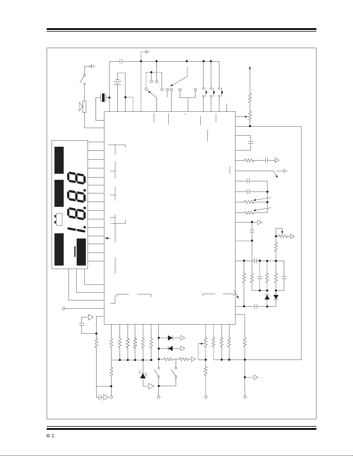
Typical Application and Test Circuit
TC815
Tri-Plex
LCD Display
HOLD LO
– +
-MEM
kΩ
AC
mVA
EnableAudio
AUTO
32.768kHz
( 33kHz)
6
Transducer
54
XTAL1BUZ
BCP3 BCP2FE2 AGD2 BCP1FE1 AGD1 BCP0FE0 AGD0
26 24 23 22 21 20 19 18 16 15 14
-MEM/
V K/m
Ω
/A
1150 7 8 9 10 12 13 25
Ω
39pf
9V
+ –
57
28
CC
SSA
V
V
XTAL2
1's10's100's
Segment & Decimal Point Drive
1000's
BATT
AC/–/AUTO
HOLD
Display
Annunciators
27
V
SSD
V
58
Digital GND
SIA
Ω
SIB
20mA
3
20mA
V
Ω
200mA
2
OHMS
20mA
63
I
200mA
TC815
with HOLD Function
3-1/2 Digit Auto-Ranging DMM
30
61
59
62
REFH
-MEM
RM
ANALOG
DC/AC or Ω/LOWΩ
Manual RANGE Change
REFHI
COM
REFH
C
REFL
INT HOLD CIF C
AZ
BUF RVIBUF C
Ω
ADI ACVH ACVL R
CC
To V
153.850mV
R19/5kΩ R18/24kΩ
REF
C
0.1µF
R20
100
kΩ
INT
0.1µF0.1µF
C
AZ
C
150
kΩ
200
kΩ
C1/1µF
C2/0.22µF
C6
0.01µF
RΩBUF RVIBUF
R26/3kΩ
R27/2kΩ
C4/µf
– +
R23/10kΩ
R22/470kΩ
R21/2.2MΩ
Drivers
Backplane
Ohms Range Attenuator
LCD Bias
0.1µF
Peak Drive Signal ≈ 5V.
If LCD Bias is Connected to DIG GND,
2002 Microchip TechnologyInc. DS21474B-page 3
RX VDISP BP1 BP2 BP3 LO
RMREFL
ΩR5 (÷ 10,000)
ΩR4 (÷ 1,000)
ΩR3 (÷ 100)
38
31
39
R6/100kΩ
R7/100kΩ
0.01
R8/220Ω (PTC)
µF
R5/1.6385MΩ
Ohms
Input
Positive
36
R2/1638.5Ω
R4/163.85kΩ37R3/16.385kΩ
Z1
Resistor
Coefficient
Temperature
ΩR2 (÷ 10)
R1 (÷ 1)
35
R1/163.85
6.2V
I
I
45
20mA
Input
Current
D3 D4
R15
9Ω
1Ω
R16
200mA
(÷1)
I
V
444140
R13
500kΩ
R14/9.9MΩ
Input
Voltage
(÷10)
R2
V
R12/1.11MΩ
ADO
Voltage Range Attenuator
42 53 52 56 46 54 55 49 47 60 51 32 33 29 34
(÷100)
(÷1,000)
(÷10,000)
R3
R4
R5
V
V
V
43
R10/10kΩ
R11/101kΩ
4.7µf
R9/1kΩ
Common
D2
– +
C5/1µf
R24/10kΩ
D1
*Not Required when Resistor Network is used.
Page 4

TC815
1.0 ELECTRICAL
CHARACTERISTICS
Absolute Maximum Ratings*
Supply Voltage (V+ to V–) .....................................15V
Analog Input Voltage (Either Input) ................V+ to V-
*Stresses above those listed under "Absolute Maximum
Ratings" may cause permanent damage to the device. These
are stress ratings only and functional operation of the device
at these or any other conditions above those indicated in the
operation sections of the specifications is not implied.
Exposure to Absolute Maximum Rating conditions f or
extended periods may affectdevice reliability.
Reference Input Voltage.................................. V+ to V-
Voltage at Pin 45 ........................................GND ±0.7V
Power Dissipation (T
≤ 70°C)
A
64-Pin Plastic Flat Package ...........................1.14W
Operating Temperature Range:
Commercial Package (C) ....................0°C to +70°C
StorageTemperature Range..............-65°C to +150°C
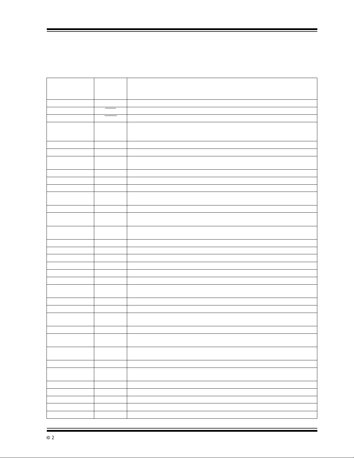
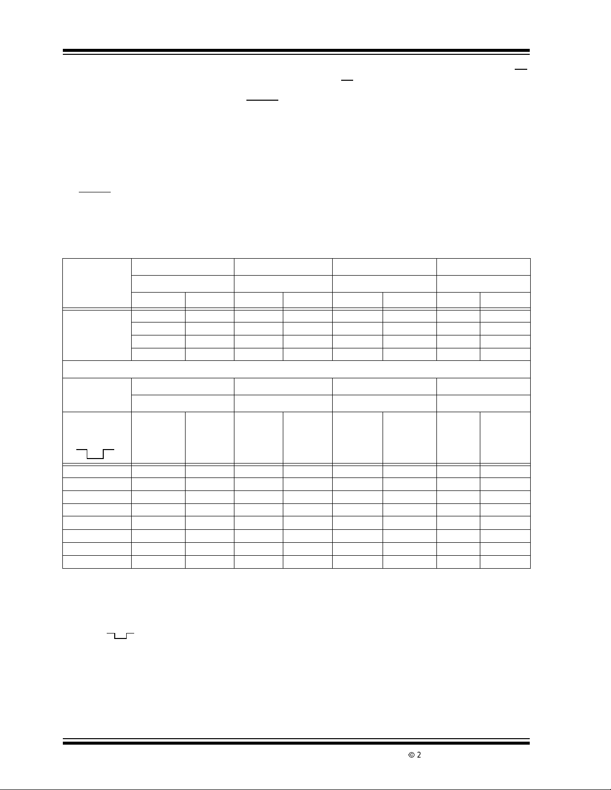
TC815 ELECTRICAL SPECIFICATIONS
Electrical Characteristics: VA=9V,TA= +25°C, unless otherwise specified(see TypicalApplication and Test CircuitFigure).
Symbol Parameter Min Typ Max Unit Test Conditions
Zero Input Reading Input Resistor -0000 0000 +0000 Digital Reading 200mV Range w/o 10MΩ Input
-0001 — +0001 Digital Reading 200mV Range w/10MΩ Input
-0000 0000 +0000 Digital Reading 20mA and 200mA Range
RE RolloverError — — ±1 Count 200mV Rangew/o 10MΩ
— — ±3 200mV Rangew/10MΩ Input
— — ±1 20mA and 200mA Range
NL Linearity Error — — ±1 Count Best Case Straight Line
I
E
V
V
V
IN
N
COM
CTC
IL
Input Leakage Current — — 10 pA
Input Noise — 20 — µV
AC Frequency Error — ±1 — % 40Hz to 500Hz
— ±5 — % 40Hz to 200Hz
Open Circuit Voltage — 570 660 mV Excludes 200Ω Range
Open Circuit Voltage — 285 350 mV Excludes 200Ω Range
Analog Common Voltage 2.5 2.6 3.3 V (V+-V
CommonVoltage Temperature
Coefficient
Display Multiplex Rate — 100 — Hz
Low Logic Input — — 1 V 20mA,AC,I,LOWΩ,HOLD
Logic 1 Pull-up Current — 25 — µA20mA
Buzzer Drive Frequency — 4 — kHz
Low Battery Flag Voltage 6.3 6.6 7.0 V V
Operating Supply Current — 0.8 1.5 mA
— — 50 ppm/°C
p-p
Input Resistor
BW = 0.1 to 10Hz
for OHM Measurements
for LO OHM Measurement
)
COM
Range, -MEM, OHMs
(Relative to DGND Pin 58)
,AC,I,LOWΩ,HOLD
Range, -MEM, OHMs
(Relative to DGND Pin 58)
to V
CC
SSA
DS21474B-page 4
2002 Microchip TechnologyInc.
Page 5
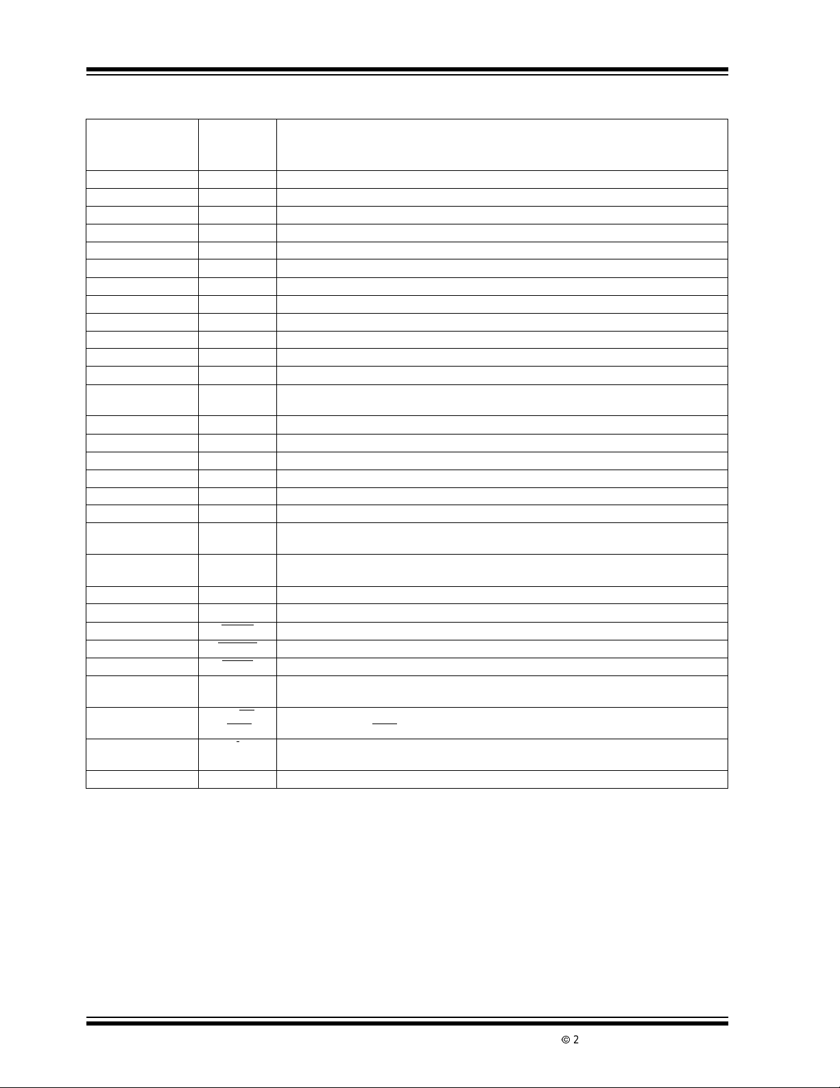
2.0 PIN DESCRIPTIONS
ThedescriptionsofthepinsarelistedinTable2-1.
TABLE 2-1: PIN FUNCTION TABLE
Pin Number
(64-Pin Plastic)
Quad Flat Package
1 NC Logic Input. “0” (Digital Ground) for resistance measurement.
2OHM
320mA
4 BUZ Audio frequency, 4kHz, output for continuity indication during resistance measurement. A
5 XTAL1 32.768kHz Crystal Connection.
6 XTAL2 32.768kHz Crystal Connection.
7V
8 BP1 LCD Backplane#1.
9 BP2 LCD Backplane#2.
10 BP3 LCD Backplane #3.
11 LOΩ/A LCD Annunciator segment drive for low ohms resistancemeasurement and current
12 Ω/V LCD Annunciator segmentdriveforresistancemeasurement and voltagemeasurement.
13 k/m/HOLD LCD Annunciator segmentdrivefork (“kilo-ohms”), m (“milliamps” and
14 BCP0
15 ADG0 LCD segment drive for “a,” “g,” “d” segmentsof LSD.
16 FE0 LCD segment drive for “f” and “e” segments of LSD.
17 NC Noconnection.
18 BCP1 LCD segmentdrivefor“b,” “c” segments and decimal point of 2nd LSD.
19 AGD1 LCD segment drive for “a,” “g,” “d” segmentsof 2nd LSD (Ten’s digit).
20 FE1 LCD segment drive for “f” and “e” segments of 2nd LSD.
21 BCP2 LCD segmentdrivefor“b,” “c” segments and decimal point of 3rd LSD
22 AGD2 LCD segment drive for “a,” “g,” “d” segmentsof 3rd LSD.
23 FE2 LCD segment drive for “b,” “c” segments and decimalpointof3rd LSD.
24 BCP3 LCD segmentdrivefor“b,” “c” segments and decimal point of MSD
25 AC/-/AUTO LCD annunciator drive signal for AC measurements, polarity, and auto-range operation.
26 -MEM/BATT LCD annunciator drive signal for low battery indication and Memory
27 V
28 V
29 ANALOG
30 RM
31 RM
32 C
33 C
34 REFHI Reference voltage for voltageandcurrentmeasurement;nominally 163.85mV.
Symbol Description
Logic Input. “0” (Digital Ground) for 20mA full scale current measurement.
Audio frequency, 4kHz, output for continuity indication during resistance measurement.
non-continuous 4kHz signal is output to indicate an input overrange during voltageor
current measurements.
DISP
(One’s digit)
SSD
CC
COM
REFH
REFL
REFL
REFH
Setspeak LCD drive signal: VP-VDD-V
temperature variation of LCD crystal threshold voltage.
measurement.
“millivolts”) and HOLD mode.
LCD segment drive for “b,” “c” segments and decimal point of least significant digit (LSD).
(Hundred’sdigit).
(Thousand’sdigit).
(Relative Measurement) mode.
Negative battery supplyconnection for internaldigital circuits. Connect to negativeterminal
of battery.
Positive battery supply connection.
Analogcircuit ground reference point. Nominally 2.6V below V
Ratiometric (Resistance measurement) referencehigh voltage.
Ratiometric (Resistance measurement) reference low voltage.
Reference capacitor negative terminal C
Reference capacitor positive terminal C
DISP.VDISP
0.1µf.
REF
0.1µf.
REF
TC815
mayalsobeusedtocompensatefor
.
CC
2002 Microchip TechnologyInc. DS21474B-page 5
Page 6
TC815
TABLE 2-1: PIN FUNCTION TABLE (CONT INUED)
Pin Number
(64-Pin Plastic)
Quad Flat Package
35 ΩR1 Standard resistorconnection for 200Ω full scale.
36 ΩR2 Standard resistorconnection for 2000Ω full scale.
37 ΩR3 Standard resistorconnection for 20kΩ full scale range.
38 ΩR4 Standard resistorconnection for 200kΩ full scale range.
39 ΩR5 Standard resistor connection for 2000kΩ full scale range.
40 VR3 Voltage measurement ÷ 100 attenuator.
41 VR2 Voltage measurement ÷ 10 attenuator.
42 VR5 Voltage measurement ÷ 10,000attenuator.
43 VR4 Voltage measurement ÷ 1000 attenuator.
44 V
45 I
46 ACVL Low output of AC to DC converter.
47 C
48 NC No connection.
49 C
50 R
51 CFI Input filter connection.
52 AD1 Negative input of internal AC to DC operational amplifier.
53 AD0 Output of internal AC to DC operational amplifier.
54 RΩBUF Activebuffer output for resistance measurement.Integration resistor connection. Integrator
55 RVIBUF Active buffer output for voltage and current measurement. Integration resistorconnection.
56 ACVH Positive output of AC to DC converter.
57 V
58 DGND
59 RANGE
60 HOLD
61 -MEM Input to enter Memory Measurement mode for relative measurements. The two LSD’s are
62 DS/AC
63 I
64 NC No connection.
Symbol Description
Unknown voltage input ÷ 1 attenuator.
I
I
AZ
X
SSA
Ω/LOWΩ
Unknown current input.
Integratorcapacitor connection. Nominally 0.1µf. (Lowdielectric absorption.Polypropylene
I
dielectrics suggested.)
Auto-zero capacitor connection; nominally 0.1µf.
Unknown resistanceinput.
resistor nominally220kΩ.
Integration resistor nominally 150kΩ.
Negative supply connection for analog circuits. Connect to negative terminal of 9V battery.
Internal logic digital ground. The logic “0” level.Nominally 4.7V belowVCC.
Input to set manual operation and change ranges.
Inputto hold display. Connect to DIG GND.
stored and subtracted from future measurements.
Input that selects AC or DC option during voltage/current measurements. For resistance
measurements, Ω/LOWΩ, the ohms or low power (voltage) ohms option can be selected.
Inputto selectcurrent measurement. Set to logic “0” (Digitalground) for
current measurement
DS21474B-page 6
2002 Microchip TechnologyInc.
Page 7
TC815
3.0 DETAILED DESCRIPTION
3.1 Resistance, Voltage, Current
Measurement Selection
The TC815 is designed to measure voltage, current,
and resistance.Auto-rangingisavailableforresistance
and voltage measurements. The OHMS
I
(Pin63) input controls are normally pulled internally to
V
By tying these pins to Digital Ground (Pin 58), the
CC.
TC815 is configured internally to measure resistance,
voltage, or current. The required signal combinations
are shown in Table 3-1.
TABLE 3-1: MEASUREMENT SELECTION
LOGIC
Function Select Pin
OHM (Pin 2) I
0 0 Voltage
0 1 Resistance
1 0 Current
1 1 Voltage
Note 1: 0=DigitalGround
2: 1 = Floating or Tied to V
3: OHM and I are normally pulled internally high to
V
(Pin 28). This is considered a logic “1.”
CC
4: Logic “0” is the potentialat digital ground (Pin 58).
(Pin 63)
CC
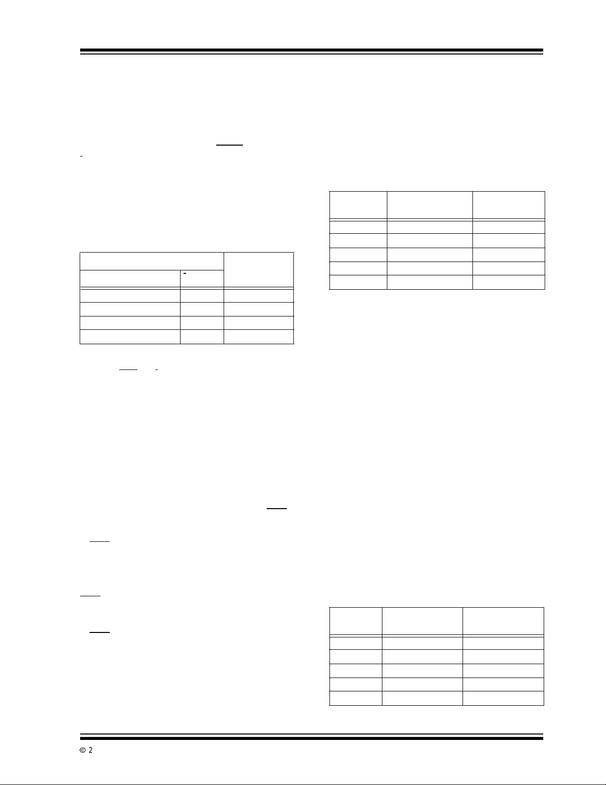
3.2 Resistance Measurements
(Ohms and Low Power O hm s)
The TC815 can be configured to reliably measure incircuit resistances shunted by semiconductor junctions. The TC815 Low Power Ohms Measurement
mode limits the probe open circuit voltage. This preventssemiconductorjunctionsi n the measured system
from turning on.
In the Resistance Measurement mode, the Ω/LOW
(Pin 62) i nput selects the Low Power Ohms Measurement mode. For low power ohms measurements,
Ω/LOW
Ω (Pin 62) is momentarily brought low to digital
ground potential. The TC815 sets up for a low power
ohms measurement with a maximum open circuit
probe voltage of 0.35V above analog common. In the
Low Power Ohms mode, an LCD display annunciator,
LOW
Ω, will be activated. On power-up, t he Low Power
Ohms mode is not active.
If the Manual mode has been selected, toggling
Ω/LOW
Ω will reset the TC815 back to the Auto-Range
mode. In Manual mode, the decision to make a normal
or low power ohms measurement should be made
before selecting the desired range.
(Pin 2) and
Selected
Measurement
The low power ohms measurement is not available on
the 100Ω f ull scale range. Open circuit voltage on this
range is below 2.8V. The standard resistance values
are listed in Table 3-2.
R8, a positive temperature coefficient resistor, and the
6.2V zener Z1 in Figure 3-1, provide input voltage protection during ohms measurements.
TABLE 3-2: OHMS RANGE LADDER
NETWORK
Full Scale
Range
200Ω 163.85Ω (R1) NO
2000Ω 1638.5 kΩ (R2) YES
20kΩ 16,385Ω (R3) YES
200kΩ 16385Ω (R 4) YES
2,000kΩ 1,638,500Ω (R5) YES
Standard
Resistance
Low Power
Ohms Mode
3.3 Ratiometric Resistance
Measurements
The TC815 measures r esistance ratiometrically. Accuracy is set by theexternalstandard resistors connected
to Pin 35 through 39. A Low Power Ohms mode may
be selected on all but the 200Ω full scale range. The
Low Power Ohms modelimitsthevoltageapplied to the
measured system. This allows accurate “in-circuit”
measurementswhen a resistor is shunted by semiconductorjunctions.Full auto-ranging is provided.External
precisionstandardresistorsareautomaticallyswitched
to provide the proper range.
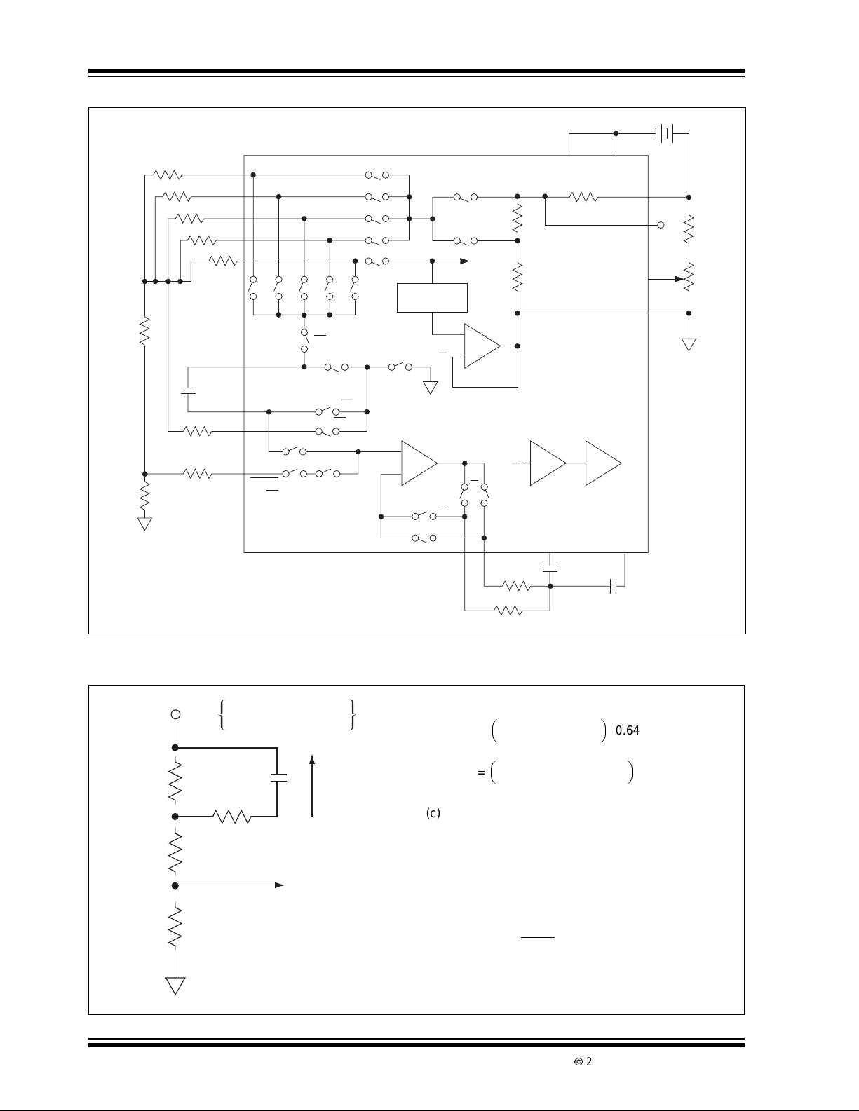
Figure 3-1 shows a detailed block diagram of the
TC815 configured for ratiometric resistance measurements.Duringthesignalintegratephase,thereference
capacitorchargesto a voltage inversely proportionalto
the measured resistance, R
conversion accuracy relies on the accuracy of the
Ω
external standard resistors only.
Normally the required accuracy of the standard resis-
tanceswillbedictatedby the accuracy specificationsof
the users end product. Table 3-3 gives the equivalent
ohms per count for various full scale ranges to allow
users to judge the required resistor f or accuracy.
TABLE 3-3: REFERENCE RESISTORS
Full Scale
Range
200k 163.85 0.1
2k 1638.5 1
20k 16385 10
200k 163850 100
2M 1638500 1000
Reference
Resistor
. Figure 3-2 shows the
X
Ω/Count
2002 Microchip TechnologyInc. DS21474B-page 7
Page 8
TC815
FIGURE 3-1: RATIOMETRIC RESISTANCE MEASUREMENT FUNCTIONAL DIAGRAM
9V
V
SSA
5730
V
CC
28
30
REFHI
34
29
Common
R8
220Ω
R
X
R5/1638500Ω
R4/163850Ω
R3/16385Ω
R2/1638.5Ω
R1/163.85Ω
÷10
÷100
÷1k
÷10k
C
0.1µF
R6/100kΩ
R7/100k
Unknown
÷1
REF
V
SSD
DE
DE S23
•
S29
S30
S31
S32
S33
Ω
•
DE
DE • Ω
~
CC
10kΩ
1.5kV
- 2.6V
Ohms
ΩΩ
•
HI
VA
÷1÷10÷100÷1k÷10k
Voltage
S19DES20
Reference
VCC - 2.8V
≈
DE + Ω
S28S27S26S25S24
~
Low Ohms
• LO
Ω
•
V
+
–
1.5kΩ
CC
V
TC815
Buffer
S35
ΩΩ
Integrator Comparator
S36
S34
S37
Ω
Ω
39
38
37
36
35
33
32
50
31
Ω
50
V •
S18
S21
S12 S13
1
•
INT • (Ω + DC)
1
Analog
R18
24kΩ
5kΩ
RVIBUF
150kΩ
220kΩ
49
C
AZ
0.1µF
C
INT
0.1µF
RΩBUF
5554
FIGURE 3-2: RESISTANCE MEASUREMENT ACCURACY SET BY EXTERNAL
STANDARD RESISTOR
Example: 200kΩ Full Scale Measurement
163.85kΩ
(a )
(b)
V
V
-------------------------------------------------
R
163.85 220 R
++
--------------------------------------------------------------
X
163.85kΩ 220Ω R
R
X
++
x0.64=
X
X
(c) “ Ramp Up Voltage” = “Ramp Down Voltage”
.
..
V
X
---------------- x T
RIC
()
I
=
---------------- T
I
()
V
RIC
X
I
Where:
R
= Integrating Resistor, TI= I ntegrate Time
I
= Integrating Capacitor, T
C
(d) R
I
= 163.85
X
(TDE)
T
I
DE =
Independentof RI,CIor Internal Voltage Ref erence
R
16.385k
Unknown
0.64V for Ohms
VA
0.32V for LO Ohms
+
S
C
REF
100 kΩ
V
R
V
R
220Ω
V
X
R
X
To Analog Buffer
47
x0.64=
DE
Deintegrate Time
DS21474B-page 8
2002 Microchip TechnologyInc.
Page 9

TC815
F
3.4 Voltage Measurement
Resistive dividers are automatically changed to provide
in range readings for 200mV to 2000V full scale readings
(Figure3-3). The input resistance is set by external
resistors R14/R13. The divider leg resistors are R9-R12.
FIGURE 3-3: TC815 ANALOG SECTION
Ohms
Input
Current Input
Common
D1
R24
10k
0.1µF
R7/100kΩ
Ω
R8/220
(PTC)
0.01µF
Voltage
Input
*Not required when
Resistor Network is used.
+
Ω
Z1
6.2V
20mA
200mA
R16/1
R14/9.9MΩ
C3
1µF
R26
33kΩ
R27/2kΩ
R6/100kΩ
R5/1.638MΩ
R4/163.85kΩ
R3/16385Ω
R2/1638.5Ω
R1/163.85Ω
R15/9
Ω
D2
R23
10kΩ
R12/1.11M
R11/101k
R10/10k
RM
Ω
D3
D4
R13/500kΩ*
R9/1k
Ω
4.7µF
+
C4
1µF
ΩR
REFL
ΩR
ΩR
ΩR
ΩR
ΩR
I 45
I
V 44
I
Ω
Ω
Ω
R22
470
W
k
C2
0.22 µF
ACVH
C1/1µF
ACVL 46
V
V
V
V
ADI
X
R2
R3
R4
R2
R21
2.2
M
50
31
39
5
38
4
37
3
36
2
35
1
•
ΩΩ Ω Ω Ω
1/1
V
CC
V•
1/10V•1/100
S6
41
40
43
42
AC-to-DC
Converter
53
Op Amp
ADO
Ω
52
S14
56
Ω
INT• •AC
S40
Ω
INT• •AC
S32S33 S31 S30
•• ••
1/10 1/100
S7
S39
Ω
INT+ +DC
V•
1/1
k
S8 S9
+
–
S15 AZ
1/1k
S10
S1
V•
1/10k
S2
S3
S4
S5
The divider leg resistors give a 200mV signal V
(Pin 44) for full scale voltages from 200mV to 2000V.
For applications which do not require a 10mΩ input
impedance, the divider network impedances may be
lowered. This will reduce voltage offset errors induced
by switch leakage currents.
S29
1/10k
Ω
V•1/1
V•1/10
V•1/100
V•1/1k
V•1/10k
Buffer
+
–
S35 S37
Ω
S34
RBUF
RBUF
S12 V • 1/1
S21 DE •
S24 1/10k•
W
S25
S26
S27
S28
+ 1
S11
S13
Ω
Ω
54
Ω
Ω
Ω
•
Ω
1/1k
Ω
•
1/100
•
Ω
1/10
1/1•
Ω
Ω
+AC
INT•( +DC)
Ω
55
Ω
R
RVI
BUF
BUF
220
Ω
k
150
k
Ω
Ω
TC815
V
CC
10kΩ
ΩΩ
S44 HI
•
+
2.8V
–
Ω
S38 AZ
S43
INT
C
1.5k
WΩ
LO
•
REF AMP
1.5k
+
–
•
DE
S17 DE-
–
+
Comparator
0.01µF0.01µF
INT
V
CC
S22 S22
ΩΩ
DE •
S20 DE
S18 DE
S19 DE+
S16 DE+
–
+
Integrator
49 47
C
AZ
CAZ
30
RM
REFH
R18/24k
R19/5k
29
ANALOG
COM
34
REFHI
163.85mV
≈
33 C
REFH
REFH
32 C
REFL
51 CIF
R20/100kΩ
V
CC
Ω
Ω
C6
To Digital
Section
0.1µFC
0.01µ
I
2002 Microchip TechnologyInc. DS21474B-page 9
Page 10

TC815
3.5 Current Measurement
The TC815 measures current only under manual range
operation. The two user selectable full scale ranges
are: 20mA
ment mode by holding the I
ground potential. The OHM
or tied to the positive supply.
Tworanges ar e possible. The 20mA
selectedby connectingthe 20mA
ground. If left floating the 200mA full scale range is
selected.
External current to voltage conversion resistors are
used at the I
a10Ω resistor is used. The 200mA range needs a 1Ω
resistor; full scale is 200mV.
PC board trace resistance between analog common
and R16 (see Figure 2-1) must be minimized. In the
200mA range, for example, a 0.05 trace resistance will
cause a 5% current to voltage conversion error at I
(Pin 45).
The extended resolutionmeasurementoption operates
during current measurements. To minimize rollover
error the potential difference between ANALOG COM
(Pin 29) and system common must be minimized.
and 200mA. Select the current Measure-
input (Pin 63) low at digital
input (Pin 2) is left floating
full scale range i s
input(Pin 3) to digital
input (Pin 45). For 20mA measurements
I
3.6 Measurement Options
(AC to DC Measurements)
In voltage and current measurements, the TC815 can
be configured for AC measurements. An on-chip operational amplifier and external rectifier components perform the AC to DC conversion.
When power is first applied, the TC815 enters t he DC
Measurementmode.ForACmeasurements(current or
voltage),AC
digitalgroundpotential; the TC815 sets-up for AC measurements and the AC liquid crystal display annunciator activates. Toggling AC
TC815 t o DC operation.
If the Manual Operating mode has been selected, toggling AC
Range mode. In Manual mode operation, AC or DC
operation should be selected first and then the desired
range selected.
I
The minimum AC voltage fullscale voltage range is 2V.
The DC f ull scale minimum voltage is 200mV. AC current measurements are available on the 20mA and
100mA full scale current ranges.
/DC (Pin 62) is momentarilybrought low to
/DC low again will return the
/DC will reset the TC815 back to the Auto-
DS21474B-page 10
2002 Microchip TechnologyInc.
Page 11

TC815
4.0 CONVERSION TIMING
The TC815 analog-to-digital converter uses the conventional dual slope integrating conversion technique
with an added phase that automatically eliminateszero
offset errors. The TC815 gives a zero reading with a
zero volt input.
The TC815 is designed to operate with a 32.768kHz
crystal.The 32kHz crystal is low cost and readily available; it serves as a time-base oscillator crystal in many
digital clocks. (See External Crystal Sources.)
The external clock is divided by two. The internal clock
frequency is 16.348kHz, giving a clock period of
61.04µsec. The total conversion — auto-zero phase,
signal integrate and reference deintegrate — requires
8000 clock periods or 488.3msec. There are approximately two complete conversions per second.
The integration time is fixed at 1638.5 clock periods or
100msec. This gives rejection of 50/60Hz AC line
noise.
The maximum reference de-integrate time, representing a full scale analog input, is 3000 clock periods or
183.1msec during manual extended resolution operation. The 3000 counts are available in Manual mode,
extended resolution operation only. In Auto-Ranging
mode, the maximum de-integrate time is 2000 clock
periods. The 1000 clock periods are added to the autozero phase. An auto-ranging, or manual conversion
takes 8000 clock periods. After a zero crossing is
detectedintheReferenceDe-integratemode,theautozero phase is entered. Figure 4-1 shows the basic
TC815 timing relationships.
FIGURE 4-1: BASIC T C815
CONVERSION TIMING
TC815
Auto-Zero
Phase
Min. Auto-Zero
Time
3361.5T
Signal
Integrate
Phase
P
8000 T
T
CONV
External Crystal = 32.768kHz
Internal ClockPeriod = T
Total Conversion Time= T
=488.3mec≈ 2Conv/Sec.
Integration Time= T
Maximum Reference De-integration Time =
T
=3000(TP) = 183.1msec
DE
(ManualExtended Resolution)
MinimumAuto-Zero Time
= (8000-3000-1638.5) (T
(Manual,Extended Resolution)
= (8000-2000-1638.5) (T
(Auto-Range)
Reference
De-integrate
Phase
Extended
Resolution
Zero Crossing
Fixed
1638.5 TP
*Max
3000.0 T
P
T
DE
Signal
=8000(TP)
*In Auto-Range Operation
Maximum is 2000TP and
Minimum Auto-Zero time
i s 4361.5T
T
I
To Input
P
= 2/32.768 = 61.04µsec
P
CONV
= 1638.5 (TP) = 100.0msec.
I
)=205.1msec
P
)=266.2msec
P
Next Conversion
Auto-Zero Cycle
P
2002 Microchip TechnologyInc. DS21474B-page 11
Page 12
TC815
5.0 MANUAL RANGE SELECTION
The TC815 voltage and resistance auto-ranging feature can be disabled by momentarily bringing RANGE
(Pin 59) to digital ground potential (Pin 58). When the
change from auto-to-manual ranging occurs, the first
manual range selected is the last range in the AutoRanging mode.
The TC815 power-up circuit selects auto-range operation initially. Once the manual range option is entered,
range changes are made by momentarily grounding
the RANGE
Manual Range mode until the measurement function
TABLE 5-1: MANUAL RANGE OPERATION
Power-on
Auto-Range
Operation
Manual Operation
control input. The TC815 remains in the
DC Volts AC Volts Ohm LO Ohm
Input
Input
23.5V 18.2V
Range Display Range Range Display Range Range Display
200mV “1”00.0V 2V “1”000V 200Ω “1”00.0Ω 2kΩ “1”.000kΩ
2V 1.000V 20V 18.20V 2kΩ “1”.000kΩ 10kΩ “1”.0.00kΩ
20V “1”0.00V — — 20kΩ 18.20Ω 200kΩ “1”.00.0kΩ
200V 23.5V — — — — 2000kΩ “1”350kΩ
DC Volts AC Volts Ohm LO Ohm
23.5V 18.2V
(voltage or resistance), or measurement option (AC
DC, Ω/LO
Ω) changes. This causesthe TC815 to return
to auto-ranging operation.
The “ Auto” LCD annunciator driver is active only in t he
Auto-Range mode. Table 5-1 shows typical operation,
where the manual range selection option is used. Also
shown is the extended resolution display format.
Also see Figure 5-1 through Figure 5-3.
18.2kΩ 2.35MΩ
18.2kΩ 2.35MΩ
/
# of Range
Changes
(See Note 4
1 200V 23.5V 20V 18.20V 20kΩ 18.20V 2000kΩ “1”350kΩ
2 200mV “1”00.0V 2V “1”.000V 200Ω “1”00.0ΩkΩ 2kΩ “1”.000kΩ
3 2V 1.000V 20V 18.20V 2kΩ “1”000kΩ 20kΩ “1”0.00kΩ
4 20V “1”3.50V 20V 18.2V 20kΩ 18.20kΩ 200kΩ “1”00.0kΩ
5 200V 23.5V 600V 19V 200kΩ 18.2kΩ 2000kΩ “1”350kΩ
6 1000V 24V 2V “1”.000V 2000kΩ 19kΩ 2kΩ “1”.000kΩ
7 200mV “1”00.0mV 20V 18.20V 200kΩ “1”00.0Ω 20kΩ “1”0.00kΩ
8 2V “1”.000V 200V 18.2V 2kΩ “1”.000kΩ 200kΩ “1”00.0kΩ
Note 1: A flashing MSD is shown as a “1”. A flashing MSD indicates the TC815 is over-ranging if all other digits are zero.
2: The first manual range selected is the last range in the Auto-Rangingmode.
3: A flashing MSD with a non-zerodisplay indicatestheTC815 has enteredtheExtended Resolution Operating mode.An
additional 1000 counts of resolution is available. This extended operation is available only in manual operation for voltage,
resistance and current measurements.
4: = Momentary ground connection.
Range Display Range Range Display Range Range Display
)
DS21474B-page 12
2002 Microchip TechnologyInc.
Page 13

TC815
r
r
FIGURE 5-1: MANUAL RANGE
SELECTION:RESISTANCE
MEASUREMENTS
Manual Range
Select
Continuity
Indicator
Output 4kHz
Audio
Frequency
Continuous 4kHz
Buzzer
Yes
*Mode also operates when Auto-Ranging Operation
is selected and 2MΩ < R
Is
< 19
R
X
?
No
Is
> 3000
R
X
?
No
Is
> 2000
R
X
?
No
Display True
Reading
Yes
"1" = > Flashing MSD
Yes*
< 2.999MΩ
X
TC815
Over Range Indicato
Display "1" 000
Display Last
3 Digits and Flash
MSD
Extended
Resolution
Feature
For resistance measurements, the buzzer signal does
notindicateanoverrangecondition.The buzzerisused
to indicate continuity. Continuity is defined as a resistance reading less than 19 counts.
FIGURE 5-2: MANUAL RANGE
SELECTION: CURRENT
MEASUREMENTS
Range
Select
I
> 3000
X
I
> 2000
X
Yes
Is
Yes
?
No
Is
Yes
?
No
TC815
Output 4kHz
Audio
Frequency
Over Range Indicato
Display
"1" 000
"1" = > Flashing MSD
Display Last
3 Digits and Flash
MSD
Extended
Resolution
Feature
FIGURE 5-3: MANUAL RANGE
SELECTION: VOLTAGE
MEASUREMENTS
Range Select
Is
V
> 3000
X
?
No
Is
> 2000
V
X
?
No
Display True
Reading
Yes
Yes
TC815
Output Noncontinuous
4kHz Audio
Frequency
Over Range Indicator
Display
"1" 000
"1" = > Flashing MSD
Display Last 3 Digits
and Flash
MSD
Extended Resolution
Feature
5.1 E xtended Resolution
Manual Operation
The TC815 extends resolution by 50% when operated
in the Manual Range Select mode for current, voltage,
and resistancemeasurements.Resolutionincreases to
3000 counts from 2000 counts. The extended resolution feature operates only on the 2000kΩ and 2000V
ranges during auto-range operation.
In the Extended Resolution Operating mode, readings
above 1999 are displayed with a blinking “1” most significant digit. The blinking “1” should be interpreted as
the digit 2. The three least significantdigitsdisplaydata
normally.
An input overrange condition causes the most significant digit to blink and sets the three least significant
digitsto display “000.” The buzzer output is enabled for
input voltage and current signals with readings greater
than 2000 counts i n both manual and auto-range
operation.
Display True
Reading
2002 Microchip TechnologyInc. DS21474B-page 13
Page 14

TC815
6.0 -MEM OPERATING MODE
Bringing -MEM (Pin 61) momentarily low configures the
TC815 “-MEM” Operating mode. The -MEM LCD
Annunciator becomes active. In this Operating mode,
subsequent measurements are made relative to the last
two digits (-99) displayed at the time MEM is low. This
represents5% of fullscale. The lasttwosignificant digits
are stored and subtracted from all the following input
conversions. The following examples clarify operation:
EXAMPLE 6-1: IN AUTO-RANGING
R
(N)= 18.21kΩ (20kΩ Range)= > Display 18.21kΩ
I
MEM
R
(N+1) = 19.87kΩ (20kΩ Range)
I
(N+2) = 22.65kΩ (200kΩ Range)
R
I
EXAMPLE 6-2: IN FIXED RANGE
RI(N) = 18.21kΩ = > Display 18.2kΩ
MEM
(N+1) = 36.7Ω
R
I
R
(N+2) = 5.8Ω
I
*Will display minus resistance if following input is
less than offset stored at fixed range.
EXAMPLE 6-3: IN FIXED RANGE
VI(N) = 0.51V = > Display 0.51V
MEM
V
(N+1) = 3.68V
I
V
(N+2) = 0.23V
I
V
(N+3) = -5.21V
I
On power-up, the TC815 “-MEM” mode is not active.
Once the “-MEM” is entered, bringing MEM
it returns the TC815 to normal operation.
The “-MEM”modeisalso cancelledwheneverthe measurement type (resistance, voltage, current AC
Ω/LO
Ω) or range is changed. The LCD -MEM annunci-
ator will be off in normal operation.
In the auto-rangeoperation,if the following input si gnal
cannot be converted on the same range as the stored
value, the “-MEM” mode is cancelled. The LCD annunciator is turned off.
The “-MEM” Operating mode can be very useful in
resistancemeasurementswhen lead length r esistance
would cause measurement errors.
= > Store 0.21k Ω
= > Display 19.87 - 0.21 = 19.66kΩ
= > Display 22.7kΩ and MEM
disappears
(200.0Ω FULL SCALE)
=>Store8.2Ω
= > Di splay 36.7 - 8.2 = 28.5Ω
= > Di splay 5.8 = 2.4Ω*
=>Store0.51V
= > Di splay 3.68 - 0.51 = 3.17V
= > Di splay 0.23 - 0.51 = -0.28V
= > Di splay - 5.21 - 0.51 = -5.72V
low again,
/DC,
7.0 AUTOMATIC RANGE
SELECTION OPERATION
When power is first applied, the TC815 enters the autorange operating state. The Auto-Range mode may be
entered from Manual mode by changing the measurement function (resistance or voltage), or by changing
the measurement option (AD
The automatic voltage range selection begins on the
most sensitive scale first: 200mV for DC or 2.000V for
AC measurements. The voltage range selection flow
chart is given in Figure 7- 1.
Internal input protection diodes t o V
V
(Pin 57) clamp the input voltage. The external
SSA
10MΩ input r esistance (see Figure 7-1, R14 and R13)
limits current safely in an overrange condition.
The voltage range selection is designed to maximize
resolution. For input signals less than 9% of full scale
(count reading <180), the next most sensitive range is
selected.
An over range voltage input condition is flagged whenever the internal count exceeds 2000, by activating the
buzzer output (Pin 4). This 4kHz signal can directly
drive a piezo electric acoustic transducer. An out of
range input signal causes t he 4kHz signal to be on
122msec, off for 122 msec, on for 122msec and off for
610msec (see Figure 11-1).
Duringvoltageauto-rangeoperation, the extended resolution feature operates on the 2000V range only.(See
Extended Resolution Operating mode discussion.)
The r esistance automatic range selection procedure is
shown in Figure 7-2. The 200Ω range is the first range
selected unless the TC815 low ohms resistance measurementoptionisselected.Inlowohmsoperation,the
first full scale range tried is 2kΩ.
The r esistance range selected maximizes sensitivity. If
the conversion results in a reading less than 180, the
next most sensitive f ull scale range is tried.
If the conversion is less than 19 in auto-range operation, a continuous 4kHz signal is output at BUZ (Pin 4).
An over range input does not activate the buzzer.
Out of range input conditions ar e displayed by a blinking most significant digit with the three l east significant
digits set to “000.”
The extended resolution feature operates only on the
2000kΩ and 2000V full scale range during auto-range
operation. A blinking “1” most significant digit is interpreted as the digit 2. The three least significant digits
display data normally.
/DC, Ω/LOΩ).
DD
(Pin 28) and
DS21474B-page 14
2002 Microchip TechnologyInc.
Page 15

FIGURE 7-1: AUTO-RANGE OPE RAT ION: VOLTAGE MEASUREMENT
p
TC815
N = N + 1
N = 0 if DC
N = 1 if AC
Conversion
VX - (1/10N) V
V
No
Kth
VX < 180
?
No
> 2000
X
?
Yes
N = 4
?
Yes
TC815
N = 0: 200.0mV Full Scale Range
N = 1: 2,000V Full Scale Range
N = N
K
Remaining in Range Selected
during the Kth Conversion
IN
Yes
No
N = N – 1
N = 0 if DC
N = 1 if AC
Yes
Display
Voltae (V
)
X
K = K + 1
Display "1" XXX
V
> 3000
X
?
Yes
Display "1" 000
Flash MSD
Start: Power-on, Function or Measurement O
No
Flash MSD
Activate
Buzzer
Over Range
tion Change
2002 Microchip TechnologyInc. DS21474B-page 15
Page 16

TC815
p
FIGURE 7-2: AUTO-RANGE OPERATION: RESISTANCE MEASUREM E NT
Continuity
Indicator
Activate
Buzzer
Continuous
4kHz Signal
N = 1 if LOΩ
Conversion
RX = (1/10N) R
Yes
N = 0 if Ω
Kth
R
< 19
X
?
RX < 180
?
>2000
R
X
?
No
No
Yes
TC815
N = 0: 200.0Ω Full Scale Range
N = 1: 2,000kΩ Full Scale Range
Remaining in Range Selected
during the Kth Conversion
IN
N = N – 1
No
Yes
N = 0 if
Ω
N =1 if LOW
Yes
Display
Resistance
Ω
K = K + 1
N = N + 1
No
N = 4
?
Yes
Display "1" XXX
>3000
R
X
?
Yes
Start: Power-on, Function or Measurement O
No
Flash MSD
Extended Resolution
Over Range
Display "1" 000
Flash MSD
tion Change
DS21474B-page 16
2002 Microchip TechnologyInc.
Page 17

TC815
r
8.0 LOW BATTERY DETECTION
CIRCUIT
The TC815 contains a low battery detector. When the
9V battery supply has been depleted to a 7V nominal
value, the LCD display low battery annunciator is
activated.
The low battery detector is shown in Figure 8-1. The
low battery annunciator remains OFF with the battery
supplygreaterthan0.7V. The annunciatorisONbefore
the supply battery has reached 6.3V.
FIGURE 8-1: LOW BATTERY
DETECTOR
V
CC
R
1
R
2
Low Battery Detector
V
T
R
3
6.2V
V
Z
V
V
SSA
Comparator
+
–
R
7 X = 6.2V
T
≈
R1 + R
TC815
To LCD
Annunciato
Selection
Logic
2
2
9.0 TRIPLEX LIQUID CRYSTAL
DRIVE
The TC815 directly drives a triplexed liquid crystal display (LCD) using 1/3 bias drive (see Figure 9-1). All
data, decimal point, polarity and function annunciator
drive signals are developed by the TC815. A direct
connection to a triplex LCD display is possible without
external dr ive electronics. Standard and custom LCD
displaysarereadilyavailablefrom LCD manufacturers.
The LCDs must be driven with an AC signal having
zero DC component for long display life. The liquid
crystal polarization is a function of the RMS voltage
appearing across the backplane and segment driver.
The peak drive signal applied to the LCD is: V
V
.
DISP
, for example,isset at a potential 3V below VCC,
IfV
DISP
the peak drive signal is:
V
P=VCC –VDISP
=3V
An “OFF” LCD segment has an RMS voltage of Vp/3
across it or 1 volt. An “ON” segment has a 0.63Vp signal across it or 1.92V for V
Since the V
pin is available, the user may adjust
DISP
CC –VDISP
=3V.
the “ON” and “ OFF” LCD levels for various manufacturer’s displays by changing Vp. The l iquid crystal
threshold voltage moves down with temperature.
CC
“OFF”segmentsmaybecomevisibleathighLCDoperating temperatures. A voltage with a -5 to -20mV/°C
temperature coefficient can be applied to V
DISP
to
accommodate the liquid crystal t emperature operating
characteristics, if necessary.
The TC815 internally generates two intermediate LCD
drive potentials (V
(Figure 9-1), between V
and VL) from a resistive divider
H
(Pin 28) and V
CC
DISP
(Pin 7).
The ladder impedance is approximately 150kΩ.This
drive method is commonly known as 1/3 bias. With
V
connected to digital ground VP≈ 5.0V.
DISP
The intermediate levels are needed so that drive signals giving RMS “ON” and “OFF” levels can be generated. Figure 9-2 shows a typical drive signal and the
resulting wave forms for “ON” and “OFF.” RMS voltage
levels across a selected LCD element. Also, see
Figure 9-3 and Table 9-1.
FIGURE 9-1: 1/3 BIAS LCD DRIVE
V
CC
28
To Triplex
Segment Drive
Logic
V
SSA
TC815
V
H
V
L
VP = VCC – V
"OFF" = VP/3 RMS
11
"ON" = VP RMS
3
3
DISP
50k
50k
50k
Set V
DISP
For Proper V
with Resistive
Divider
6
V
DISP
P
9.1 LCD Displays
Although most users will design t heir own custom LCD
display, several manufacturers offer standard displays
for the TC815. Figure 9-3 shows a typical display available from Varitronix.
-
1. Varitronix Ltd.
4/F Liven House, 61-63, King Yip Street
Kwun Tong, Hong Kong
Tel: (852)2389-4317
Part No.: VIM 310-1 Pin Connector
VIM 310-2 Elastomer Connector
USA OFFICE:
VL Electronics/Varitronix
3250 Wilshire Blvd. Suite 1901
Los Angeles, CA 90010
Tel: (213) 738-8700
2. Adamant Kogyo Co., LTD
16-7, Shinden, 1-Chome, Adachi-Ku,
Tokyo, 123, Japan
Tel: Tokyo 919-1171
2002 Microchip TechnologyInc. DS21474B-page 17
Page 18

TC815
P
P
P
P
P
FIGURE 9-2: TRIPLEX LCD DRIVE WAVEFO RMS
Backplanes
123456
a
f
b
g
e
c
d
BCPAGDFE
BP3
BP2
BP1
VP (3V)
BP1
VP
Backplanes
VH
BP2
VP
VH
BP3
Waveforms to Generate
VL
VL
0
0
Backplanes
123456
Segments Applied
VP
VH
a (FE – BP1)
"On"
b (BCP – BP1)
"On"
c (BCP – BP2)
"On"
d (AGD – BP3)
"On"
e (FE – BP2)
"Off"
f (FE – BP1)
"Off"
g (AGD – BP2)
"On"
–VL
–VH
–VP
–VL
–VH
–VP
–VL
–VH
–VP
–VL
–VH
–VP
–VL
–VH
–VP
–VL
–VH
–VP
–VL
–VH
–VP
0
VP
VH
VL
0
VP
VH
VL
0
VP
VH
VL
0
VP
VH
VL
0
VP
VH
VL
VP
VH
VL
0
RMS Voltage
V
V
V
V
V
V
V
11
=V
RMS
33
11
=V
RMS
33
11
=V
RMS
33
11
=V
RMS
33
V
P
=
RMS
3
V
P
=
RMS
3
11
=V
RMS
33
FIGURE 9-3: TYPICAL LCD DISPLAY CONFIGURATION T C815 TRIPLEX
50.8 (+0.3–0.1)
45.0 Viewing Area Min.
Between Pads 2.54 X 17 - 43.18
C
– +
6
L
36
3
10
HOLD LOΩ
3
5.5
1.4
1
a
f
10
e
b
g
c
2.4
d
kΩ
mVA
3
1
19
- MEM
10.0 Max.
18.0 Viewing Area Min.6.24
0.5
AC
AUTO
Max.
18
Dimensions in mm (Not to Scale)
1.271.27
43 2
P4 P3 P2
2.9
3.81
22.86 (+0.3–0.1)
3.81
30.48 (+0.3–0.1)
0.2
0.2
1.1 1.1
DS21474B-page 18
2002 Microchip TechnologyInc.
Page 19

TC815
TABLE 9-1:
PAD BP1 BP2 BP3 PAD COM1 COM2 COM3
1BP1 / /19/ //
2 / BP2 / 20 / / /
3 / / BP3 21 / / /
4/LOΩ A22 / / /
5/WV23///
6HOLD k m24 / / /
7b1c1/25///
8a1g1d126///
9f1e1/27///
10 b2 c2 P2 28 / / /
11 a2 g2 d2 29 / / /
12 f2 e2 / 30 / / /
13 b3 c3 P3 31 / / /
14 a3 g3 d3 32 / / /
15 f3 e3 / 33 / / /
16 b4 c4 P4 34 / / /
17 AC Auto 35 / / /
18 –MEM / 36 / / /
10.0 EXTERNAL CRYSTAL
The TC815 is designed to operate with a 32,768Hz
crystal. This frequency is internally divided by two to
give a 61.04µsec clock period. One conversion takes
8000 clock periods or 488.3 msec ( ≈ 2 conversions/
second). Integration time is 1638.5 clock periods or
100msec.
The 32kHz quartz crystal is r eadily available and inexpensive.The 32kHz crystal is commonly used in digital
clocks and counters.
Several crystal sources exist. A partial listing is:
• Statek Corporation
512 N. Main
Orange, CA 92668
(714) 639-7810
TWX: 910-593-1355
TELEX: 67-8394
• Fox Electronics
5570 Enterprise Parkway
Fort Myers, FL 33905
(941) 693-0099
Contact manufacturer for full specifications.
2002 Microchip TechnologyInc. DS21474B-page 19
Page 20

TC815
11.0 “BUZZER” DRIVE SIGNAL
The buzzer drive signal for over range is shown in
Figure 11-1 The buzzer output is active for any reading
The TC815 BUZ output (Pin 4) will drive a piezoelectric
audio transducer. The signal is activated to indicate an
input overrange condition for current and voltage
measurements, or continuity during resistance
measurements.
During a resistance measurement, a reading less than
19 on any full scale range, causes a continuous 4kHz
signal to be output. This is used as a continuity
indication.
A voltage or current input measurement overrange is
indicated by a noncontinuous 4kHz signal at t he BUZ
output. The LCD display MSD also flashes and the
over 2000 counts in both manual and auto-range operation. The buzzer is activated during an extended resolutionmeasurement. The BUZ signal swingsfromV
(Pin 28) to Digital Ground (Pin 58).The signal is at V
when not active.
The BUZ output is also activated for 15msec whenever
a range change is made in auto-range or manual operation.Changingthetypeofmeasurement(voltage, current, or resistance) or measurement option (AC
Ω/LO
Ω)willalsoactivatethebuzzeroutputfor15msec.
A range change during a current measurement will not
activate the buzzer output.
three least significant digits are set to display zero.
FIGURE 11-1: TC815 WAVEFORM FOR BUZZER OUTPUT
122ms 122ms 122ms 122ms
1 Conversion
610ms
CC
CC
/DC,
122ms
Digital Ground
4kHz Signal
Internal
TC815
Signals
Integrate
De-integrate
Auto-Zero
BUZ
(Pin 4)
Power-up
V
IN
= 250mV
4000 8000 12000
1000 Clock Pulses
100ms
1638.5CP
122ms
2000CP
200mV Range
Over Range
4kHz 4kHz 4kHz
One Cycle of Over Range
Buzzer activated due
to Power-up
Noncontinuous Buzzer Signal Indicates Input Overrange
Change Range Change Range Change Range
Buzzer
2,000V Range
In Range
2,000V Range
In Range
Due to Manual
Range Change
200mV Range
Extended Range
Range
Change
Manual RangeAuto-Ranging
2,000V Range
In Range
Due to
Due to
Range
Change
122ms 122ms122ms
Buzzer activated due to
Previous Conversion Over Range
Change Input
V
IN
4kHz15ms15ms15ms
= 3.2V
3000CP250CP2500CP250CP250CP
2,000V Range
Out of Range
610ms
Buzzer
activated due
to Previous
Over Range
DS21474B-page 20
2002 Microchip TechnologyInc.
Page 21

TC815
Vendors for piezo electric audio transducers are:
Gulton Industries
•
Piezo Products D ivision
212 Durham Avenue
Metuchen, New Jersey 08840
(201) 548-2800
Typical P/Ns: 102-95NS, 101-FB-00
•
Taiyo Yuden (USA) Inc.
Arlington Center
714 West Algonquin Road
Arlington Heights, Illinois 60005
Typical P/Ns: CB27BB, CB20BB, CB355BB
11.1 Display Decimal Point Selection
The TC815 provides a decimalpoint LCD drive signal.
The decimal point position is a function of the selected
full scale range, as shown in Table 11-1.
TABLE 11-1: DECIMA L POINT SELECTION
1*9 *9 *9
Full Scale Range DP3 DP2 DP1
2000V, 2000kΩ OFF OFF OFF
200V, 200.0kΩ OFF OFF ON
20V, 20.00kΩ OFF ON OFF
2V, 2.000kΩ ON OFF OFF
200V, 200.0Ω OFF OFF OFF
200mV, 200.0Ω OFF OFF ON
20mA OFF ON OFF
200mA OFF OFF ON
11.2 AC-to-DC Converter Operational
Amplifier
The TC815 contains an on-chip operational amplifier
that may be connected as a rectifier for AC-to-DC voltage and current measurements. Typical operational
amplifier characteristics are:
•SlewRate:1V/µsec
• Unity-Gain Bandwidth: 0.4MHz
• Open Loop Gain: 44dB
• Output VoltageSwing (Load = 10kΩ) ± 1.5V
(Referencedto Analog Common)
When the AC measurement option is selected, the
input buffer receives an input signal through switch
S14, rather than switch S11. With external circuits, the
AC Operatingmodecanbeusedto performothertypes
of functions within the constraintsof the internal operational amplifier. External circuitsthat perform true RMS
conversion, or a peak hold function are typical
examples.
11.3 Component Selection
11.3.1 INTEGRATION RESISTOR
SELECTION
The TC815 automatically selects one of two external
integration resistors. RVBUF (pin 55) is selected for
voltage and current measurement. RΩBUF (Pin 54) is
selected for resistance measurements.
11.3.2 RVIBUF SELECTION (P IN 55)
In auto-range operation, the TC815 operates with a
200mV maximum full scale potential at V
Resistive dividers at VR2 (Pin 41), VR3 (Pin 40), VR4
(Pin 43), and VR5 (Pin 42) are automatically switched
to maintain the 200V full scale potential.
In Manual mode, the Extended Operating mode is activated,giving a 300mV full scale potentialat V
The integrator output swing should be maximized, but
saturations must be avoided. The integrator will swing
within 0.45V of V
(Pin 28) and 0.5V of VSS(Pin 57)
CC
without saturating. A ±2V swing is suggested. The
value of RVIBUF is easilycalculated,assuminga worst
case extended resolution input signal:
V
= Integrator swing = ±2V
INT
t
= Integration time = 100msec
I
= Integration capacitor = 0.1µF
C
I
V
= Maximum input at VI= 300mV
MAX
EQUATION 11-1:
RVIBUF =
V
MAX(TI
V
INT(CI
)
= 150kΩ
)
11.3.3 RΩBUF SELECTION (PIN 54)
In ratiometric resistance measurements, the signal at
R
(pin 50) is always positive, with respect to analog
X
common. The integrator swings negative.
The worst case integrator swing is for t he 200Ω range
with the manual, extended resolution option.
The i nput voltage, V
(Pin 50) is easily calculated (see
X
Figure 11-2):
V
ANCOM
R
R
R
R
= Potential at Analog Common ≈ 2.7V
= 220Ω
8
= 163.85Ω
I
= 300Ω
X
= Internal switch 33 resistance ≈ 600Ω
S
EQUATION 11-2:
-(V
V
CC
RΩBUF =
(RX+RS+R1+R8)
ANCOM)RX
(Pin 44).
I
(Pin44).
I
=0.63V
2002 Microchip TechnologyInc. DS21474B-page 21
Page 22

TC815
For a 3.1V integrator swing, the value of RΩBUF is
easily calculated:
V
t
I
C
R
V
= Integrator swing = 3.1V
INT
= Integration time = 100msec
= Integration capacitor = 0.1µF
I
=300Ω
XMAX
= 700mV
X MAX
EQUAT ION 11 -3:
RΩBUF =
V
C
XMAX(TI
I(VINT
)
)
= 200kΩ
FIGURE 11-2: RΩ CALCULATION (200Ω
MANUAL OPERATION)
V
= 9V
CC
SW33
R
R
R
≈ 600Ω
S
163.85Ω
1
220Ω
2
11.5 Reference Voltage Adjustment
The TC815 contains a low temperature drift internal
voltage reference. The analog common potential
(Pin 29) is establishedby this reference. Maximum drift
is a low 75ppm/°C. Analog common is designed to be
approximately 2.6V below V
(Pin 28). A resistive
CC
divider (R18/R19, Functional Diagram) sets the TC815
reference input voltage (REFHI, Pin 34) to approximately 163.85mV.
With an input voltage near full scale on the 200mV
range, R19 is adjusted for the proper reading.
11.6 Display Hold Feature
The LCD will not be updated when HOLD (Pin 60) is
connectedtoGND(Pin58).Conversionsare made, but
the display is not updated. A HO LD
ciator is activated when HOLD
mode LCD annun-
is low.
The LCD HOLD annunciator is activated through the
triplex LCD driver signal at Pin 13.
11.7 Flat Package Socket
Sockets suitable for prototype work are available. A
USA source is:
• Nepenthe Distribution
2471 East Bayshore, Suite 520
Palo Alto, CA 94303
(415) 856-9332
TWX: 910-373-2060
“CBQ” Socket, Part No. IC51-064-042
V
X
R
300Ω
3
Analog Common = VCC – 3V
With a low battery voltageof 6.6V, analog common will
be approximately 3.6V above the negative supply terminal. With the integrator swinging down from analog
common toward the negative supply, a 3.1V swing will
set the integrator output to 0.5V above the negative
supply.
11.4 Capacitors - C
The integration capacitor, C
INT,CAZ
, must have low dielec-
INT
and C
REF
tric absorption.A 0.1µF polypropylenecapacitorissuggested. The auto-zero capacitor, C
capacitor, C
, should be selected for low leakage
REF
, and reference
AZ
and dielectric absorption. Polystyrene capacitors are
good choices.
11.8 Resistive Ladder Networks
Resistorattenuatornetworks for voltageandresistance
measurements are available from:
• Caddock Electronics
1717 Chicago Avenue
Riverside, CA 92507
Tel: (714) 788-1700
TWX: 910-332-6108
TABLE 11-2: RESISTIVE L ADDER
NETWORKS
Attenuator
Accuracy
Attenuator T ype
0.1% Voltage 1776-C441
0.25% Voltage 1776-C44
0.25% Resistance T1794-204-1
Caddock
Part Number
DS21474B-page 22
2002 Microchip TechnologyInc.
Page 23

12.0 PACKAGING INFORMATION
)
12.1 Package Marking Information
Package marking data not available at this time.
12.2 Taping Form
Component Taping Orientation for 64-Pin PQFP Devices
User Direction of Feed
TC815
PIN 1
W
Carrier Tape, Number of Components Per Reel and Reel Size
Package Carrier Width (W) Pitch (P) Part Per Full Reel Reel Size
64-Pin PQFP 32 mm 24 mm 250 13 in
Note: Drawing does not represent total number of pins.
12.3 Package Dimensions
64-Pin PQFP
PIN 1
.018 (0.45)
.012 (0.30)
.031 (0.80) TYP.
P
Standard Reel Component Orientation
for TR Suffix Device
.555 (14.10)
.547 (13.90)
.687 (17.45)
.667 (16.95)
.009 (0.23)
.005 (0.13)
7° MAX.
.041 (1.03)
.031 (0.78)
.555 (14.10)
.547 (13.90)
.687 (17.45)
.667 (16.95)
2002 Microchip TechnologyInc. DS21474B-page 23
.130 (3.30) MAX.
Dimensions: mm (inches
.010 (0.25) TYP.
.120 (3.05)
.100 (2.55)
Page 24

TC815
SALES AND SUPPORT
Data Sheets
Products supportedby a preliminary DataSheetmayhave an erratasheetdescribing minor operational differences and recommendedworkarounds.To determine if an errata sheetexists for a particular device, please contact one of the following:
1. Your local Microchip sales office
2. The Microchip CorporateLiteratureCenter U.S. FAX: (480)792-7277
3. The Microchip Worldwide Site (www.microchip.com)
Pleasespecify which device, revision of silicon and Data Sheet (includeLiterature#) you are using.
New Customer Notification System
Register on our web site (www.microchip.com/cn)toreceive the most currentinformation on our products.
DS21474B-page 24
2002 Microchip TechnologyInc.
Page 25

TC815
Information contained in this publication regarding device
applications and the like is intended through suggestion only
and may be superseded by updates. It is your responsibility to
ensure that your application meets with your specifications.
No representation or warranty is given and no liability is
assumed by Microchip Technology Incorporated with respect
to the accuracy or use of such information, or infringement of
patents or other intellectual property rights arising from such
use or otherwise. Use of Microchip’s products as critical components in life support systems is not authorized except with
express written approval by Microchip. No licenses are conveyed, implicitly or otherwise, under any intellectual property
rights.
Trademarks
The Microchip name and logo, the Microchip logo, FilterLab,
K
EELOQ,microID,MPLAB,PIC,PICmicro,PICMASTER,
PICSTART, PRO MATE, SEEVAL and The Embedded Control
SolutionsCompany areregiste red trademarksof MicrochipTechnologyIncorp or ated in the U.S.A. and other countries .
dsPIC, ECONOMONI TOR, FanSense, FlexROM, fuz zyLAB,
In-Circuit Serial Programming, ICSP, ICEPIC, microPort,
Migratable Memory, MPA SM, MPLIB, MPLINK, MPSIM,
MXDEV, PI CC, PICDEM, PICDE M.net, rfPIC, Select M ode
and Total Enduranceare trademarksof Microchip Technology
Incorporated in the U.S.A.
Serialized Quick Turn Programming (SQTP) is a service mark
of Microchip TechnologyIncorporated in t he U.S.A.
All other trademarks mentioned herein are property of their
respective companies.
© 2002, Microchip Technology Incorporated, Printed in the
U.S.A., All Rights Reserved.
Printed on recycled paper.
Microchip received QS-9000 quality system
certification for its worldwide headquarters,
design and wafer fabrication facilities in
Chandler and Tempe, Arizona in July 1999
and Mountain View, California in March 2002.
The Company’s quality system processes and
procedures are QS-9000 compliant for its
®
PICmicro
devices, Serial EEPROMs, microperipherals,
non-volatile memory and analog products. In
addition, Microchip’s quality system for the
design and manufacture of development
systemsisISO 9001certified.
2002 Microchip TechnologyInc. DS21474B-page 25
8-bit MCUs, KEELOQ®code hopping
Page 26

WORLDWIDE SALES AND SERVICE
AMERICAS
Corporate Office
2355 West Chandler Blvd.
Chandler, AZ 85224-6199
Tel: 480-792-7200 Fax: 480-792-7277
Technical Support: 480-792-7627
Web Address: http://www.microchip.com
Rocky Mountain
2355 West Chandler Blvd.
Chandler, AZ 85224-6199
Tel: 480-792-7966 Fax: 480-792-7456
Atlanta
500 Sugar Mill Road, Suite 200B
Atlanta, GA 30350
Tel: 770-640-0034 Fax: 770-640-0307
Boston
2 Lan Drive, Suite 120
Westford, MA 01886
Tel: 978-692-3848 Fax: 978-692-3821
Chicago
333 Pierce Road, Suite 180
Itasca, IL 60143
Tel: 630-285-0071 Fax: 630-285-0075
Dallas
4570 Westgrove Drive, Suite 160
Addison, TX 75001
Tel: 972-818-7423 Fax: 972-818-2924
Detroit
Tri-Atria Office Building
32255 Northwestern Highway, Suite 190
Farmington Hills, MI 48334
Tel: 248-538-2250 Fax: 248-538-2260
Kokomo
2767 S. Albright Road
Kokomo, Indiana 46902
Tel: 765-864-8360 Fax: 765-864-8387
Los Angeles
18201 Von Karman, Suite 1090
Irvine, CA 92612
Tel: 949-263-1888 Fax: 949-263-1338
New York
150 Motor Parkway, Suite 202
Hauppauge, NY 11788
Tel: 631-273-5305 Fax: 631-273-5335
San Jose
Microchip Technology Inc.
2107 North First Street, Suite 590
San Jose, CA 95131
Tel: 408-436-7950 Fax: 408-436-7955
Toronto
6285 Northam Drive, Suite 108
Mississauga, Ontario L4V 1X5, Canada
Tel: 905-673-0699 Fax: 905-673-6509
ASIA/PACIFIC
Australia
Microchip Technology Australia Pty Ltd
Suite 22, 41 Rawson Street
Epping 2121, NSW
Australia
Tel: 61-2-9868-6733 Fax: 61-2-9868-6755
China - Beijing
Microchip Technology Consulting (Shanghai)
Co., Ltd., Beijing Liaison Office
Unit 915
Bei Hai Wan Tai Bldg.
No. 6 Chaoyangmen Beidajie
Beijing, 100027, No. China
Tel: 86-10-85282100 Fax: 86-10-85282104
China - Chengdu
Microchip Technology Consulting (Shanghai)
Co., Ltd., Chengdu Liaison Office
Rm. 2401, 24th Floor,
Ming Xing Financial Tower
No. 88 TIDU Street
Chengdu 610016, China
Tel: 86-28-6766200 Fax: 86-28-6766599
China - Fuzhou
Microchip Technology Consulting (Shanghai)
Co., Ltd., Fuzhou Liaison Office
Unit 28F, World Trade Plaza
No. 71 Wusi Road
Fuzhou 350001, China
Tel: 86-591-7503506 Fax: 86-591-7503521
China - Shanghai
Microchip Technology Consulting (Shanghai)
Co., Ltd.
Room 701, Bldg. B
Far East International Plaza
No. 317 Xian Xia Road
Shanghai, 200051
Tel: 86-21-6275-5700 Fax: 86-21-6275-5060
China - Shenzhen
Microchip Technology Consulting (Shanghai)
Co., Ltd., Shenzhen Liaison Office
Rm. 1315, 13/F , Shenzhen Kerry Centre,
Renminnan Lu
Shenzhen 518001, China
Tel: 86-755-2350361 Fax: 86-755-2366086
Hong Kong
Microchip Technology Hongkong Ltd.
Unit 901-6, Tower2, Metroplaza
223 Hing Fong Road
Kwai Fong, N.T., Hong Kong
Tel: 852-2401-1200 Fax: 852-2401-3431
India
Microchip Technology Inc.
India Liaison Office
Divyasree Chambers
1 Floor, Wing A (A3/A4)
No. 11, O’Shaugnessey Road
Bangalore, 560 025, India
Tel: 91-80-2290061 Fax: 91-80-2290062
Japan
Microchip Technology Japan K.K.
Benex S-1 6F
3-18-20, Shinyokohama
Kohoku-Ku, Yokohama-shi
Kanagawa, 222-0033, Japan
Tel: 81-45-471- 6166 Fax: 81-45-471-6122
Korea
Microchip Technology Korea
168-1, Youngbo Bldg. 3 Floor
Samsung-Dong, Kangnam-Ku
Seoul, Korea 135-882
Tel: 82-2-554-7200 Fax: 82-2-558-5934
Singapore
Microchip Technology Singapore Pte Ltd.
200 Middle Road
#07-02 Prime Centre
Singapore, 188980
Tel: 65-6334-8870 Fax: 65-6334-8850
Taiwan
Microchip Technology Taiwan
11F-3, No. 207
Tung HuaNorth Road
Taipei, 105, Taiwan
Tel: 886-2-2717-7175 Fax: 886-2-2545-0139
EUROPE
Denmark
Microchip Technology Nordic ApS
Regus Business Centre
Lautrup hoj 1-3
Ballerup DK-2750 Denmark
Tel: 45 4420 9895 Fax: 45 4420 9910
France
Microchip Technology SARL
Parc d’Activite du Moulin de Massy
43 Rue du Saule Trapu
Batiment A - ler Etage
91300 Massy, France
Tel: 33-1-69-53-63-20 Fax: 33-1-69-30-90-79
Germany
Microchip Technology GmbH
Gustav-Heinemann Ring 125
D-81739 Munich, Germany
Tel: 49-89-627-144 0 Fax: 49-89-627-144-44
Italy
Microchip Technology SRL
Centro Direzionale Colleoni
Palazzo Taurus 1 V. Le Colleoni 1
20041 Agrate Brianza
Milan, Italy
Tel: 39-039-65791-1 Fax: 39-039-6899883
United Kingdom
Arizona Microchip Technology Ltd.
505 Eskdale Road
Winnersh Triangle
Wokingham
Berkshire, England RG415TU
Tel: 44 118 921 5869 Fax: 44-118 921-5820
03/01/02
DS21474B-page 26
*DS21474B*
2002 Microchip Technology Inc.
 Loading...