

Page 1

STK600 Starter Kit
STK600 AVR® Flash MCU Starter Kit User's Guide
Overview
The STK600 is a complete starter kit and development system for the AVR® Flash microcontroller. It allows designers
a quick start in developing code on the AVR device, combined with advanced features for using the starter kit to
prototype and test new designs.
New firmware releases for STK600 are embedded with the releases of Atmel Studio. The upgrade process starts with
a connection to the STK600 board (the user will be asked to perform the procedure). Should the automatic upgrade
fail, try the manual upgrade procedure.
© 2019 Microchip Technology Inc.
User Guide
40001904D-page 1
Page 2

STK600 Starter Kit
Table of Contents
Overview........................................................................................................................................................ 1
1. Features.................................................................................................................................................. 4
2. Known Issues..........................................................................................................................................5
3. Device Support........................................................................................................................................6
4. Getting Started...................................................................................................................................... 40
4.1. Kit Contents................................................................................................................................40
4.2. Quick Start..................................................................................................................................40
4.3. Connecting the Hardware...........................................................................................................41
5. Target Socket System........................................................................................................................... 42
5.1. Socket System........................................................................................................................... 42
5.2. Socket Card and Routing Card.................................................................................................. 42
5.3. Selecting the Correct Routing and Socket Cards.......................................................................44
5.4. Mounting the Cards.................................................................................................................... 44
5.5. Signal Integrity............................................................................................................................50
5.6. AVR UC3 Routing Card Pin Mapping.........................................................................................50
5.7. SAM Routing Cards....................................................................................................................78
6. Hardware Description............................................................................................................................79
6.1. STK600 Block Diagram.............................................................................................................. 79
6.2. Target Voltage VTG....................................................................................................................79
6.3. Analog Reference Voltages........................................................................................................80
6.4. RESET Control...........................................................................................................................82
6.5. Port Connectors......................................................................................................................... 83
6.6. LEDs and Switches.................................................................................................................... 84
6.7. Clock Settings............................................................................................................................ 85
6.8. User RS-232 Interface................................................................................................................87
6.9. DataFlash Nonvolatile Memory.................................................................................................. 88
6.10. Expansion Connectors............................................................................................................... 89
6.11. User USB Connector..................................................................................................................92
6.12. CAN Transceiver........................................................................................................................ 93
6.13. LIN Transceiver.......................................................................................................................... 95
6.14. Miscellaneous.............................................................................................................................96
7. Programming.........................................................................................................................................97
7.1. ISP Programming....................................................................................................................... 97
7.2. Parallel High-Voltage Programming........................................................................................... 98
7.3. Serial High-Voltage Programming..............................................................................................99
7.4. JTAG Programming..................................................................................................................101
7.5. PDI Programming.....................................................................................................................102
7.6. UPDI Programming.................................................................................................................. 103
7.7. aWire Programming................................................................................................................. 105
7.8. TPI Programming..................................................................................................................... 106
7.9. In-System Programming of an External Target System........................................................... 108
© 2019 Microchip Technology Inc.
User Guide
40001904D-page 2
Page 3

STK600 Starter Kit
8. Command-Line Utility.......................................................................................................................... 111
9. Troubleshooting and Support.............................................................................................................. 112
9.1. Troubleshooting Guide............................................................................................................. 112
9.2. Routing and Socket Card Issues.............................................................................................. 115
9.3. Technical Support..................................................................................................................... 115
9.4. Firmware Upgrade....................................................................................................................115
10. Revision History...................................................................................................................................117
The Microchip Website............................................................................................................................... 118
Product Change Notification Service..........................................................................................................118
Customer Support...................................................................................................................................... 118
Microchip Devices Code Protection Feature.............................................................................................. 118
Legal Notice................................................................................................................................................118
Trademarks.................................................................................................................................................119
Quality Management System..................................................................................................................... 119
Worldwide Sales and Service.....................................................................................................................120
© 2019 Microchip Technology Inc.
User Guide
40001904D-page 3
Page 4

1. Features
• AVR® Studio 4/AVR32 Studio/AVR Studio 5/Atmel Studio Compatible
• USB Interface to PC for Programming and Control
• Powered from the USB Bus or an External 10-15V DC Power Supply
• Adjustable Target VCC (0-5.5V)
• Two Adjustable Reference Voltages with High Accuracy (0-5.0V, 10 mV res.)
• Clock Oscillator, Adjustable On-The-Fly from Atmel Studio (0-50 MHz, 0.1% res.)
• Serial In-System Programming (ISP) of tinyAVR and megaAVR® Devices
• PDI Programming of AVR XMEGA® Devices
• JTAG Programming of megaAVR, AVR XMEGA, and AVR UC3 Devices
• aWire Programming of AVR UC3 Devices
• ISP and JTAG Programming of AVR Devices in External Target Systems
• Flexible Routing and Socket Card System for Easy Mounting of all Supported Devices
• Eight Push Buttons for General Use
• Eight LEDs for General Use
• All AVR I/O Ports are Easily Accessible through Pin Header Connectors
• Expansion Connectors for Plug-In Modules and Prototyping Area
• On-Board 4 Mb DataFlash for Nonvolatile Data
• USB mini-AB (On-The-Go) Connector for AVR Devices with USB
• PHY and DSUB-9 Connector for RS-232 Interface
• PHY and DSUB-9 Connector for CAN Bus
• PHY and Header for LIN Bus
• Device Board with an ATmega2560 AVR Microcontroller Included
Note: Socket cards and routing cards must be bought separately.
STK600 Starter Kit
Features
© 2019 Microchip Technology Inc.
User Guide
40001904D-page 4
Page 5

2. Known Issues
There are no known issues with the STK600.
STK600 Starter Kit
Known Issues
© 2019 Microchip Technology Inc.
User Guide
40001904D-page 5
Page 6

3. Device Support
Atmel Studio, AVR Studio 4, 5, and AVR32 Studio has support for a range of devices in all speed grades. Support for
new AVR devices may be added in new versions of the software. Latest versions of the Integrated Development
Environments are always available from www.microchip.com.
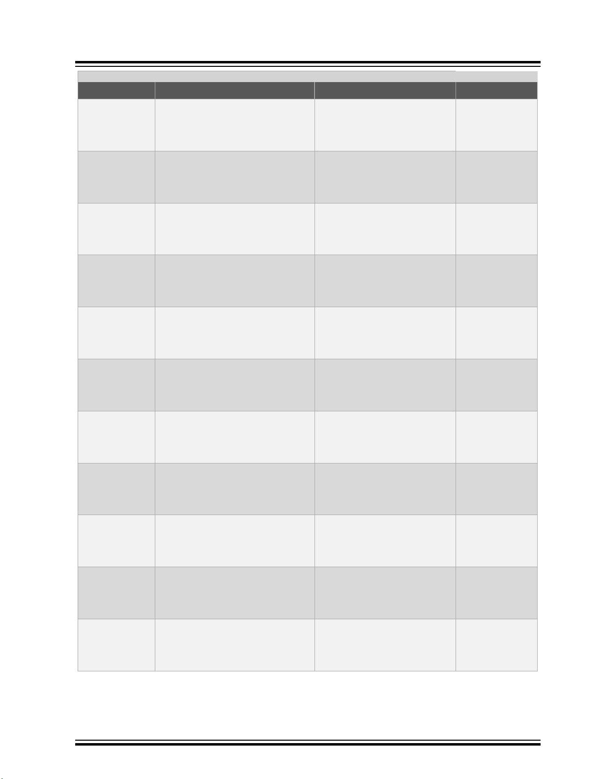
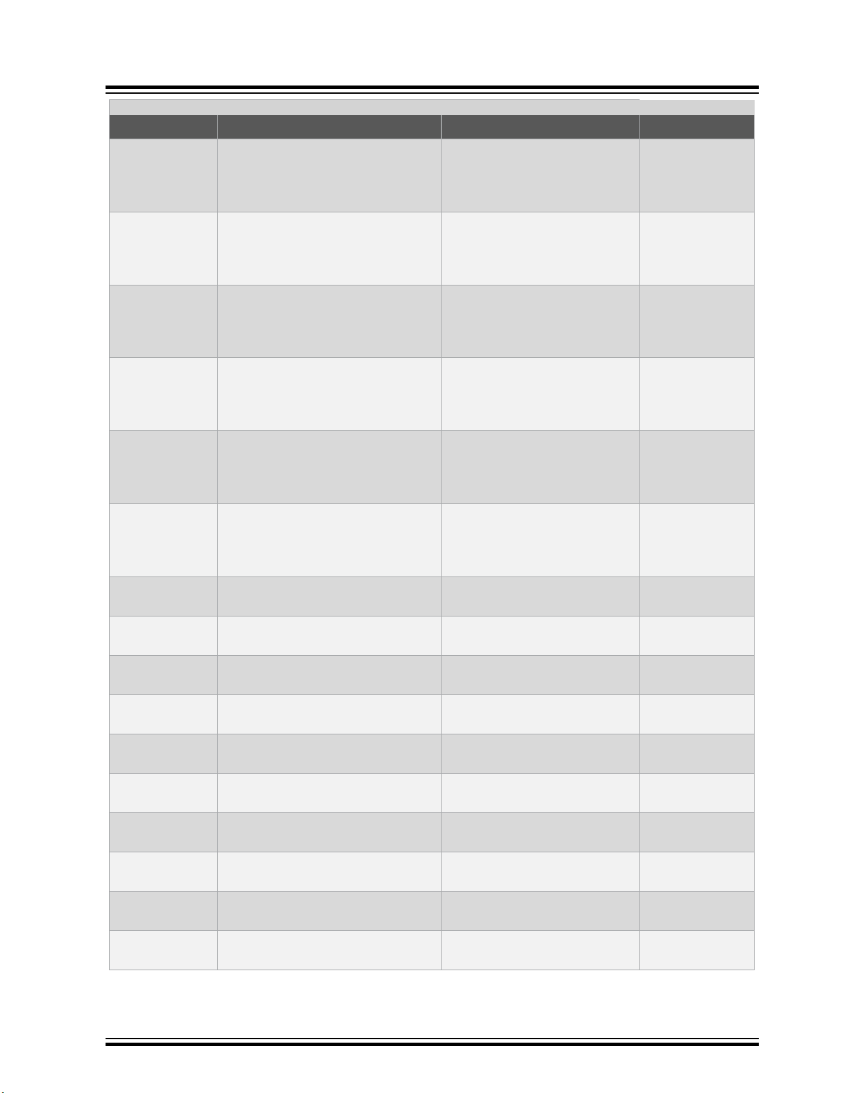
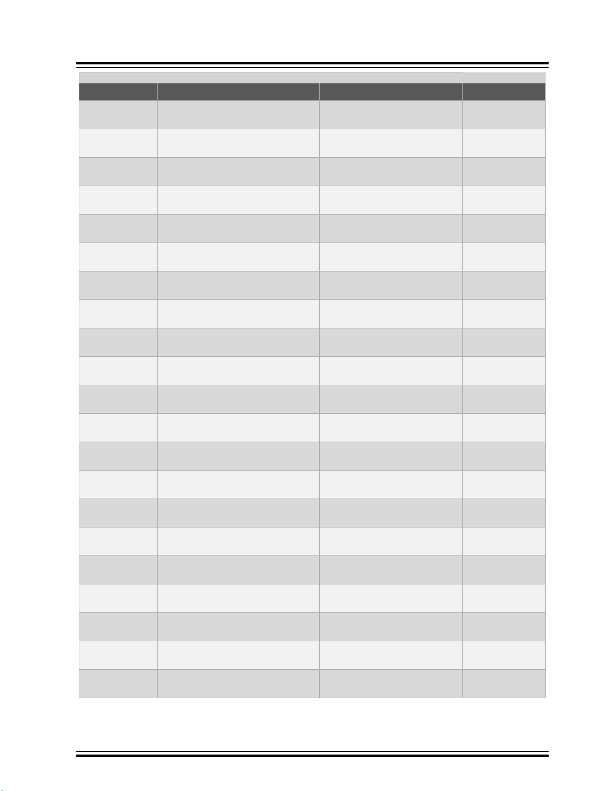
Table 3-1. Device Support
Device Routing Card Socket Card Comment
STK600 Starter Kit
Device Support
AT32UC3A0128 ATSTK600-RC33 - STK600-
RCUC3A144-33
AT32UC3A0256 ATSTK600-RC33 - STK600-
RCUC3A144-33
AT32UC3A0512 ATSTK600-RC33 - STK600-
RCUC3A144-33
AT32UC3A1128 ATSTK600-RC28 - STK600-
RCUC3A100-28
AT32UC3A1256 ATSTK600-RC28 - STK600-
RCUC3A100-28
AT32UC3A1512 ATSTK600-RC28 - STK600-
RCUC3A100-28
AT32UC3A3128 ATSTK600-RC32 - STK600-
RCUC3A144-32
AT32UC3A3128S ATSTK600-RC32 - STK600-
RCUC3A144-32
AT32UC3A3256 ATSTK600-RC32 - STK600-
RCUC3A144-32
AT32UC3A3256S ATSTK600-RC32 - STK600-
RCUC3A144-32
AT32UC3A364 ATSTK600-RC32 - STK600-
RCUC3A144-32
ATSTK600-SC19 - STK600TQFP144
ATSTK600-SC19 - STK600TQFP144
ATSTK600-SC19 - STK600TQFP144
ATSTK600-SC03 - STK600TQFP100
ATSTK600-SC03 - STK600TQFP100
ATSTK600-SC03 - STK600TQFP100
ATSTK600-SC19 - STK600TQFP144
ATSTK600-SC19 - STK600TQFP144
ATSTK600-SC19 - STK600TQFP144
ATSTK600-SC19 - STK600TQFP144
ATSTK600-SC19 - STK600TQFP144
AT32UC3A364S ATSTK600-RC32 - STK600-
RCUC3A144-32
AT32UC3B0128 ATSTK600-RC21 - STK600-
RCUC3B0-21
AT32UC3B0128 ATSTK600-RC21 - STK600-
RCUC3B0-21
AT32UC3B0256 ATSTK600-RC21 - STK600-
RCUC3B0-21
AT32UC3B0256 ATSTK600-RC21 - STK600-
RCUC3B0-21
AT32UC3B0512 ATSTK600-RC21 - STK600-
RCUC3B0-21
AT32UC3B0512 ATSTK600-RC21 - STK600-
RCUC3B0-21
AT32UC3B064 ATSTK600-RC21 - STK600-
RCUC3B0-21
© 2019 Microchip Technology Inc.
ATSTK600-SC19 - STK600TQFP144
ATSTK600-SC14 - STK600TQFP64-2
ATSTK600-SC21 - STK600QFN64
ATSTK600-SC14 - STK600TQFP64-2
ATSTK600-SC21 - STK600QFN64
ATSTK600-SC14 - STK600TQFP64-2
ATSTK600-SC21 - STK600QFN64
ATSTK600-SC14 - STK600TQFP64-2
User Guide
40001904D-page 6
Page 7

STK600 Starter Kit
Device Support
...........continued
Device Routing Card Socket Card Comment
AT32UC3B064 ATSTK600-RC21 - STK600-
RCUC3B0-21
AT32UC3B1128 ATSTK600-RC27 - STK600-
RCUC3B48-27
AT32UC3B1128 ATSTK600-RC27 - STK600-
RCUC3B48-27
AT32UC3B1256 ATSTK600-RC27 - STK600-
RCUC3B48-27
AT32UC3B1256 ATSTK600-RC27 - STK600-
RCUC3B48-27
AT32UC3B1512 ATSTK600-RC27 - STK600-
RCUC3B48-27
AT32UC3B1512 ATSTK600-RC27 - STK600-
RCUC3B48-27
AT32UC3B164 ATSTK600-RC27 - STK600-
RCUC3B48-27
AT32UC3B164 ATSTK600-RC27 - STK600-
RCUC3B48-27
AT32UC3C0128C ATSTK600-RC36 - STK600-
RCUC3C0-36
AT32UC3C0256C ATSTK600-RC36 - STK600-
RCUC3C0-36
ATSTK600-SC21 - STK600QFN64
ATSTK600-SC16 - STK600TQFP48
ATSTK600-SC41 - STK600QFN48
ATSTK600-SC16 - STK600TQFP48
ATSTK600-SC41 - STK600QFN48
ATSTK600-SC16 - STK600TQFP48
ATSTK600-SC41 - STK600QFN48
ATSTK600-SC16 - STK600TQFP48
ATSTK600-SC41 - STK600QFN48
ATSTK600-SC19 - STK600TQFP144
ATSTK600-SC19 - STK600TQFP144
AT32UC3C0512C ATSTK600-RC36 - STK600-
RCUC3C0-36
AT32UC3C064C ATSTK600-RC36 - STK600-
RCUC3C0-36
AT32UC3C1128C ATSTK600-RC38 - STK600-
RCUC3C1-38
AT32UC3C1256C ATSTK600-RC38 - STK600-
RCUC3C1-38
AT32UC3C1512C ATSTK600-RC38 - STK600-
RCUC3C1-38
AT32UC3C164C ATSTK600-RC38 - STK600-
RCUC3C1-38
AT32UC3C2128C ATSTK600-RC40 - STK600-
RCUC3C2-40
AT32UC3C2128C ATSTK600-RC40 - STK600-
RCUC3C2-40
AT32UC3C2256C ATSTK600-RC40 - STK600-
RCUC3C2-40
AT32UC3C2256C ATSTK600-RC40 - STK600-
RCUC3C2-40
ATSTK600-SC19 - STK600TQFP144
ATSTK600-SC19 - STK600TQFP144
ATSTK600-SC03 - STK600TQFP100
ATSTK600-SC03 - STK600TQFP100
ATSTK600-SC03 - STK600TQFP100
ATSTK600-SC03 - STK600TQFP100
ATSTK600-SC14 - STK600TQFP64-2
ATSTK600-SC21 - STK600QFN64
ATSTK600-SC14 - STK600TQFP64-2
ATSTK600-SC21 - STK600QFN64
© 2019 Microchip Technology Inc.
User Guide
40001904D-page 7
Page 8

STK600 Starter Kit
Device Support
...........continued
Device Routing Card Socket Card Comment
AT32UC3C2512C ATSTK600-RC40 - STK600-
RCUC3C2-40
AT32UC3C2512C ATSTK600-RC40 - STK600-
RCUC3C2-40
AT32UC3C264C ATSTK600-RC40 - STK600-
RCUC3C2-40
AT32UC3C264C ATSTK600-RC40 - STK600-
RCUC3C2-40
AT32UC3L0128 ATSTK600-RC34 - STK600-
RCUC3L0-34
AT32UC3L0128 ATSTK600-RC34 - STK600-
RCUC3L0-34
AT32UC3L016 ATSTK600-RC34 - STK600-
RCUC3L0-34
AT32UC3L016 ATSTK600-RC34 - STK600-
RCUC3L0-34
AT32UC3L0256 ATSTK600-RC34 - STK600-
RCUC3L0-34
AT32UC3L0256 ATSTK600-RC34 - STK600-
RCUC3L0-34
AT32UC3L032 ATSTK600-RC34 - STK600-
RCUC3L0-34
ATSTK600-SC14 - STK600TQFP64-2
ATSTK600-SC21 - STK600QFN64
ATSTK600-SC14 - STK600TQFP64-2
ATSTK600-SC21 - STK600QFN64
ATSTK600-SC16 - STK600TQFP48
ATSTK600-SC41 - STK600QFN48
ATSTK600-SC16 - STK600TQFP48
ATSTK600-SC41 - STK600QFN48
ATSTK600-SC16 - STK600TQFP48
ATSTK600-SC41 - STK600QFN48
ATSTK600-SC16 - STK600TQFP48
AT32UC3L032 ATSTK600-RC34 - STK600-
RCUC3L0-34
AT32UC3L064 ATSTK600-RC34 - STK600-
RCUC3L0-34
AT32UC3L064 ATSTK600-RC34 - STK600-
RCUC3L0-34
AT90CAN128 ATSTK600-RC09 - STK600-
RC064M-9
AT90CAN128 ATSTK600-RC09 - STK600-
RC064M-9
AT90CAN32 ATSTK600-RC09 - STK600-
RC064M-9
AT90CAN32 ATSTK600-RC09 - STK600-
RC064M-9
AT90CAN64 ATSTK600-RC09 - STK600-
RC064M-9
AT90CAN64 ATSTK600-RC09 - STK600-
RC064M-9
AT90PWM1 ATSTK600-RC19 - STK600-
RCPWM-19
ATSTK600-SC41 - STK600QFN48
ATSTK600-SC16 - STK600TQFP48
ATSTK600-SC41 - STK600QFN48
ATSTK600-SC02 - STK600TQFP64
ATSTK600-SC21 - STK600QFN64
ATSTK600-SC02 - STK600TQFP64
ATSTK600-SC21 - STK600QFN64
ATSTK600-SC02 - STK600TQFP64
ATSTK600-SC21 - STK600QFN64
ATSTK600-SC11 - STK600-SOIC
© 2019 Microchip Technology Inc.
User Guide
40001904D-page 8
Page 9

STK600 Starter Kit
Device Support
...........continued
Device Routing Card Socket Card Comment
AT90PWM161 ATSTK600-RC26 - STK600-
RCPWM-26
AT90PWM216 ATSTK600-RC19 - STK600-
RCPWM-19
AT90PWM2B ATSTK600-RC19 - STK600-
RCPWM-19
AT90PWM316 ATSTK600-RC19 - STK600-
RCPWM-19
AT90PWM3B ATSTK600-RC19 - STK600-
RCPWM-19
AT90PWM81 ATSTK600-RC26 - STK600-
RCPWM-26
AT90USB1286 ATSTK600-RC17 - STK600-
RC064U-17
AT90USB1286 ATSTK600-RC17 - STK600-
RC064U-17
AT90USB1287 ATSTK600-RC17 - STK600-
RC064U-17
AT90USB1287 ATSTK600-RC17 - STK600-
RC064U-17
AT90USB162 ATSTK600-RC20 - STK600-
RC032U-20
ATSTK600-SC11 - STK600-SOIC
ATSTK600-SC11 - STK600-SOIC
ATSTK600-SC11 - STK600-SOIC
ATSTK600-SC11 - STK600-SOIC
ATSTK600-SC11 - STK600-SOIC
ATSTK600-SC11 - STK600-SOIC
ATSTK600-SC02 - STK600TQFP64
ATSTK600-SC21 - STK600QFN64
ATSTK600-SC02 - STK600TQFP64
ATSTK600-SC21 - STK600QFN64
ATSTK600-SC12 - STK600QFN32
AT90USB162 ATSTK600-RC20 - STK600-
RC032U-20
AT90USB646 ATSTK600-RC17 - STK600-
RC064U-17
AT90USB646 ATSTK600-RC17 - STK600-
RC064U-17
AT90USB647 ATSTK600-RC17 - STK600-
RC064U-17
AT90USB647 ATSTK600-RC17 - STK600-
RC064U-17
AT90USB82 ATSTK600-RC20 - STK600-
RC032U-20
AT90USB82 ATSTK600-RC20 - STK600-
RC032U-20
ATSAMC21E15A ATSTK600-RC89 - STK600-
RC032SAM-89
ATSAMC21E15A ATSTK600-RC89 - STK600-
RC032SAM-89
ATSTK600-SC10 - STK600TQFP32
ATSTK600-SC02 - STK600TQFP64
ATSTK600-SC21 - STK600QFN64
ATSTK600-SC02 - STK600TQFP64
ATSTK600-SC21 - STK600QFN64
ATSTK600-SC12 - STK600QFN32
ATSTK600-SC10 - STK600TQFP32
ATSTK600-SC10 - STK600TQFP32
ATSTK600-SC12 - STK600QFN32
Breakout board
only. STK600
cannot program
this device
Breakout board
only. STK600
cannot program
this device
© 2019 Microchip Technology Inc.
User Guide
40001904D-page 9
Page 10

STK600 Starter Kit
Device Support
...........continued
Device Routing Card Socket Card Comment
ATSAMC21E16A ATSTK600-RC89 - STK600-
RC032SAM-89
ATSAMC21E16A ATSTK600-RC89 - STK600-
RC032SAM-89
ATSAMC21E17A ATSTK600-RC89 - STK600-
RC032SAM-89
ATSAMC21E17A ATSTK600-RC89 - STK600-
RC032SAM-89
ATSAMC21E18A ATSTK600-RC89 - STK600-
RC032SAM-89
ATSAMC21E18A ATSTK600-RC89 - STK600-
RC032SAM-89
ATSTK600-SC10 - STK600TQFP32
ATSTK600-SC12 - STK600QFN32
ATSTK600-SC10 - STK600TQFP32
ATSTK600-SC12 - STK600QFN32
ATSTK600-SC10 - STK600TQFP32
ATSTK600-SC12 - STK600QFN32
Breakout board
only. STK600
cannot program
this device
Breakout board
only. STK600
cannot program
this device
Breakout board
only. STK600
cannot program
this device
Breakout board
only. STK600
cannot program
this device
Breakout board
only. STK600
cannot program
this device
Breakout board
only. STK600
cannot program
this device
ATSAMC21G15A ATSTK600-RC88 - STK600-
RC048SAM-88
ATSAMC21G15A ATSTK600-RC88 - STK600-
RC048SAM-88
ATSAMC21G16A ATSTK600-RC88 - STK600-
RC048SAM-88
ATSAMC21G16A ATSTK600-RC88 - STK600-
RC048SAM-88
ATSAMC21G17A ATSTK600-RC88 - STK600-
RC048SAM-88
ATSTK600-SC16 - STK600TQFP48
ATSTK600-SC41 - STK600QFN48
ATSTK600-SC16 - STK600TQFP48
ATSTK600-SC41 - STK600QFN48
ATSTK600-SC16 - STK600TQFP48
Breakout board
only. STK600
cannot program
this device
Breakout board
only. STK600
cannot program
this device
Breakout board
only. STK600
cannot program
this device
Breakout board
only. STK600
cannot program
this device
Breakout board
only. STK600
cannot program
this device
© 2019 Microchip Technology Inc.
User Guide
40001904D-page 10
Page 11

STK600 Starter Kit
Device Support
...........continued
Device Routing Card Socket Card Comment
ATSAMC21G17A ATSTK600-RC88 - STK600-
RC048SAM-88
ATSAMC21G18A ATSTK600-RC88 - STK600-
RC048SAM-88
ATSAMC21G18A ATSTK600-RC88 - STK600-
RC048SAM-88
ATSAMC21J15A ATSTK600-RC87 - STK600-
RC064SAM-87
ATSAMC21J15A ATSTK600-RC87 - STK600-
RC064SAM-87
ATSAMC21J16A ATSTK600-RC87 - STK600-
RC064SAM-87
ATSTK600-SC41 - STK600QFN48
ATSTK600-SC16 - STK600TQFP48
ATSTK600-SC41 - STK600QFN48
ATSTK600-SC14 - STK600TQFP64-2
ATSTK600-SC21 - STK600QFN64
ATSTK600-SC14 - STK600TQFP64-2
Breakout board
only. STK600
cannot program
this device
Breakout board
only. STK600
cannot program
this device
Breakout board
only. STK600
cannot program
this device
Breakout board
only. STK600
cannot program
this device
Breakout board
only. STK600
cannot program
this device
Breakout board
only. STK600
cannot program
this device
ATSAMC21J16A ATSTK600-RC87 - STK600-
RC064SAM-87
ATSAMC21J17A ATSTK600-RC87 - STK600-
RC064SAM-87
ATSAMC21J17A ATSTK600-RC87 - STK600-
RC064SAM-87
ATSAMC21J17AUATSTK600-RC87 - STK600-
RC064SAM-87
ATSAMC21J17AUATSTK600-RC87 - STK600-
RC064SAM-87
ATSTK600-SC21 - STK600QFN64
ATSTK600-SC14 - STK600TQFP64-2
ATSTK600-SC21 - STK600QFN64
ATSTK600-SC14 - STK600TQFP64-2
ATSTK600-SC21 - STK600QFN64
Breakout board
only. STK600
cannot program
this device
Breakout board
only. STK600
cannot program
this device
Breakout board
only. STK600
cannot program
this device
Breakout board
only. STK600
cannot program
this device
Breakout board
only. STK600
cannot program
this device
© 2019 Microchip Technology Inc.
User Guide
40001904D-page 11
Page 12

STK600 Starter Kit
Device Support
...........continued
Device Routing Card Socket Card Comment
ATSAMC21J18A ATSTK600-RC87 - STK600-
RC064SAM-87
ATSAMC21J18A ATSTK600-RC87 - STK600-
RC064SAM-87
ATSAMC21J18AUATSTK600-RC87 - STK600-
RC064SAM-87
ATSAMC21J18AUATSTK600-RC87 - STK600-
RC064SAM-87
ATSAMC21N17A ATSTK600-RC105 - STK600-
RC100SAM-105
ATSAMC21N18A ATSTK600-RC105 - STK600-
RC100SAM-105
ATSTK600-SC14 - STK600TQFP64-2
ATSTK600-SC21 - STK600QFN64
ATSTK600-SC14 - STK600TQFP64-2
ATSTK600-SC21 - STK600QFN64
ATSTK600-SC03 - STK600TQFP100
ATSTK600-SC03 - STK600TQFP100
Breakout board
only. STK600
cannot program
this device
Breakout board
only. STK600
cannot program
this device
Breakout board
only. STK600
cannot program
this device
Breakout board
only. STK600
cannot program
this device
Breakout board
only. STK600
cannot program
this device
Breakout board
only. STK600
cannot program
this device
ATSAMD09D14A ATSTK600-RC90 - STK600-
RC024SAM-90
ATSAMD10D13AMATSTK600-RC90 - STK600-
RC024SAM-90
ATSAMD10D14AMATSTK600-RC90 - STK600-
RC024SAM-90
ATSAMD11D14AMATSTK600-RC90 - STK600-
RC024SAM-90
ATSAMD20E14 ATSTK600-RC79 - STK600-
RC032SAM-79
ATSTK600-SC62 - STK600QFN24
ATSTK600-SC62 - STK600QFN24
ATSTK600-SC62 - STK600QFN24
ATSTK600-SC62 - STK600QFN24
ATSTK600-SC12 - STK600QFN32
Breakout board
only. STK600
cannot program
this device.
Breakout board
only. STK600
cannot program
this device.
Breakout board
only. STK600
cannot program
this device.
Breakout board
only. STK600
cannot program
this device
Breakout board
only. STK600
cannot program
this device.
© 2019 Microchip Technology Inc.
User Guide
40001904D-page 12
Page 13
STK600 Starter Kit
Device Support
...........continued
Device Routing Card Socket Card Comment
ATSAMD20E14 ATSTK600-RC79 - STK600-
RC032SAM-79
ATSAMD20E14B ATSTK600-RC79 - STK600-
RC032SAM-79
ATSAMD20E14B ATSTK600-RC79 - STK600-
RC032SAM-79
ATSAMD20E15 ATSTK600-RC79 - STK600-
RC032SAM-79
ATSAMD20E15 ATSTK600-RC79 - STK600-
RC032SAM-79
ATSAMD20E15B ATSTK600-RC79 - STK600-
RC032SAM-79
ATSTK600-SC10 - STK600TQFP32
ATSTK600-SC12 - STK600QFN32
ATSTK600-SC10 - STK600TQFP32
ATSTK600-SC12 - STK600QFN32
ATSTK600-SC10 - STK600TQFP32
ATSTK600-SC12 - STK600QFN32
Breakout board
only. STK600
cannot program
this device.
Breakout board
only. STK600
cannot program
this device.
Breakout board
only. STK600
cannot program
this device.
Breakout board
only. STK600
cannot program
this device.
Breakout board
only. STK600
cannot program
this device.
Breakout board
only. STK600
cannot program
this device.
ATSAMD20E15B ATSTK600-RC79 - STK600-
RC032SAM-79
ATSAMD20E16 ATSTK600-RC79 - STK600-
RC032SAM-79
ATSAMD20E16 ATSTK600-RC79 - STK600-
RC032SAM-79
ATSAMD20E16B ATSTK600-RC79 - STK600-
RC032SAM-79
ATSAMD20E16B ATSTK600-RC79 - STK600-
RC032SAM-79
ATSTK600-SC10 - STK600TQFP32
ATSTK600-SC12 - STK600QFN32
ATSTK600-SC10 - STK600TQFP32
ATSTK600-SC12 - STK600QFN32
ATSTK600-SC10 - STK600TQFP32
Breakout board
only. STK600
cannot program
this device.
Breakout board
only. STK600
cannot program
this device.
Breakout board
only. STK600
cannot program
this device.
Breakout board
only. STK600
cannot program
this device.
Breakout board
only. STK600
cannot program
this device.
© 2019 Microchip Technology Inc.
User Guide
40001904D-page 13
Page 14

STK600 Starter Kit
Device Support
...........continued
Device Routing Card Socket Card Comment
ATSAMD20E17 ATSTK600-RC79 - STK600-
RC032SAM-79
ATSAMD20E17 ATSTK600-RC79 - STK600-
RC032SAM-79
ATSAMD20E18 ATSTK600-RC79 - STK600-
RC032SAM-79
ATSAMD20E18 ATSTK600-RC79 - STK600-
RC032SAM-79
ATSAMD20G14 ATSTK600-RC78 - STK600-
RC048SAM-78
ATSAMD20G14 ATSTK600-RC78 - STK600-
RC048SAM-78
ATSTK600-SC12 - STK600QFN32
ATSTK600-SC10 - STK600TQFP32
ATSTK600-SC12 - STK600QFN32
ATSTK600-SC10 - STK600TQFP32
ATSTK600-SC16 - STK600TQFP48
ATSTK600-SC41 - STK600QFN48
Breakout board
only. STK600
cannot program
this device.
Breakout board
only. STK600
cannot program
this device.
Breakout board
only. STK600
cannot program
this device.
Breakout board
only. STK600
cannot program
this device.
Breakout board
only. STK600
cannot program
this device.
Breakout board
only. STK600
cannot program
this device.
ATSAMD20G14B ATSTK600-RC78 - STK600-
RC048SAM-78
ATSAMD20G14B ATSTK600-RC78 - STK600-
RC048SAM-78
ATSAMD20G15 ATSTK600-RC78 - STK600-
RC048SAM-78
ATSAMD20G15 ATSTK600-RC78 - STK600-
RC048SAM-78
ATSAMD20G15B ATSTK600-RC78 - STK600-
RC048SAM-78
ATSTK600-SC16 - STK600TQFP48
ATSTK600-SC41 - STK600QFN48
ATSTK600-SC16 - STK600TQFP48
ATSTK600-SC41 - STK600QFN48
ATSTK600-SC16 - STK600TQFP48
Breakout board
only. STK600
cannot program
this device.
Breakout board
only. STK600
cannot program
this device.
Breakout board
only. STK600
cannot program
this device.
Breakout board
only. STK600
cannot program
this device.
Breakout board
only. STK600
cannot program
this device.
© 2019 Microchip Technology Inc.
User Guide
40001904D-page 14
Page 15

STK600 Starter Kit
Device Support
...........continued
Device Routing Card Socket Card Comment
ATSAMD20G15B ATSTK600-RC78 - STK600-
RC048SAM-78
ATSAMD20G16 ATSTK600-RC78 - STK600-
RC048SAM-78
ATSAMD20G16 ATSTK600-RC78 - STK600-
RC048SAM-78
ATSAMD20G16B ATSTK600-RC78 - STK600-
RC048SAM-78
ATSAMD20G16B ATSTK600-RC78 - STK600-
RC048SAM-78
ATSAMD20G17 ATSTK600-RC78 - STK600-
RC048SAM-78
ATSTK600-SC41 - STK600QFN48
ATSTK600-SC16 - STK600TQFP48
ATSTK600-SC41 - STK600QFN48
ATSTK600-SC16 - STK600TQFP48
ATSTK600-SC41 - STK600QFN48
ATSTK600-SC16 - STK600TQFP48
Breakout board
only. STK600
cannot program
this device.
Breakout board
only. STK600
cannot program
this device.
Breakout board
only. STK600
cannot program
this device.
Breakout board
only. STK600
cannot program
this device.
Breakout board
only. STK600
cannot program
this device.
Breakout board
only. STK600
cannot program
this device.
ATSAMD20G17 ATSTK600-RC78 - STK600-
RC048SAM-78
ATSAMD20G18 ATSTK600-RC78 - STK600-
RC048SAM-78
ATSAMD20G18 ATSTK600-RC78 - STK600-
RC048SAM-78
ATSAMD20J14 ATSTK600-RC72 - STK600-
RC064SAM-72
ATSAMD20J14 ATSTK600-RC72 - STK600-
RC064SAM-72
ATSTK600-SC41 - STK600QFN48
ATSTK600-SC16 - STK600TQFP48
ATSTK600-SC41 - STK600QFN48
ATSTK600-SC14 - STK600TQFP64-2
ATSTK600-SC21 - STK600QFN64
Breakout board
only. STK600
cannot program
this device.
Breakout board
only. STK600
cannot program
this device.
Breakout board
only. STK600
cannot program
this device.
Breakout board
only. STK600
cannot program
this device.
Breakout board
only. STK600
cannot program
this device.
© 2019 Microchip Technology Inc.
User Guide
40001904D-page 15
Page 16

STK600 Starter Kit
Device Support
...........continued
Device Routing Card Socket Card Comment
ATSAMD20J14B ATSTK600-RC72 - STK600-
RC064SAM-72
ATSAMD20J14B ATSTK600-RC72 - STK600-
RC064SAM-72
ATSAMD20J15 ATSTK600-RC72 - STK600-
RC064SAM-72
ATSAMD20J15 ATSTK600-RC72 - STK600-
RC064SAM-72
ATSAMD20J15B ATSTK600-RC72 - STK600-
RC064SAM-72
ATSAMD20J15B ATSTK600-RC72 - STK600-
RC064SAM-72
ATSTK600-SC14 - STK600TQFP64-2
ATSTK600-SC21 - STK600QFN64
ATSTK600-SC14 - STK600TQFP64-2
ATSTK600-SC21 - STK600QFN64
ATSTK600-SC14 - STK600TQFP64-2
ATSTK600-SC21 - STK600QFN64
Breakout board
only. STK600
cannot program
this device.
Breakout board
only. STK600
cannot program
this device.
Breakout board
only. STK600
cannot program
this device.
Breakout board
only. STK600
cannot program
this device.
Breakout board
only. STK600
cannot program
this device.
Breakout board
only. STK600
cannot program
this device.
ATSAMD20J16 ATSTK600-RC72 - STK600-
RC064SAM-72
ATSAMD20J16 ATSTK600-RC72 - STK600-
RC064SAM-72
ATSAMD20J16B ATSTK600-RC72 - STK600-
RC064SAM-72
ATSAMD20J16B ATSTK600-RC72 - STK600-
RC064SAM-72
ATSAMD20J17 ATSTK600-RC72 - STK600-
RC064SAM-72
ATSTK600-SC14 - STK600TQFP64-2
ATSTK600-SC21 - STK600QFN64
ATSTK600-SC14 - STK600TQFP64-2
ATSTK600-SC21 - STK600QFN64
ATSTK600-SC14 - STK600TQFP64-2
Breakout board
only. STK600
cannot program
this device.
Breakout board
only. STK600
cannot program
this device.
Breakout board
only. STK600
cannot program
this device.
Breakout board
only. STK600
cannot program
this device.
Breakout board
only. STK600
cannot program
this device.
© 2019 Microchip Technology Inc.
User Guide
40001904D-page 16
Page 17

STK600 Starter Kit
Device Support
...........continued
Device Routing Card Socket Card Comment
ATSAMD20J17 ATSTK600-RC72 - STK600-
RC064SAM-72
ATSAMD20J18 ATSTK600-RC72 - STK600-
RC064SAM-72
ATSAMD20J18 ATSTK600-RC72 - STK600-
RC064SAM-72
ATSAMD21E15A ATSTK600-RC89 - STK600-
RC032SAM-89
ATSAMD21E15A ATSTK600-RC89 - STK600-
RC032SAM-89
ATSAMD21E15B ATSTK600-RC89 - STK600-
RC032SAM-89
ATSTK600-SC21 - STK600QFN64
ATSTK600-SC14 - STK600TQFP64-2
ATSTK600-SC21 - STK600QFN64
ATSTK600-SC10 - STK600TQFP32
ATSTK600-SC12 - STK600QFN32
ATSTK600-SC10 - STK600TQFP32
Breakout board
only. STK600
cannot program
this device.
Breakout board
only. STK600
cannot program
this device.
Breakout board
only. STK600
cannot program
this device.
Breakout board
only. STK600
cannot program
this device.
Breakout board
only. STK600
cannot program
this device.
Breakout board
only. STK600
cannot program
this device.
ATSAMD21E15B ATSTK600-RC89 - STK600-
RC032SAM-89
ATSAMD21E16A ATSTK600-RC89 - STK600-
RC032SAM-89
ATSAMD21E16A ATSTK600-RC89 - STK600-
RC032SAM-89
ATSAMD21E16B ATSTK600-RC89 - STK600-
RC032SAM-89
ATSAMD21E16B ATSTK600-RC89 - STK600-
RC032SAM-89
ATSTK600-SC12 - STK600QFN32
ATSTK600-SC10 - STK600TQFP32
ATSTK600-SC12 - STK600QFN32
ATSTK600-SC10 - STK600TQFP32
ATSTK600-SC12 - STK600QFN32
Breakout board
only. STK600
cannot program
this device.
Breakout board
only. STK600
cannot program
this device.
Breakout board
only. STK600
cannot program
this device.
Breakout board
only. STK600
cannot program
this device.
Breakout board
only. STK600
cannot program
this device.
© 2019 Microchip Technology Inc.
User Guide
40001904D-page 17
Page 18

STK600 Starter Kit
Device Support
...........continued
Device Routing Card Socket Card Comment
ATSAMD21E17A ATSTK600-RC89 - STK600-
RC032SAM-89
ATSAMD21E17A ATSTK600-RC89 - STK600-
RC032SAM-89
ATSAMD21E18A ATSTK600-RC89 - STK600-
RC032SAM-89
ATSAMD21E18A ATSTK600-RC89 - STK600-
RC032SAM-89
ATSAMD21G15A ATSTK600-RC88 - STK600-
RC048SAM-88
ATSAMD21G15A ATSTK600-RC88 - STK600-
RC048SAM-88
ATSTK600-SC10 - STK600TQFP32
ATSTK600-SC12 - STK600QFN32
ATSTK600-SC10 - STK600TQFP32
ATSTK600-SC12 - STK600QFN32
ATSTK600-SC16 - STK600TQFP48
ATSTK600-SC41 - STK600QFN48
Breakout board
only. STK600
cannot program
this device.
Breakout board
only. STK600
cannot program
this device.
Breakout board
only. STK600
cannot program
this device.
Breakout board
only. STK600
cannot program
this device.
Breakout board
only. STK600
cannot program
this device.
Breakout board
only. STK600
cannot program
this device.
ATSAMD21G15B ATSTK600-RC88 - STK600-
RC048SAM-88
ATSAMD21G15B ATSTK600-RC88 - STK600-
RC048SAM-88
ATSAMD21G16A ATSTK600-RC88 - STK600-
RC048SAM-88
ATSAMD21G16A ATSTK600-RC88 - STK600-
RC048SAM-88
ATSAMD21G16B ATSTK600-RC88 - STK600-
RC048SAM-88
ATSTK600-SC16 - STK600TQFP48
ATSTK600-SC41 - STK600QFN48
ATSTK600-SC16 - STK600TQFP48
ATSTK600-SC41 - STK600QFN48
ATSTK600-SC16 - STK600TQFP48
Breakout board
only. STK600
cannot program
this device.
Breakout board
only. STK600
cannot program
this device.
Breakout board
only. STK600
cannot program
this device.
Breakout board
only. STK600
cannot program
this device.
Breakout board
only. STK600
cannot program
this device.
© 2019 Microchip Technology Inc.
User Guide
40001904D-page 18
Page 19

STK600 Starter Kit
Device Support
...........continued
Device Routing Card Socket Card Comment
ATSAMD21G16B ATSTK600-RC88 - STK600-
RC048SAM-88
ATSAMD21G17A ATSTK600-RC88 - STK600-
RC048SAM-88
ATSAMD21G17A ATSTK600-RC88 - STK600-
RC048SAM-88
ATSAMD21G18A ATSTK600-RC88 - STK600-
RC048SAM-88
ATSAMD21G18A ATSTK600-RC88 - STK600-
RC048SAM-88
ATSAMD21J15A ATSTK600-RC87 - STK600-
RC064SAM-87
ATSTK600-SC41 - STK600QFN48
ATSTK600-SC16 - STK600TQFP48
ATSTK600-SC41 - STK600QFN48
ATSTK600-SC16 - STK600TQFP48
ATSTK600-SC41 - STK600QFN48
ATSTK600-SC14 - STK600TQFP64-2
Breakout board
only. STK600
cannot program
this device.
Breakout board
only. STK600
cannot program
this device.
Breakout board
only. STK600
cannot program
this device.
Breakout board
only. STK600
cannot program
this device.
Breakout board
only. STK600
cannot program
this device.
Breakout board
only. STK600
cannot program
this device.
ATSAMD21J15A ATSTK600-RC87 - STK600-
RC064SAM-87
ATSAMD21J15B ATSTK600-RC87 - STK600-
RC064SAM-87
ATSAMD21J15B ATSTK600-RC87 - STK600-
RC064SAM-87
ATSAMD21J16A ATSTK600-RC87 - STK600-
RC064SAM-87
ATSAMD21J16A ATSTK600-RC87 - STK600-
RC064SAM-87
ATSTK600-SC21 - STK600QFN64
ATSTK600-SC14 - STK600TQFP64-2
ATSTK600-SC21 - STK600QFN64
ATSTK600-SC14 - STK600TQFP64-2
ATSTK600-SC21 - STK600QFN64
Breakout board
only. STK600
cannot program
this device.
Breakout board
only. STK600
cannot program
this device.
Breakout board
only. STK600
cannot program
this device.
Breakout board
only. STK600
cannot program
this device.
Breakout board
only. STK600
cannot program
this device.
© 2019 Microchip Technology Inc.
User Guide
40001904D-page 19
Page 20
STK600 Starter Kit
Device Support
...........continued
Device Routing Card Socket Card Comment
ATSAMD21J16B ATSTK600-RC87 - STK600-
RC064SAM-87
ATSAMD21J16B ATSTK600-RC87 - STK600-
RC064SAM-87
ATSAMD21J17A ATSTK600-RC87 - STK600-
RC064SAM-87
ATSAMD21J17A ATSTK600-RC87 - STK600-
RC064SAM-87
ATSAMD21J18A ATSTK600-RC87 - STK600-
RC064SAM-87
ATSAMD21J18A ATSTK600-RC87 - STK600-
RC064SAM-87
ATSTK600-SC14 - STK600TQFP64-2
ATSTK600-SC21 - STK600QFN64
ATSTK600-SC14 - STK600TQFP64-2
ATSTK600-SC21 - STK600QFN64
ATSTK600-SC14 - STK600TQFP64-2
ATSTK600-SC21 - STK600QFN64
Breakout board
only. STK600
cannot program
this device.
Breakout board
only. STK600
cannot program
this device.
Breakout board
only. STK600
cannot program
this device.
Breakout board
only. STK600
cannot program
this device.
Breakout board
only. STK600
cannot program
this device.
Breakout board
only. STK600
cannot program
this device.
ATUC128D3 ATSTK600-RC48 - STK600-
RCUC3D3-48
ATUC128D3 ATSTK600-RC48 - STK600-
RCUC3D3-48
ATUC128D4 ATSTK600-RC49 - STK600-
RCUC3D4-49
ATUC128D4 ATSTK600-RC49 - STK600-
RCUC3D4-49
ATUC128L3U ATSTK600-RC47 - STK600-
RCUC3L3U-47
ATUC128L3U ATSTK600-RC47 - STK600-
RCUC3L3U-47
ATUC128L4U ATSTK600-RC53 - STK600-
RCUC3L4U-53
ATUC128L4U ATSTK600-RC53 - STK600-
RCUC3L4U-53
ATUC256L3U ATSTK600-RC47 - STK600-
RCUC3L3U-47
ATUC256L3U ATSTK600-RC47 - STK600-
RCUC3L3U-47
ATSTK600-SC14 - STK600TQFP64-2
ATSTK600-SC21 - STK600QFN64
ATSTK600-SC41 - STK600QFN48
ATSTK600-SC16 - STK600TQFP48
ATSTK600-SC14 - STK600TQFP64-2
ATSTK600-SC21 - STK600QFN64
ATSTK600-SC41 - STK600QFN48
ATSTK600-SC16 - STK600TQFP48
ATSTK600-SC14 - STK600TQFP64-2
ATSTK600-SC21 - STK600QFN64
© 2019 Microchip Technology Inc.
User Guide
40001904D-page 20
Page 21

STK600 Starter Kit
Device Support
...........continued
Device Routing Card Socket Card Comment
ATUC256L4U ATSTK600-RC53 - STK600-
RCUC3L4U-53
ATUC256L4U ATSTK600-RC53 - STK600-
RCUC3L4U-53
ATUC64D3 ATSTK600-RC48 - STK600-
RCUC3D3-48
ATUC64D3 ATSTK600-RC48 - STK600-
RCUC3D3-48
ATUC64D4 ATSTK600-RC49 - STK600-
RCUC3D4-49
ATUC64D4 ATSTK600-RC49 - STK600-
RCUC3D4-49
ATUC64L3U ATSTK600-RC47 - STK600-
RCUC3L3U-47
ATUC64L3U ATSTK600-RC47 - STK600-
RCUC3L3U-47
ATUC64L4U ATSTK600-RC53 - STK600-
RCUC3L4U-53
ATUC64L4U ATSTK600-RC53 - STK600-
RCUC3L4U-53
ATmega128 ATSTK600-RC09 - STK600-
RC064M-9
ATSTK600-SC41 - STK600QFN48
ATSTK600-SC16 - STK600TQFP48
ATSTK600-SC14 - STK600TQFP64-2
ATSTK600-SC21 - STK600QFN64
ATSTK600-SC41 - STK600QFN48
ATSTK600-SC16 - STK600TQFP48
ATSTK600-SC14 - STK600TQFP64-2
ATSTK600-SC21 - STK600QFN64
ATSTK600-SC41 - STK600QFN48
ATSTK600-SC16 - STK600TQFP48
ATSTK600-SC02 - STK600TQFP64
ATmega128 ATSTK600-RC09 - STK600-
RC064M-9
ATmega1280 ATSTK600-RC11 - STK600-
RC100M-11
ATmega1281 ATSTK600-RC09 - STK600-
RC064M-9
ATmega1281 ATSTK600-RC09 - STK600-
RC064M-9
ATmega1284 ATSTK600-RC05 - STK600-
RC040M-5
ATmega1284 ATSTK600-RC31 - STK600-
RC044M-31
ATmega1284 ATSTK600-RC31 - STK600-
RC044M-31
ATmega1284P ATSTK600-RC05 - STK600-
RC040M-5
ATmega1284P ATSTK600-RC31 - STK600-
RC044M-31
ATmega1284P ATSTK600-RC31 - STK600-
RC044M-31
ATSTK600-SC21 - STK600QFN64
ATSTK600-SC03 - STK600TQFP100
ATSTK600-SC02 - STK600TQFP64
ATSTK600-SC21 - STK600QFN64
ATSTK600-SC01 - STK600-DIP
ATSTK600-SC06 - STK600TQFP44
ATSTK600-SC45 - STK600QFN44
ATSTK600-SC01 - STK600-DIP
ATSTK600-SC06 - STK600TQFP44
ATSTK600-SC45 - STK600QFN44
© 2019 Microchip Technology Inc.
User Guide
40001904D-page 21
Page 22

STK600 Starter Kit
Device Support
...........continued
Device Routing Card Socket Card Comment
ATmega128A ATSTK600-RC09 - STK600-
RC064M-9
ATmega128A ATSTK600-RC09 - STK600-
RC064M-9
ATmega128RFA1 ATAVR128RFA1-EK1 - STK600-
ATmega16 ATSTK600-RC05 - STK600-
RC040M-5
ATmega16 ATSTK600-RC31 - STK600-
RC044M-31
ATmega16 ATSTK600-RC31 - STK600-
RC044M-31
ATmega1609 ATSTK600-RC107 - STK600-
RC048M-107
ATmega1609 ATSTK600-RC107 - STK600-
RC048M-107
ATmega162 ATSTK600-RC30 - STK600-
RC044M-30
ATmega162 ATSTK600-RC04 - STK600-
RC040M-4
ATmega162 ATSTK600-RC30 - STK600-
RC044M-30
ATSTK600-SC02 - STK600TQFP64
ATSTK600-SC21 - STK600QFN64
ATMEGA128RFA1
ATSTK600-SC01 - STK600-DIP
ATSTK600-SC06 - STK600TQFP44
ATSTK600-SC45 - STK600QFN44
ATSTK600-SC41 - STK600QFN48
ATSTK600-SC16 - STK600TQFP48
ATSTK600-SC06 - STK600TQFP44
ATSTK600-SC01 - STK600-DIP
ATSTK600-SC45 - STK600QFN44
ATmega164A ATSTK600-RC05 - STK600-
RC040M-5
ATmega164A ATSTK600-RC31 - STK600-
RC044M-31
ATmega164A ATSTK600-RC31 - STK600-
RC044M-31
ATmega164P ATSTK600-RC05 - STK600-
RC040M-5
ATmega164P ATSTK600-RC31 - STK600-
RC044M-31
ATmega164P ATSTK600-RC31 - STK600-
RC044M-31
ATmega164PA ATSTK600-RC05 - STK600-
RC040M-5
ATmega164PA ATSTK600-RC31 - STK600-
RC044M-31
ATmega164PA ATSTK600-RC31 - STK600-
RC044M-31
ATmega165A ATSTK600-RC10 - STK600-
RC064M-10
ATSTK600-SC01 - STK600-DIP
ATSTK600-SC06 - STK600TQFP44
ATSTK600-SC45 - STK600QFN44
ATSTK600-SC01 - STK600-DIP
ATSTK600-SC06 - STK600TQFP44
ATSTK600-SC45 - STK600QFN44
ATSTK600-SC01 - STK600-DIP
ATSTK600-SC06 - STK600TQFP44
ATSTK600-SC45 - STK600QFN44
ATSTK600-SC02 - STK600TQFP64
© 2019 Microchip Technology Inc.
User Guide
40001904D-page 22
Page 23

STK600 Starter Kit
Device Support
...........continued
Device Routing Card Socket Card Comment
ATmega165A ATSTK600-RC10 - STK600-
RC064M-10
ATmega165P ATSTK600-RC10 - STK600-
RC064M-10
ATmega165P ATSTK600-RC10 - STK600-
RC064M-10
ATmega165PA ATSTK600-RC10 - STK600-
RC064M-10
ATmega165PA ATSTK600-RC10 - STK600-
RC064M-10
ATmega168 ATSTK600-RC29 - STK600-
RC032M-29
ATmega168 ATSTK600-RC29 - STK600-
RC032M-29
ATmega168 ATSTK600-RC06 - STK600-
RC028M-6
ATmega168A ATSTK600-RC29 - STK600-
RC032M-29
ATmega168A ATSTK600-RC29 - STK600-
RC032M-29
ATmega168A ATSTK600-RC06 - STK600-
RC028M-6
ATSTK600-SC21 - STK600QFN64
ATSTK600-SC02 - STK600TQFP64
ATSTK600-SC21 - STK600QFN64
ATSTK600-SC02 - STK600TQFP64
ATSTK600-SC21 - STK600QFN64
ATSTK600-SC10 - STK600TQFP32
ATSTK600-SC12 - STK600QFN32
ATSTK600-SC01 - STK600-DIP
ATSTK600-SC10 - STK600TQFP32
ATSTK600-SC12 - STK600QFN32
ATSTK600-SC01 - STK600-DIP
ATmega168P ATSTK600-RC29 - STK600-
RC032M-29
ATmega168P ATSTK600-RC29 - STK600-
RC032M-29
ATmega168P ATSTK600-RC06 - STK600-
RC028M-6
ATmega168PA ATSTK600-RC29 - STK600-
RC032M-29
ATmega168PA ATSTK600-RC29 - STK600-
RC032M-29
ATmega168PA ATSTK600-RC06 - STK600-
RC028M-6
ATmega168PB ATSTK600-RC91 - STK600-
RC032M-91
ATmega168PB ATSTK600-RC91 - STK600-
RC032M-91
ATmega169A ATSTK600-RC10 - STK600-
RC064M-10
ATmega169A ATSTK600-RC10 - STK600-
RC064M-10
ATSTK600-SC10 - STK600TQFP32
ATSTK600-SC12 - STK600QFN32
ATSTK600-SC01 - STK600-DIP
ATSTK600-SC10 - STK600TQFP32
ATSTK600-SC12 - STK600QFN32
ATSTK600-SC01 - STK600-DIP
ATSTK600-SC10 - STK600TQFP32
ATSTK600-SC12 - STK600QFN32
ATSTK600-SC02 - STK600TQFP64
ATSTK600-SC21 - STK600QFN64
© 2019 Microchip Technology Inc.
User Guide
40001904D-page 23
Page 24

STK600 Starter Kit
Device Support
...........continued
Device Routing Card Socket Card Comment
ATmega169P ATSTK600-RC10 - STK600-
RC064M-10
ATmega169P ATSTK600-RC10 - STK600-
RC064M-10
ATmega169PA ATSTK600-RC10 - STK600-
RC064M-10
ATmega169PA ATSTK600-RC10 - STK600-
RC064M-10
ATmega16A ATSTK600-RC05 - STK600-
RC040M-5
ATmega16A ATSTK600-RC31 - STK600-
RC044M-31
ATmega16A ATSTK600-RC31 - STK600-
RC044M-31
ATmega16HVB ATSTK600-RC24 - STK600-
RC044M-24
ATmega16HVBrevBATSTK600-RC24 - STK600-
RC044M-24
ATmega16M1 ATSTK600-RC22 - STK600-
RCPWM-22
ATmega16U2 ATSTK600-RC20 - STK600-
RC032U-20
ATSTK600-SC02 - STK600TQFP64
ATSTK600-SC21 - STK600QFN64
ATSTK600-SC02 - STK600TQFP64
ATSTK600-SC21 - STK600QFN64
ATSTK600-SC01 - STK600-DIP
ATSTK600-SC06 - STK600TQFP44
ATSTK600-SC45 - STK600QFN44
ATSTK600-SC13 - STK600TSSOP44
ATSTK600-SC13 - STK600TSSOP44
ATSTK600-SC10 - STK600TQFP32
ATSTK600-SC12 - STK600QFN32
ATmega16U2 ATSTK600-RC20 - STK600-
RC032U-20
ATmega16U4 ATSTK600-RC25 - STK600-
RC044U-25
ATmega16U4 ATSTK600-RC25 - STK600-
RC044U-25
ATmega2560 ATSTK600-RC11 - STK600-
RC100M-11
ATmega2561 ATSTK600-RC09 - STK600-
RC064M-9
ATmega2561 ATSTK600-RC09 - STK600-
RC064M-9
ATmega32 ATSTK600-RC05 - STK600-
RC040M-5
ATmega32 ATSTK600-RC31 - STK600-
RC044M-31
ATmega32 ATSTK600-RC31 - STK600-
RC044M-31
ATmega3209 ATSTK600-RC107 - STK600-
RC048M-107
ATSTK600-SC10 - STK600TQFP32
ATSTK600-SC06 - STK600TQFP44
ATSTK600-SC45 - STK600QFN44
ATSTK600-SC03 - STK600TQFP100
ATSTK600-SC02 - STK600TQFP64
ATSTK600-SC21 - STK600QFN64
ATSTK600-SC01 - STK600-DIP
ATSTK600-SC06 - STK600TQFP44
ATSTK600-SC45 - STK600QFN44
ATSTK600-SC41 - STK600QFN48
© 2019 Microchip Technology Inc.
User Guide
40001904D-page 24
Page 25
STK600 Starter Kit
Device Support
...........continued
Device Routing Card Socket Card Comment
ATmega3209 ATSTK600-RC107 - STK600-
RC048M-107
ATmega324A ATSTK600-RC05 - STK600-
RC040M-5
ATmega324A ATSTK600-RC31 - STK600-
RC044M-31
ATmega324A ATSTK600-RC31 - STK600-
RC044M-31
ATmega324P ATSTK600-RC05 - STK600-
RC040M-5
ATmega324P ATSTK600-RC31 - STK600-
RC044M-31
ATmega324P ATSTK600-RC31 - STK600-
RC044M-31
ATmega324PA ATSTK600-RC05 - STK600-
RC040M-5
ATmega324PA ATSTK600-RC31 - STK600-
RC044M-31
ATmega324PA ATSTK600-RC31 - STK600-
RC044M-31
ATmega324PB ATSTK600-RC101 - STK600-
RC044M-101
ATSTK600-SC16 - STK600TQFP48
ATSTK600-SC01 - STK600-DIP
ATSTK600-SC06 - STK600TQFP44
ATSTK600-SC45 - STK600QFN44
ATSTK600-SC01 - STK600-DIP
ATSTK600-SC06 - STK600TQFP44
ATSTK600-SC45 - STK600QFN44
ATSTK600-SC01 - STK600-DIP
ATSTK600-SC06 - STK600TQFP44
ATSTK600-SC45 - STK600QFN44
ATSTK600-SC06 - STK600TQFP44
ATmega324PB ATSTK600-RC101 - STK600-
RC044M-101
ATmega325 ATSTK600-RC10 - STK600-
RC064M-10
ATmega325 ATSTK600-RC10 - STK600-
RC064M-10
ATmega3250 ATSTK600-RC18 - STK600-
RC100M-18
ATmega3250A ATSTK600-RC18 - STK600-
RC100M-18
ATmega3250P ATSTK600-RC18 - STK600-
RC100M-18
ATmega3250PA ATSTK600-RC18 - STK600-
RC100M-18
ATmega325A ATSTK600-RC10 - STK600-
RC064M-10
ATmega325A ATSTK600-RC10 - STK600-
RC064M-10
ATmega325P ATSTK600-RC10 - STK600-
RC064M-10
ATSTK600-SC45 - STK600QFN44
ATSTK600-SC02 - STK600TQFP64
ATSTK600-SC21 - STK600QFN64
ATSTK600-SC03 - STK600TQFP100
ATSTK600-SC03 - STK600TQFP100
ATSTK600-SC03 - STK600TQFP100
ATSTK600-SC03 - STK600TQFP100
ATSTK600-SC02 - STK600TQFP64
ATSTK600-SC21 - STK600QFN64
ATSTK600-SC02 - STK600TQFP64
© 2019 Microchip Technology Inc.
User Guide
40001904D-page 25
Page 26

STK600 Starter Kit
Device Support
...........continued
Device Routing Card Socket Card Comment
ATmega325P ATSTK600-RC10 - STK600-
RC064M-10
ATmega325PA ATSTK600-RC10 - STK600-
RC064M-10
ATmega325PA ATSTK600-RC10 - STK600-
RC064M-10
ATmega328 ATSTK600-RC29 - STK600-
RC032M-29
ATmega328 ATSTK600-RC29 - STK600-
RC032M-29
ATmega328 ATSTK600-RC06 - STK600-
RC028M-6
ATmega328P ATSTK600-RC29 - STK600-
RC032M-29
ATmega328P ATSTK600-RC29 - STK600-
RC032M-29
ATmega328P ATSTK600-RC06 - STK600-
RC028M-6
ATmega328PB ATSTK600-RC91 - STK600-
RC032M-91
ATmega328PB ATSTK600-RC91 - STK600-
RC032M-91
ATSTK600-SC21 - STK600QFN64
ATSTK600-SC02 - STK600TQFP64
ATSTK600-SC21 - STK600QFN64
ATSTK600-SC10 - STK600TQFP32
ATSTK600-SC12 - STK600QFN32
ATSTK600-SC01 - STK600-DIP
ATSTK600-SC10 - STK600TQFP32
ATSTK600-SC12 - STK600QFN32
ATSTK600-SC01 - STK600-DIP
ATSTK600-SC10 - STK600TQFP32
ATSTK600-SC12 - STK600QFN32
ATmega329 ATSTK600-RC10 - STK600-
RC064M-10
ATmega329 ATSTK600-RC10 - STK600-
RC064M-10
ATmega3290 ATSTK600-RC18 - STK600-
RC100M-18
ATmega3290A ATSTK600-RC18 - STK600-
RC100M-18
ATmega3290P ATSTK600-RC18 - STK600-
RC100M-18
ATmega3290PA ATSTK600-RC18 - STK600-
RC100M-18
ATmega329A ATSTK600-RC10 - STK600-
RC064M-10
ATmega329A ATSTK600-RC10 - STK600-
RC064M-10
ATmega329P ATSTK600-RC10 - STK600-
RC064M-10
ATmega329P ATSTK600-RC10 - STK600-
RC064M-10
ATSTK600-SC02 - STK600TQFP64
ATSTK600-SC21 - STK600QFN64
ATSTK600-SC03 - STK600TQFP100
ATSTK600-SC03 - STK600TQFP100
ATSTK600-SC03 - STK600TQFP100
ATSTK600-SC03 - STK600TQFP100
ATSTK600-SC02 - STK600TQFP64
ATSTK600-SC21 - STK600QFN64
ATSTK600-SC02 - STK600TQFP64
ATSTK600-SC21 - STK600QFN64
© 2019 Microchip Technology Inc.
User Guide
40001904D-page 26
Page 27

STK600 Starter Kit
Device Support
...........continued
Device Routing Card Socket Card Comment
ATmega329PA ATSTK600-RC10 - STK600-
RC064M-10
ATmega329PA ATSTK600-RC10 - STK600-
RC064M-10
ATmega32A ATSTK600-RC05 - STK600-
RC040M-5
ATmega32A ATSTK600-RC31 - STK600-
RC044M-31
ATmega32A ATSTK600-RC31 - STK600-
RC044M-31
ATmega32C1 ATSTK600-RC22 - STK600-
RCPWM-22
ATmega32HVB ATSTK600-RC24 - STK600-
RC044M-24
ATmega32HVBrevBATSTK600-RC24 - STK600-
RC044M-24
ATmega32M1 ATSTK600-RC22 - STK600-
RCPWM-22
ATmega32U2 ATSTK600-RC20 - STK600-
RC032U-20
ATmega32U2 ATSTK600-RC20 - STK600-
RC032U-20
ATSTK600-SC02 - STK600TQFP64
ATSTK600-SC21 - STK600QFN64
ATSTK600-SC01 - STK600-DIP
ATSTK600-SC06 - STK600TQFP44
ATSTK600-SC45 - STK600QFN44
ATSTK600-SC10 - STK600TQFP32
ATSTK600-SC13 - STK600TSSOP44
ATSTK600-SC13 - STK600TSSOP44
ATSTK600-SC10 - STK600TQFP32
ATSTK600-SC12 - STK600QFN32
ATSTK600-SC10 - STK600TQFP32
ATmega32U4 ATSTK600-RC25 - STK600-
RC044U-25
ATmega32U4 ATSTK600-RC25 - STK600-
RC044U-25
ATmega48 ATSTK600-RC29 - STK600-
RC032M-29
ATmega48 ATSTK600-RC29 - STK600-
RC032M-29
ATmega48 ATSTK600-RC06 - STK600-
RC028M-6
ATmega4809 ATSTK600-RC107 - STK600-
RC048M-107
ATmega4809 ATSTK600-RC107 - STK600-
RC048M-107
ATmega48A ATSTK600-RC29 - STK600-
RC032M-29
ATmega48A ATSTK600-RC29 - STK600-
RC032M-29
ATmega48A ATSTK600-RC06 - STK600-
RC028M-6
ATSTK600-SC06 - STK600TQFP44
ATSTK600-SC45 - STK600QFN44
ATSTK600-SC10 - STK600TQFP32
ATSTK600-SC12 - STK600QFN32
ATSTK600-SC01 - STK600-DIP
ATSTK600-SC41 - STK600QFN48
ATSTK600-SC16 - STK600TQFP48
ATSTK600-SC10 - STK600TQFP32
ATSTK600-SC12 - STK600QFN32
ATSTK600-SC01 - STK600-DIP
© 2019 Microchip Technology Inc.
User Guide
40001904D-page 27
Page 28

STK600 Starter Kit
Device Support
...........continued
Device Routing Card Socket Card Comment
ATmega48P ATSTK600-RC29 - STK600-
RC032M-29
ATmega48P ATSTK600-RC29 - STK600-
RC032M-29
ATmega48P ATSTK600-RC06 - STK600-
RC028M-6
ATmega48PA ATSTK600-RC29 - STK600-
RC032M-29
ATmega48PA ATSTK600-RC29 - STK600-
RC032M-29
ATmega48PA ATSTK600-RC06 - STK600-
RC028M-6
ATmega48PB ATSTK600-RC91 - STK600-
RC032M-91
ATmega48PB ATSTK600-RC91 - STK600-
RC032M-91
ATmega64 ATSTK600-RC09 - STK600-
RC064M-9
ATmega64 ATSTK600-RC09 - STK600-
RC064M-9
ATmega640 ATSTK600-RC11 - STK600-
RC100M-11
ATSTK600-SC10 - STK600TQFP32
ATSTK600-SC12 - STK600QFN32
ATSTK600-SC01 - STK600-DIP
ATSTK600-SC10 - STK600TQFP32
ATSTK600-SC12 - STK600QFN32
ATSTK600-SC01 - STK600-DIP
ATSTK600-SC10 - STK600TQFP32
ATSTK600-SC12 - STK600QFN32
ATSTK600-SC02 - STK600TQFP64
ATSTK600-SC21 - STK600QFN64
ATSTK600-SC03 - STK600TQFP100
ATmega644 ATSTK600-RC05 - STK600-
RC040M-5
ATmega644 ATSTK600-RC31 - STK600-
RC044M-31
ATmega644 ATSTK600-RC31 - STK600-
RC044M-31
ATmega644A ATSTK600-RC05 - STK600-
RC040M-5
ATmega644A ATSTK600-RC31 - STK600-
RC044M-31
ATmega644A ATSTK600-RC31 - STK600-
RC044M-31
ATmega644P ATSTK600-RC05 - STK600-
RC040M-5
ATmega644P ATSTK600-RC31 - STK600-
RC044M-31
ATmega644P ATSTK600-RC31 - STK600-
RC044M-31
ATmega644PA ATSTK600-RC05 - STK600-
RC040M-5
ATSTK600-SC01 - STK600-DIP
ATSTK600-SC06 - STK600TQFP44
ATSTK600-SC45 - STK600QFN44
ATSTK600-SC01 - STK600-DIP
ATSTK600-SC06 - STK600TQFP44
ATSTK600-SC45 - STK600QFN44
ATSTK600-SC01 - STK600-DIP
ATSTK600-SC06 - STK600TQFP44
ATSTK600-SC45 - STK600QFN44
ATSTK600-SC01 - STK600-DIP
© 2019 Microchip Technology Inc.
User Guide
40001904D-page 28
Page 29

STK600 Starter Kit
Device Support
...........continued
Device Routing Card Socket Card Comment
ATmega644PA ATSTK600-RC31 - STK600-
RC044M-31
ATmega644PA ATSTK600-RC31 - STK600-
RC044M-31
ATmega645 ATSTK600-RC10 - STK600-
RC064M-10
ATmega645 ATSTK600-RC10 - STK600-
RC064M-10
ATmega6450 ATSTK600-RC18 - STK600-
RC100M-18
ATmega6450A ATSTK600-RC18 - STK600-
RC100M-18
ATmega6450P ATSTK600-RC18 - STK600-
RC100M-18
ATmega645A ATSTK600-RC10 - STK600-
RC064M-10
ATmega645A ATSTK600-RC10 - STK600-
RC064M-10
ATmega645P ATSTK600-RC10 - STK600-
RC064M-10
ATmega645P ATSTK600-RC10 - STK600-
RC064M-10
ATSTK600-SC06 - STK600TQFP44
ATSTK600-SC45 - STK600QFN44
ATSTK600-SC02 - STK600TQFP64
ATSTK600-SC21 - STK600QFN64
ATSTK600-SC03 - STK600TQFP100
ATSTK600-SC03 - STK600TQFP100
ATSTK600-SC03 - STK600TQFP100
ATSTK600-SC02 - STK600TQFP64
ATSTK600-SC21 - STK600QFN64
ATSTK600-SC02 - STK600TQFP64
ATSTK600-SC21 - STK600QFN64
ATmega649 ATSTK600-RC10 - STK600-
RC064M-10
ATmega649 ATSTK600-RC10 - STK600-
RC064M-10
ATmega6490 ATSTK600-RC18 - STK600-
RC100M-18
ATmega6490A ATSTK600-RC18 - STK600-
RC100M-18
ATmega6490P ATSTK600-RC18 - STK600-
RC100M-18
ATmega649A ATSTK600-RC10 - STK600-
RC064M-10
ATmega649A ATSTK600-RC10 - STK600-
RC064M-10
ATmega649P ATSTK600-RC10 - STK600-
RC064M-10
ATmega649P ATSTK600-RC10 - STK600-
RC064M-10
ATmega64A ATSTK600-RC09 - STK600-
RC064M-9
ATSTK600-SC02 - STK600TQFP64
ATSTK600-SC21 - STK600QFN64
ATSTK600-SC03 - STK600TQFP100
ATSTK600-SC03 - STK600TQFP100
ATSTK600-SC03 - STK600TQFP100
ATSTK600-SC02 - STK600TQFP64
ATSTK600-SC21 - STK600QFN64
ATSTK600-SC02 - STK600TQFP64
ATSTK600-SC21 - STK600QFN64
ATSTK600-SC02 - STK600TQFP64
© 2019 Microchip Technology Inc.
User Guide
40001904D-page 29
Page 30

STK600 Starter Kit
Device Support
...........continued
Device Routing Card Socket Card Comment
ATmega64A ATSTK600-RC09 - STK600-
RC064M-9
ATmega64C1 ATSTK600-RC22 - STK600-
RCPWM-22
ATmega64M1 ATSTK600-RC22 - STK600-
RCPWM-22
ATmega8 ATSTK600-RC29 - STK600-
RC032M-29
ATmega8 ATSTK600-RC29 - STK600-
RC032M-29
ATmega8 ATSTK600-RC06 - STK600-
RC028M-6
ATmega809 ATSTK600-RC107 - STK600-
RC048M-107
ATmega809 ATSTK600-RC107 - STK600-
RC048M-107
ATmega8515 ATSTK600-RC30 - STK600-
RC044M-30
ATmega8515 ATSTK600-RC04 - STK600-
RC040M-4
ATmega8515 ATSTK600-RC30 - STK600-
RC044M-30
ATSTK600-SC21 - STK600QFN64
ATSTK600-SC10 - STK600TQFP32
ATSTK600-SC10 - STK600TQFP32
ATSTK600-SC10 - STK600TQFP32
ATSTK600-SC12 - STK600QFN32
ATSTK600-SC01 - STK600-DIP
ATSTK600-SC41 - STK600QFN48
ATSTK600-SC16 - STK600TQFP48
ATSTK600-SC06 - STK600TQFP44
ATSTK600-SC01 - STK600-DIP
ATSTK600-SC45 - STK600QFN44
ATmega8535 ATSTK600-RC05 - STK600-
RC040M-5
ATmega8535 ATSTK600-RC31 - STK600-
RC044M-31
ATmega8535 ATSTK600-RC31 - STK600-
RC044M-31
ATmega88 ATSTK600-RC29 - STK600-
RC032M-29
ATmega88 ATSTK600-RC29 - STK600-
RC032M-29
ATmega88 ATSTK600-RC06 - STK600-
RC028M-6
ATmega88A ATSTK600-RC29 - STK600-
RC032M-29
ATmega88A ATSTK600-RC29 - STK600-
RC032M-29
ATmega88A ATSTK600-RC06 - STK600-
RC028M-6
ATmega88P ATSTK600-RC29 - STK600-
RC032M-29
ATSTK600-SC01 - STK600-DIP
ATSTK600-SC06 - STK600TQFP44
ATSTK600-SC45 - STK600QFN44
ATSTK600-SC10 - STK600TQFP32
ATSTK600-SC12 - STK600QFN32
ATSTK600-SC01 - STK600-DIP
ATSTK600-SC10 - STK600TQFP32
ATSTK600-SC12 - STK600QFN32
ATSTK600-SC01 - STK600-DIP
ATSTK600-SC10 - STK600TQFP32
© 2019 Microchip Technology Inc.
User Guide
40001904D-page 30
Page 31

STK600 Starter Kit
Device Support
...........continued
Device Routing Card Socket Card Comment
ATmega88P ATSTK600-RC29 - STK600-
RC032M-29
ATmega88P ATSTK600-RC06 - STK600-
RC028M-6
ATmega88PA ATSTK600-RC29 - STK600-
RC032M-29
ATmega88PA ATSTK600-RC29 - STK600-
RC032M-29
ATmega88PA ATSTK600-RC06 - STK600-
RC028M-6
ATmega88PB ATSTK600-RC91 - STK600-
RC032M-91
ATmega88PB ATSTK600-RC91 - STK600-
RC032M-91
ATmega8A ATSTK600-RC29 - STK600-
RC032M-29
ATmega8A ATSTK600-RC29 - STK600-
RC032M-29
ATmega8A ATSTK600-RC06 - STK600-
RC028M-6
ATmega8U2 ATSTK600-RC20 - STK600-
RC032U-20
ATSTK600-SC12 - STK600QFN32
ATSTK600-SC01 - STK600-DIP
ATSTK600-SC10 - STK600TQFP32
ATSTK600-SC12 - STK600QFN32
ATSTK600-SC01 - STK600-DIP
ATSTK600-SC10 - STK600TQFP32
ATSTK600-SC12 - STK600QFN32
ATSTK600-SC10 - STK600TQFP32
ATSTK600-SC12 - STK600QFN32
ATSTK600-SC01 - STK600-DIP
ATSTK600-SC12 - STK600QFN32
ATmega8U2 ATSTK600-RC20 - STK600-
RC032U-20
ATtiny10 ATSTK600-ATTINY10 - STK600-
ATtiny102 ATSTK600-RC102 - STK600-
RC014T-102
ATtiny104 ATSTK600-RC102 - STK600-
RC014T-102
ATtiny11 ATSTK600-RC02 - STK600-RC008T-2 ATSTK600-SC01 - STK600-DIP
ATtiny12 ATSTK600-RC02 - STK600-RC008T-2 ATSTK600-SC01 - STK600-DIP
ATtiny13 ATSTK600-RC02 - STK600-RC008T-2 ATSTK600-SC01 - STK600-DIP
ATtiny13A ATSTK600-RC02 - STK600-RC008T-2 ATSTK600-SC01 - STK600-DIP
ATtiny1604 ATSTK600-RC104 - STK600-
RC020T-104
ATtiny1606 ATSTK600-RC104 - STK600-
RC020T-104
ATtiny1607 ATSTK600-RC103 - STK600-
RC024T-103
ATtiny1614 ATSTK600-RC104 - STK600-
RC020T-104
ATSTK600-SC10 - STK600TQFP32
ATTINY10
ATSTK600-SC11 - STK600-SOIC
ATSTK600-SC11 - STK600-SOIC
ATSTK600-SC11 - STK600-SOIC
ATSTK600-SC11 - STK600-SOIC
ATSTK600-SC62 - STK600QFN24
ATSTK600-SC11 - STK600-SOIC
© 2019 Microchip Technology Inc.
User Guide
40001904D-page 31
Page 32

STK600 Starter Kit
Device Support
...........continued
Device Routing Card Socket Card Comment
ATtiny1616 ATSTK600-RC104 - STK600-
RC020T-104
ATtiny1617 ATSTK600-RC103 - STK600-
RC024T-103
ATtiny1634 ATSTK600-RC54 - STK600-
RC020T-54
ATtiny167 ATSTK600-RC23 - STK600-
RC020T-23
ATtiny20 ATSTK600-RC42 - STK600-
RC014T-42
ATtiny204 ATSTK600-RC104 - STK600-
RC020T-104
ATtiny214 ATSTK600-RC104 - STK600-
RC020T-104
ATtiny2313 ATSTK600-RC01 - STK600-RC020T-1 ATSTK600-SC01 - STK600-DIP
ATtiny2313A ATSTK600-RC01 - STK600-RC020T-1 ATSTK600-SC01 - STK600-DIP
ATtiny24 ATSTK600-RC12 - STK600-
RC014T-12
ATtiny24 ATSTK600-RC46 - STK600-
RC014T-46
ATSTK600-SC11 - STK600-SOIC
ATSTK600-SC62 - STK600QFN24
ATSTK600-SC11 - STK600-SOIC
ATSTK600-SC11 - STK600-SOIC
ATSTK600-SC11 - STK600-SOIC
ATSTK600-SC11 - STK600-SOIC
ATSTK600-SC11 - STK600-SOIC
ATSTK600-SC01 - STK600-DIP
ATSTK600-SC11 - STK600-SOIC
ATtiny24A ATSTK600-RC12 - STK600-
RC014T-12
ATtiny24A ATSTK600-RC46 - STK600-
RC014T-46
ATtiny25 ATSTK600-RC02 - STK600-RC008T-2 ATSTK600-SC01 - STK600-DIP
ATtiny26 ATSTK600-RC08 - STK600-RC020T-8 ATSTK600-SC01 - STK600-DIP
ATtiny261 ATSTK600-RC08 - STK600-RC020T-8 ATSTK600-SC01 - STK600-DIP
ATtiny261A ATSTK600-RC08 - STK600-RC020T-8 ATSTK600-SC01 - STK600-DIP
ATtiny3204 ATSTK600-RC104 - STK600-
RC020T-104
ATtiny3206 ATSTK600-RC104 - STK600-
RC020T-104
ATtiny3207 ATSTK600-RC103 - STK600-
RC024T-103
ATtiny3214 ATSTK600-RC104 - STK600-
RC020T-104
ATtiny3216 ATSTK600-RC104 - STK600-
RC020T-104
ATtiny3217 ATSTK600-RC103 - STK600-
RC024T-103
ATSTK600-SC01 - STK600-DIP
ATSTK600-SC11 - STK600-SOIC
ATSTK600-SC11 - STK600-SOIC
ATSTK600-SC11 - STK600-SOIC
ATSTK600-SC62 - STK600QFN24
ATSTK600-SC11 - STK600-SOIC
ATSTK600-SC11 - STK600-SOIC
ATSTK600-SC62 - STK600QFN24
ATtiny4 ATSTK600-ATTINY10 - STK600-
ATTINY10
© 2019 Microchip Technology Inc.
User Guide
40001904D-page 32
Page 33

STK600 Starter Kit
Device Support
...........continued
Device Routing Card Socket Card Comment
ATtiny40 ATSTK600-RC44 - STK600-
RC020T-44
ATtiny404 ATSTK600-RC104 - STK600-
RC020T-104
ATtiny406 ATSTK600-RC104 - STK600-
RC020T-104
ATtiny414 ATSTK600-RC104 - STK600-
RC020T-104
ATtiny416 ATSTK600-RC104 - STK600-
RC020T-104
ATtiny416auto ATSTK600-RC104 - STK600-
RC020T-104
ATtiny417 ATSTK600-RC103 - STK600-
RC024T-103
ATtiny4313 ATSTK600-RC01 - STK600-RC020T-1 ATSTK600-SC01 - STK600-DIP
ATtiny43U ATSTK600-Tinyx3U - STK600-
ATtiny44 ATSTK600-RC12 - STK600-
RC014T-12
ATtiny44 ATSTK600-RC46 - STK600-
RC014T-46
ATSTK600-SC11 - STK600-SOIC
ATSTK600-SC11 - STK600-SOIC
ATSTK600-SC11 - STK600-SOIC
ATSTK600-SC11 - STK600-SOIC
ATSTK600-SC11 - STK600-SOIC
ATSTK600-SC11 - STK600-SOIC
ATSTK600-SC62 - STK600QFN24
TINYX3U
ATSTK600-SC01 - STK600-DIP
ATSTK600-SC11 - STK600-SOIC
ATtiny441 ATSTK600-RC46 - STK600-
RC014T-46
ATtiny44A ATSTK600-RC12 - STK600-
RC014T-12
ATtiny44A ATSTK600-RC46 - STK600-
RC014T-46
ATtiny45 ATSTK600-RC02 - STK600-RC008T-2 ATSTK600-SC01 - STK600-DIP
ATtiny461 ATSTK600-RC08 - STK600-RC020T-8 ATSTK600-SC01 - STK600-DIP
ATtiny461A ATSTK600-RC08 - STK600-RC020T-8 ATSTK600-SC01 - STK600-DIP
ATtiny48 ATSTK600-RC06 - STK600-
RC028M-6
ATtiny48 ATSTK600-RC45 - STK600-
RC032T-45
ATtiny48 ATSTK600-RC45 - STK600-
RC032T-45
ATtiny5 ATSTK600-ATTINY10 - STK600-
ATtiny804 ATSTK600-RC104 - STK600-
RC020T-104
ATtiny806 ATSTK600-RC104 - STK600-
RC020T-104
ATSTK600-SC11 - STK600-SOIC
ATSTK600-SC01 - STK600-DIP
ATSTK600-SC11 - STK600-SOIC
ATSTK600-SC01 - STK600-DIP
ATSTK600-SC10 - STK600TQFP32
ATSTK600-SC12 - STK600QFN32
ATTINY10
ATSTK600-SC11 - STK600-SOIC
ATSTK600-SC11 - STK600-SOIC
© 2019 Microchip Technology Inc.
User Guide
40001904D-page 33
Page 34

STK600 Starter Kit
Device Support
...........continued
Device Routing Card Socket Card Comment
ATtiny807 ATSTK600-RC103 - STK600-
RC024T-103
ATtiny814 ATSTK600-RC104 - STK600-
RC020T-104
ATtiny816 ATSTK600-RC104 - STK600-
RC020T-104
ATtiny817 ATSTK600-RC103 - STK600-
RC024T-103
ATtiny828 ATSTK600-RC56 - STK600-
RC032T-56
ATtiny828 ATSTK600-RC56 - STK600-
RC032T-56
ATtiny84 ATSTK600-RC12 - STK600-
RC014T-12
ATtiny84 ATSTK600-RC46 - STK600-
RC014T-46
ATtiny841 ATSTK600-RC46 - STK600-
RC014T-46
ATtiny84A ATSTK600-RC12 - STK600-
RC014T-12
ATtiny84A ATSTK600-RC46 - STK600-
RC014T-46
ATSTK600-SC62 - STK600QFN24
ATSTK600-SC11 - STK600-SOIC
ATSTK600-SC11 - STK600-SOIC
ATSTK600-SC62 - STK600QFN24
ATSTK600-SC10 - STK600TQFP32
ATSTK600-SC12 - STK600QFN32
ATSTK600-SC01 - STK600-DIP
ATSTK600-SC11 - STK600-SOIC
ATSTK600-SC11 - STK600-SOIC
ATSTK600-SC01 - STK600-DIP
ATSTK600-SC11 - STK600-SOIC
ATtiny85 ATSTK600-RC02 - STK600-RC008T-2 ATSTK600-SC01 - STK600-DIP
ATtiny861 ATSTK600-RC08 - STK600-RC020T-8 ATSTK600-SC01 - STK600-DIP
ATtiny861A ATSTK600-RC08 - STK600-RC020T-8 ATSTK600-SC01 - STK600-DIP
ATtiny87 ATSTK600-RC23 - STK600-
RC020T-23
ATtiny88 ATSTK600-RC06 - STK600-
RC028M-6
ATtiny88 ATSTK600-RC45 - STK600-
RC032T-45
ATtiny88 ATSTK600-RC45 - STK600-
RC032T-45
ATtiny9 ATSTK600-ATTINY10 - STK600-
ATxmega128A1 ATSTK600-RC13 - STK600-
RC100X-13
ATxmega128A1 ATSTK600-RC13 - STK600-
RC100X-13
ATxmega128A1U ATSTK600-RC13 - STK600-
RC100X-13
ATSTK600-SC11 - STK600-SOIC
ATSTK600-SC01 - STK600-DIP
ATSTK600-SC10 - STK600TQFP32
ATSTK600-SC12 - STK600QFN32
ATTINY10
ATSTK600-SC03 - STK600TQFP100
ATSTK600-SC03 - STK600TQFP100
ATSTK600-SC03 - STK600TQFP100
since rev.10
(A09-0117/10)
© 2019 Microchip Technology Inc.
User Guide
40001904D-page 34
Page 35

STK600 Starter Kit
Device Support
...........continued
Device Routing Card Socket Card Comment
ATxmega128A1U ATSTK600-RC13 - STK600-
RC100X-13
ATxmega128A3 ATSTK600-RC14 - STK600-
RC064X-14
ATxmega128A3 ATSTK600-RC51 - STK600-
RC064X-51
ATxmega128A3 ATSTK600-RC14 - STK600-
RC064X-14
ATxmega128A3 ATSTK600-RC51 - STK600-
RC064X-51
ATxmega128A3U ATSTK600-RC51 - STK600-
RC064X-51
ATxmega128A3U ATSTK600-RC51 - STK600-
RC064X-51
ATxmega128A4U ATSTK600-RC55 - STK600-
RC044X-55
ATxmega128A4U ATSTK600-RC55 - STK600-
RC044X-55
ATxmega128B1 ATSTK600-RC50 - STK600-
RC100X-50
ATxmega128B3 ATSTK600-RC52 - STK600-
RC064X-52
ATSTK600-SC03 - STK600TQFP100
ATSTK600-SC02 - STK600TQFP64
ATSTK600-SC02 - STK600TQFP64
ATSTK600-SC21 - STK600QFN64
ATSTK600-SC21 - STK600QFN64
ATSTK600-SC02 - STK600TQFP64
ATSTK600-SC21 - STK600QFN64
ATSTK600-SC06 - STK600TQFP44
ATSTK600-SC45 - STK600QFN44
ATSTK600-SC03 - STK600TQFP100
ATSTK600-SC21 - STK600QFN64
since rev.10
(A09-0117.10)
ATxmega128B3 ATSTK600-RC52 - STK600-
RC064X-52
ATxmega128C3 ATSTK600-RC51 - STK600-
RC064X-51
ATxmega128C3 ATSTK600-RC51 - STK600-
RC064X-51
ATxmega128D3 ATSTK600-RC14 - STK600-
RC064X-14
ATxmega128D3 ATSTK600-RC14 - STK600-
RC064X-14
ATxmega128D4 ATSTK600-RC15 - STK600-
RC044X-15
ATxmega128D4 ATSTK600-RC15 - STK600-
RC044X-15
ATxmega16A4 ATSTK600-RC55 - STK600-
RC044X-55
ATxmega16A4 ATSTK600-RC55 - STK600-
RC044X-55
ATxmega16A4 ATSTK600-RC15 - STK600-
RC044X-15
ATSTK600-SC02 - STK600TQFP64
ATSTK600-SC02 - STK600TQFP64
ATSTK600-SC21 - STK600QFN64
ATSTK600-SC02 - STK600TQFP64
ATSTK600-SC21 - STK600QFN64
ATSTK600-SC06 - STK600TQFP44
ATSTK600-SC45 - STK600QFN44
ATSTK600-SC06 - STK600TQFP44
ATSTK600-SC45 - STK600QFN44
ATSTK600-SC06 - STK600TQFP44
© 2019 Microchip Technology Inc.
User Guide
40001904D-page 35
Page 36

STK600 Starter Kit
Device Support
...........continued
Device Routing Card Socket Card Comment
ATxmega16A4 ATSTK600-RC15 - STK600-
RC044X-15
ATxmega16A4U ATSTK600-RC55 - STK600-
RC044X-55
ATxmega16A4U ATSTK600-RC55 - STK600-
RC044X-55
ATxmega16C4 ATSTK600-RC55 - STK600-
RC044X-55
ATxmega16C4 ATSTK600-RC55 - STK600-
RC044X-55
ATxmega16D4 ATSTK600-RC15 - STK600-
RC044X-15
ATxmega16D4 ATSTK600-RC15 - STK600-
RC044X-15
ATxmega16E5 ATSTK600-RC64 - STK600-
RC032X-64
ATxmega16E5 ATSTK600-RC64 - STK600-
RC032X-64
ATxmega192A3 ATSTK600-RC14 - STK600-
RC064X-14
ATxmega192A3 ATSTK600-RC51 - STK600-
RC064X-51
ATSTK600-SC45 - STK600QFN44
ATSTK600-SC06 - STK600TQFP44
ATSTK600-SC45 - STK600QFN44
ATSTK600-SC06 - STK600TQFP44
ATSTK600-SC45 - STK600QFN44
ATSTK600-SC06 - STK600TQFP44
ATSTK600-SC45 - STK600QFN44
ATSTK600-SC10 - STK600TQFP32
ATSTK600-SC12 - STK600QFN32
ATSTK600-SC02 - STK600TQFP64
ATSTK600-SC02 - STK600TQFP64
ATxmega192A3 ATSTK600-RC14 - STK600-
RC064X-14
ATxmega192A3 ATSTK600-RC51 - STK600-
RC064X-51
ATxmega192A3U ATSTK600-RC51 - STK600-
RC064X-51
ATxmega192A3U ATSTK600-RC51 - STK600-
RC064X-51
ATxmega192C3 ATSTK600-RC51 - STK600-
RC064X-51
ATxmega192C3 ATSTK600-RC51 - STK600-
RC064X-51
ATxmega192D3 ATSTK600-RC14 - STK600-
RC064X-14
ATxmega192D3 ATSTK600-RC14 - STK600-
RC064X-14
ATxmega256A3 ATSTK600-RC14 - STK600-
RC064X-14
ATxmega256A3 ATSTK600-RC51 - STK600-
RC064X-51
ATSTK600-SC21 - STK600QFN64
ATSTK600-SC21 - STK600QFN64
ATSTK600-SC02 - STK600TQFP64
ATSTK600-SC21 - STK600QFN64
ATSTK600-SC02 - STK600TQFP64
ATSTK600-SC21 - STK600QFN64
ATSTK600-SC02 - STK600TQFP64
ATSTK600-SC21 - STK600QFN64
ATSTK600-SC02 - STK600TQFP64
ATSTK600-SC02 - STK600TQFP64
© 2019 Microchip Technology Inc.
User Guide
40001904D-page 36
Page 37

STK600 Starter Kit
Device Support
...........continued
Device Routing Card Socket Card Comment
ATxmega256A3 ATSTK600-RC14 - STK600-
RC064X-14
ATxmega256A3 ATSTK600-RC51 - STK600-
RC064X-51
ATxmega256A3B ATSTK600-RC14 - STK600-
RC064X-14
ATxmega256A3B ATSTK600-RC51 - STK600-
RC064X-51
ATxmega256A3B ATSTK600-RC14 - STK600-
RC064X-14
ATxmega256A3B ATSTK600-RC51 - STK600-
RC064X-51
ATxmega256A3BUATSTK600-RC51 - STK600-
RC064X-51
ATxmega256A3BUATSTK600-RC51 - STK600-
RC064X-51
ATxmega256A3U ATSTK600-RC51 - STK600-
RC064X-51
ATxmega256A3U ATSTK600-RC51 - STK600-
RC064X-51
ATxmega256C3 ATSTK600-RC51 - STK600-
RC064X-51
ATSTK600-SC21 - STK600QFN64
ATSTK600-SC21 - STK600QFN64
ATSTK600-SC02 - STK600TQFP64
ATSTK600-SC02 - STK600TQFP64
ATSTK600-SC21 - STK600QFN64
ATSTK600-SC21 - STK600QFN64
ATSTK600-SC02 - STK600TQFP64
ATSTK600-SC21 - STK600QFN64
ATSTK600-SC02 - STK600TQFP64
ATSTK600-SC21 - STK600QFN64
ATSTK600-SC02 - STK600TQFP64
ATxmega256C3 ATSTK600-RC51 - STK600-
RC064X-51
ATxmega256D3 ATSTK600-RC14 - STK600-
RC064X-14
ATxmega256D3 ATSTK600-RC14 - STK600-
RC064X-14
ATxmega32A4 ATSTK600-RC55 - STK600-
RC044X-55
ATxmega32A4 ATSTK600-RC55 - STK600-
RC044X-55
ATxmega32A4 ATSTK600-RC15 - STK600-
RC044X-15
ATxmega32A4 ATSTK600-RC15 - STK600-
RC044X-15
ATxmega32A4U ATSTK600-RC55 - STK600-
RC044X-55
ATxmega32A4U ATSTK600-RC55 - STK600-
RC044X-55
ATxmega32C3 ATSTK600-RC51 - STK600-
RC064X-51
ATSTK600-SC21 - STK600QFN64
ATSTK600-SC02 - STK600TQFP64
ATSTK600-SC21 - STK600QFN64
ATSTK600-SC06 - STK600TQFP44
ATSTK600-SC45 - STK600QFN44
ATSTK600-SC06 - STK600TQFP44
ATSTK600-SC45 - STK600QFN44
ATSTK600-SC06 - STK600TQFP44
ATSTK600-SC45 - STK600QFN44
ATSTK600-SC02 - STK600TQFP64
© 2019 Microchip Technology Inc.
User Guide
40001904D-page 37
Page 38

STK600 Starter Kit
Device Support
...........continued
Device Routing Card Socket Card Comment
ATxmega32C3 ATSTK600-RC51 - STK600-
RC064X-51
ATxmega32C4 ATSTK600-RC55 - STK600-
RC044X-55
ATxmega32C4 ATSTK600-RC55 - STK600-
RC044X-55
ATxmega32D3 ATSTK600-RC14 - STK600-
RC064X-14
ATxmega32D3 ATSTK600-RC14 - STK600-
RC064X-14
ATxmega32D4 ATSTK600-RC15 - STK600-
RC044X-15
ATxmega32D4 ATSTK600-RC15 - STK600-
RC044X-15
ATxmega32E5 ATSTK600-RC64 - STK600-
RC032X-64
ATxmega32E5 ATSTK600-RC64 - STK600-
RC032X-64
ATxmega384C3 ATSTK600-RC51 - STK600-
RC064X-51
ATxmega384C3 ATSTK600-RC51 - STK600-
RC064X-51
ATSTK600-SC21 - STK600QFN64
ATSTK600-SC06 - STK600TQFP44
ATSTK600-SC45 - STK600QFN44
ATSTK600-SC02 - STK600TQFP64
ATSTK600-SC21 - STK600QFN64
ATSTK600-SC06 - STK600TQFP44
ATSTK600-SC45 - STK600QFN44
ATSTK600-SC10 - STK600TQFP32
ATSTK600-SC12 - STK600QFN32
ATSTK600-SC02 - STK600TQFP64
ATSTK600-SC21 - STK600QFN64
ATxmega384D3 ATSTK600-RC14 - STK600-
RC064X-14
ATxmega384D3 ATSTK600-RC51 - STK600-
RC064X-51
ATxmega384D3 ATSTK600-RC14 - STK600-
RC064X-14
ATxmega384D3 ATSTK600-RC51 - STK600-
RC064X-51
ATxmega64A1 ATSTK600-RC13 - STK600-
RC100X-13
ATxmega64A1 ATSTK600-RC13 - STK600-
RC100X-13
ATxmega64A1U ATSTK600-RC13 - STK600-
RC100X-13
ATxmega64A1U ATSTK600-RC13 - STK600-
RC100X-13
ATxmega64A3 ATSTK600-RC14 - STK600-
RC064X-14
ATxmega64A3 ATSTK600-RC51 - STK600-
RC064X-51
ATSTK600-SC02 - STK600TQFP64
ATSTK600-SC02 - STK600TQFP64
ATSTK600-SC21 - STK600QFN64
ATSTK600-SC21 - STK600QFN64
ATSTK600-SC03 - STK600TQFP100
ATSTK600-SC03 - STK600TQFP100
ATSTK600-SC03 - STK600TQFP100
ATSTK600-SC03 - STK600TQFP100
ATSTK600-SC02 - STK600TQFP64
ATSTK600-SC02 - STK600TQFP64
since rev.10
(A09-0117.10)
since rev.10
(A09-0117.10)
© 2019 Microchip Technology Inc.
User Guide
40001904D-page 38
Page 39

STK600 Starter Kit
Device Support
...........continued
Device Routing Card Socket Card Comment
ATxmega64A3 ATSTK600-RC14 - STK600-
RC064X-14
ATxmega64A3 ATSTK600-RC51 - STK600-
RC064X-51
ATxmega64A3U ATSTK600-RC51 - STK600-
RC064X-51
ATxmega64A3U ATSTK600-RC51 - STK600-
RC064X-51
ATxmega64A4U ATSTK600-RC55 - STK600-
RC044X-55
ATxmega64A4U ATSTK600-RC55 - STK600-
RC044X-55
ATxmega64B1 ATSTK600-RC50 - STK600-
RC100X-50
ATxmega64B3 ATSTK600-RC52 - STK600-
RC064X-52
ATxmega64B3 ATSTK600-RC52 - STK600-
RC064X-52
ATxmega64C3 ATSTK600-RC51 - STK600-
RC064X-51
ATxmega64C3 ATSTK600-RC51 - STK600-
RC064X-51
ATSTK600-SC21 - STK600QFN64
ATSTK600-SC21 - STK600QFN64
ATSTK600-SC02 - STK600TQFP64
ATSTK600-SC21 - STK600QFN64
ATSTK600-SC06 - STK600TQFP44
ATSTK600-SC45 - STK600QFN44
ATSTK600-SC03 - STK600TQFP100
ATSTK600-SC21 - STK600QFN64
ATSTK600-SC02 - STK600TQFP64
ATSTK600-SC02 - STK600TQFP64
ATSTK600-SC21 - STK600QFN64
ATxmega64D3 ATSTK600-RC14 - STK600-
RC064X-14
ATxmega64D3 ATSTK600-RC14 - STK600-
RC064X-14
ATxmega64D3 ATSTK600-RC14 - STK600-
RC064X-14
ATxmega64D4 ATSTK600-RC15 - STK600-
RC044X-15
ATxmega64D4 ATSTK600-RC15 - STK600-
RC044X-15
ATxmega8E5 ATSTK600-RC64 - STK600-
RC032X-64
ATxmega8E5 ATSTK600-RC64 - STK600-
RC032X-64
ATSTK600-SC02 - STK600TQFP64
ATSTK600-SC21 - STK600QFN64
ATSTK600-SC14 - STK600TQFP64-2
ATSTK600-SC06 - STK600TQFP44
ATSTK600-SC45 - STK600QFN44
ATSTK600-SC10 - STK600TQFP32
ATSTK600-SC12 - STK600QFN32
© 2019 Microchip Technology Inc.
User Guide
40001904D-page 39
Page 40

4. Getting Started
4.1 Kit Contents
The box contains:
• STK600 Starter Kit Evaluation Board
• Cables for STK600:
– Two 10-wire cables for I/O ports and Parallel mode programming
– One 6-wire cable for in-system programming
– Four 2-wire cables for UART and DataFlash connections
• USB Cable
• DC Power Cable
• Device Board with an ATmega2560 Device
• Two Sets of Screws and Nuts, and One Set of Clips
4.2 Quick Start
The STK600 Starter Kit is shipped with a device board with an ATmega2560 microcontroller.
The STK600 can source power to the microcontroller through the USB cable. Remember that the power available
through the USB cable is limited. If your application attaches several peripherals to the STK600, you should use an
external power source connected to the DC input socket on STK600. The external power supply should be 9-15V DC
with positive center connector.
The power switch turns the STK600 main power ON and OFF. The red LED is lit when power is ON, and the status
LED will turn green. The green LED beside the VTG jumper indicates that the target voltage is present.
STK600 Starter Kit
Getting Started
© 2019 Microchip Technology Inc.
User Guide
40001904D-page 40
Page 41

4.3 Connecting the Hardware
The STK600 must be connected to a host PC with a USB cable. Connect the cable to a free USB port on the PC or a
USB hub. The USB port must be capable of supplying 500 mA. If using a USB hub, make sure it has an external
power supply.
Connect the other end of the USB cable to the USB connector on the STK600 sitting next to the DC jack.
Optionally, if STK600 is to be connected to external hardware that consumes more than 300 mA, an external DC
power supply can be connected to the DC jack on the STK600. The cable supplied with the kit can be used. Connect
the center pin to the positive voltage and the cap to ground.
See section 5. Target Socket System on how to set up the routing card and socket card.
STK600 Starter Kit
Getting Started
© 2019 Microchip Technology Inc.
User Guide
40001904D-page 41
Page 42

5. Target Socket System
5.1 Socket System
STK600 is designed to support all AVR devices with internal Flash memory. A system based on socket and routing
cards is used to support different package types and pinouts on the STK600 board.
The picture below shows an STK600 with a mounted routing card and socket card.
STK600 Starter Kit
Target Socket System
5.2 Socket Card and Routing Card
A socket card is a general card that does not have any device-specific hardware. E.g., a TQFP-64 socket card can be
used for all devices that come in a TQFP-64 package, regardless of the pinout.
© 2019 Microchip Technology Inc.
User Guide
40001904D-page 42
Page 43

STK600 Starter Kit
Target Socket System
A routing card is a device-specific card. It routes signals between the STK600 motherboard and the socket card. Note
that several devices may use the same routing card if they share the same pinout.
© 2019 Microchip Technology Inc.
User Guide
40001904D-page 43
Page 44

A set of spring-loaded connectors makes the connection between the motherboard, routing card, and socket card.
Clips or screws hold the stack of cards together.
In addition to the socket and routing cards included in the kit, there are several add-on packs available to expand the
part support for the STK600. See section 3. Device Support page to get an overview of the different socket and
routing cards.
5.3 Selecting the Correct Routing and Socket Cards
Selecting the correct routing and socket card can be done by looking at the table in section 3. Device Support table.
For Atmel Studio the correct routing and socket card can also be found by selecting the correct device in the STK600
programming dialog in Atmel Studio. A notification will display the correct routing and socket card to use unless the
STK600 already has the correct cards mounted. More information on the programming dialog can be found in the
Programming Dialog pages in the Atmel Studio help.
Note that some of the devices have a part-specific socket card (i.e., a routing card that has a socket). In this case,
there is only one card to install onto the motherboard.
STK600 Starter Kit
Target Socket System
5.4 Mounting the Cards
Mounting the routing and socket cards can either be done by plastic clips or plastic screws/nuts. Both sets are
included in the STK600 package. Install either the clips or the nuts to the motherboard depending on what solution
you want to use.
5.4.1 Using Clips
5.4.1.1 Motherboard
The clips should be installed from the bottom side of the STK600 motherboard. When properly installed, two plastic
locking springs hold the clip in place.
© 2019 Microchip Technology Inc.
User Guide
40001904D-page 44
Page 45

STK600 Starter Kit
Target Socket System
5.4.1.2 Routing Card
Align the clips with the white lines on the motherboard. The routing card can now be placed above the four clips.
Make sure that the routing card has the correct orientation (i.e., the text should face upwards, and the white dot in the
© 2019 Microchip Technology Inc.
User Guide
40001904D-page 45
Page 46

STK600 Starter Kit
Target Socket System
corner should match the one on the STK600). Press down the routing card (i.e., compress the spring-loaded
connector on the STK600) and turn the clip 45 degrees in the clockwise direction so that it aligns with the white line
on the routing card. It is easiest to do two opposite clips before locking the last two.
© 2019 Microchip Technology Inc.
User Guide
40001904D-page 46
Page 47

STK600 Starter Kit
Target Socket System
5.4.1.3 Socket Card
Connecting the socket card is done in the same way as the routing card. Make sure that the clips align with the white
line outside the clip holes on the routing card, then mount the socket card. The white spot on the socket card should
© 2019 Microchip Technology Inc.
User Guide
40001904D-page 47
Page 48

STK600 Starter Kit
Target Socket System
align with the one on the routing card. Press down the socket card (i.e., compress the spring-loaded connector on the
socket card) and turn the clip 45 degrees in the clockwise direction until it aligns with the white line outside the clip
hole. It is easiest to do two opposite clips before locking the last two.
Note: Always rotate the clips within the 45 degrees window. Do not turn them around. That could cause the routing
card below to unlock from the clip.
© 2019 Microchip Technology Inc.
User Guide
40001904D-page 48
Page 49

5.4.2 Using Screws and Nuts
5.4.2.1 Motherboard
Insert the nuts into the STK600 motherboard from the bottom side. When properly installed the two locking springs
should hold the nut in place.
STK600 Starter Kit
Target Socket System
5.4.2.2 Routing and Socket Card
Place the routing card above the motherboard and make sure that the white spot in the corner matches the white
spot on the motherboard. The small plastic taps on the ends of the spring-loaded connectors should mate with the
holes in the routing card. When the routing card is in the correct position, place the socket card onto the routing card
with the white spot matching the one on the routing card. Make sure that the plastic taps on the connectors on the
socket card mates with the routing card as well.
Insert the four screws and tighten them firmly into the nuts.
© 2019 Microchip Technology Inc.
User Guide
40001904D-page 49
Page 50

5.5 Signal Integrity
STK600 is designed to support a wide range of devices with different packages and pinouts. Many compromises
have been taken to make this possible with one motherboard. The signal integrity is not optimized due to this.
STK600 is not a reference design in any way, but a kit that serves as a socket programmer with some additional
peripheral hardware to get started with the AVR device. Serial communication at the highest frequencies may not
work.
5.6 AVR UC3 Routing Card Pin Mapping
STK600-RCUC3B0-21
Device Pin Name STK600 Pin Name
PA10 PB2
PA11 PB3, TOSC1
PA12 TOSC2, PB4
PA13 PB5
PA14 PB6, MOSI
STK600 Starter Kit
Target Socket System
PA15 PB7, SCK
PA16 PC0
PA17 PC1
PA18 XTAL1, PC2
PA19 PC3, XTAL2
PA20 PC4
PA21 PC5
PA22 PC6
PA23 PC7
PA24 PD0
PA25 PD1, MISO
PA26 PD2
PA27 PD3
PA28 PD4
PA29 PD5
PA30 PD6
PA31 PD7
PA3 PA3
PA4 PA4
PA5 PA5
PA6 PA6
PA7 PA7
© 2019 Microchip Technology Inc.
User Guide
40001904D-page 50
Page 51

...........continued
Device Pin Name STK600 Pin Name
PA8 PB0
PA9 PB1
PB0 PE0
PB10 PF2
PB11 PF3
PB1 PE1
PB2 PE2
PB3 PE3
PB4 PE4
PB5 PE5
PB6 PE6
PB7 PE7
PB8 PF0
STK600 Starter Kit
Target Socket System
PB9 PF1
RESET RESET
TCK TCK
TDI TDI
TDO TDO
TMS TMS
AREF0 AREF0
DN DN
DP DP
VBUS VBUST
VDDANA VTG
VDDCORE
VDDIN VTG
VDDOUT
VDDPLL
GND GND
STK600-RCUC3B48-27
Device Pin Name STK600 Pin Name
PA10 PB2
PA11 PB3, TOSC1
PA12 TOSC2, PB4
© 2019 Microchip Technology Inc.
User Guide
40001904D-page 51
Page 52

...........continued
Device Pin Name STK600 Pin Name
PA13 PB5
PA14 PB6, MOSI
PA15 PB7, SCK
PA16 PC0
PA17 PC1
PA18 XTAL1, PC2
PA19 PC3, XTAL2
PA20 PC4
PA21 PC5
PA22 PC6
PA23 PC7
PA24 PD0
PA25 PD1, MISO
STK600 Starter Kit
Target Socket System
PA26 PD2
PA27 PD3
PA3 PA3
PA4 PA4
PA5 PA5
PA6 PA6
PA7 PA7
PA8 PB0
PA9 PB1
RESET RESET
TCK TCK
TDI TDI
TDO TDO
TMS TMS
AREF0 AREF0
DN DN
DP DP
VBUS VBUST
VDDANA VTG
VDDCORE
VDDIN VTG
VDDOUT
© 2019 Microchip Technology Inc.
User Guide
40001904D-page 52
Page 53

...........continued
Device Pin Name STK600 Pin Name
VDDPLL
GND GND
STK600-RCUC3A100-28
Device Pin Name STK600 Pin Name
PA00 PA0
PA01 PA1
PA02 PA2
PA03 PA3
PA04 PA4
PA05 PA5
PA06 PA6
PA07 PA7
STK600 Starter Kit
Target Socket System
PA08 PB0
PA09 PB1
PA10 PB2
PA11 PB3, MISO
PA12 PB4, MOSI
PA13 PB5, SCK
PA14 PB6
PA15 PB7
PA16 PC0
PA17 PC1
PA18 PC2
PA19 PC3
PA20 PC4
PA21 PC5
PA22 PC6
PA23 PC7
PA24 PD0
PA25 PD1
PA26 PD2
PA27 PD3
PA28 PD4
PA29 PD5
© 2019 Microchip Technology Inc.
User Guide
40001904D-page 53
Page 54

...........continued
Device Pin Name STK600 Pin Name
PA31 PD7
PB00 PE0
PB01 PE1
PB02 PE2
PB03 PE3
PB04 PE4
PB05 PE5
PB06 PE6
PB07 PE7
PB08 PF0
PB09 PF1
PB10 PF2
PB11 PF3
STK600 Starter Kit
Target Socket System
PB12 PF4
PB13 PF5
PB14 PF6
PB15 PF7
PB16 PG0
PB17 PG1
PB18 PG2
PB19 PG3
PB20 PG4
PB21 PG5
PB22 PG6
PB23 PG7
PB24 PH0
PB25 PH1
PB26 PH2
PB27 PH3
PB28 PH4
PB29 PH5
PB30 PH6
PB31 PH7
PC00 TOSC1
PC01 TOSC2
© 2019 Microchip Technology Inc.
User Guide
40001904D-page 54
Page 55

...........continued
Device Pin Name STK600 Pin Name
PC02 XTAL1
PC03 XTAL2
PC04
PC05
AREF0 AREF0
DN DN
DP DP
RESET RESET
TCK TCK
TDI TDI
TDO TDO
TMS TMS
VBUS VBUST
STK600 Starter Kit
Target Socket System
VDDANA VTG
VDDCORE
VDDIN VTG
VDDPLL
GND GND
STK600-RCUC3A144-32
Device Pin Name STK600 Pin Name
PA00 PA0
PA01 PA1
PA02 PA2
PA03 PA3
PA04 PA4
PA05 PA5
PA06 PA6, UVCON
PA07 PA7
PA08 PB0, SCK
PA09 PB1
PA10 PB2, MOSI
PA11 PB3, MISO
PA12 PB4
PA13 PB5
© 2019 Microchip Technology Inc.
User Guide
40001904D-page 55
Page 56

...........continued
Device Pin Name STK600 Pin Name
PA14 PB6
PA15 PB7
PA16 PC0
PA17 PC1
PA18 PC2
PA19 PC3
PA20 PC4
PA21 PC5
PA22 PC6
PA23 PC7
PA24 PD0
PA25 PD1
PA26 PD2
STK600 Starter Kit
Target Socket System
PA27 PD3
PA28 PD4
PA29 PD5
PA30 PD6
PA31 PD7
PB00 PE0
PB01 PE1
PB02 PE2
PB03 PE3
PB04 PE4
PB05 PE5
PB06 PE6
PB07 PE7
PB08 PF0
PB09 PF1
PB10 PF2
PB11 PF3
PC00 TOSC1, PG0
PC01 TOSC2, PG1
PC02 XTAL1, PG2
PC03 XTAL2, PG3
PC04 PG4
© 2019 Microchip Technology Inc.
User Guide
40001904D-page 56
Page 57

...........continued
Device Pin Name STK600 Pin Name
PC05 PG5
PX00 PN2
PX01 PN1
PX02 PN0
PX03 PM7
PX04 PM6
PX05 PM5
PX06 PM4
PX07 PM3
PX08 PM2
PX09 PM1
PX10 PM0
PX11 PP7
STK600 Starter Kit
Target Socket System
PX12 PP5
PX13 PP4
PX14 PP1
PX15 PL3
PX16 PL2
PX17 PL1
PX18 PL0
PX19 PK7
PX20 PK6
PX21 PK5
PX22 PK4
PX23 PK3
PX24 PK2
PX25 PK1
PX26 PK0
PX27 PJ7
PX28 PJ6
PX29 PJ5
PX30 PJ4
PX31 PJ3
PX32 PJ2
PX33 PJ1
© 2019 Microchip Technology Inc.
User Guide
40001904D-page 57
Page 58

...........continued
Device Pin Name STK600 Pin Name
PX34 PJ0
PX35 PN7
PX36 PN6
PX37 PN5
PX38 PN4
PX39 PN3
PX40 PH0
PX41 PH1
PX42 PH2
PX43 PH3
PX44 PH4
PX45 PH5
PX46 PH6
STK600 Starter Kit
Target Socket System
PX47 PH7
PX48 PL7
PX49 PQ1
PX50 PQ2
PX51 PQ3
PX52 PP3
PX53 PP2
PX54 PP6
PX55 PL6
PX56 PL5
PX57 PL4
PX58 PP0
PX59 PQ5
RESET_N RESET
TCK TCK
TDI TDI
TDO TDO
TMS TMS
USB_VBUS VBUST
DN DN
DP DP
FSDM DN
© 2019 Microchip Technology Inc.
User Guide
40001904D-page 58
Page 59

...........continued
Device Pin Name STK600 Pin Name
FSDP DP
GND GND
VDDANA VTG
VDDCORE
VDDIN VTG
STK600-RCUC3A144-33
Device Pin Name STK600 Pin Name
PA00 PA0
PA01 PA1
PA02 PA2
PA03 PA3
PA04 PA4
STK600 Starter Kit
Target Socket System
PA05 PA5
PA06 PA6
PA07 PA7
PA08 PB0
PA09 PB1
PA10 PB2
PA11 PB3, MISO
PA12 PB4, MOSI
PA13 PB5, SCK
PA14 PB6
PA15 PB7
PA16 PC0
PA17 PC1
PA18 PC2
PA19 PC3
PA20 PC4
PA21 PC5
PA22 PC6
PA23 PC7
PA24 PD0
PA25 PD1, PP0
PA26 PD2, PL4
© 2019 Microchip Technology Inc.
User Guide
40001904D-page 59
Page 60

...........continued
Device Pin Name STK600 Pin Name
PA27 PD3, PL5
PA28 PD4, PL6
PA29 PD5
PA30 PD6
PB00 PE0
PB01 PE1
PB02 PE2
PB03 PE3
PB04 PE4, PP3
PB05 PE5
PB06 PE6
PB07 PE7
PB08 PF0
STK600 Starter Kit
Target Socket System
PB09 PF1
PB10 PF2
PB11 PF3
PB12 PF4
PB13 PF5
PB14 PF6
PB15 PF7
PB16 PG0
PB17 PG1, UVCON, PL7
PB18 PG2
PB19 PG3
PB20 PG4
PB21 PG5
PB22 PG6
PB23 PG7
PB24 PH0
PB25 PH1
PB26 PH2
PB27 PH3
PB28 PH4
PB29 PH5, PP2
PB30 PH6
© 2019 Microchip Technology Inc.
User Guide
40001904D-page 60
Page 61

...........continued
Device Pin Name STK600 Pin Name
PB31 PH7, PP6
PC00 TOSC1
PC01 TOSC2
PC02 XTAL1
PC03 XTAL2
PC04
PC05
PX00 PJ0
PX01 PJ1
PX02 PJ2
PX03 PJ3
PX04 PJ4
PX05 PJ5
STK600 Starter Kit
Target Socket System
PX06 PJ6
PX07 PJ7
PX08 PK0
PX09 PK1
PX10 PK2
PX11 PK3
PX12 PK4
PX13 PK5
PX14 PK6
PX15 PK7
PX16 PL0
PX17 PL1
PX18 PL2
PX19 PL3
PX20 PM0
PX21 PM1
PX22 PM2
PX23 PM3
PX24 PM4
PX25 PM5
PX26 PM6
PX27 PM7
© 2019 Microchip Technology Inc.
User Guide
40001904D-page 61
Page 62

...........continued
Device Pin Name STK600 Pin Name
PX28 PN0
PX29 PN1
PX30 PN2
PX31 PN3
PX32 PN4
PX33 PN5
PX34 PN6
PX35 PN7
PX36 PP1
PX37 PP4
PX38 PP5
PX39 PP7
RESET_N RESET
STK600 Starter Kit
Target Socket System
TCK TCK
TDI TDI
TDO TDO
TMS TMS
VBUS VBUST
ADVREF AREF0
DM DN
DP DP
VDDANA VTG
VDDCORE
VDDIN VTG
GND GND
STK600-RCUC3L0-34
Device Pin Name STK600 Pin Name
PA00 PA0, TCK
PA01 PA1, TMS
PA02 PA2, TDO
PA03 PA3, TDI
PA04 PA4
PA05 PA5
PA06 PA6
© 2019 Microchip Technology Inc.
User Guide
40001904D-page 62
Page 63

...........continued
Device Pin Name STK600 Pin Name
PA07 PA7
PA08 PB0, XTAL1
PA09 PB1, XTAL2
PA10 PB2, PH1
PA11 PB3
PA12 PB4
PA13 PB5, PH3
PA14 PB6
PA15 PB7
PA16 PC0
PA17 PC1
PA18 PC2
PA19 PC3
STK600 Starter Kit
Target Socket System
PA20 PC4
PA21 PC5
PA22 PC6
PB00 PD0
PB01 PD1
PB02 PD2
PB03 PD3
PB04 PD4
PB05 PD5
PB06 PD6
PB07 PD7
PB08 PE0
PB09 PE1
PB10 PE2
PB11 PE3
PB12 PE4
RESET MISO, RESET
ADVREFP AREF0
VDDIN VTG
VDDCORE
VDDIO VTG
VDDANA
© 2019 Microchip Technology Inc.
User Guide
40001904D-page 63
Page 64

...........continued
Device Pin Name STK600 Pin Name
GNDANA GND
VTG VTG
GND GND
STK600-RCUC3C0-36
Device Pin Name STK600 Pin Name
PA00 PA0, TCK
PA01 PA1, TDI
PA02 PA2, TDO
PA03 PA3, TMS
PA04 PA4
PA05 PA5
PA06 PA6
STK600 Starter Kit
Target Socket System
PA07 PA7
PA08 PB0
PA09 PB1
PA10 PB2
PA11 PB3, AREF1
PA12 PB4
PA13 PB5
PA14 PB6
PA15 PB7
PA16 PC0, AREF0
PA17 PC1
PA18 PC2
PA19 PC3
PA20 PC4
PA21 PC5
PA22 PC6
PA23 PC7
PA24 PD0
PA25 PD1
PA26 PD2
PA27 PD3
PA28 PD4
© 2019 Microchip Technology Inc.
User Guide
40001904D-page 64
Page 65

...........continued
Device Pin Name STK600 Pin Name
PA29 PD5
PB00 PE0, TOSC1
PB01 PE1, TOSC2
PB02 PE2
PB03 PE3
PB04 PE4
PB05 PE5
PB06 PE6
PB07 PE7
PB08 PF0
PB09 PF1
PB10 PF2
PB11 PF3
STK600 Starter Kit
Target Socket System
PB12 PF4
PB13 PF5
PB14 PF6
PB15 PF7
PB16 PG0
PB17 PG1
PB18 PG2
PB19 PG3
PB20 PG4
PB21 PG5
PB22 PG6
PB23 PG7
PB24 PH0
PB25 PH1
PB26 PH2
PB27 PH3
PB28 PH4
PB29 PH5
PB30 PH6, XTAL1
PB31 PH7, XTAL2
PC00 PJ0
PC01 PJ1, UVCON
© 2019 Microchip Technology Inc.
User Guide
40001904D-page 65
Page 66

...........continued
Device Pin Name STK600 Pin Name
PC02 PJ2
PC03 PJ3
PC04 PJ4
PC05 PJ5
PC06 PJ6
PC07 PJ7
PC08 PK0
PC09 PK1
PC10 PK2
PC11 PK3
PC12 PK4
PC13 PK5
PC14 PK6
STK600 Starter Kit
Target Socket System
PC15 PK7
PC16 PL0
PC17 PL1
PC18 PL2
PC19 PL3
PC20 PL4
PC21 PL5
PC22 PL6
PC23 PL7
PC24 PM0
PC25 PM1
PC26 PM2
PC27 PM3
PC28 PM4
PC29 PM5
PC30 PM6
PC31 PM7
PD00 PN0
PD01 PN1
PD02 PN2
PD03 PN3
PD04 PN4
© 2019 Microchip Technology Inc.
User Guide
40001904D-page 66
Page 67

...........continued
Device Pin Name STK600 Pin Name
PD05 PN5
PD06 PN6
PD07 PN7
PD08 PP0
PD09 PP1
PD10 PP2
PD11 PP3
PD12 PP4
PD13 PP5
PD14 PP6
PD15 PP7
PD16 PQ0
PD17 PQ1
STK600 Starter Kit
Target Socket System
PD18 PQ2
PD19 PQ3
PD20 PQ4
PD21 PQ5
PD22 PQ6
PD23 PQ7
PD24 PDATA0
PD25 PDATA1
PD26 PDATA2
PD27 PDATA3
PD28 PDATA4
PD29 PDATA5
PD30 PDATA6
RESET MISO, RESET
VBUS VBUST
DM DN
DP DP
VDDANA VTG
VDDCORE
VDDIN VTG
GND GND
STK600-RCUC3C1-38
© 2019 Microchip Technology Inc.
User Guide
40001904D-page 67
Page 68

Device Pin Name STK600 Pin Name
PA00 PA0, TCK
PA01 PA1, TDI
PA02 PA2, TDO
PA03 PA3, TMS
PA04 PA4
PA05 PA5
PA06 PA6
PA07 PA7
PA08 PB0
PA09 PB1
PA10 PB2
PA11 PB3, AREF1
PA12 PB4
STK600 Starter Kit
Target Socket System
PA13 PB5
PA14 PB6
PA15 PB7
PA16 PC0, AREF0
PA17 PC1
PA18 PC2
PA19 PC3
PA20 PC4
PA21 PC5
PA22 PC6
PA23 PC7
PA24 PD0
PA25 PD1
PB00 PE0, TOSC1
PB01 PE1, TOSC2
PB02 PE2
PB03 PE3
PB04 PE4
PB05 PE5
PB06 PE6
PB19 PG3
PB20 PG4
PB21 PG5
© 2019 Microchip Technology Inc.
User Guide
40001904D-page 68
Page 69

...........continued
Device Pin Name STK600 Pin Name
PB22 PG6
PB23 PG7
PB30 PH6, XTAL1
PB31 PH7, XTAL2
PC00 PJ0
PC01 PJ1, UVCON
PC02 PJ2
PC03 PJ3
PC04 PJ4
PC05 PJ5
PC06 PJ6
PC07 PJ7
PC11 PK3
STK600 Starter Kit
Target Socket System
PC12 PK4
PC13 PK5
PC14 PK6
PC15 PK7
PC16 PL0
PC17 PL1
PC18 PL2
PC19 PL3
PC20 PL4
PC21 PL5
PC22 PL6
PC23 PL7
PC24 PM0
PC31 PM7
PD00 PN0
PD01 PN1
PD02 PN2
PD03 PN3
PD07 PN7
PD08 PP0
PD09 PP1
PD10 PP2
© 2019 Microchip Technology Inc.
User Guide
40001904D-page 69
Page 70

...........continued
Device Pin Name STK600 Pin Name
PD11 PP3
PD12 PP4
PD13 PP5
PD14 PP6
PD21 PQ5
PD22 PQ6
PD23 PQ7
PD24 PDATA0
PD27 PDATA3
PD28 PDATA4
PD29 PDATA5
PD30 PDATA6
RESET MISO, RESET
STK600 Starter Kit
Target Socket System
VBUS VBUST
DM DN
DP DP
VDDANA VTG
VDDCORE
VDDIN VTG
GND GND
STK600-RCUC3C2-40
Device Pin Name STK600 Pin Name
PA00 PA0, TCK
PA01 PA1, TDI
PA02 PA2, TDO
PA03 PA3, TMS
PA04 PA4
PA05 PA5
PA06 PA6
PA07 PA7
PA08 PB0
PA09 PB1
PA16 PC0, AREF0
PA17 PC1
© 2019 Microchip Technology Inc.
User Guide
40001904D-page 70
Page 71

...........continued
Device Pin Name STK600 Pin Name
PA18 PC2
PA19 PC3
PA20 PC4
PA21 PC5
PA22 PC6
PA23 PC7
PB00 PE0, TOSC1
PB01 PE1, TOSC2
PB30 PH6, XTAL1
PB31 PH7, XTAL2
PC02 PJ2
PC03 PJ3
PC04 PJ4
STK600 Starter Kit
Target Socket System
PC05 PJ5
PC15 PK7
PC16 PL0
PC17 PL1
PC18 PL2
PC19 PL3
PC20 PL4
PC21 PL5
PC22 PL6
PD00 PN0
PD01 PN1
PD02 PN2
PD03 PN3
PD11 PP3
PD12 PP4, UVCON
PD13 PP5
PD14 PP6
PD21 PQ5
PD27 PDATA3
PD28 PDATA4
PD29 PDATA5
PD30 PDATA6
© 2019 Microchip Technology Inc.
User Guide
40001904D-page 71
Page 72

...........continued
Device Pin Name STK600 Pin Name
RESET MISO, RESET
VBUS VBUST
DM DN
DP DP
VDDANA VTG
VDDCORE
VDDIN VTG
GND GND
STK600-RCUC3L3U-47
Device Pin Name STK600 Pin Name
PA00 TCK, PA0
PA01 PA1, TMS
STK600 Starter Kit
Target Socket System
PA02 PA2, TDO
PA03 PA3, TDI
PA04 PA4
PA05 PA5
PA06 PA6
PA07 PA7
PA08 PB0, XTAL1
PA09 PB1, XTAL2
PA10 PB2, PH1
PA11 PB3
PA12 PB4
PA13 PB5, PH3
PA14 PB6
PA15 PB7
PA16 PC0
PA17 PC1
PA18 PC2
PA19 PC3
PA20 PC4
PA21 PC5
PA22 PC6
PB00 PD0
© 2019 Microchip Technology Inc.
User Guide
40001904D-page 72
Page 73

...........continued
Device Pin Name STK600 Pin Name
PB01 PD1
PB02 PD2
PB03 PD3
PB04 PD4
PB05 PD5
PB06 PD6
PB07 PD7
PB08 PE0
PB09 PE1
PB10 PE2
PB11 PE3
PB12 PE4
PB13 PE5, DN
STK600 Starter Kit
Target Socket System
PB14 PE6, DP
PB15 PE7
PB16 PF0
PB17 PF1
PB18 PF2
PB19 PF3
PB20 PF4
PB21 PF5
PB22 PF6
PB23 PF7
PB24 PG0
PB25 PG1
PB26 PG2
PB27 PG3
RESET MISO, RESET
VDDANA
ADVREFP AREF0
VDDIN VTG
VDDIO VTG
GND GND
STK600-RCUC3D3-48
© 2019 Microchip Technology Inc.
User Guide
40001904D-page 73
Page 74

Device Pin Name STK600 Pin Name
PA0 PA0, TDI
PA10 PB2
PA11 PB3, TOSC1
PA12 PB4, TOSC2
PA13 PB5
PA14 PB6
PA15 PB7
PA16 PC0
PA17 PC1
PA18 PC2, XTAL1
PA19 PC3, XTAL2
PA1 PA1, TDO
PA20 PC4
STK600 Starter Kit
Target Socket System
PA21 PC5
PA22 PC6
PA23 PC7
PA24 PD0
PA25 PD1
PA26 PD2
PA27 PD3
PA28 PD4
PA29 PD5
PA2 PA2, TMS
PA30 PD6
PA31 PD7
PA3 PA3
PA4 PA4
PA5 PA5
PA6 PA6
PA7 PA7
PA8 PB0
PA9 PB1
PB0 PE0
PB10 PF2
PB11 PF3
PB12 PF4, TCK
© 2019 Microchip Technology Inc.
User Guide
40001904D-page 74
Page 75

...........continued
Device Pin Name STK600 Pin Name
PB13 PF5
PB14 PF6
PB15 PF7
PB16 PG0, VBUST
PB17 PG1
PB18 PG2
PB1 PE1
PB2 PE2
PB3 PE3
PB4 PE4
PB5 PE5
PB6 PE6
PB7 PE7
STK600 Starter Kit
Target Socket System
PB8 PF0
PB9 PF1
RESET MISO, RESET
AREF0 AREF0
DN DN
DP DP
VDDANA VTG
VDDCORE
VDDIN VTG
VDDOUT
GND GND
STK600-RCUC3D4-49
Device Pin Name STK600 Pin Name
PA00 PA0, TDI
PA01 PA1, TDO
PA02 PA2, TMS
PA03 PA3
PA04 PA4
PA05 PA5
PA06 PA6
PA07 PA7
© 2019 Microchip Technology Inc.
User Guide
40001904D-page 75
Page 76

...........continued
Device Pin Name STK600 Pin Name
PA08 PB0
PA09 PB1
PA10 PB2
PA11 PB3, TOSC1
PA12 PB4, TOSC2
PA13 PB5
PA14 PB6
PA15 PB7
PA16 PC0
PA17 PC1
PA18 PC2, XTAL1
PA19 PC3, XTAL2
PA20 PC4
STK600 Starter Kit
Target Socket System
PA21 PC5
PA22 PC6
PA23 PC7
PA24 PD0
PA25 PD1
PA26 PD2
PA27 PD3
PB12 PF4, TCK
PB13 PF5
PB14 PF6
PB15 PF7
PB16 PG0, VBUST
PB17 PG1
PB18 PG2
RESET MISO, RESET
AREF0 AREF0
DN DN
DP DP
VDDANA VTG
VDDCORE
VDDIN VTG
VDDOUT
© 2019 Microchip Technology Inc.
User Guide
40001904D-page 76
Page 77

...........continued
Device Pin Name STK600 Pin Name
GND GND
STK600-RCUC3L4U-53
Device Pin Name STK600 Pin Name
PA00 PA0, TCK
PA01 PA1, TMS
PA02 PA2, TDO
PA03 PA3, TDI
PA04 PA4
PA05 PA5
PA06 PA6, VBUST
PA08 PB0, XTAL1
PA09 PB1, XTAL2
STK600 Starter Kit
Target Socket System
PA10 PB2, PH1
PA11 PB3
PA12 PB4
PA13 PB5, PH3
PA14 PB6
PA15 PB7
PA16 PC0
PA17 PC1
PA18 PC2
PA19 PC3
PA20 PC4
PA21 PC5
PA22 PC6
PB00 PD0
PB02 PD2
PB03 PD3
PB04 PD4
PB05 PD5
PB06 PD6
PB07 PD7
PB08 PE0
PB09 PE1
© 2019 Microchip Technology Inc.
User Guide
40001904D-page 77
Page 78

...........continued
Device Pin Name STK600 Pin Name
PB10 PE2
PB11 PE3
PB12 PE4
PB13 PA7, PE5, DN
PB14 PD1, PE6, DP
RESET MISO, RESET
VDDIO VTG
GND GND
5.7 SAM Routing Cards
A special RC064SAM-72 routing card has been made to allow SAM D20J devices to connect to STK600. This breaks
out the pins to the pins on the STK600.
Note: The STK600 itself cannot communicate with the SAM device as the STK600 does not support SWD or the
JTAG commands needed for SAM devices.
STK600 Starter Kit
Target Socket System
© 2019 Microchip Technology Inc.
User Guide
40001904D-page 78
Page 79

6. Hardware Description
6.1 STK600 Block Diagram
STK600 Starter Kit
Hardware Description
6.2 Target Voltage VTG
The VTG voltage is the supply voltage to the target AVR microcontroller. It is connected to the AVR device VCC pin.
VTG can either be generated by STK600, or be supplied from an external source.
© 2019 Microchip Technology Inc.
User Guide
40001904D-page 79
Page 80

6.2.1 On-board VTG Source
The on-board VTG source is set from Atmel Studio. The VTARGET jumper must be mounted to use this source. The
on-board supply can be adjusted from 0.9 to 5.5V in steps of 0.1V.
VTG can also be set to 0V, but due to hardware limitations, the on-board generated VTG cannot be set between 0
and 0.9V.
Note: Always check the AVR device data sheet for operating voltage range before adjusting VTG.
See the help section for the Atmel Studio Programming Dialog for information on how to adjust VTARGET.
6.2.1.1 Powering STK600 from USB
When the STK600 is powered through the USB cable, approximately 300 mA can be delivered to the target section.
STK600 Starter Kit
Hardware Description
6.2.1.2 Powering STK600 from an External DC Source
If an external DC jack input is used, approximately 1A can be delivered to the target section.
6.2.2 External VTG
If the VTARGET jumper is removed, the VTG must be supplied from an external source. Connect the external source
to one of the VTG pins on any of the PORT headers. Always connect common ground (GND) when using an external
VTG voltage.
When using an external source, the user must ensure that the VTG is higher than any of the AREF voltages.
Note:
The kit must always be powered when using an external VTARGET supply. If the VTG voltage is supplied from an
external source while the main power switch is in the OFF position the kit may become damaged.
6.2.3 Status LEDs
6.2.3.1 VTARGET LED
A green LED next to the VTARGET jumper will be lit when there is a voltage of 0.9V or higher available on the VTG
net.
6.2.3.2 STK600 Status LED
If a short circuit is detected when using the on-board VTG supply, the STK600 status LED will blink red.
6.3 Analog Reference Voltages
The A/D converter of the AVR device needs a reference voltage to set its converting range. STK600 can supply two
of these voltages; AREF0 and AREF1.
For all tinyAVR and megaAVR devices, only the AREF0 is connected through the routing card, for AVR XMEGA
devices, AREF0 is connected to AREFA and AREF1 is connected to AREFB.
For AVR XMEGA devices the AREF pins are also general purpose I/O pins. Hence, to use the pins as GPIO, the
AREF jumpers must be removed.
Note: For routing card “STK600-RC100X-13” revision A and revision B the AREF1 is connected to PA1. These
cards are marked “A0607.3.1213.A” and “A0607.3.1213.B”.
© 2019 Microchip Technology Inc.
User Guide
40001904D-page 80
Page 81

STK600 Starter Kit
Hardware Description
If the AREF0/AREF1 jumpers are mounted, the on-board Analog Reference Voltage sources are connected to the
target AREF pins of the AVR device. The on-board Analog Reference Voltages can be adjusted from the PC software
in the range 0 to 5.5V, but not above VTARGET. The resolution and accuracy is 10 mV.
The AREF0 and AREF1 generated voltages can also be connected to the analog comparator.
The target AREF signals of the AVR device are accessible on the AUX header. The figure below shows the
connection of the AREF signals, the target section, and the AREF sources.
6.3.1 Using External Voltage Reference
When the AREF0/AREF1 jumper is disconnected, the ADC reference voltage can be supplied from an external
source by connecting to the AREF0/AREF pins on the AUX header.
When using an external source for AREF, VTARGET must be controlled at a higher voltage level than AREF. This
can easily be controlled by reading the VTG value from the programming dialog in Atmel Studio before setting AREF.
Note: The AREF0 and AREF1 voltages, which are visible in the PC software, are the STK600 generated voltages.
Externally applied AREF voltages cannot be read from Atmel Studio.
6.3.2 Using the Internal Voltage Reference
The AREF0/AREF1 jumper must be removed if the internal voltage reference of the AVR device is used.
6.3.3 Using AREF as Analog Input
AREF0 and AREF1 can also be used as analog inputs to any of the ADC channels.
For tinyAVR and megaAVR devices, where only AREF0 is connected to the device via the routing card, AREF1 can
be connected to an ADC channel by connecting a cable from AREF1 on the AUX header and to the port pin header
corresponding to the ADC channel. (Check the device data sheet for which port pin header to connect to.)
© 2019 Microchip Technology Inc.
User Guide
40001904D-page 81
Page 82

If the AVR device's internal voltage reference or an external voltage reference is used, the AREF0/AREF1 jumper
must be removed. If this is the case, AREF0 or AREF1 can be used as analog inputs by connecting a cable from pin
1 on the AREF0/AREF1 header to the port pin header corresponding to the ADC channel.
6.3.4 AREF Decoupling Capacitor
The routing card has a decoupling capacitor on AREF. This is marked with a silk print on the PCB. For some AVR
devices, the AREF pin is a pin which also is part of the high-voltage programming interface. On these routing cards,
the AREF capacitor is not mounted, as it would make it impossible to use the high-voltage programming interface. A
capacitor can be soldered to achieve better noise performance. A typical value is 10 nF. The footprint for the
capacitor is SMD size 0603.
6.3.5 Short Circuit Protection
The internal AREF voltage generators have short circuit protection. If the STK600 measures the AREF0/AREF1 to be
0.3V or more below the set-point, AREF will be shut off. When this happens, the status LED will blink red. The
AREF0 and AREF1 will also be shut down by the Master MCU if a short circuit is detected on VTarget (in addition to
shutting down VTarget). In this case, the status LED will blink red.
6.4 RESET Control
The STK600 controls the RESET signal to the target AVR device. Under normal operation, the RESET line is held in
an inactive high state (pull-up to VTG).
STK600 Starter Kit
Hardware Description
6.4.1 The RESET Jumper
The RESET jumper connects the RESET pin on the target AVR device to the STK600. When the RESET jumper is
mounted, the STK600 controls the RESET signal. When the RESET jumper is not mounted, the RESET signal is
disconnected. This latter is useful for prototyping applications with an external reset system.
The RESET jumper must always be mounted when high-voltage programming an AVR device. If using an external
reset system, it must allow the reset line to be controlled by the STK600 during programming.
6.4.2 The RESET Button
STK600 has a reset button that resets the target AVR device when being pushed. The button has no function if the
RESET jumper is not mounted.
6.4.3 RESET Signal on AUX Header
The target RESET signal of the AVR device is accessible on the AUX header. This pin can be used to apply an
external RESET signal. When applying an external reset signal, the reset jumper must be removed.
6.4.4 12V Programming Voltage
During high-voltage programming, STK600 applies 12V to the RESET line of the AVR device. Thus, an external reset
circuit not capable of handling this must be disconnected before high-voltage programming the AVR device.
6.4.5 External RESET Decoupling
When connected to an external system, there is often an external pull-up resistor and a capacitor connected to the
reset line. A typical reset connection is shown below.
© 2019 Microchip Technology Inc.
User Guide
40001904D-page 82
Page 83

If the external pull-up resistor is too strong (i.e., << 4.7 kΩ), STK600 may not be able to pull the RESET line low.
See also section 7.9.1 Reset Line when programming an external target.
6.5 Port Connectors
All I/O port pins on the target AVR device mounted on the STK600 are available on port pin connectors. These are
labeled PORTA, PORTB, PORTC, etc.
Depending on the AVR device in use, different ports will be available.
The picture below shows PORTA. Here, all port pins PA0 to PA7 are available, in addition to the target voltage VTG
and GND.
STK600 Starter Kit
Hardware Description
The other port connectors are identical, only with different signal names.
Cables can be mounted between the port connectors and the other peripherals on the board, or to external hardware.
6.5.1 AUX Port Connector
The AUX connector is located in the port connector area. The figure below shows the pinout for the connector.
The signals, which are described in the below sections, are available.
6.5.1.1 AREF0
Analog Reference voltage. This pin is connected to the AREF pin on devices having a single separate analog
reference pin. For devices with two AREF pins, this pin is connected to the AREF+ pin. The AREF0 voltage is
controlled from the PC software if the AREF0 jumper is mounted.
6.5.1.2 AREF1
Analog Reference voltage. This pin is connected to the AREF- pin on devices having two separate analog reference
pins. The AREF1 voltage is controlled from the PC software if the AREF1 jumper is mounted.
6.5.1.3 XTAL1
The XTAL1 signal on the AVR device is routed to this pin. If the CLOCK switch is set to the INT position, this pin can
be used to apply an external clock signal.
© 2019 Microchip Technology Inc.
User Guide
40001904D-page 83
Page 84

6.5.1.4 XTAL2
The XTAL2 pin on the AVR device. If the CLOCK switch is set to the INT position, this pin can be used for an external
crystal with the XTAL1 pin.
6.5.1.5 RESET
The RESET pin on the AVR device is available on this pin.
6.5.1.6 32 KHz
A 32.768 kHz clock signal is available on this pin. It can be connected to a device's TOSC1 pin in order to implement
a real-time clock. Place a jumper between the 32 KHz pin and the neighboring TOSC1 pin.
6.5.1.7 TOSC2 and TOSC1
For AVR devices with a timer that can be clocked from an external low-frequency crystal, these two pins are
available. The TOSC1 pin can easily be connected to the AUX portʼs 32 KHz pin (32.768 kHz clock signal) by a
jumper.
6.6 LEDs and Switches
STK600 has eight LEDs and eight switches that can be connected to I/O pins on the AVR device. The LEDS and
SWITCHES connectors are found in the port connector area.
STK600 Starter Kit
Hardware Description
6.6.1 LEDs
The LEDs are labeled LED0 to LED7. The corresponding pins on the LEDS header have the same labels.
The LED hardware is shown in the figure below. The transistor circuit ensures the LED brightness is independent of
the target voltage.
© 2019 Microchip Technology Inc.
User Guide
40001904D-page 84
Page 85

To light one of the LEDs, the corresponding pin found on the LEDs header must be pulled to GND.
To control the LEDs from the AVR device, connect a cable between the LEDS header and one of the PORT headers.
Use a 10-wire cable to connect to all eight LEDs or a two-wire cable to control one or two LEDs.
Just like the PORT headers, the LEDS header has GND and VTG on pin 9 and 10. When using a 10-wire cable,
make sure the pin 1 indication on the cable (red wire with a triangular arrow pointing on pin 1) aligns to pin 1 on both
the LEDS header and PORT pin header.
The I/O port connected to LEDn will not source any significant current when LEDn is driven high but sink a current of
approximately 18 mA when LEDn is pulled to GND.
6.6.2 Switches
The switches are labeled SW0 to SW7 and are available on the SWITCHES header. The switch hardware is shown
below:
STK600 Starter Kit
Hardware Description
When pressing one of the switches, the corresponding SW pin on the SWITCHES header will be pulled low. When
the switch is released, the switchʼs 10 kΩ pull-up will pull the line to VTG. The 150Ω resistor prevents a large current
flowing to ground in case of wrong wiring.
Connect a cable between the SWITCHES header and one of the PORT headers. Use a 10-wire cable to connect to
all eight switches or a two-wire cable to connect to one or two switches.
Note: On most AVR device pins configured as input, you can enable an internal pull-up, removing the need for an
external pull-up on the push button. In the STK600 design, an external 10 kΩ pull-up is present to give all users a
logical 1ʼ on SWn when the push button is not pressed, even if the internal pull-up is not enabled.
6.7 Clock Settings
STK600 includes several clock options for the target AVR device.
© 2019 Microchip Technology Inc.
User Guide
40001904D-page 85
Page 86

STK600 Starter Kit
Hardware Description
A switch selects between the following three options:
• Programmable clock generator
• Crystal oscillator (with a socket for a crystal)
• XTAL1 Pin tri-stated (to be used with the AVR deviceʼs internal RC oscillator)
6.7.1 Programmable Clock Generator
The programmable clock generator is set from the PC software. The frequency can be set from 1.1 kHz to 66 MHz
with 0.5% accuracy.
To use the programmable clock generator as a clock source, set the CLOCK switch to EXT position.
6.7.2 Crystal Oscillator
The on-board crystal oscillator will work with ceramic resonators or crystals between 4 and 24 MHz (AT-cut,
fundamental, and parallel resonant crystals). Place a crystal in the crystal socket (located next to the PROGRAM
button).
To use the crystal oscillator as a clock source, set the CLOCK switch to the XTAL position.
© 2019 Microchip Technology Inc.
User Guide
40001904D-page 86
Page 87

6.7.3 XTAL1 Pin Tri-stated
If the target AVR device runs on the internal oscillator, the XTAL1 pin can be disconnected from the clock sources on
STK600.
To disconnect the XTAL1 pin, set the CLOCK switch to the INT position.
6.7.4 Real-Time Clock
The STK600 also features a 32.768 kHz oscillator, which can be used to make a real-time clock. The output from the
oscillator is available on the 32 KHz pin on the AUX header. This clock can be routed to the TOSC1 pin on the target
AVR device by placing a jumper between the 32 KHz and TOSC1 pin on the AUX header.
STK600 Starter Kit
Hardware Description
See also section 6.5 Port Connectors for more information about the AUX header.
6.7.5 Other Considerations
6.7.5.1 High-Voltage Programming
When programming the target AVR device in High-Voltage Programming mode, the clock settings are overridden,
and the device is clocked directly from the STK600 controller. The clock selection switch can be set to any position.
6.7.5.2 On-chip Crystal Oscillator
In a real-life application where the crystal can be placed close to the AVR deviceʼs XTAL1 and XTAL2 pins, there is
no need for an external oscillator circuit. The long clock signal lines and socket system connectors on STK600 makes
it difficult to drive a crystal with the on-chip oscillators. This is resolved by having a crystal oscillator on STK600. The
oscillator is designed to operate over the full target voltage range.
6.7.5.3 Shared XTAL1/Port Pin
Some AVR devices have an XTAL1 pin, which can also be used as a regular I/O port pin. The routing card for these
devices will connect the device pin to both the XTAL1 net and a port pin header on the STK600. Hence, to use the
pin as an I/O port the clock selection switch must be set to position INT to disconnect the clock drivers on STK600
from the pin.
6.8 User RS-232 Interface
The STK600 includes RS-232 hardware that can be used for communication between the target AVR microcontroller
in the socket and a PC serial port. STK600 has a 9-pin DSUB connector that can be connected to a PC with a
straight serial cable (not a null modem cable).
© 2019 Microchip Technology Inc.
User Guide
40001904D-page 87
Page 88

STK600 Starter Kit
Hardware Description
To use the RS-232 interface, the AVR deviceʼs UART pins must be connected to the appropriate pins on the “RS-232
SPARE” pin header. Use a 2-wire cable to connect the AVR deviceʼs RXD and TXD pins to the pin header. The
“RS-232 SPARE” pin header is found in the target header section, while the DSUB marked “RS-232” is located on the
other end of the card.
Optionally, one can connect the RTS (Request To Send) and CTS (Clear To Send) signals to two free I/O ports. The
RTS and CTS signals are used for flow control. The connection is shown below.
If the RTS and CTS lines are not controlled by the AVR device, a jumper shorting the RTS and CTS pins on the
“RS-232 SPARE” header can resolve communication problems, if the PC side expects these handshake lines to be
active.
6.8.1 Flow Control and RTS/CTS Signaling
Flow control is used to avoid data loss in transmission when one party is unavailable to receive data. When a DTE
(such as a PC) wants to stop the data flow into it, it negates RTS. Read a negated “Request To Send” as “request
NOT to send to me” (stop sending). When the PC is ready for more bytes, it asserts RTS and the flow of bytes to it
can resume. Flow control signals are always sent in a direction opposite to the flow of bytes that is being controlled.
DCE equipment (i.e., AVR) works the same way but sends the stop signal out the CTS pin (negated CTS: “(you are)
NOT Cleared To Send”).
6.9 DataFlash Nonvolatile Memory
An AT45DB041B 4 Mb DataFlash is included on the STK600 for nonvolatile data storage. This is a high-density Flash
memory chip with Serial Peripheral Interface (SPI). A detailed data sheet of the DataFlash can be obtained from the
Microchip website.
© 2019 Microchip Technology Inc.
User Guide
40001904D-page 88
Page 89

STK600 Starter Kit
Hardware Description
The DataFlash can be connected to the I/O pins of the microcontroller sockets. The 4-pin header marked
DATAFLASH can be used for connecting the SPI of the DataFlash to the I/O pins on the target AVR microcontroller in
the socket. Two-wire cables are included with STK600 for connecting the DataFlash to the I/O pins. The connection
of the I/O pins is shown in the figure below.
The connection of the DataFlash to the AVR device hardware SPI is shown in the block schematic below.
More information about how to use the DataFlash can be found on http://www.microchip.com/.
6.10 Expansion Connectors
STK600 has two expansion connectors. All AVR device I/O ports, programming signals, and control signals are
routed to the expansion connectors. The expansion connectors allow easy prototyping of applications with STK600.
© 2019 Microchip Technology Inc.
User Guide
40001904D-page 89
Page 90

STK600 Starter Kit
Hardware Description
The connectors to be used on an expansion board are manufactured by FCI and have P/N: 61082-101402LF. See
also www.fciconnect.com for more information.
The connectors must be placed with exactly 119 mm from center to center. The expansion board must have a
maximum width of 55 mm to avoid collision with components on the mainboard.
The pinout of the expansion connectors is shown in the table below.
Table 6-1. EXPAND Connector Pinout
EXPAND0 EXPAND1
GND 1 2 VTG GND 1 2 VTG
PA0 3 4 PA1 PJ0 3 4 PJ1
PA2 5 6 PA3 PJ2 5 6 PJ3
PA4 7 8 PA5 PJ4 7 8 PJ5
PA6 9 10 PA7 PJ6 9 10 PJ7
GND 11 12 VTG GND 11 12 VTG
PB0 13 14 PB1 PK0 13 14 PK1
PB2 15 16 PB3 PK2 15 16 PK3
PB4 17 18 PB5 PK4 17 18 PK5
PB6 19 20 PB7 PK6 19 20 PK7
GND 21 22 VTG GND 21 22 VTG
PC0 23 24 PC1 PL0 23 24 PL1
PC2 25 26 PC3 PL2 25 26 PL3
PC4 27 28 PC5 PL4 27 28 PL5
© 2019 Microchip Technology Inc.
User Guide
40001904D-page 90
Page 91

STK600 Starter Kit
Hardware Description
...........continued
EXPAND0 EXPAND1
PC6 29 30 PC7 PL6 29 30 PL7
GND 31 32 VTG GND 31 32 VTG
PD0 33 34 PD1 PM0 33 34 PM1
PD2 35 36 PD3 PM2 35 36 PM3
PD4 37 38 PD5 PM4 37 38 PM5
PD6 39 40 PD7 PM6 39 40 PM7
GND 41 42 VTG GND 41 42 VTG
PE0 43 44 PE1 PN0 43 44 PN1
PE2 45 46 PE3 PN2 45 46 PN3
PE4 47 48 PE5 PN4 47 48 PN5
PE6 49 50 PE7 PN6 49 50 PN7
GND 51 52 VTG GND 51 52 VTG
PF0 53 54 PF1 PP0 53 54 PP1
PF2 55 56 PF3 PP2 55 56 PP3
PF4 57 58 PF5 PP4 57 58 PP5
PF6 59 60 PF7 PP6 59 60 PP7
GND 61 62 VTG GND 61 62 VTG
PG0 63 64 PG1 PQ0 63 64 PQ1
PG2 65 66 PG3 PQ2 65 66 PQ3
PG4 67 68 PG5 PQ4 67 68 PQ5
PG6 69 70 PG7 PQ6 69 70 PQ7
GND 71 72 VTG GND 71 72 VEXT
PH0 73 74 PH1 GND 73 74 VEXT
PH2 75 76 PH3 VCC 75 76 GND
PH4 77 78 PH5 VCC 77 78 GND
PH6 79 80 PH7 PDATA0 79 80 PDATA1
GND 81 82 VTG PDATA2 81 82 PDATA3
XTAL1 83 84 AREF0 PDATA4 83 84 PDATA5
XTAL2 85 86 AREF1 PDATA6 85 86 PDATA7
GND 87 88 MOSI PCTRL0 87 88 PCTRL1
TOSC1 89 90 MISO PCTRL2 89 90 PCTRL3
TOSC2 91 92 SCK PCTRL4 91 92 PCTRL5
TGT_RST 93 94 TDI PCTRL6 93 94 PCTRL7
VCC6 95 96 TDO GND 95 96 VCC3
GND 97 98 TMS B_ID0 97 98 B_ID1
© 2019 Microchip Technology Inc.
User Guide
40001904D-page 91
Page 92

...........continued
EXPAND0 EXPAND1
VCC6 99 100 TCK B_ID6 99 100 B_ID7
6.11 User USB Connector
STK600 has a USB connector that the target AVR devices with USB interface can utilize. The connector is a Mini-AB
connector that supports on-the-go functionality. The routing card for the device connects the USB connector to the
appropriate pins on the AVR device.
STK600 Starter Kit
Hardware Description
6.11.1 VBUS Generation
When the target AVR device is acting as an on-the-go master, it must supply VBUS voltage to the USB device it is
controlling. To do so, place a jumper on the pin header (J901) next to the USB connector. The FET is controlled by
the UVCON signal, also routed to the target AVR device.
When not using the VBUS generation feature, the jumper must be removed.
Note: VCC is 5.3V.
© 2019 Microchip Technology Inc.
User Guide
40001904D-page 92
Page 93

STK600 Starter Kit
Hardware Description
6.12 CAN Transceiver
Controller Area Network (CAN) is a broadcast, differential serial bus standard typically used in the automotive
industry. The CAN features high immunity to electromechanical noise and arbitration-free fixed priority.
STK600 features the ATA6660 CAN transceiver. A male DB9 connector and a 10-pin header are provided for bus
connection.
© 2019 Microchip Technology Inc.
User Guide
40001904D-page 93
Page 94

STK600 Starter Kit
Hardware Description
If a network termination is needed (CAN baud rate higher than 100 kbps), the TERMʼ jumper can be mounted to
insert a 120Ω resistor between CAN-H and CAN-L.
SLOPE CTRLʼ is provided to adjust the CAN signal slopes and prevent unsymmetrical transients on the bus lines.
The center pin on SLOPE CTRLʼ is connected to the ATA6660 RS pin. This must be held below 0.87·VTG, which is
the standby threshold voltage for AT6660.
Mount a jumper to either side of SLOPE CTRLʼ to prevent AT6660 from going to standby.
The CAN transceiver is connected to the MCU through the two-pin (RX and TX) CANʼ header near the switches on
STK600. The target MCU can be any AVR device (bit-banging or USART), but more typically it is one of the
AT90CAN series, which support the CAN protocol in hardware.
Note: From STK600 PCBA revision 16 the ATA6660-TAQY has been replaced with ATA6560-GAQW. These devices
are pin-compatible except that pin 5 of ATA6560 is NSIL (Silent mode control input, active low) and pin 8 is STBY
(Standby mode control input). In other words, R815 should NOT be mounted on PCBA revision 16 or later (it is by
default not mounted in production). Both NSIL and STBY are internally pulled high. The default mode is then
Standby. The SLOPE CTRL header can be used to switch ATA6560 to normal mode by putting a jumper between pin
1 and 2 (pulling STBY low).
© 2019 Microchip Technology Inc.
User Guide
40001904D-page 94
Page 95

6.13 LIN Transceiver
Local Interconnect Network (LIN) is a broadcast serial network comprising one master and many (up to 16) slaves.
The LIN bus is typically used in the automotive industry as a smaller and less expensive sub-network of a CAN bus to
integrate intelligent sensor devices or actuators.
STK600 features the ATA6661 LIN transceiver. A 3-pin header serves to connect to the bus. With the ATA6661 an
AVR device on the STK600 can implement a LIN master or a LIN slave.
STK600 Starter Kit
Hardware Description
The M LINʼ jumper provides the master node pull-up, required if the application running on STK600 is the LIN bus
master.
The 3-pin LIN connector must provide V-battery (BATʼ) 12V>BAT>5V, and GND. BATʼ must be supplied from an
external source. For further reference, see the ATA6661 data sheet.
The LIN transceiver is connected to the MCU through the 6-pin LINʼ header near the switches on STK600. The target
MCU will usually implement the LIN protocol in software through a USART interface. The NSLPʼ pin must be actively
driven high to keep the ATA6661 from a sleep mode.
Note: Due to the ATA6661 design, it is mandatory to enable the internal pull-up on PD2 (RxLIN) when LIN is used
(cf. AT90CAN128 Data Sheet, section “I/O Ports”).
Note: From STK600 PCBA revision 12 the ATA6661-TAQJ was replaced by ATA6663-TAQY and from PCBA
revision 16 it was replaced by ATA6663-GAQW. These three devices are all pin-compatible and with the same
functionality.
© 2019 Microchip Technology Inc.
User Guide
40001904D-page 95
Page 96

6.14 Miscellaneous
STK600 has two push buttons and three LEDs for special functions and status indication. The following sections
explain these features. The figure below shows the placement of these functions.
STK600 Starter Kit
Hardware Description
6.14.1 PROGRAM Push Button
Future versions of Atmel Studio may upgrade the master MCU on STK600. Atmel Studio will then detect old software
versions of STK600 and update the Flash program memory of the master MCU. To do this, the user is required to
push the PROGRAM button when powering on STK600. Atmel Studio issues instructions on how to perform the
upgrade during the upgrade process.
6.14.2 Main Power LED
The red power LED is directly connected to the STK600 main power supply. The power LED is always lit when power
is applied to STK600.
6.14.3 Target Power LED
The target power LED is lit when the voltage applied to the target AVR device is 0.9V or higher.
6.14.4 Status LED
• ORANGE: Busy programming
• ORANGE/RED blinking: Upgrade mode
• RED: No board detected
• GREEN: READY
• ORANGE blinking: Wrong combination of routing and socket card
• RED blinking: VTarget or AREF short-circuited
• RED blinking high frequency: Too much current drawn from the power supply. If powered from USB, try to
connect an external supply to the DC jack.
During programming, the LED has an orange color. When the target AVR device is successfully programmed, the
LED will turn green.
© 2019 Microchip Technology Inc.
User Guide
40001904D-page 96
Page 97

7. Programming
7.1 ISP Programming
In-System Programming of tinyAVR and megaAVR devices can be done using the AVR device internal SPI (Serial
Peripheral Interface) to download code into the Flash and EEPROM memory. ISP programming requires only VCC,
GND, RESET, and three signal lines for programming. No high-voltage signals are required. The ISP programmer
can program both the internal Flash and EEPROM, fuses, lock-bits, and calibration bytes.
STK600 Starter Kit
Programming
Note: The ISP frequency (SCK) must be less than 1/4 of the target clock. The ISP frequency is set by the STK600
programming dialog in Atmel Studio.
Note:
ISP programming will NOT work if one or more of the following cases is true:
• SPIEN: SPI Enable fuse is un-programmed
• RSTDISBL: Reset Disable fuse is programmed (for devices with this fuse)
• DWEN: DebugWIRE Enable fuse is programmed (for devices with this fuse)
Refer to the AVR device data sheet for information about the fuses.
Use high-voltage programming to re-enable the ISP interface from the situation listed above. Either HVPP or HVSP
depending on what is supported by the AVR device.
7.1.1 Hardware Setup for On-board Programming
1. Mount the routing and socket card and the target device. See the Socket System section on how to do this.
2. Connect a 6-wire cable between the two 6-pin ISP headers on the STK600. See the picture below.
3. Ensure that the VTARGET jumper is mounted and that the voltage is within the operating range for the target
device.
© 2019 Microchip Technology Inc.
User Guide
40001904D-page 97
Page 98

STK600 Starter Kit
Programming
See the Programming Dialog pages in the Atmel Studio help file for information on the STK600 programming dialog.
The pinout of the 6- and 10-pin ISP headers are shown below:
It is not necessary to remove the ISP cable while running a program in the AVR device. The port pins used for ISP
programming can be used for other purposes in the user's program.
See also section 7.9 In-System Programming of an External Target System.
7.1.2 AREF
The AREF0 jumper must be removed before programming of devices that have AREF on a pin used by the serial
programming interface.
Devices that are affected by this, use these routing cards:
• STK600-RC008T-2
7.2 Parallel High-Voltage Programming
tinyAVR and megaAVR devices with 14 pins or more have a parallel programming interface that can be used to
program all of the devices’ memories.
7.2.1 Hardware Setup for On-board Programming
Follow the steps below to do Parallel High-Voltage Programming. Note that this interface is only intended for use with
on-board STK600.
1. Mount the routing and socket card and the target device. See the Socket System section on how to do this.
2. Use the two 10-wire cables supplied with the STK600 to connect the PROG DATA and the PROG CTRL to the
target device, as shown in the picture below.
3. Mount both the VTARGET jumper and the RESET jumper.
4. Ensure that VTarget is between 4.5V and 5.5V.
© 2019 Microchip Technology Inc.
User Guide
40001904D-page 98
Page 99

STK600 Starter Kit
Programming
See the Programming Dialog pages in the Atmel Studio help file for information on the STK600 programming dialog.
Note: The AREF jumper must be removed before programming of devices that have AREF on a pin used by the
high-voltage programming interface.
Devices that are affected by this use the following routing cards:
• STK600-RC008T-7
• STK600-RC020T-8
• STK600-RC014T-12
• STK600-RC020T-23
7.3 Serial High-Voltage Programming
tinyAVR devices with low pin count have too few pins to use parallel communication during high-voltage
programming. They use serial communication instead. This means that fewer signals have to be routed.
Note: This interface is only intended for use on-board the STK600.
See the device data sheet to check if a specific device has a serial high-voltage interface.
© 2019 Microchip Technology Inc.
User Guide
40001904D-page 99
Page 100

STK600 Starter Kit
Programming
7.3.1 Hardware Setup for On-board Programming
1. Mount the routing and socket card, and the target device. See the Socket System section on how to do this.
2. Use a 10-wire cable supplied with the STK600 to connect the PROG DATA to the target device, as shown in
the picture below.
3. Note that for ATtiny24/44/84 a cable on PROG CTRL is required as well, as for the Parallel High-Voltage
Programming.
4. Mount both the VTARGET jumper and the RESET jumper.
5. Ensure that VTARGET is between 4.5 and 5.5V before programming.
See the Programming Dialog pages in the Atmel Studio help file for information on the STK600 programming dialog.
© 2019 Microchip Technology Inc.
User Guide
40001904D-page 100
 Loading...