

Page 1
Rev.
Date
Description
Owner
0.1
2015-09-06
Created
Will
APP USER GUIDER
Smart Plug with Wi-Fi
Confidentiality
Page 2

Table of Contents
1. Build System ...................................................................................... 3
1.1 Components for set up ...................................................................................... 3
1.2 Power supply..................................................................................................... 3
1.3 LED Indication ................................................................................................... 3
1.4 Build the connection between the Tablet or Smartphone and SmartPlug ......... 5
PROJECT SPECIFICATION
Page 3
Component
Function
SmartPlug Kit
SmartPlug assembled with Power Supply Board, MCU Control
Board, and Touch Board
Running at the 110V/220VAC and 50/60Hz frequency
Supply AC Power to other equipment by ON/OFF by Local Touch
Button or WIFI via APP
WiFi Router
Communicate between the Tablet or Smartphone and SmartPlug
Kit
Tablet or Smartphone based on the Android
System
Control the kit using APP
APP
The APK for SmartPlug runs in the 4.2 or above version of the
Android System
1. Build System
1.1 Components for set up
The components in Table 1-1 are necessary to perform all functions of the SmartPlug.
Table 1-1. Components for kit setup
1.2 Power supply
The kit is powered from an AC line in the voltage range 85VAC and 264VA with 50/60Hz frequency. It can supply max
10A current to other equipment by Output Socket.
1.3 LED Indication
On the kit, there have two LEDs Green/Red to indicate the ON/OFF Power status, and three LEDs Green/Red/Yellow to
indicate the Wi-Fi working status of the kit.
PROJECT SPECIFICATION
Page 4
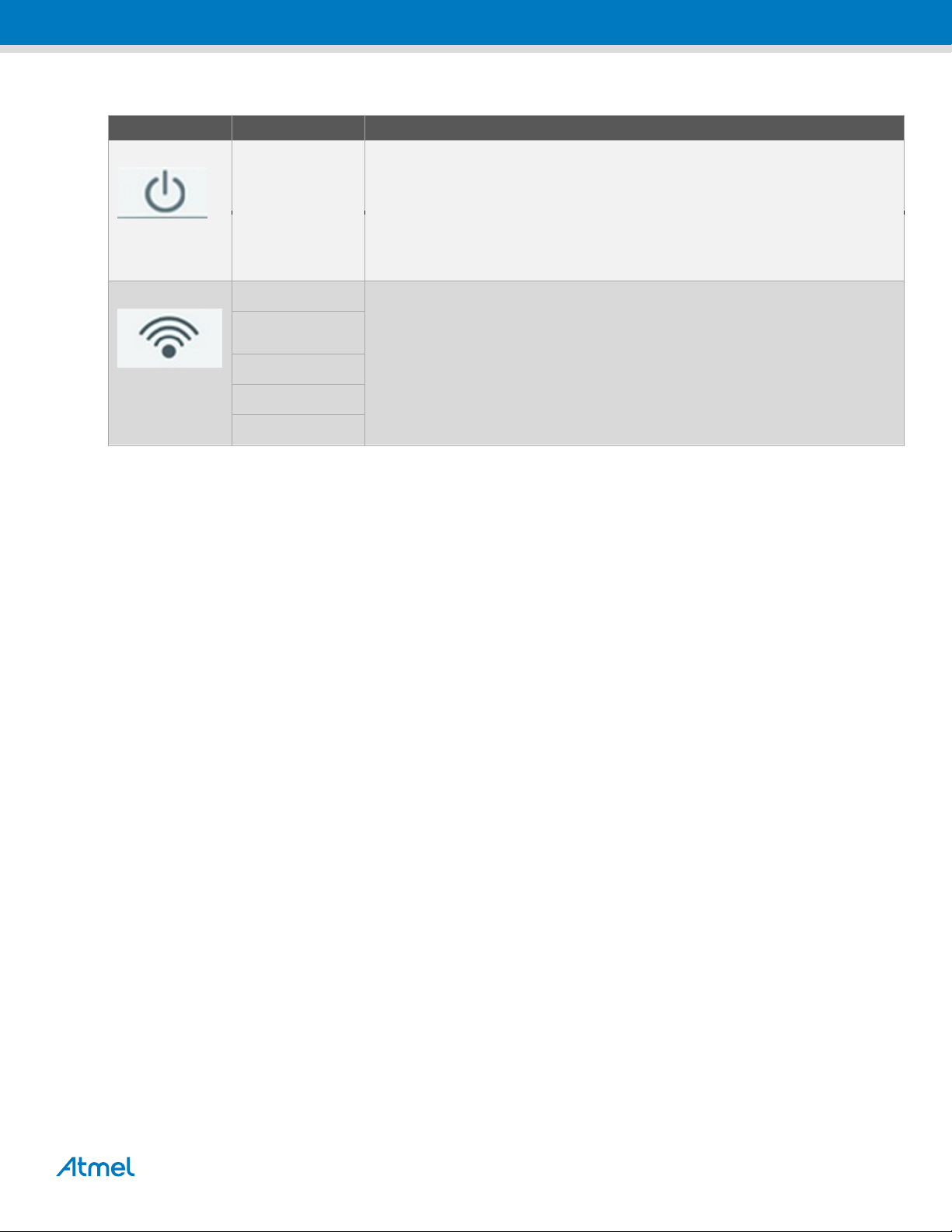
Component
Function
Power ON/OFF
GREEN
OFF
RED
ON
WiFi Status
Yellow blink
Plug in SoftAP mode, not connected (waiting for Phone to connect )
Yellow
Plug in SoftAP mode, connected to a phone (during this period, Phone App sends
SSID/password to plug)
Green blink
Plug in STA mode, connecting to home Access Point (AP)
Green
Plug in STA mode, connected to home AP, connection is good
Red
In error state
Table 1-2. LED Indication
PROJECT SPECIFICATION
Page 5
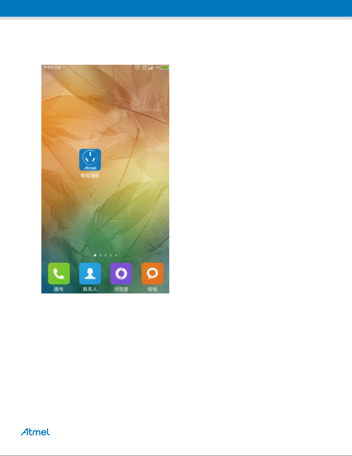
1.4 Build the connection between the Tablet or Smartphone and SmartPlug
1.4.1 Install the Atmel APK for SmartPlug on the Tablet or Smartphone based on the 4.2 or above version
Android System.
PROJECT SPECIFICATION
Page 6
1.4.2 Connect the Tablet or Smartphone to the used the Wi-Fi Router via Wi-Fi.
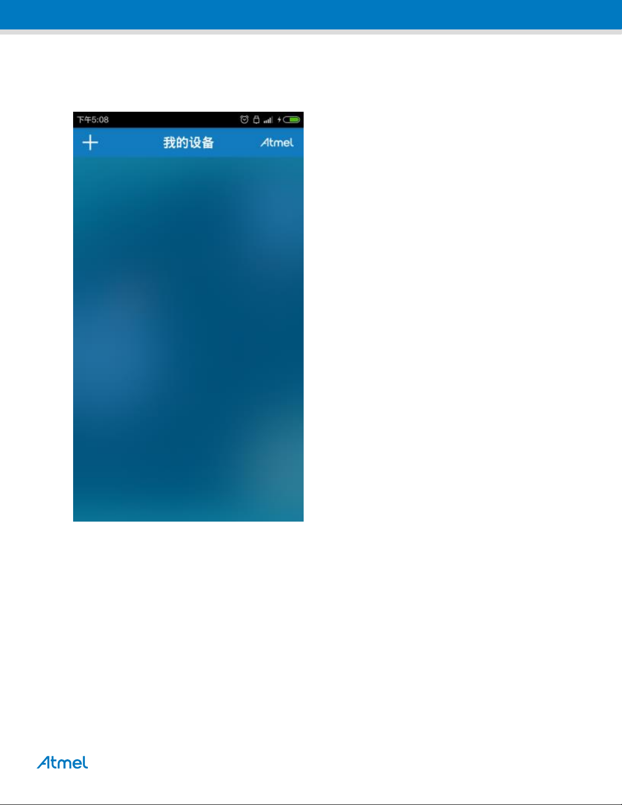
1.4.3 Power on the SmartPlug kit, touch the touch button more than 5s, the device run into the STA mode, and
the Green LED blink. Open the APP on the Tablet or Smartphone.
PROJECT SPECIFICATION
Page 7
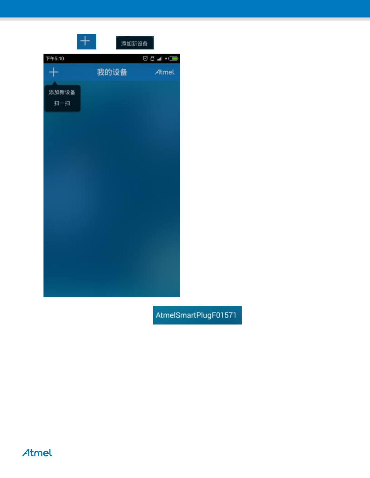
1.4.4 Touch the “ ” and “ ” to add the SmartPlug to the system
1.4.5 Find the new equipment and touch it “ ” to configure the connection.
PROJECT SPECIFICATION
Page 8

PROJECT SPECIFICATION
Page 9

PROJECT SPECIFICATION
Page 10

1.4.6 Touch the “ ” to choose the connected the used WLAN by Tablet or Smartphone,
and input the password of the WLAN, and then touch the “ ” to add the device to the
control system. If the add the device success, it will show
“ ” at the my device page.
PROJECT SPECIFICATION
Page 11
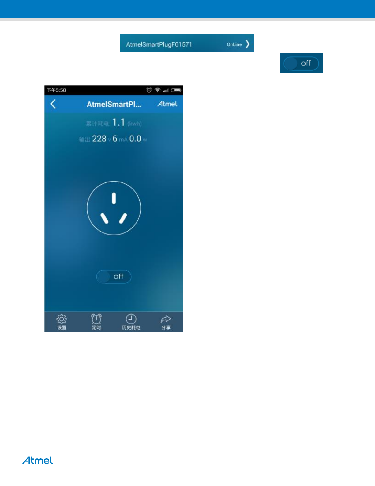
1.4.7 Touch the added device, “ ”, and run into the operating
interface to obtain the parameters of the SmartPlug, also can touch the ON/OFF “ ” icon to
control the SmartPlug ON/OFF.
PROJECT SPECIFICATION
Page 12

© 2012 Atmel Corporation. All rights reserved.
Atmel®, Atmel logo and combinations thereof, Enabling Unlimited Possibilities®, and others are registered trademarks or trademarks of Atmel Corporation or its
subsidiaries. Other terms and product names may be trademarks of others.
Disclaimer: The information in this document is provided in connection with Atmel products. No license, express or implied, by estoppel or otherwise, to any intellectual property right is granted by this
document or in connection with the sale of Atmel products. EXCEPT AS SET FORTH IN THE ATMEL TERMS AND CONDITIONS OF SALES LOCATED ON THE ATMEL WEBSITE, ATMEL ASSUMES
NO LIABILITY WHATSOEVER AND DISCLAIMS ANY EXPRESS, IMPLIED OR STATUTORY WARRANTY RELATING TO ITS PRODUCTS INCLUDING, BUT NOT LIMITED TO, THE IMPLIED
WARRANTY OF MERCHANTABILITY, FITNESS FOR A PARTICULAR PURPOSE, OR NON-INFRINGEMENT. IN NO EVENT SHALL ATMEL BE LIABLE FOR ANY DIRECT, INDIRECT,
CONSEQUENTIAL, PUNITIVE, SPECIAL OR INCIDENTAL DAMAGES (INCLUDING, WITHOUT LIMITATION, DAMAGES FOR LOSS AND PROFITS, BUSINESS INTERRUPTION, OR LOSS OF
INFORMATION) ARISING OUT OF THE USE OR INABILITY TO USE THIS DOCUMENT, EVEN IF ATMEL HAS BEEN ADVISED OF THE POSSIBILITY OF SUCH DAMAGES. Atmel makes no
representations or warranties with respect to the accuracy or completeness of the contents of this document and reserves the right to make changes to specifications and products descriptions at any time
without notice. Atmel does not make any commitment to update the information contained herein. Unless specifically provided otherwise, Atmel products are not suitable for, and shall not be used in,
automotive applications. Atmel products are not intended, authorized, or warranted for use as components in applications intended to support or sustain life.
FCC Statement
This device complies with Part 15 of the FCC rules. Operation is subject to the following two
conditions:
1) this device may not cause harmful interference, and
2) this device must accept any interference received, including interference that may cause undesired
operation.
Changes or modifications not expressly approved by the party responsible for compliance could void your
authority to operate the equipment.
NOTE: This equipment has been tested and found to comply with the limits for a Class B digital device,
pursuant to Part 15 of the FCC Rules. These limits are designed to provide reasonable protection against
harmful interference in a residential installation.
This equipment generates uses and can radiate radio frequency energy and, if not installed and used in
accordance with the instructions, may cause harmful interference to radio communications. However, there
is no guarantee that interference will not occur in a particular installation. If this equipment does cause
harmful interference to radio or television reception, which can be determined by turning the equipment off
and on, the user is encouraged to try to correct the interference by one or more of the following measures:
1) Reorient or relocate the receiving antenna.
2)Increase the separation between the equipment and receiver.
3)Connect the equipment into an outlet on a circuit different from that to which the receiver is
connected.
4)Consult the dealer or an experienced radio/TV technician for help.
The distance between user and products should be no less than 20cm
Atmel Corporation
1600 Technology Drive
San Jose, CA 95110
USA
Tel: (+1)(408) 441-0311
Fax: (+1)(408) 487-2600
www.atmel.com
Atmel Asia Limited
Unit 01-5 & 16, 19F
BEA Tower, Millennium City 5
418 Kwun Tong Road
Kwun Tong, Kowloon
HONG KONG
Tel: (+852) 2245-6100
Fax: (+852) 2722-1369
Atmel Munich GmbH
Business Campus
Parkring 4
D-85748 Garching b. Munich
GERMANY
Tel: (+49) 89-31970-0
Fax: (+49) 89-3194621
Atmel Japan G.K.
16F Shin-Osaki Kangyo Bldg.
1-6-4 Osaki, Shinagawa-ku
Tokyo 141-0032
JAPAN
Tel: (+81)(3) 6417-0300
Fax: (+81)(3) 6417-0370
 Loading...