

Microchip Technology SAM L10, SAM L1, SAM L11 Xplained Pro, SAM L10 Xplained Pro User Manual
Page 1

SAM L10/L11 Xplained Pro User Guide
Preface
The Microchip® SAM L10 and SAM L11 Xplained Pro evaluation kits are hardware platforms for
evaluating the SAM L10/L11 microcontrollers (MCUs). Each kit is supported by the Atmel Studio
integrated development platform, which provides an easy access to the features of the microcontroller.
The Xplained Pro MCU series evaluation kits include an on-board embedded debugger, hence external
tools are not required to program or debug the microcontroller. The Xplained Pro extension kit offers
additional peripherals to extend the features of the board and ease the development of custom designs.
© 2018 Microchip Technology Inc.
User Guide
DS70005359B-page 1
Page 2

Table of Contents
Preface............................................................................................................................ 1
1. Introduction................................................................................................................3
1.1. Features....................................................................................................................................... 3
1.2. Kit Overview................................................................................................................................. 3
2. Getting Started.......................................................................................................... 5
3. Xplained Pro.............................................................................................................. 6
3.1. Embedded Debugger................................................................................................................... 6
3.2. Xplained Pro Analog Module........................................................................................................7
3.3. Hardware Identification System....................................................................................................8
3.4. Power Sources............................................................................................................................. 9
3.5. Xplained Pro Headers and Connectors........................................................................................9
4. Hardware User Guide..............................................................................................12
4.1. Connectors................................................................................................................................. 12
4.2. Peripherals................................................................................................................................. 17
4.3. Embedded Debugger Implementation........................................................................................18
5. XAM Configuration.................................................................................................. 21
6. Identifying Product ID and Revision........................................................................ 23
7. Revision History.......................................................................................................24
The Microchip Web Site................................................................................................ 25
Customer Change Notification Service..........................................................................25
Customer Support......................................................................................................... 25
Microchip Devices Code Protection Feature................................................................. 25
Legal Notice...................................................................................................................26
Trademarks................................................................................................................... 26
Quality Management System Certified by DNV.............................................................27
Worldwide Sales and Service........................................................................................28
© 2018 Microchip Technology Inc.
User Guide
DS70005359B-page 2
Page 3

1. Introduction
1.1 Features
The following are key features of the board:
• ATSAML10E16A-AU/ATSAML11E16A-AU microcontrollers
• One mechanical reset button
• One mechanical programmable button
• One QTouch® button
• One user LED (yellow)
• 32.768 kHz crystal
• ATECC508A CryptoAuthentication™ IC
• Two Xplained Pro extension headers
• mikroBUS™ header
• X32 header
• Embedded debugger
– Auto ID for board identification in Atmel Studio
– One status LED (yellow)
– One board power LED (green)
– Symbolic debug of complex data types, including scope information
– Programming and debugging, including power measurements
– Data Gateway Interface: SPI, I2C, four GPIOs
– Virtual COM port (CDC)
• Embedded current measurement circuitry with Atmel Data Visualizer support for data visualization
• USB powered
Introduction
1.2 Kit Overview
The Microchip SAM L10 and SAM L11 Xplained Pro Evaluation kits are hardware platforms for the
evaluation of the Microchip SAM L10/L11 devices.
The Evaluation kit part numbers are as follows:
• SAM L10 Xplained Pro: DM320204
• SAM L11 Xplained Pro: DM320205
The kit offers a set of features that enables the user to get started with the microcontroller peripherals
immediately and to obtain an understanding of how to integrate the device in their required design.
© 2018 Microchip Technology Inc.
User Guide
DS70005359B-page 3
Page 4

Figure 1-1. SAM L10 Xplained Pro Evaluation Kit Overview
Introduction
© 2018 Microchip Technology Inc.
User Guide
DS70005359B-page 4
Page 5

2. Getting Started
Follow these steps to explore the Microchip Xplained Pro platform:
1. Download Atmel Studio.
2. Launch Atmel Studio.
3. Connect the debug USB port on the kit to the computer using a USB cable (Standard-A to Micro-B
or Micro-AB).
When the Xplained Pro MCU kit is connected to the computer for the first time, the operating system will
install the software driver. The driver file supports both the 32-bit and 64-bit versions of Microsoft
Windows®XP, Windows Vista®, Windows 7, Windows 8, and Windows 10.
When the Xplained Pro MCU board is powered, the power LED (green) will glow and Atmel Studio will
autodetect the specific Xplained Pro MCU and extension boards that are connected to it. Atmel Studio will
present relevant information, such as datasheets and kit documentation.
The SAM L10/L11 devices are programmed and debugged by the on-board embedded debugger,
therefore, no external programmer or debugger tool is required.
Getting Started
®
© 2018 Microchip Technology Inc.
User Guide
DS70005359B-page 5
Page 6

3. Xplained Pro
The Xplained Pro is an evaluation platform that provides the full Microchip microcontroller experience.
The platform consists of a series of Microcontrollers (MCUs) and extension boards. These are integrated
with Atmel Studio, which contains Advanced Software Framework (ASF) drivers, demo code, support
data streaming, and so on.
The Xplained Pro MCU boards support a wide range of Xplained Pro extension boards, and are
connected through a set of standardized headers and connectors. Each extension board has an
identification (ID) chip to uniquely identify which boards are connected to an Xplained Pro MCU board.
This information is used to present relevant user guides, application notes, data sheets, and example
code through Atmel Studio.
3.1 Embedded Debugger
The Xplained Pro contains the Microchip Embedded Debugger (EDBG) for on-board debugging. The
EDBG is a complex USB device with three interfaces, such as a debugger, virtual COM port, and a data
gateway interface (DGI). Together with Atmel Studio, the EDBG debugger interface can program and
debug the microcontroller. On the SAM L10/SAM L11 Xplained Pro, the SWD interface is connected
between the EDBG and the microcontroller.
Xplained Pro
The virtual COM Port is connected to a UART on the microcontroller and provides a straightforward way
to communicate with the target application through terminal software. It offers variable baud rate, parity,
and stop bit settings. Note that the settings on the microcontroller must match the settings given in the
terminal software.
Note: The virtual COM port in the EDBG requires the terminal software to set the data terminal ready
(DTR) signal to enable the UART pins connected to the microcontroller. If the DTR signal is not enabled,
the UART pins on the EDBG is kept in high-z (tristate), rendering the COM port unusable. The DTR signal
is set automatically by some terminal software, but it must be manually enabled in the terminal.
The DGI consists of several physical interfaces for communication with the host computer.
Communication over the interfaces is bidirectional. It can be used to send events and values from the
microcontroller or as a generic printf-style data channel. Traffic over the interfaces can be time stamped
on the EDBG for accurate tracing of events. Timestamping imposes an overhead that reduces maximum
throughput. The Atmel Data Visualizer Extension, installed with Atmel Studio, is used to send and receive
data through DGI.
The EDBG controls two LEDs on the SAM L10/SAM L11 Xplained Pro: a power LED and a status LED.
The following table provides how the LEDs are controlled in different operation modes.
Table 3-1. EDBG LED Control
Operation Mode Power LED Status LED
Normal Operation Power LED is lit when power is
applied to the board.
Activity indicator, LED flashes
when any communication
happens to the EDBG.
Bootloader Mode (idle) The power LED and the status LED blink simultaneously.
Bootloader Mode (firmware
upgrade)
© 2018 Microchip Technology Inc.
The power LED and the status LED blink in an alternating pattern.
User Guide
DS70005359B-page 6
Page 7

For further documentation on the EDBG, refer to the Microchip EDBG User Guide.
3.2 Xplained Pro Analog Module
3.2.1 Overview
The Xplained Pro Analog Module (XAM) extends the embedded debugger with high dynamic range
current measurement, and this enables the power profiling of the target system.
Figure 3-1. Xplained Pro Analog Module (XAM)
Xplained Pro
The XAM consists of these following key features:
• Calibration circuitry
• Voltage reference
• Analog frontend
– Shunt resistors with a range selection switch
– Pre-amplifier
– Two active filters with gain
• Control MCU
– Analog-to-Digital Converter (ADC)
– Signal processing
– Control/communication interface to the EDBG
The current measurement frontend is a high-side shunt measurement with a pre-amplifier, and a second
active filter stage with gain. The wide dynamic range is achieved by four measurement ranges which are
defined by two shunts, and the two parallel second stage active filters with gain.
3.2.2 EDBG Interface
The Xplained Pro Analog Module (XAM) is connected to the EDBG with the following interfaces:
© 2018 Microchip Technology Inc.
User Guide
DS70005359B-page 7
Page 8

• I2C: This is used to control and configure the XAM.
• SPI: Current measurement data is streamed to the EDBG through this interface. This is a one-way
data transfer channel from the XAM to the EDBG.
• SWD: The MCU in the XAM is programmed through SWD from the EDBG.
• GPIO: At least one GPIO, that is connected to the EDBG from the target MCU, is also connected to
the current measurement unit to enable the user to sync current measurements with their
application.
• Clock sync: Synchronization signal to synchronize ADC measurements with EDBG.
3.2.3 Sample Rate
The raw sampling rate of the Xplained Pro analog module (XAM) is up to 250 kHz and with the default
averaging configuration (average of 16 samples). The actual output of the XAM is 16.67 kSPS, and the
XAM output sample rate is not an integer fraction of the raw sampling.
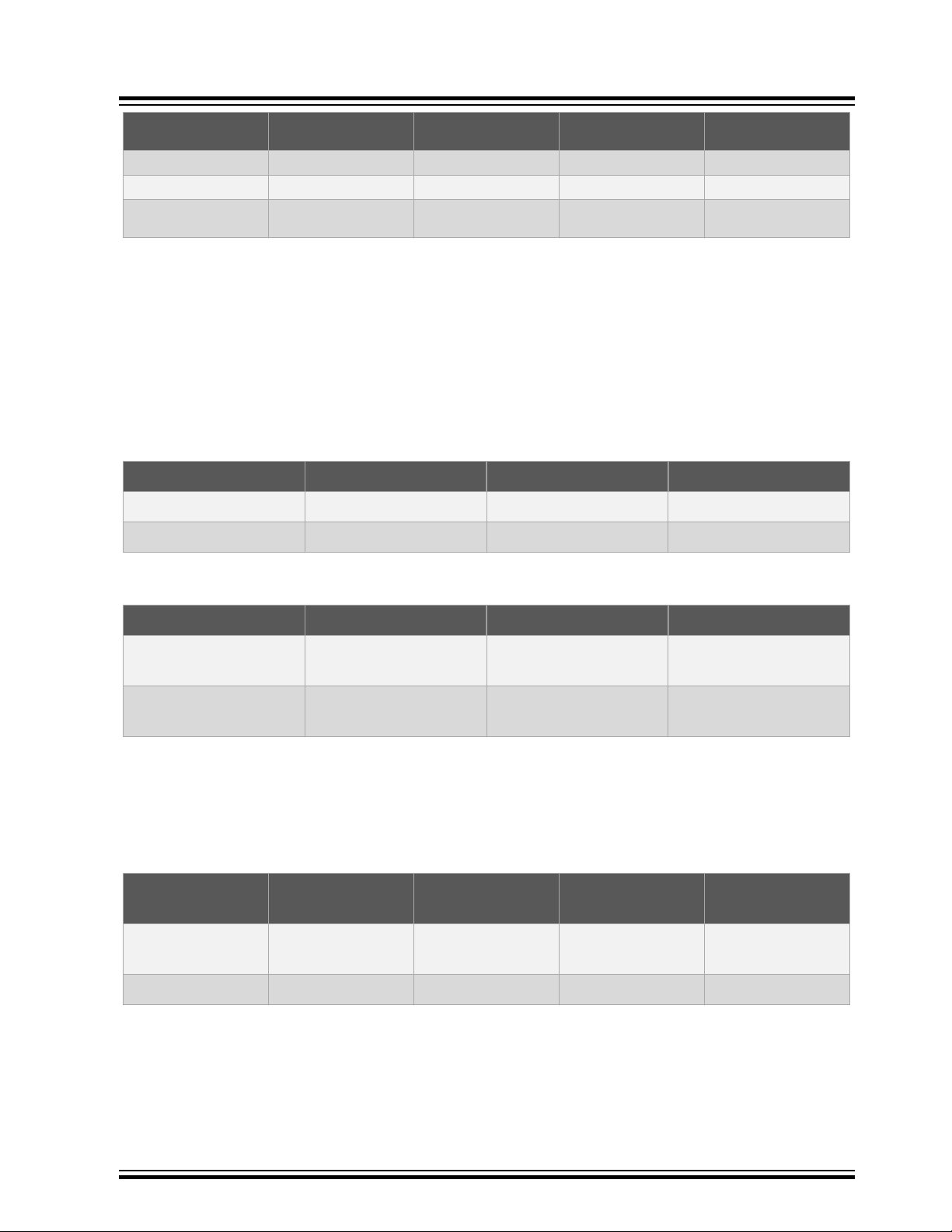
3.2.4 Measurement Ranges and Accuracy
The Xplained Pro analog module has four measurement ranges. These are defined by two shunt
resistors and two gain stages.
Table 3-2. Xplained Pro Analog Module Measurement Ranges and Accuracy
Xplained Pro
Measurement
Range
Range 1 Low-current shunt and
Range 2 Low-current shunt and
Range 3 High-current shunt and
Range 4 High current shunt and
The ranges are switched automatically by the XAM to achieve best measurement results and the current
active range is visualized in the Microchip Data Visualizer frontend tool. The maximum voltage drop over
the shunt resistor is 100 mV, and the XAM will switch the range automatically before this limit is reached.
Hardware Resolution Accuracy Comments
high-gain stage
low-gain stage
high-gain stage
low gain stage
3.3 Hardware Identification System
All Xplained Pro compatible extension boards have one Microchip ATSHA204 CryptoAuthentication
chip. This chip contains information that identifies the extension with its name and some extra data.
20 nA 1 LSB ±1% Below 1 µA the error will
increase. Typical error for 300
nA is 1 LSB ±10%
150 nA 1 LSB ±1% -
10 μA 1 LSB ±1% -
100 μA 1 LSB ±1% Above 100 mA the error will
increase to 1 LSB ±5% at 400
mA. Maximum current is 400
mA
™
When Xplained Pro extension is connected to the Xplained Pro MCU board, the information is read and
sent to Atmel Studio.
The Microchip Kits extension, installed with Atmel Studio, will give relevant information, code examples,
and links to relevant documents.
The following table provides the data fields stored in the ID chip with example content.
© 2018 Microchip Technology Inc.
User Guide
DS70005359B-page 8
Page 9

Table 3-3. Xplained Pro ID Chip Content
Data Field Data Type Example Content
Manufacturer ASCII string Atmel’\0’
Product Name ASCII string Segment LCD1 Xplained Pro’\0’
Product Revision ASCII string 02’\0’
Product Serial Number ASCII string 1774020200000010’\0’
Minimum Voltage [mV] uint16_t 3000
Maximum Voltage [mV] uint16_t 3600
Maximum Current [mA] uint16_t 30
3.4 Power Sources
The SAM L10/SAM L11 Xplained Pro kits can be powered by several power sources as listed in the
following table.
Xplained Pro
Table 3-4. Power Sources for SAM L10/SAM L11 Xplained Pro
Power Input Voltage Requirements Current Requirements Connector
External Power 4.3V to 5.5V . Recommended maximum is 2A due
Embedded
Debugger
The kit will automatically detect the available power sources and choose which one to use according to
the following priority:
• External power
• Embedded debugger USB
Note: External power is required when 500 mA from a USB connector is not sufficient to power the
board with possible extension boards.
4.4V to 5.25V (according to
USB specifications).
3.5 Xplained Pro Headers and Connectors
3.5.1 Xplained Pro Standard Extension Header
All Xplained Pro kits have many dual row, 20-pin, 100 mil extension headers. The Xplained Pro MCU
boards have male headers, while Xplained Pro extensions have their female counterparts. All pins are not
always connected, and the connected pins follow the defined pin-out descriptions given in the following
table.
to the input protection maximum
current specification.
500 mA (according to USB
specifications)
Marking
PWR
DEBUG USB
The extension headers can be used to connect a variety of Xplained Pro extensions to Xplained Pro MCU
boards, or to access the pins of the target MCU on Xplained Pro MCU boards directly.
© 2018 Microchip Technology Inc.
User Guide
DS70005359B-page 9
Page 10

Xplained Pro
Table 3-5. Xplained Pro Standard Extension Header
Pin Number Name Description
1 ID_EXTx Communication line to the ID chip on an extension board EXTx
2 GND Ground
3 ADC(+) Analog-to-Digital Converter (ADC) alternatively positive part of
differential ADC
4 ADC(-) ADC alternatively negative part of differential ADC
5 GPIO General purpose I/O
6 GPIO General purpose I/O
7 PWM(+) Pulse Width (PWM) alternatively positive part of differential PWM
8 PWM(-) PWM alternatively negative part of differential PWM
9 IRQ/GPIO Interrupt Request Line and/or general purpose I/O
10 SPI_SS_B/GPIO Slave Select for SPI and/or general purpose I/O
11 TWI_SDA Data line for I²C interface
12 TWI_SCL Clock line for I²C interface
13 UART_RX Receiver line of target device UART
14 UART_TX Transmitter line of target device UART
15 SPI_SS_A Slave Select for SPI. Should preferably be unique.
16 SPI_MOSI Master out slave in line of serial peripheral interface
17 SPI_MISO Master in slave out line of serial peripheral interface
18 SPI_SCK Clock for SPI. Always implemented, bus type.
19 GND Ground
20 VCC Power for extension board
3.5.2 Xplained Pro Power Header
The power header (PWR) can be used to connect external power to the SAM L10/SAM L11 Xplained Pro
kit. The kit will automatically detect and switch to any external power if supplied. The power header can
also be used as a supply for external peripherals or extension boards. Care must be taken not to exceed
the total current limitation of the on-board regulator when using the 3.3V pin.
Table 3-6. Xplained Pro Power Header (PWR)
Pin Number Pin Name Description Connector Marking
1 VCC_EXT_P5V0 External 5V input 5.0V IN
2 GND Ground GND
© 2018 Microchip Technology Inc.
User Guide
DS70005359B-page 10
Page 11

Xplained Pro
Pin Number Pin Name Description Connector Marking
3 VCC_MUX_P5V0 Unregulated 5V (output, derived from one of
the input sources)
4 VCC_TARGET_P3V3 Regulated 3.3V (output, used as main
power supply for the kit)
5.0V
VCC
© 2018 Microchip Technology Inc.
User Guide
DS70005359B-page 11
Page 12

4. Hardware User Guide
4.1 Connectors
The following sections describe the implementation of the different connectors and headers on the SAM
L10/SAM L11 Xplained Pro and their connections to the SAM L10/L11.
The tables below describe which signals are shared between the headers and on-board functionality.
The following figure shows available connectors and jumpers on the SAM L10/SAM L11 Xplained Pro.
Figure 4-1. Xplain Pro Connectors
Hardware User Guide
4.1.1 Xplained Pro Extension Headers
The SAM L10/SAM L11 Xplained Pro headers, EXT1 and EXT2, offer access to the I/O of the
microcontroller to expand the board by connecting extensions. These headers are based on the standard
extension header specified in the following table. The headers have a pitch of 2.54 mm.
© 2018 Microchip Technology Inc.
User Guide
DS70005359B-page 12
Page 13

Table 4-1. Extension Header EXT1
Hardware User Guide
EXT1 pin
1 [ID] - - - Communication line to the ID Chip on
2 [GND] GND - GND Ground
3 [ADC(+)] PA02 AIN0 PA02_ADC0 mikroBUS, X32
4 [ADC(-)] PA03 AIN1 / VREFA PA03_ADC1_VREF -
5 [GPIO] PA10 SERCOM2/PAD[2]/USART RTS PA10_GPIO1_S2_USART_RTS DGI GPIO, X32
6 [GPIO] PA11 SERCOM2/PAD[3]/USART CTS PA11_GPIO2_S2_USART_CTS DGI GPIO, X32
7 [PWM(+)] PA18 TC2/WO[0] PA18_PWM_TC2_0 mikroBUS
8 [PWM(-)] PA19 TC2/WO[1] PA19_PWM_TC2_1 -
9 [IRQ/GPIO] PA22 EXTINT[1] PA22_GPIO_IRQ_1 mikroBUS, X32
10 [SPI_SS_B/GPIO] PA23 GPIO/SERCOM0/PAD[1]/SPI SS PA23_GPIO_SS DGI GPIO
11 [TWI_SDA] PA16 SERCOM1/PAD[0]/I²C SDA PA16_S1_I2C_SDA EXT2, DGI I²C, mikroBUS, X32, I²C
12 [TWI_SCL] PA17 SERCOM1/PAD[1]/ I²C SCL PA17_S1_I2C_SCL EXT2, DGI I²C, mikroBUS, X32, I²C
13 [USART_RX] PA09 PA09_S2_UART_RX PA09_S2_UART_RX mikroBUS, X32
14 [USART_TX] PA08 PA08_S2_UART_TX PA08_S2_UART_TX mikroBUS, X32
15 [SPI_SS_A] PA05 PA05_S0_SPI_SS PA05_S0_SPI_SS mikroBUS, X32
16 [SPI_MOSI] PA14 PA14_S0_SPI_MOSI PA14_S0_SPI_MOSI EXT2, DGI SPI, mikroBUS, X32
17 [SPI_MISO]] PA04 PA04_S0_SPI_MISO PA04_S0_SPI_MISO EXT2, DGI SPI, mikroBUS, X32
18 [SPI_SCK] PA15 PA15_S0_SPI_SCK PA15_S0_SPI_SCK EXT2, DGI SPI, mikroBUS, X32
19 [GND] GND - GND Ground
20 [VCC] - - VCC_TARGET_P3V3 Power for extension Board
SAM L10/SAM
L11 pin
Functions Schematics Net Name Shared Functionality
the extension board
Pull-up, ECC508
Pull-up, ECC508
Table 4-2. Extension Header EXT2
EXT2 pin
1 [ID] - - - Communication line to the ID Chip on the
2 [GND] GND - GND Ground
3 [ADC(+)] - - Not Connected -
4 [ADC(-)] - - Not Connected -
5 [GPIO1] - - Not Connected -
6 [GPIO2] - - Not Connected -
7 [PWM(+)] - - Not Connected -
8 [PWM(-)] - - Not Connected -
9 [IRQ/GPIO] - - Not Connected -
10 [SPI_SS_B/GPIO] PA27 GPIO/SPI SS PA27_GPIO_SS DGI GPIO, SW0
11 [TWI_SDA] PA16 SERCOM1/PAD[0]/I²C SDA PA16_S1_I2C_SDA EXT1, DGI I²C, mikroBUS, X32, I²C Pull-up,
12 [TWI_SCL] PA17 SERCOM1/PAD[1]/ I²C SCL PA17_S1_I2C_SCL EXT1, DGI I²C, mikroBUS, X32, I²C Pull-up,
SAM L10/SAM L11
pin
Functions Schematics Net Name Shared Functionality
extension board
ECC508
ECC508
© 2018 Microchip Technology Inc.
User Guide
DS70005359B-page 13
Page 14

Hardware User Guide
EXT2 pin SAM L10/SAM L11
pin
13 [USART_RX] PA25 SERCOM0/PAD[3]/UART RX PA25_UART_RX mikroBUS, X32
14 [USART_TX] PA24 SERCOM0/PAD[2]/UART TX PA24_UART_TX mikroBUS, X32
15 [SPI_SS_A] PA06 GPIO/SPI SS PA06_SPI_SS mikroBUS, X32, QT BTN1
16 [SPI_MOSI] PA14 SERCOM0/PAD[2]/SPI MOSI PA14_S0_SPI_MOSI EXT1, DGI SPI, mikroBUS, X32
17 [SPI_MISO] PA04 SERCOM0/PAD[0]/SPI MISO PA04_S0_SPI_MISO EXT1, DGI SPI, mikroBUS, X32
18 [SPI_SCK] PA15 SERCOM0/PAD[3]/SPI SCK PA15_S0_SPI_SCK EXT1, DGI SPI, mikroBUS, X32
19 [GND] GND - GND Ground
20 [VCC] - - VCC_TARGET_P3V3 Power for extension Board
4.1.2 mikroBUS™ Header
The mikroBUS socket is comprised of a pair of 1×8 female headers with a proprietary pin configuration
and silkscreen markings. The pinout (always laid out in the same order) consists of three groups of
communication pins (SPI, UART and I2C), five additional pins (PWM, interrupt, analog input, reset and
chip select), and two power groups (+3.3V and 5V). The figure below illustrates the mikroBUS socket,
and the table below provides mikroBUS header details.
Figure 4-2. mikroBUS Socket
Functions Schematics Net Name Shared Functionality
Table 4-3. mikroBUS Header
mikroBUS pin
[AN] PA02 AIN0 PA02_ADC0 EXT1, X32
[RST] /RESET Reset TARGET_MCU_RESET EDBG SWD, X32, User BUS
[CS] PA05 SERCOM0/PAD[1]/SPI SS PA05_S0_SPI_SS EXT1, X32
[SCK] PA15 SERCOM0/PAD[3] /SPI SCK PA15_S0_SPI_SCK EXT1, EXT2, DGI SPI, X32
[MISO] PA04 SERCOM0/PAD[0]/SPI MISO PA04_S0_SPI_MISO EXT1, EXT2, DGI SPI, X32
[MOSI] PA14 SERCOM0/PAD[2]/SPI MOSI PA14_S0_SPI_MOSI EXT1, EXT2, DGI SPI, X32
[+3.3V] - - VCC_TARGET_P3V3 -
[GND] GND - GND Ground
[PWM] PA18 TC2/ WO[0] PA18_PWM_TC2_0 EXT1
© 2018 Microchip Technology Inc.
SAML10/SAML11 pin Function Schematics Net Name Shared Functionality
User Guide
DS70005359B-page 14
Page 15

mikroBUS pin SAML10/SAML11 pin Function Schematics Net Name Shared Functionality
[INT] PA22 EXTINT[1] PA22_GPIO_IRQ_1 EXT1, X32
[RX] PA09 SERCOM2/PAD[1]/ UART RX PA09_S2_UART_RX EXT1, X32
[TX] PA08 SERCOM2/PAD[0]/ UART TX PA08_S2_UART_TX EXT1, X32
[SCL] PA17 SERCOM1/PAD[1]/ I²C SCL PA17_S1_I2C_SCL EXT1, EXT2, DGI I²C, X32, I²C Pull-up, ECC508
[SDA] PA16 SERCOM1/PAD[0]/I²C SDA PA16_S1_I2C_SDA EXT1, EXT2, DGI I²C, X32, I²C Pull-up, ECC508
[+5V] - - VCC_P5V0 -
[GND] GND - GND Ground
4.1.3 X32 Header
The X32 header is populated on some of the PIC32 development kits, and enables the customer to plug
in an extension board, such as a Microchip Bluetooth or the AC320032-3 BM 64 Bluetooth Radio
daughter board, which is available for download at http://www.microchip.com/Developmenttools/
ProductDetails.aspx?PartNO=AC320032-3.
The X32 header is composed of a 20-pin connector and a 12-pin connector, which are described in the
following tables:
Table 4-4. 20-pin Connector
Hardware User Guide
X32BUS pin SAML10/SAML11 pin Function Schematics Net Name Shared Functionality
1 [GND] Ground Ground - -
2 [GND] Ground Ground - -
3 [USART_RX] PA09 USART RX PA09_S2_UART_RX EXT1, mikroBUS
4 [USART_CTS] PA11 USART CTS PA11_GPIO2_S2_USART_CTS EXT1, DGI GPIO
5 [USART_TX] PA08 USART TX PA08_S2_UART_TX EXT1, mikroBUS
6 [USART_RTS] PA10 USART RTS PA10_GPIO1_S2_USART_RTS EXT1, DGI GPIO
7 [I2C_SCL] PA17 I²C SCL PA17_S1_I2C_SCL EXT1, EXT2, DGI I²C, mikroBUS, I²C Pull-up,
8 [STBY/RST_B] RESET RESET TARGET_MCU_RESET -
9 [I2C_SDA] PA16 I²C SDA PA16_S1_I2C_SDA EXT1, EXT2, DGI I²C, mikroBUS, I²C Pull-up,
10 [DMM/I2S_WS] PA05 DMM / I2S WS PA05_S0_SPI_SS EXT1, mikroBUS
11 [I2S_DIN] PA14 I²S DIN PA14_S0_SPI_MOSI EXT1, EXT2, mikroBUS, DGI SPI, XIN
12 [I2S_CK] PA15 I²S CK PA15_S0_SPI_SCK EXT1, EXT2, mikroBUS, DGI SPI, XOUT
13 [I2S_DOUT] PA04 I²S DOUT PA04_S0_SPI_MISO EXT1, EXT2, mikroBUS, DGI SPI
14 [CLK_AUDIO] PA22 CLK Audio PA22_GPIO_IRQ_1 EXT1, mikroBUS
15 [GND] GND Ground GND -
16 [GND] GND Ground GND -
17 Not Connected - - - -
18 [+3.3V] - - VCC_TARGET_P3V3 -
19 Not Connected - - - -
20 [+5V] - - VCC_P5V0 -
ECC508
ECC508
© 2018 Microchip Technology Inc.
User Guide
DS70005359B-page 15
Page 16

Table 4-5. 12-pin Connector
CAUTION
X32BUS pin SAML10/SAML11 pin Function Schematics Net Name Shared Functionality
1 Not Connected - - - -
2 [ANALOG_POT] PA02 Analog Pot PA02_ADC0 EXT1, mikroBUS
3 Not Connected - - - -
4 Not Connected - - - -
5 Not Connected - - - -
6 Not Connected - - - -
7 Not Connected - - - -
8 Not Connected - - - -
9 Not Connected - - - -
10 Not Connected - - - -
11 [GND] Ground - - Ground
12 [GND] Ground - - Ground
4.1.4 Current Measurement Header
An angled 1x2, 100 mil pin-header marked with the MCU current measurement is located at the upper
edge of the Xplained Pro. All power to the SAM L10/L11 is routed through this header. To measure the
power consumption of the device, remove the jumper and replace it with an ammeter.
Hardware User Guide
Table 4-6.
Current Measurement Header Pin Function
1 [VCC_MCU] VCC_MCU_P3V3
2 [VCC_TARGET] VCC_TARGET_P3V3
Removing the jumper from the pin-header while the kit is powered may cause the SAM L10/L11
to be powered through its I/O pins. This may cause permanent damage to the device.
4.1.5 Cortex Debug Connector
The Xplained Pro has a 10-pin, 50-mil Cortex® Debug Connector that can be used to attach external
debuggers to the SAM L10/L11.
Table 4-7.
Cortex Debug Connector
pin
1 [VCC] - - VCC_TARGET_P3V3 -
2 [SWDIO/TMS] PA31 SW Data In/Out SWDIO Serial Wire debug
3 [GND] GND Ground GND -
4 [SWCLK/TCK] PA30 SW Clock SWCLK Serial Wire debug
5 [GND] GND Ground GND -
6 [SWO/TDO] Not connected - - -
7 [KEY] Not connected - - -
SAML10/SAML11 pin Function Schematics Net Name Shared Functionality
© 2018 Microchip Technology Inc.
User Guide
DS70005359B-page 16
Page 17
Hardware User Guide
Cortex Debug Connector
pin
8 [NC/TDI] Not connected - - -
9 [GNDDetect] GND Ground GND -
10 [nRESET] /RESET Reset TARGET_MCU_RESET Serial Wire debug, User
4.2 Peripherals
4.2.1 Crystals
The Xplained Pro kit contains one mounted 32.768 kHz crystal and a footprint for higher frequency
crystals, which can be used as clock sources for SAM L10/L11. The footprint for the 32.768 kHz crystal is
based on the Kyocera ST3215SB series.
• 32.768 kHz Crystal connection details are given in the following table.
Table 4-8. 32 KHz Crystal Connection
SAML10/SAML11 pin Function Schematics Net Name Shared Functionality
PA00 XIN32 XIN32 -
PA01 XOUT32 XOUT32 -
• Higher Frequency crystal footprint details are provided in the following table.
Table 4-9. Main Crystal Connection
SAML10/SAML11 pin Function Schematics Net Name Shared Functionality
reset
SAML10/SAML11 pin Function Schematics Net Name Shared Functionality
PA14 XIN XIN EXT1, EXT2, DGI SPI,
PA15 XOUT XOUT EXT1, EXT2, DGI SPI,
4.2.2 Mechanical Buttons
The Xplained Pro contains two mechanical buttons. One button is the Reset button connected to the SAM
L10/L11 reset line, and the other is a generic user configurable button. When a button is pressed it will
drive the I/O line to GND.
Table 4-10. Mechanical Buttons Connections
SAML10/SAML11
pin
/RESET Reset RESET TARGET_MCU_R
PA27 GPIO SW0 USER_BUTTON DGI GPIO, EXT2
4.2.3 LED
There is one yellow LED available on the Xplained Pro board that can be turned on and off. The LED can
be activated by driving the connected I/O line to GND.
Function Silkscreen Text Schematics Net
Name
ESET
mikroBUS, X32
mikroBUS, X32
Shared
Functionality
-
© 2018 Microchip Technology Inc.
User Guide
DS70005359B-page 17
Page 18

Table 4-11. LED Connection
Hardware User Guide
SAML10/SAML11
pin
PA07 Yellow LED LED0 USER_LED DGI SPI
4.2.4 QTouch Button
One self-capacitance button is available on the Xplained Pro board that can be used as the I/O. The
QTouch button is intended to be driven by the built-in Peripheral Touch Controller (PTC) of the device. A
resistor is added on the board to easily disconnect the on-board touch buttons from the extension header
as the I/O lines are shared between the two.
Note: To get started with QTouch refer to the Atmel QTouch® Library and Atmel QTouch® Composer.
Table 4-12. Qtouch Button Connection
SAML10/SAML11
pin
PA06 Self-capacitance
Function Silkscreen Text Schematics Net
Function Silkscreen Text Schematics Net
QT BTN1 USER_QTOUCH EXT2
QTouch button
4.3 Embedded Debugger Implementation
The Xplained Pro contains an Embedded Debugger (EDBG) that can be used to program and debug the
SAM L10/L11 using Serial Wire Debug (SWD). The Embedded Debugger also includes a virtual CPM port
interface over UART, an Atmel Data Gateway Interface over SPI, TWI (I²C), and four of the SAM L10/L11
GPIOs.
Name
Name
Shared
Functionality
Shared
Functionality
Atmel Studio can be used as a front end for the Embedded Debugger.
4.3.1 Serial Wire Debug
The Serial Wire Debug (SWD) uses two pins to communicate with the target. For further information on
how to use the programming and debugging capabilities of the EDBG, refer to the Embedded Debugger
User Guide.
Table 4-13. Serial Wire Debug Connection
SAML10/SAML11 pin Function Schematics Net Name Shared Functionality
/RESET Reset TARGET_MCU_RESET mikroBUS, X32BUS,
PA30 Serial Wire Clock SWCLK Cortex debug Connector
PA31 Serial Wire Data IN/OUT SWDIO Cortex debug Connector
4.3.2 Virtual COM Port
The Embedded Debugger acts as a virtual COM port gateway by using one of the SAM L10/L11 UARTs.
For further information on how to use the virtual COM port, refer to the Embedded Debugger User Guide.
USER Reset (RESET)
© 2018 Microchip Technology Inc.
User Guide
DS70005359B-page 18
Page 19

Hardware User Guide
Table 4-14. Virtual COM Port Connection
SAML10/SAML11 pin Function Schematics Net Name Shared Functionality
PA25 SERCOM0/PAD[3]/
UART RX
PA24 SERCOM0/PAD[2]/
UART TX
4.3.3 Atmel Data Gateway Interface
The Embedded Debugger features a Microchip Data Gateway Interface (DGI) by using either a SPI or
I²C. The DGI can be used to send many data from the SAM L10/L11 to the host PC. For further
information on how to use the DGI interface, refer to the Data Gateway Interface User’s Guide and the
EDBG User Guide.
4.3.3.1 DGI Interface Connections When Using SPI
SAML10/SAML11
pin
PA07 GPIO / SS PA07_LED_PWM_TC0 LED0
PA14 SERCOM0/PAD[2]/ SPI
MOSI
PA04 SERCOM0/PAD[0]/ SPI
MISO
PA15 SERCOM0/PAD[3] /SPI
SCK
Function Schematics Net Name Shared Functionality
PA25_UART_RX EXT2
PA24_UART_TX EXT2
PA14_S0_SPI_MOSI EXT1, EXT2, mikroBUS, X32
PA04_S0_SPI_MISO EXT1, EXT2, mikroBUS, X32
PA15_S0_SPI_SCK EXT1, EXT2, mikroBUS, X32
4.3.3.2 DGI Interface When Using I2C
SAML10/SAML11 pin Function Schematics Net Name Shared Functionality
PA16 DGI TWI SDA PA16_S1_I2C_SDA EXT1, EXT2, mikroBUS,
PA17 DGI TWI SCL PA17_S1_I2C_SCL EXT1, EXT2, mikroBUS,
Four GPIO lines are connected to the Embedded Debugger. The EDBG can monitor these lines and time
stamp the pin value changes. This makes it possible to accurately time stamp events in the application
code.
X32, I²C Pull-up,
ECC508
X32, I²C Pull-up,
ECC508
© 2018 Microchip Technology Inc.
User Guide
DS70005359B-page 19
Page 20

4.3.3.3 GPIO Lines Connected to The EDBG
SAML10/SAML11 pin Function Schematics Net Name Shared Functionality
Hardware User Guide
PA10 DGI_GPIO0 PA10_GPIO1_S2_USA
RT_RTS
PA11 DGI_GPIO1 PA11_GPIO2_S2_USAR
T_CTS
PA23 DGI_GPIO2 PA23_GPIO_SS EXT1
PA27 DGI_GPIO3 PA27_GPIO_SS EXT2, SW0 user button
4.3.4 Trusted and Secure Authentication Device: ATECC508A
The ATECC508A is a secure element from the Microchip CryptoAuthentication portfolio with advanced
Elliptic Curve Cryptography (ECC) capabilities.
With ECDH and ECDSA built in, this device is ideal for the rapidly growing IoT market by easily supplying
the full range of security features, such as confidentiality, data integrity, and authentication to systems
with MCU or MPUs running encryption and decryption algorithms (i.e., AES). Similar to all Microchip
CryptoAuthentication products, the new ATECC508A employs ultra-secure hardware-based cryptographic
key storage and cryptographic counter measures which are robust than software-based key storage.
For additional information, refer to the ATECC508A document which is available for download at https://
www.microchip.com/wwwproducts/en/ATECC508A.
The connection between SAM L10/L11 and the ATECC508A requires only two I2C wires that are
summarized in the following table:
EXT1, X32
EXT1, X32
Table 4-15. ATECC508A Connections
SAML10/L11 pin Function Schematics Net Name Shared Functionality
PA16 I2C_SDA PA16_S1_I2C_SDA EXT1, EXT2, DGI I²C,
mikroBUS, X32, I2C pullup
PA17 I2C_SCL PA17_S1_I2C_SCL EXT1, EXT2, DGI I²C,
mikroBUS, X32, I2C pullup
© 2018 Microchip Technology Inc.
User Guide
DS70005359B-page 20
Page 21

5. XAM Configuration
On the SAM L10/SAM L11 Xplained Pro, the MCU and the MCU peripherals (for example, extensions)
are powered by its own regulator as shown in the following figure. All other parts of the board, specifically
the embedded debugger and accompanying Xplained Pro Analog Module (XAM), are powered from a
separate regulator. The current to the MCU and peripherals can be measured by connecting them to the
XAM output through the jumper settings.
Figure 5-1. XAM
XAM Configuration
On the Xplained Pro, the XAM can be used in the following four configurations:
• No current measurement or external MCU current measurement: The XAM is bypassed and
the MCU and peripherals are supplied by the regulator. Set both the jumpers in the BYPASS
position. In this configuration, it is also possible to connect external measurement tools on the
Xplained Pro MCU power measurement header to measure MCU current directly instead of using
the XAM.
• MCU current measurement: The XAM measures only the MCU current while the peripherals are
supplied by the regulator. For this configuration, place the jumper for the I/O (peripherals) into the
BYPASS position and the MCU into the MEASURE position.
• Peripherals measurement: The XAM measures only the current of the peripherals while the MCU
is supplied by the regulator. For this configuration place the jumper for MCU into the BYPASS
position and the I/O jumper into the MEASURE position.
© 2018 Microchip Technology Inc.
User Guide
DS70005359B-page 21
Page 22

XAM Configuration
• MCU and peripherals measurement: In this configuration both the MCU and the peripherals are
measured by the XAM. Place both the jumpers on I/O and MCU headers in the MEASURE position.
© 2018 Microchip Technology Inc.
User Guide
DS70005359B-page 22
Page 23

6. Identifying Product ID and Revision
The revision and product identifier of Xplained Pro boards can be found in two ways: either through Atmel
Studio or by looking at the sticker on the bottom of the PCB. By connecting an Xplained Pro MCU board
to a computer with Atmel Studio running, an information window will pop up. The first six digits of the
serial number, which is listed under kit details, contain the product identifier and revision. Information
about connected Xplained Pro extension boards will also appear in the Atmel Kit's window. The same
information can be found on the sticker on the bottom side of the PCB. Most kits will print the identifier
and revision in plain text as A09-nnnn\rr, where nnnn is the identifier and rr is the revision. Boards with
limited space have a sticker with only a QR-code, which contains a serial number string. The serial
number string has the following format:
"nnnnrrssssssssss"
n = product identifier
r = revision
s = serial number
Identifying Product ID and Revision
© 2018 Microchip Technology Inc.
User Guide
DS70005359B-page 23
Page 24

7. Revision History
Revision B
June, 2018
Removed errata section.
Revision A
May, 2018
Initial version of the document.
Revision History
© 2018 Microchip Technology Inc.
User Guide
DS70005359B-page 24
Page 25

The Microchip Web Site
Microchip provides online support via our web site at http://www.microchip.com/. This web site is used as
a means to make files and information easily available to customers. Accessible by using your favorite
Internet browser, the web site contains the following information:
• Product Support – Data sheets and errata, application notes and sample programs, design
resources, user’s guides and hardware support documents, latest software releases and archived
software
• General Technical Support – Frequently Asked Questions (FAQ), technical support requests,
online discussion groups, Microchip consultant program member listing
• Business of Microchip – Product selector and ordering guides, latest Microchip press releases,
listing of seminars and events, listings of Microchip sales offices, distributors and factory
representatives
Customer Change Notification Service
Microchip’s customer notification service helps keep customers current on Microchip products.
Subscribers will receive e-mail notification whenever there are changes, updates, revisions or errata
related to a specified product family or development tool of interest.
To register, access the Microchip web site at http://www.microchip.com/. Under “Support”, click on
“Customer Change Notification” and follow the registration instructions.
Customer Support
Users of Microchip products can receive assistance through several channels:
• Distributor or Representative
• Local Sales Office
• Field Application Engineer (FAE)
• Technical Support
Customers should contact their distributor, representative or Field Application Engineer (FAE) for support.
Local sales offices are also available to help customers. A listing of sales offices and locations is included
in the back of this document.
Technical support is available through the web site at: http://www.microchip.com/support
Microchip Devices Code Protection Feature
Note the following details of the code protection feature on Microchip devices:
• Microchip products meet the specification contained in their particular Microchip Data Sheet.
• Microchip believes that its family of products is one of the most secure families of its kind on the
market today, when used in the intended manner and under normal conditions.
• There are dishonest and possibly illegal methods used to breach the code protection feature. All of
these methods, to our knowledge, require using the Microchip products in a manner outside the
operating specifications contained in Microchip’s Data Sheets. Most likely, the person doing so is
engaged in theft of intellectual property.
• Microchip is willing to work with the customer who is concerned about the integrity of their code.
© 2018 Microchip Technology Inc.
User Guide
DS70005359B-page 25
Page 26

• Neither Microchip nor any other semiconductor manufacturer can guarantee the security of their
code. Code protection does not mean that we are guaranteeing the product as “unbreakable.”
Code protection is constantly evolving. We at Microchip are committed to continuously improving the
code protection features of our products. Attempts to break Microchip’s code protection feature may be a
violation of the Digital Millennium Copyright Act. If such acts allow unauthorized access to your software
or other copyrighted work, you may have a right to sue for relief under that Act.
Legal Notice
Information contained in this publication regarding device applications and the like is provided only for
your convenience and may be superseded by updates. It is your responsibility to ensure that your
application meets with your specifications. MICROCHIP MAKES NO REPRESENTATIONS OR
WARRANTIES OF ANY KIND WHETHER EXPRESS OR IMPLIED, WRITTEN OR ORAL, STATUTORY
OR OTHERWISE, RELATED TO THE INFORMATION, INCLUDING BUT NOT LIMITED TO ITS
CONDITION, QUALITY, PERFORMANCE, MERCHANTABILITY OR FITNESS FOR PURPOSE.
Microchip disclaims all liability arising from this information and its use. Use of Microchip devices in life
support and/or safety applications is entirely at the buyer’s risk, and the buyer agrees to defend,
indemnify and hold harmless Microchip from any and all damages, claims, suits, or expenses resulting
from such use. No licenses are conveyed, implicitly or otherwise, under any Microchip intellectual
property rights unless otherwise stated.
Trademarks
The Microchip name and logo, the Microchip logo, AnyRate, AVR, AVR logo, AVR Freaks, BeaconThings,
BitCloud, CryptoMemory, CryptoRF, dsPIC, FlashFlex, flexPWR, Heldo, JukeBlox, KeeLoq, KeeLoq logo,
Kleer, LANCheck, LINK MD, maXStylus, maXTouch, MediaLB, megaAVR, MOST, MOST logo, MPLAB,
OptoLyzer, PIC, picoPower, PICSTART, PIC32 logo, Prochip Designer, QTouch, RightTouch, SAM-BA,
SpyNIC, SST, SST Logo, SuperFlash, tinyAVR, UNI/O, and XMEGA are registered trademarks of
Microchip Technology Incorporated in the U.S.A. and other countries.
ClockWorks, The Embedded Control Solutions Company, EtherSynch, Hyper Speed Control, HyperLight
Load, IntelliMOS, mTouch, Precision Edge, and Quiet-Wire are registered trademarks of Microchip
Technology Incorporated in the U.S.A.
Adjacent Key Suppression, AKS, Analog-for-the-Digital Age, Any Capacitor, AnyIn, AnyOut, BodyCom,
chipKIT, chipKIT logo, CodeGuard, CryptoAuthentication, CryptoCompanion, CryptoController,
dsPICDEM, dsPICDEM.net, Dynamic Average Matching, DAM, ECAN, EtherGREEN, In-Circuit Serial
Programming, ICSP, Inter-Chip Connectivity, JitterBlocker, KleerNet, KleerNet logo, Mindi, MiWi,
motorBench, MPASM, MPF, MPLAB Certified logo, MPLIB, MPLINK, MultiTRAK, NetDetach, Omniscient
Code Generation, PICDEM, PICDEM.net, PICkit, PICtail, PureSilicon, QMatrix, RightTouch logo, REAL
ICE, Ripple Blocker, SAM-ICE, Serial Quad I/O, SMART-I.S., SQI, SuperSwitcher, SuperSwitcher II, Total
Endurance, TSHARC, USBCheck, VariSense, ViewSpan, WiperLock, Wireless DNA, and ZENA are
trademarks of Microchip Technology Incorporated in the U.S.A. and other countries.
SQTP is a service mark of Microchip Technology Incorporated in the U.S.A.
Silicon Storage Technology is a registered trademark of Microchip Technology Inc. in other countries.
GestIC is a registered trademark of Microchip Technology Germany II GmbH & Co. KG, a subsidiary of
Microchip Technology Inc., in other countries.
All other trademarks mentioned herein are property of their respective companies.
© 2018 Microchip Technology Inc.
User Guide
DS70005359B-page 26
Page 27

©
2018, Microchip Technology Incorporated, Printed in the U.S.A., All Rights Reserved.
ISBN: 978-1-5224-3258-6
Quality Management System Certified by DNV
ISO/TS 16949
Microchip received ISO/TS-16949:2009 certification for its worldwide headquarters, design and wafer
fabrication facilities in Chandler and Tempe, Arizona; Gresham, Oregon and design centers in California
and India. The Company’s quality system processes and procedures are for its PIC® MCUs and dsPIC
DSCs, KEELOQ® code hopping devices, Serial EEPROMs, microperipherals, nonvolatile memory and
analog products. In addition, Microchip’s quality system for the design and manufacture of development
systems is ISO 9001:2000 certified.
®
© 2018 Microchip Technology Inc.
User Guide
DS70005359B-page 27
Page 28

Worldwide Sales and Service
AMERICAS ASIA/PACIFIC ASIA/PACIFIC EUROPE
Corporate Office
2355 West Chandler Blvd.
Chandler, AZ 85224-6199
Tel: 480-792-7200
Fax: 480-792-7277
Technical Support:
http://www.microchip.com/
support
Web Address:
www.microchip.com
Atlanta
Duluth, GA
Tel: 678-957-9614
Fax: 678-957-1455
Austin, TX
Tel: 512-257-3370
Boston
Westborough, MA
Tel: 774-760-0087
Fax: 774-760-0088
Chicago
Itasca, IL
Tel: 630-285-0071
Fax: 630-285-0075
Dallas
Addison, TX
Tel: 972-818-7423
Fax: 972-818-2924
Detroit
Novi, MI
Tel: 248-848-4000
Houston, TX
Tel: 281-894-5983
Indianapolis
Noblesville, IN
Tel: 317-773-8323
Fax: 317-773-5453
Tel: 317-536-2380
Los Angeles
Mission Viejo, CA
Tel: 949-462-9523
Fax: 949-462-9608
Tel: 951-273-7800
Raleigh, NC
Tel: 919-844-7510
New York, NY
Tel: 631-435-6000
San Jose, CA
Tel: 408-735-9110
Tel: 408-436-4270
Canada - Toronto
Tel: 905-695-1980
Fax: 905-695-2078
Australia - Sydney
Tel: 61-2-9868-6733
China - Beijing
Tel: 86-10-8569-7000
China - Chengdu
Tel: 86-28-8665-5511
China - Chongqing
Tel: 86-23-8980-9588
China - Dongguan
Tel: 86-769-8702-9880
China - Guangzhou
Tel: 86-20-8755-8029
China - Hangzhou
Tel: 86-571-8792-8115
China - Hong Kong SAR
Tel: 852-2943-5100
China - Nanjing
Tel: 86-25-8473-2460
China - Qingdao
Tel: 86-532-8502-7355
China - Shanghai
Tel: 86-21-3326-8000
China - Shenyang
Tel: 86-24-2334-2829
China - Shenzhen
Tel: 86-755-8864-2200
China - Suzhou
Tel: 86-186-6233-1526
China - Wuhan
Tel: 86-27-5980-5300
China - Xian
Tel: 86-29-8833-7252
China - Xiamen
Tel: 86-592-2388138
China - Zhuhai
Tel: 86-756-3210040
India - Bangalore
Tel: 91-80-3090-4444
India - New Delhi
Tel: 91-11-4160-8631
India - Pune
Tel: 91-20-4121-0141
Japan - Osaka
Tel: 81-6-6152-7160
Japan - Tokyo
Tel: 81-3-6880- 3770
Korea - Daegu
Tel: 82-53-744-4301
Korea - Seoul
Tel: 82-2-554-7200
Malaysia - Kuala Lumpur
Tel: 60-3-7651-7906
Malaysia - Penang
Tel: 60-4-227-8870
Philippines - Manila
Tel: 63-2-634-9065
Singapore
Tel: 65-6334-8870
Taiwan - Hsin Chu
Tel: 886-3-577-8366
Taiwan - Kaohsiung
Tel: 886-7-213-7830
Taiwan - Taipei
Tel: 886-2-2508-8600
Thailand - Bangkok
Tel: 66-2-694-1351
Vietnam - Ho Chi Minh
Tel: 84-28-5448-2100
Austria - Wels
Tel: 43-7242-2244-39
Fax: 43-7242-2244-393
Denmark - Copenhagen
Tel: 45-4450-2828
Fax: 45-4485-2829
Finland - Espoo
Tel: 358-9-4520-820
France - Paris
Tel: 33-1-69-53-63-20
Fax: 33-1-69-30-90-79
Germany - Garching
Tel: 49-8931-9700
Germany - Haan
Tel: 49-2129-3766400
Germany - Heilbronn
Tel: 49-7131-67-3636
Germany - Karlsruhe
Tel: 49-721-625370
Germany - Munich
Tel: 49-89-627-144-0
Fax: 49-89-627-144-44
Germany - Rosenheim
Tel: 49-8031-354-560
Israel - Ra’anana
Tel: 972-9-744-7705
Italy - Milan
Tel: 39-0331-742611
Fax: 39-0331-466781
Italy - Padova
Tel: 39-049-7625286
Netherlands - Drunen
Tel: 31-416-690399
Fax: 31-416-690340
Norway - Trondheim
Tel: 47-7289-7561
Poland - Warsaw
Tel: 48-22-3325737
Romania - Bucharest
Tel: 40-21-407-87-50
Spain - Madrid
Tel: 34-91-708-08-90
Fax: 34-91-708-08-91
Sweden - Gothenberg
Tel: 46-31-704-60-40
Sweden - Stockholm
Tel: 46-8-5090-4654
UK - Wokingham
Tel: 44-118-921-5800
Fax: 44-118-921-5820
© 2018 Microchip Technology Inc.
User Guide
DS70005359B-page 28
 Loading...