

Page 1

SAM E54 Xplained Pro
SAM E54 Xplained Pro User's Guide
Preface
The SAM E54 Xplained Pro evaluation kit is a hardware platform to evaluate the ATSAME54P20A
microcontroller.
Supported by the integrated development platform Atmel Studio, the kit provides easy access to the
features of the ATSAME54P20A and explains how to integrate the device in a custom design.
The Xplained Pro MCU series evaluation kits include an on-board Embedded Debugger, and no external
tools are necessary to program or debug the ATSAME54P20A.
The Xplained Pro extension kits offers additional peripherals to extend the features of the board and ease
the development of custom designs.
© 2017 Microchip Technology Inc.
DS70005321A-page 1
Page 2

SAM E54 Xplained Pro
Table of Contents
Preface............................................................................................................................ 1
1. Object of Declaration................................................................................................. 4
2. Introduction................................................................................................................5
2.1. Features....................................................................................................................................... 5
2.2. Kit Overview................................................................................................................................. 6
3. Getting Started.......................................................................................................... 7
3.1. Xplained Pro Quick Start.............................................................................................................. 7
3.2. Design Documentation and Relevant Links................................................................................. 7
4. Xplained Pro.............................................................................................................. 9
4.1. Embedded Debugger................................................................................................................... 9
4.2. Xplained Pro Analog Module (XAM)...........................................................................................10
4.2.1. Overview......................................................................................................................10
4.2.2. EDBG Interface............................................................................................................11
4.2.3. Sample Rate................................................................................................................ 11
4.2.4. Measurement Ranges and Accuracy...........................................................................11
4.3. Hardware Identification System..................................................................................................12
4.4. Power Sources........................................................................................................................... 12
4.5. Xplained Pro Headers and Connectors......................................................................................13
4.5.1. Xplained Pro Standard Extension Header...................................................................13
4.5.2. Xplained Pro Power Header........................................................................................ 14
5. Hardware User Guide..............................................................................................15
5.1. Power Distribution...................................................................................................................... 15
5.2. Connectors.................................................................................................................................15
5.2.1. Xplained Pro Standard Extension Headers................................................................. 16
5.2.2. SD/SDIO Card............................................................................................................. 19
5.2.3. PCC Camera Connector..............................................................................................19
5.2.4. Position Decoder......................................................................................................... 21
5.2.5. VBAT Backup Select....................................................................................................21
5.2.6. ADC/DAC Header........................................................................................................21
5.2.7. USB............................................................................................................................. 21
5.2.8. Cortex Debug Connector.............................................................................................22
5.2.9. Cortex Debug Connector with Trace........................................................................... 22
5.2.10. Current Measurement Header..................................................................................... 23
5.3. Peripherals................................................................................................................................. 24
5.3.1. Crystals........................................................................................................................24
5.3.2. Mechanical Buttons..................................................................................................... 24
5.3.3. LED..............................................................................................................................25
5.3.4. QTouch Button.............................................................................................................25
5.3.5. Backup Super Capacitor..............................................................................................25
5.3.6. CAN............................................................................................................................. 26
© 2017 Microchip Technology Inc.
DS70005321A-page 2
Page 3

SAM E54 Xplained Pro
5.3.7. Ethernet....................................................................................................................... 26
5.3.8. AT24MAC402.............................................................................................................. 27
5.3.9. ATECC508A................................................................................................................ 28
5.3.10. QSPI Flash.................................................................................................................. 28
5.3.11. I2S Signals................................................................................................................... 29
5.4. Embedded Debugger Implementation........................................................................................30
5.4.1. Serial Wire Debug........................................................................................................30
5.4.2. Virtual COM Port..........................................................................................................30
5.4.3. Data Gateway Interface...............................................................................................30
5.4.4. XAM Configuration.......................................................................................................31
5.5. Kit Modifications......................................................................................................................... 32
5.5.1. Enable PCC Header.................................................................................................... 36
5.5.2. Operation at Other Voltages........................................................................................37
5.6. Low-Power Mode....................................................................................................................... 38
6. Kit Specific Data...................................................................................................... 39
7. Appendix..................................................................................................................40
7.1. Getting Started with IAR.............................................................................................................40
7.2. Connecting External Debuggers to an Xplained Pro Board....................................................... 43
8. Hardware Revision History and Known Issues........................................................45
8.1. Identifying Product ID and Revision........................................................................................... 45
8.2. Revision 5...................................................................................................................................45
8.2.1. VBAT Pin..................................................................................................................... 45
8.3. Revision 4...................................................................................................................................45
8.3.1. VBAT Pin..................................................................................................................... 45
8.3.2. 32.768 KHz Crystal......................................................................................................46
9. Document Revision History..................................................................................... 47
The Microchip Web Site................................................................................................ 48
Customer Change Notification Service..........................................................................48
Customer Support......................................................................................................... 48
Microchip Devices Code Protection Feature................................................................. 48
Legal Notice...................................................................................................................49
Trademarks................................................................................................................... 49
Quality Management System Certified by DNV.............................................................50
Worldwide Sales and Service........................................................................................51
© 2017 Microchip Technology Inc.
DS70005321A-page 3
Page 4

1. Object of Declaration
EU Declaration of Conformity for SAM E54 Xplained Pro
This declaration of conformity is issued by the manufacturer.
The development/evaluation tool is designed to be used for research and development in a laboratory
environment. This development/evaluation tool is not a Finished Appliance, nor is it intended for
incorporation into Finished Appliances that are made commercially available as single functional units to
end users under EU EMC Directive 2004/108/EC and as supported by the European Commission's Guide
for the EMC Directive 2004/108/EC (8th February 2010).
This development/evaluation tool complies with EU RoHS2 Directive 2011/65/EU.
This development/evaluation tool, when incorporating wireless and radio-telecom functionality, is in
compliance with the essential requirement and other relevant provisions of the R&TTE Directive
1999/5/EC and the FCC rules as stated in the declaration of conformity provided in the module datasheet
and the module product page available at www.microchip.com.
For information regarding the exclusive, limited warranties applicable to Microchip products, please see
Microchip’s standard terms and conditions of sale, which are printed on our sales documentation and
available at www.microchip.com.
SAM E54 Xplained Pro
Signed for and on behalf of Microchip Technology Inc. at Chandler, Arizona, USA.
© 2017 Microchip Technology Inc.
DS70005321A-page 4
Page 5

2. Introduction
2.1 Features
• ATSAME54P20A microcontroller
• One mechanical reset button
• One mechanical programmable button
• One QTouch® PTC button
• One yellow user LED
• 256 Mb QSPI Flash
• ATECC508 CryptoAuthentication™ device
• AT24MAC402 serial EEPROM with EUI-48™ MAC address
• Ethernet
– RJ45 connector with built-in magnetics
– KSZ8091RNA PHY
– 10Base-T/100Base-TX IEE 802.3 compliant Ethernet transceiver
• SD/SDIO card connector
• Parallel Capture Controller header (ArduCAM compatible)
• CAN connector
• Backup super capacitor
• 32.768 kHz crystal
• 12 MHz crystal
• USB interface, host, and device
• Three Xplained Pro extension headers
• 10-pin Cortex® Debug Connector with SWD
• 20-pin Cortex Debug + ETM Connector with SWD and four bit trace
• Embedded Debugger
– Auto-ID for board identification in Atmel Studio
– One yellow status LED
– One green board power LED
– Symbolic debug of complex data types including scope information
– Programming and debugging, including power measurements
– Data Gateway Interface: SPI, I2C, four GPIOs
– Virtual COM port (CDC)
• Embedded current measurement circuitry (XAM)
– Measures power consumption of the ATSAME54P20A and / or peripherals
– Measures current between 100 nA and 400 mA
– Current measurement data shown in Microchip Data Visualizer
• USB powered
• Supported with application examples in Atmel START
SAM E54 Xplained Pro
© 2017 Microchip Technology Inc.
DS70005321A-page 5
Page 6

2.2 Kit Overview
DEBUG U SB
POWER H EADER
EXTENSI ON 1 HEADE R
EXTENSION 2 HEADE R
EXTENSION 3 HEADE R
SAME5P20A
RESET BU TTON
CURRENT MEASUREMENT
HEADER
SW0 USER BUTTON
USER LED 0
32kHz CRYSTAL
BACKUP SELECT
TARGET USB
BACKUP SUPER
CAPACITOR
QTOUCH BUTTON
MCU CURRENT
MEASURE MENT
SELECT JUMPER
I/O CURR ENT
MEASURE MENT
SELECT JUMPER
10-PIN C ORTEX DEBUG
CONNEC TOR FOR
EXTERNAL DEBUGGER
ATECC50 8A
CRYPTO DEVICE
ADC/DA C HEADER
AT24MAC 402
DEVICE
20-PIN C ORTEX DEB UG +
ETM CONNECTOR
32Mbit QSP I FLASH
CAN HEAD ER
PARALLEL CAPTURE
CONTRO LLER HEADE R
RJ45 ETH ERNET
CONNEC TOR
POSITION DECODER
HEADER
SDCARD CONNECTOR
(BOTTOM)
12MHz C RYSTAL
KSZ8091
ETHERN ET PHY
The SAM E54 Xplained Pro evaluation kit is a hardware platform to evaluate the ATSAME54P20A.
The kit offers a set of features that enables the ATSAME54P20A user to get started with the SAM E54
peripherals right away and to get an understanding of how to integrate the device in their own design.
Figure 2-1. SAM E54 Xplained Pro Evaluation Kit Overview
SAM E54 Xplained Pro
© 2017 Microchip Technology Inc.
DS70005321A-page 6
Page 7

3. Getting Started
3.1 Xplained Pro Quick Start
Steps to start exploring the Xplained Pro platform:
1. Download and install Atmel Studio.
2. Launch Atmel Studio.
3. Connect the DEBUG USB port on the evaluation kit to the computer using a USB cable (StandardA to Micro-B or Micro-AB).
The operating system installs the driver software automatically the first time the Xplained Pro evaluation
kit is connected to a PC. This driver supports 32-bit and 64-bit versions of Microsoft® Windows® XP,
Windows Vista®, Windows 7, Windows 8, Windows 10, and Windows Server 2012.
When the Xplained Pro MCU board is powered, the power LED (green) glows and Atmel Studio
automatically detects the specific Xplained Pro MCU and extension board(s) that are connected. The kit
landing page in Atmel Studio comes with an option to launch Atmel Software Framework (ASF) and
Atmel START example application codes for the kit. The SAM E54 device is programmed and debugged
by the on-board Embedded Debugger and therefore no external programmer or debugger tool is
required.
SAM E54 Xplained Pro
3.2 Design Documentation and Relevant Links
The following list contains links to the most relevant documents and software for the SAM E54 Xplained
Pro.
• Xplained products - Xplained evaluation kits are a series of easy-to-use evaluation kits for
Microchip microcontrollers and other Microchip products.
– Xplained Nano: used for low pin-count devices and provides a minimalistic solution with
access to all I/O pins of the target microcontroller.
– Xplained Mini: used for medium pin-count devices and adds Arduino Uno compatible header
footprint and a prototyping area.
– Xplained Pro: used for medium to high pin-count devices that features advanced debugging
and standardized extensions for peripheral functions.
Note: All the above kits have on-board programmers/debuggers, which creates a set of low-cost
boards for evaluation and demonstration of features and capabilities of different Microchip products.
• Atmel Studio - Free IDE for the development of C/C++ and assembler code for microcontrollers.
• EDBG User Guide - User guide containing more information about the on-board Embedded
Debugger.
• IAR Embedded Workbench® for ARM® - This is a commercial C/C++ compiler that is available for
ARM®. There is a 30 day evaluation version as well as a code size limited kick-start version
available from their website. The code size limit is 16KB for devices with M0, M0+, and M1 cores
and 32KB for devices with other cores.
• QTouch® tools - A collection of tools to design capacitive touch applications.
• http://start.atmel.com/ - Atmel START is an online tool to help you select and configure software
components and tailor your embedded application in a usable and optimized manner.
© 2017 Microchip Technology Inc.
DS70005321A-page 7
Page 8

SAM E54 Xplained Pro
• Data Visualizer - Data Visualizer is a program used for processing and visualizing data. The Data
Visualizer can receive data from various sources such as the Embedded Debugger Data Gateway
Interface found on Xplained Pro boards and COM Ports.
• SAM E54 Xplained Pro website - Kit information, latest user guide and design documentation.
• SAM E54 Xplained Pro on Microchip Direct - Purchase this kit on Microchip Direct.
© 2017 Microchip Technology Inc.
DS70005321A-page 8
Page 9

4. Xplained Pro
Xplained Pro is an evaluation platform which contains a series of microcontroller boards (evaluation kits)
and extension boards. Atmel Studio is used to program and debug the microcontrollers on these boards.
Atmel Studio includes ASF and Atmel START, which has drivers and demo code, and Data Visualizer,
which supports data streaming and advanced debugging. Xplained Pro evaluation kits can be connected
to a wide range of Xplained Pro extension boards through standardized headers and connectors.
Xplained Pro extension boards have identification (ID) chips to uniquely identify which boards are
connected to the Xplained Pro evaluation kits.
4.1 Embedded Debugger
The SAM E54 Xplained Pro contains an Embedded Debugger (EDBG) for on-board debugging. The
EDBG is a USB composite device with the following interfaces:
• Debugger
• Virtual COM Port
• Data Gateway Interface (DGI)
The EDBG can program and debug the ATSAME54P20A with the help of Atmel Studio. The SWD
interface is connected between the EDBG and the ATSAME54P20A on the SAM E54 Xplained Pro.
SAM E54 Xplained Pro
The Virtual COM Port is connected to a UART on the ATSAME54P20A and provides an easy way to
communicate with the target application through terminal software. It offers variable baud rate, parity, and
stop bit settings. The settings on the ATSAME54P20A must match the settings given in the terminal
software.
Info: The Virtual COM Port in the EDBG requires the terminal software to set the Data
Terminal Ready (DTR) signal to enable the UART pins connected to the ATSAME54P20A. If the
DTR signal is not enabled, the UART pins on the EDBG are kept in tri-state (high-z) to render
the COM Port not usable. The DTR signal is automatically set by some terminal software, but it
may have to be manually enabled in your terminal.
The DGI consists of several physical interfaces for bidirectional communication with the host computer.
Communication over the interfaces is bidirectional. It can be used to send event values, and data from
the ATSAME54P20A. Traffic over the interfaces can be timestamped by the EDBG for more accurate
tracing of events, but timestamping reduces the maximal data throughput. The Data Visualizer is used to
send and receive data through DGI.
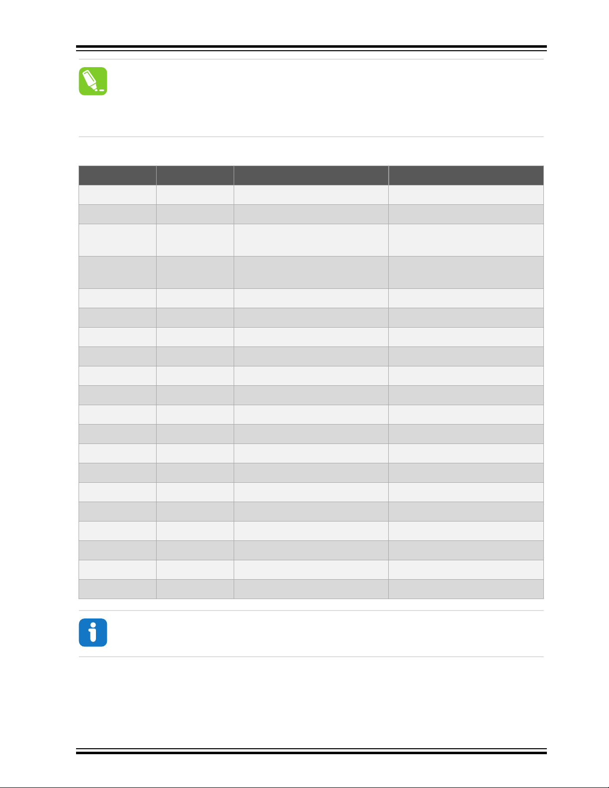
The EDBG controls two LEDs on the SAM E54 Xplained Pro: a power LED and a status LED. The table
below shows how the LEDs are controlled in different operation modes.
© 2017 Microchip Technology Inc.
DS70005321A-page 9
Page 10

SAM E54 Xplained Pro
Table 4-1. EDBG LED Control
Mode Power LED Status LED
Normal mode The power LED is on when
power is applied to the board.
Bootloader mode (idle) The power LED and the status LED blink simultaneously.
Bootloader mode (firmware
The power LED and the status LED blink in an alternating pattern.
upgrade)
For additional information on the EDBG, see the EDBG User Guide.
4.2 Xplained Pro Analog Module (XAM)
4.2.1 Overview
The Xplained Pro Analog Module (XAM) extends the embedded debugger with high dynamic range
current measurement. This enables power profiling of the target system.
Figure 4-1. XAM Block Diagram
Current output
Calibration ON/OFF
Calibration
circuitry
reference
GPIO(s)
GPIO
voltage
2.7V
AREF
Control MCU
Activity indicator, the LED flashes
when any communication
happens to the EDBG.
Sync GPIO
I2C
SPI
Clock sync
SWD
EDBG
Pre-amplifier
Range selection
100 mOhm
Current input
20x
20x
100 Ohm
Xplained Pro Analog Module (XAM)
The XAM consists of:
• Calibration circuitry
• Voltage reference circuitry
• Analog front-end:
– Shunt resistors with a range selection switch
– Pre-amplifier
– Two active filters with gain
• Control MCU
2x
16x
Active filter with
gain
ADC0
ADC1
GND
GPIO
S&H
ADC
© 2017 Microchip Technology Inc.
DS70005321A-page 10
Page 11

– Analog-to-Digital Converter
– Signal processing
– Control/communication interface to the EDBG
The current measurement front-end is a high side shunt measurement with a pre-amplifier and a second
active filter stage with gain as shown in Figure 4-1. The wide dynamic range is achieved by four
measurement ranges, which are defined by two shunt resistors and the two parallel second stage active
filters with gain.
4.2.2 EDBG Interface
The XAM is connected to the EDBG with the following interfaces:
• I2C: This is used to control and configure the XAM.
• SPI: Current measurement data is streamed to the EDBG via this interface. This is a unidirectional
channel from the XAM to the EDBG.
• SWD: The MCU in the XAM is programmed via SWD from the EDBG.
• Clock sync: Signal used to synchronize ADC measurements with the EDBG.
• Reference clock: Reference clock for the XAM.
4.2.3 Sample Rate
The raw sampling rate of the XAM is up to 250 kHz and with the default averaging configuration (average
of 16 samples), the actual output of the XAM is 16.67 ksps.
SAM E54 Xplained Pro
Info: The XAM output sample rate is not an integer fraction of the raw sampling.
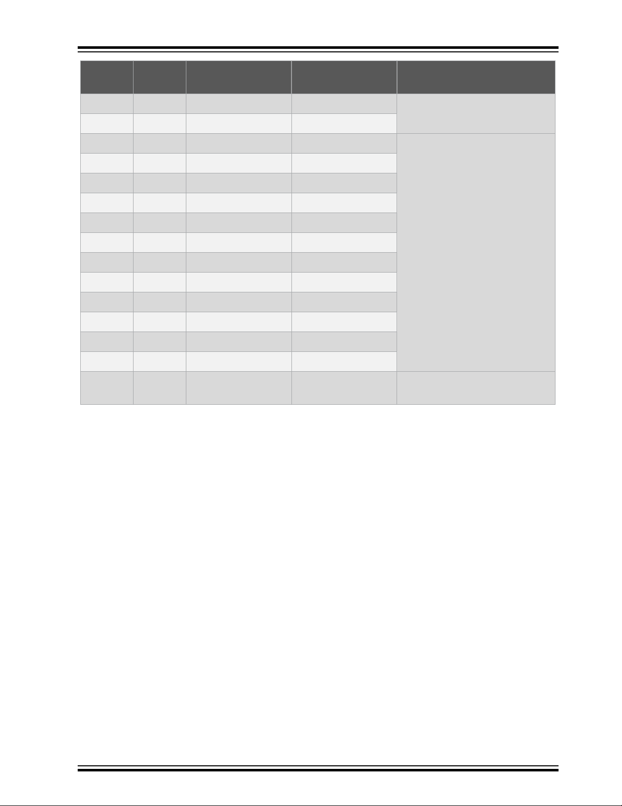
4.2.4 Measurement Ranges and Accuracy
The XAM has four measurement ranges. These are defined by two shunt resistors and two gain stages.
Table 4-2. XAM Measurement Ranges and Accuracy
Measurement
Range
Range 1 Low current shunt and
Range 2 Low current shunt and
Range 3 High current shunt and
Range 4 High current shunt and
Hardware Resolution Accuracy Comments
high gain stage
low gain stage
high gain stage
low gain stage
20 nA 1 LSB ±1% Accuracy will decrease below
1μA. Typical accuracy for
300nA is 1 LSB ± 10%.
150 nA 1 LSB ±1%
10 μA 1 LSB ±1%
100 μA 1 LSB ±1% Accuracy will decrease
above 100 mA. Typical
accuracy is 1 LSB ±5% at
400 mA. Maximum current is
400 mA.
© 2017 Microchip Technology Inc.
DS70005321A-page 11
Page 12

The ranges are automatically switched by the XAM to achieve the best measurement results and the
currently active range is visualized in the Data Visualizer front-end tool. The maximum voltage drop over
the shunt resistor is 100 mV, and the XAM switches the range automatically before reaching this limit.
4.3 Hardware Identification System
All Xplained Pro extension boards come with an identification chip (ATSHA204A CryptoAuthentication
chip) to uniquely identify the boards that are connected to the Xplained Pro evaluation kit. This chip
contains information that identifies the extension with its name and some extra data. When an Xplained
Pro extension is connected to an Xplained Pro evaluation kit, the information is read and sent to Atmel
Studio. The following table shows the data fields stored in the ID chip with example content.
Table 4-3. Xplained Pro ID Chip Content
Data Field Data Type Example Content
Manufacturer ASCII string Atmel'\0'
Product Name ASCII string Segment LCD1 Xplained Pro'\0'
Product Revision ASCII string 02'\0'
Product Serial Number ASCII string 1774020200000010’\0’
SAM E54 Xplained Pro
™
Minimum Voltage [mV] uint16_t 3000
Maximum Voltage [mV] uint16_t 3600
Maximum Current [mA] uint16_t 30
4.4 Power Sources
The SAM E54 Xplained Pro kit can be powered by several power sources, as listed in the table below.
Table 4-4. Power Sources for SAM E54 Xplained Pro
Power Source Voltage Requirements Current Requirements Connector Marking
External Power 5V ±2% (±100mV) for
Embedded debugger
USB
USB host operation.
4.3V to 5.5V if a USB
host operation is not
required.
4.4V to 5.25V (according
to USB spec.)
In USB host applications
a minimum of 1A is
recommended to supply
the kit and the USB
device.
Maximum recommended
current is 2A.
500 mA (according to
USB spec.)
PWR
DEBUG USB
Target USB 4.4V to 5.25V (according
to USB spec.)
The kit automatically detects which power sources are available and chooses which one to use according
to the following priority:
1. External power.
© 2017 Microchip Technology Inc.
500 mA (according to
USB spec.)
TARGET USB
DS70005321A-page 12
Page 13

2. Embedded Debugger USB.
3. Target USB.
Info: External power is required when 500mA from a USB connector is not enough to power
the board with possible extension boards. A connected USB device in a USB host application
might easily exceed this limit.
4.5 Xplained Pro Headers and Connectors
4.5.1 Xplained Pro Standard Extension Header
All Xplained Pro kits have one or more dual row, 20-pin, 100-mil extension header. The Xplained Pro
MCU boards have male headers, while the Xplained Pro extensions have their female counterparts. All
connected pins follow the defined pin description in the table.
Info: All pins are not always connected on all extension headers.
SAM E54 Xplained Pro
The extension headers can be used to connect a variety of Xplained Pro extensions to Xplained Pro MCU
boards or to access the pins of the target microcontroller on Xplained Pro MCU boards directly.
Table 4-5. Xplained Pro Standard Extension Header
Pin Number Pin Name Description
1 ID Pin to communicate with the ID chip on an extension board
2 GND Ground
3 ADC(+) Analog-to-Digital Converter; alternatively, a pin for the positive
terminal of a differential ADC
4 ADC(-) Analog-to-Digital Converter; alternatively, a pin for the negative
terminal of a differential ADC
5 GPIO1 General purpose I/O pin
6 GPIO2 General purpose I/O pin
7 PWM(+) Pulse width modulation; alternatively, a pin for the positive part of a
differential PWM
8 PWM(-) Pulse width modulation; alternatively, a pin for the negative part of a
differential PWM
9 IRQ/GPIO Interrupt request pin and/or general purpose I/O pin
10 SPI_SS_B/
GPIO
11 I2C_SDA Data pin for I2C interface. Always connected, bus type
12 I2C_SCL Clock pin for I2C interface. Always connected, bus type
© 2017 Microchip Technology Inc.
Slave select pin for Serial Peripheral Interface (SPI) and/or general
purpose I/O pin
DS70005321A-page 13
Page 14

Pin Number Pin Name Description
13 UART_RX Receiver pin of target device UART
14 UART_TX Transmitter pin of target device UART
15 SPI_SS_A Slave select for SPI. This pin should preferably not be connected to
16 SPI_MOSI SPI master out slave in pin. Always connected, bus type
17 SPI_MISO SPI master in slave out pin. Always connected, bus type
18 SPI_SCK SPI clock pin. Always connected, bus type
19 GND Ground pin for extension boards
20 VCC Power pin for extension boards
4.5.2 Xplained Pro Power Header
The power header can be used to connect external power to the SAM E54 Xplained Pro kit. The kit
automatically detects and switches to any external power if supplied. The power header can also be used
to supply power to external peripherals or extension boards. Ensure that the total current does not
exceed the recommended current limit of the on-board regulator when using the 3.3V pin.
SAM E54 Xplained Pro
anything else.
Table 4-6. Xplained Pro Power Header
Pin Number Pin Name Description
1 VEXT_P5V0 External 5V input pin
2 GND Ground pin
3 VCC_P5V0
4 VCC_P3V3
Unregulated 5V pin (an output, derived from one of the input
sources)
Regulated 3.3V pin (an output, used as main power supply
for the kit)
© 2017 Microchip Technology Inc.
DS70005321A-page 14
Page 15

5. Hardware User Guide
VCC_P5V0
EDBG & XAM
SAME54P20
Regulator 3.3V
Power source
Power switch
Power converter
Power consumer
VCC_P3V3
Peripherals
Power
Measurement
Select
Auto mux disable
External 5V
input
EDBG USB
Target USB
Auto mux with
current limit
Regulator 3.3V
Jumper
VCC_MCU
VCC_TARGET
Supercap
Select
VBAT
5.1 Power Distribution
SAM E54 Xplained Pro has three power sources: EDBG USB, Target USB, and/or external 5.0V. The kit
will automatically select a source to draw power from. The kit has two on-board 3.3V voltage regulators,
one for the EDBG and XAM, and one for the ATSAME54P20A and other peripherals.
An onboard super capacitor (47 mF) is charged to 3.3V from the target 3.3V net. The super capacitor is
connected to PB03 (VBAT) through a selection header and is intended for backup use in sleep modes.
Figure 5-1. Power Supply Block Diagram
SAM E54 Xplained Pro
5.2 Connectors
The following sections describes the implementation of the relevant connectors and headers on SAM E54
Xplained Pro and their connection to the ATSAME54P20A. The tables of connections in the sections also
describes which signals are shared between the headers and on-board functionality. The figure below
shows all available connectors and jumpers on SAM E54 Xplained Pro.
© 2017 Microchip Technology Inc.
DS70005321A-page 15
Page 16

Figure 5-2. SAM E54 Xplained Pro Connector Overview
SAM E54 Xplained Pro
5.2.1 Xplained Pro Standard Extension Headers
The Xplained Pro extension headers EXT1, EXT2, and EXT3 offer access to the I/O of the microcontroller
to expand the board, for example, by connecting extensions to the board. These headers are based on
the standard Xplained Pro extension header specification and the connections are shown in the table
below. The headers have a pitch of 2.54 mm.
© 2017 Microchip Technology Inc.
DS70005321A-page 16
Page 17

Table 5-1. Extension Header EXT1
SAM E54 Xplained Pro
EXT1 pin SAM E54
pin
1 [ID] - - Communication line to the ID
2 [GND] - - Ground
3 [ADC(+)] PB04 ADC1/AIN[6] -
4 [ADC(-)] PB05 ADC1/AIN[7] -
5 [GPIO1] PA06 GPIO (RTS) -
6 [GPIO2] PA07 GPIO (CTS) -
7 [PWM(+)] PB08 TC4/WO[0] -
8 [PWM(-)] PB09 TC4/WO[1] -
9 [IRQ/GPIO] PB07 IRQ7/GPIO -
10 [SPI_SS_B/GPIO] PA27 GPIO -
11 [TWI_SDA] PA22 SERCOM3 PAD[0] I²C SDA PCC
12 [TWI_SCL] PA23 SERCOM3 PAD[1] I²C SCL PCC
13 [USART_RX] PA05 SERCOM0 PAD[1] UART RX -
Function Shared functionality
chip on an extension board
14 [USART_TX] PA04 SERCOM0 PAD[0] UART TX -
15 [SPI_SS_A] PB28 SERCOM4 PAD[2] SPI SS -
16 [SPI_MOSI] PB27 SERCOM4 PAD[0] SPI MOSI -
17 [SPI_MISO] PB29 SERCOM4 PAD[3] SPI MISO -
18 [SPI_SCK] PB26 SERCOM4 PAD[1] SPI SCK -
19 [GND] - - Ground
20 [VCC] - - Power for extension board
Table 5-2. Extension Header EXT2
EXT2 pin SAM E54
pin
1 [ID] - - Communication line to the ID
2 [GND] - - Ground
3 [ADC(+)] PB00 ADC0/AIN[12] -
4 [ADC(-)] PA03 ADC0/AIN[1] -
5 [GPIO1] PB01 GPIO -
Function Shared functionality
chip on an extension board
6 [GPIO2] PB06 GPIO -
7 [PWM(+)] PB14 TCC4/WO[4] PCC
© 2017 Microchip Technology Inc.
DS70005321A-page 17
Page 18

SAM E54 Xplained Pro
EXT2 pin SAM E54
pin
8 [PWM(-)] PB15 TCC4/WO[5] PCC
9 [IRQ/GPIO] PD00 IRQ0/GPIO -
10 [SPI_SS_B/GPIO] PB02 GPIO -
11 [TWI_SDA] PD08 SERCOM7 PAD[0] I²C SDA AT24MAC402, ATECC508, PCC,
12 [TWI_SCL] PD09 SERCOM7 PAD[1] I²C SCL AT24MAC402, ATECC508, PCC,
13 [USART_RX] PB17 SERCOM5 PAD[1] UART RX -
14 [USART_TX] PB16 SERCOM5 PAD[0] UART TX -
15 [SPI_SS_A] PC06 SERCOM6 PAD[2] SPI SS -
16 [SPI_MOSI] PC04 SERCOM6 PAD[0] SPI MOSI EXT3 and EDBG DGI
17 [SPI_MISO] PC07 SERCOM6 PAD[3] SPI MISO EXT3 and EDBG DGI
18 [SPI_SCK] PC05 SERCOM6 PAD[1] SPI SCK EXT3 and EDBG DGI
19 [GND] - - Ground
Function Shared functionality
EXT3, and EDBG DGI
EXT3, and EDBG DGI
20 [VCC] - - Power for extension board
Table 5-3. Extension Header EXT3
EXT3 pin SAM E54
pin
1 [ID] - - Communication line to the ID
2 [GND] - - Ground
3 [ADC(+)] PC02 ADC1/AIN[4]
4 [ADC(-)] PC03 ADC1/AIN[5]
5 [GPIO1] PC01 GPIO
6 [GPIO2] PC10 GPIO -
7 [PWM(+)] PD10 TCC0/WO[3] -
8 [PWM(-)] PD11 TCC0/WO[4] -
9 [IRQ/GPIO] PC30 IRQ14/GPIO -
10 [SPI_SS_B/GPIO] PC31 GPIO -
11 [TWI_SDA] PD08 SERCOM7 PAD[0] I²C SDA AT24MAC402, ATECC508, PCC,
Function Shared functionality
chip on an extension board
EXT2, and EDBG DGI
12 [TWI_SCL] PD09 SERCOM7 PAD[1] I²C SCL AT24MAC402, ATECC508, PCC,
EXT2, and EDBG DGI
© 2017 Microchip Technology Inc.
DS70005321A-page 18
Page 19

SAM E54 Xplained Pro
EXT3 pin SAM E54
13 [USART_RX] PC23 SERCOM1 PAD[1] UART RX -
14 [USART_TX] PC22 SERCOM1 PAD[0] UART TX -
15 [SPI_SS_A] PC14 GPIO -
16 [SPI_MOSI] PC04 SERCOM6 PAD[0] SPI MOSI EXT2 and EDBG DGI
17 [SPI_MISO] PC07 SERCOM6 PAD[3] SPI MISO EXT2 and EDBG DGI
18 [SPI_SCK] PC05 SERCOM6 PAD[1] SPI SCK EXT2 and EDBG DGI
19 [GND] - - Ground
20 [VCC] - - Power for extension board
5.2.2 SD/SDIO Card
SAM E54 Xplained Pro has one standard SD card connector which is connected to the SD/MMC Host
Controller (SDHC) of the SAM E54. The table below lists all I/O-lines connected to the SD card
connector.
Table 5-4. SD/SDIO Card Connection
SAM E54 pin Function Shared functionality
Function Shared functionality
pin
PB18 MCDA0 (DAT0)
PB19 MCDA1 (DAT1)
PB20 MCDA2 (DAT2)
PB21 MCDA3 (DAT3)
PA21 MCCK (CLK) PCC
PA20 MCCDA (CMD) PCC
PD20 Card Detect (C/D) -
PD21 Write Protect (WP) -
5.2.3 PCC Camera Connector
A 2x10, 100-mil pin-header footprint for camera connector is implemented to give access to the SAM
E54's Parallel Capture Controller (PCC). The footprint is compatible with common ArduCAM modules.
Info: The PCC connector is not functional by default due to shared functionality with Ethernet,
QTouch, SD Card, EXT1, and EXT2. If using the PCC, you will partially or fully loose the ability
to use these other functions.
Info: Soldering is required to get the PCC functional. Refer to Kit Modifications for details on
modifications needed.
© 2017 Microchip Technology Inc.
DS70005321A-page 19
Page 20
SAM E54 Xplained Pro
Tip: The DEN1 and DEN2 signals connected to VSYNC and HYSNC on the PCC camera
connector are used to tell the PCC module when there is valid data to sample on the data pins.
If interrupts are required when the DEN1 and DEN2 signals changes, the I/O pins (PA12 and
PA13) has to be multiplexed to the EIC function in the GPIO module. The PCC module will still
sample the DEN pins when they are multiplexed to the EIC function.
Table 5-5. PCC Camera Connector
Pin number SAM E54 pin Function Shared functionality
1 [VCC] - VCC_TARGET_P3V3
2 [GND] - GND
3 [SCL] PD09 SERCOM7 PAD[1] I²C SCL AT24MAC402, ATECC508,
EXT2, EXT3, and EDBG DGI
4 [SDA] PD08 SERCOM7 PAD[0] I²C SDA AT24MAC402, ATECC508,
EXT2, EXT3, and EDBG DGI
5 [VSYNC] PA12 PCC_DEN1 Ethernet
6 [HSYNC] PA13 PCC_DEN2 Ethernet
7 [PCLK] PA14 PCC_CLK Ethernet
8 [XCLK] PA15 GCLK_IO1 Ethernet
9 [DOUT07] PA23
10 [DOUT06] PA22
11 [DOUT05] PA21
12 [DOUT04] PA20
1)
1)
1)
1)
PCC_DATA7 EXT1
PCC_DATA6 EXT1
PCC_DATA5 SD Card
PCC_DATA4 SD Card
13 [DOUT03] PA19 PCC_DATA3 Ethernet
14 [DOUT02] PA18 PCC_DATA2 Ethernet
15 [DOUT01] PA17 PCC_DATA1 Ethernet
16 [DOUT00] PA16 PCC_DATA0 QTouch
17 [DOUT09] PB15 PCC_DATA9 EXT2
18 [DOUT08] PB14 PCC_DATA8 EXT2
19 [RESET] PC12 GPIO Ethernet
20 [PWDN] PC11 GPIO Ethernet
Info:
1) Connected through a 0Ω resistor. Not connected by default.
© 2017 Microchip Technology Inc.
DS70005321A-page 20
Page 21

5.2.4 Position Decoder
SAM E54 Xplained Pro has a header footprint for the position decoder module. The PDEC can be used
for quadrature, hall, and counter decoding.
Info: External pull-ups are mounted on the three signal lines for use with passive quadrature
encoders.
Table 5-6. PDEC Header
J407 pin SAM E54 pin Function Shared functionality
1 [PHASE A] PC16 PDEC QDI[0] EDBG GPIO0
2 [PHASE B] PC17 PDEC QDI[1] EDBG GPIO1
3 [INDEX] PC18 PDEC QDI[2] EDBG GPIO2 and User LED
4 - GND -
5.2.5 VBAT Backup Select
There is a 1x3, 100mil pin-header on the kit that can be used to select a power source for the VBAT pin
(PB03) marked "VBAT Select". The power source can either be the onboard 3.3V that supplies the other
peripherals on the board, or the onboard super capacitor. To select the source for the VBAT pin, move the
jumper to the desired voltage by placing the jumper between pin 1-2 for the super capacitor, or between
pin 2-3 for the targets MCU voltage. If power to the VBAT pin is not needed, the jumper can be removed
and PB03 at the center pin can be used as a GPIO.
SAM E54 Xplained Pro
Table 5-7. VBAT Select Header
Pin Function Description
1 VCC_SUPERCAP Power from super capacitor
2 PB03 VBAT input pin on SAM E54
3 VCC_MCU_P3V3 Power from the target MCU supply
5.2.6 ADC/DAC Header
There is a 1x2, 100mil pin-header on the kit that can be used for connecting analog peripherals for use
with the built in ADC or DAC.
Table 5-8. ADC/DAC Header
Pin number Pin/Net Function Shared functionality
1 PA02 ADC0/AIN0 or DAC/
2 GND Ground -
5.2.7 USB
SAM E54 Xplained Pro has a USB Micro-AB connector for use with the SAM E54 USB module labeled
TARGET USB on the kit. To be able to detect when a target USB cable is connected in self-powered
mode, a GPIO is used to detect the VBUS voltage on the connector. The USB ID is connected to a power
switch, which will automatically enable power to the USB port if a device cable is detected. The USB ID
-
VOUT0
© 2017 Microchip Technology Inc.
DS70005321A-page 21
Page 22

signal is connected to PC19, which can force power from the kit to the USB connector by driving PC19
low. It is not possible to override and disable the power if a device is connected as the device cable will
short the USB ID to ground.
Table 5-9. USB Connections
SAM E54 pin USB function
PC00 VBUS Detection
PC19 USB ID
PA24 USB D-
PA25 USB D+
5.2.8 Cortex Debug Connector
SAM E54 Xplained Pro has a 10-pin 50-mil Cortex Debug Connector with SWD that can be used to
attach external debuggers to the ATSAME54P20A. Microchip debugging tools like the Atmel-ICE and
Power Debugger can connect directly to this connector.
Table 5-10. Cortex Debug Connector
SAM E54 Xplained Pro
Cortex Debug
Connector pin
1 [VCC] VCC_TARGET_P3V3 ATSAME54P20A
2 [SWDIO/TMS] PA31 SW bidirectional data TRACE and EDBG
3 [GND] GND Ground
4 [SWCLK/TCK] PA30 SW clock signal TRACE and EDBG
5 [GND] GND Ground
6 [SWO/TDO] PB30 SW output TRACE and EDBG
7 [KEY] - -
8 [NC/TDI] - -
9 [GNDDetect] GND Ground
10 [nRESET] RESETN Target reset signal RST BTN, TRACE, and
Pin/Net Function Shared functionality
voltage
SWD
SWD
SWD
EDBG SWD
5.2.9 Cortex Debug Connector with Trace
ATSAME54P20A supports 4-bit parallel trace. SAM E54 Xplained Pro implements a 20-pin, 50-mil Cortex
Debug + ETM Connector with SWD and 4-bit parallel trace. The connector is keyed (pin 7 is removed).
To use the parallel trace functionality an external debugger with trace support and 20-pin Cortex Debug +
ETM Connector pin-out has to be used. The table below shows the connections on the kit.
© 2017 Microchip Technology Inc.
DS70005321A-page 22
Page 23

SAM E54 Xplained Pro
Table 5-11. Cortex Debug + ETM Connector
Pin number Pin/Net Function Shared functionality
1 [VTREF] VCC_TARGET_P3V3 ATSAME54P20A
voltage
2 [TMS/SWDIO] PA31 SWDIO Cortex DBG and EDBG
SWD
3 [GND] GND Ground
4 [TCK/SWCLK] PA30 SWCLK Cortex DBG and EDBG
SWD
5 [GND] GND Ground
6 [TDO/SWO] PB30 SWO Cortex DBG and EDBG
SWD
7 [KEY] - Not connected, the pin is
removed.
8 [TDI] - -
9 [GND] GND Ground
10 [nSRST] RESET_N Reset RST BTN, Cortex DBG,
11 [NC] - -
12 [RTCK/TRACECLK] PC27 TRACECLK
13 [NC] - -
14 [SWO/D0] PC28 TRACEDATA[0]
15 [GND] GND Ground
16 [ntRST/D1] PC26 TRACEDATA[1]
17 [GND] GND Ground
18 [DBGRQ/D2] PC25 TRACEDATA[2]
19 [GND] GND Ground
20 [DBGACK/D3] PC24 TRACEDATA[3]
5.2.10 Current Measurement Header
An angled 1x2, 100-mil pin header marked with the MCU current measurement is located at the upper
edge of the SAM E54 Xplained Pro. All power to the ATSAME54P20A is exclusively routed through this
header (excluding power to headers and peripherals). To measure the power consumption of the device,
remove the jumper and replace it with an ammeter.
and EDBG SWD
Caution: Removing the jumper from the pin header while the kit is powered may cause the
ATSAME54P20A to be powered through its I/O pins. This may cause permanent damage to the
device.
© 2017 Microchip Technology Inc.
DS70005321A-page 23
Page 24

5.3 Peripherals
5.3.1 Crystals
SAM E54 Xplained Pro has a 32.768 kHz and a 12 MHz crystal that can be used as clock source for the
SAM E54 device. There are cut-straps located close to the crystals that can be used to measure the
oscillator safety factor. This is done by cutting the strap and adding a resistor across the strap. More
information about oscillator allowance and safety factor are available in the AVR4100 application note.
The 32.768 kHz crystal on SAM E54 Xplained Pro is a Kyocera Crystal Device Corporation
ST3215SB32768A0HPWBB 5pF crystal. The crystal has been matched to be driven in high drive mode
by the SAM E54.
The 12 MHz crystal on SAM E54 Xplained Pro is a Kyocera Crystal Device Corporation
CX3225CA12000D0KPSC1. The crystal has been matched to be driven with Automatic Loop Control
enabled in the SAM E54.
Both crystals have been formally tested and matched to the SAM E54 by Kyocera. The test reports are
available in the design documentation distributed with this document for SAM E54 Xplained Pro.
Info: Kyocera Crystal Device Corporation crystals that are matched with specific products can
be found on their web site: http://prdct-search.kyocera.co.jp/crystal-ic/?p=en_search/
SAM E54 Xplained Pro
Table 5-12. External 32.768kHz Crystal
SAM E54 pin Function
PA00 XIN32
PA01 XOUT32
Table 5-13. External 12MHz Crystal
SAM E54 pin Function
PB22 XIN1
PB23 XOUT1
Related Links
Design Documentation and Relevant Links
5.3.2 Mechanical Buttons
SAM E54 Xplained Pro contains two mechanical buttons. One button is the RESET button connected to
the SAM E54 reset line and the other is a generic user configurable button. When a button is pressed it
will drive the I/O line to GND.
Info: There is no pull-up resistor connected to the generic user button. Remember to enable
the internal pull-up in the SAM E54 to use the button.
© 2017 Microchip Technology Inc.
DS70005321A-page 24
Page 25

Table 5-14. Mechanical Buttons
SAM E54 pin Silkscreen text Shared functionality
RESET RESET Cortex DBG , TRACE, and EDBG SWD
PB31 SW0 EDBG GPIO3
5.3.3 LED
There is one yellow LED available on the SAM E54 Xplained Pro board that can be turned ON and OFF.
The LED can be activated by driving the connected I/O line to GND.
Table 5-15. LED Connection
SAM E54 pin Function Shared functionality
PC18 Yellow LED0 PDEC and EDBG GPIO2
5.3.4 QTouch Button
There is one self capacitance button available on the SAM E54 Xplained Pro board that can be used as
user button. This QTouch button is intended to be driven by the built-in Peripheral Touch Controller (PTC)
of the device.
SAM E54 Xplained Pro
Info: To get started with QTouch, refer to QTouch® Library, or find examples in Atmel START.
Table 5-16. QTouch Connection
SAM E54 pin Silkscreen text Shared functionality
PA16 QT BUTTON PCC
5.3.5 Backup Super Capacitor
SAM E54 Xplained Pro has a 47 mF backup super capacitor for use with the SAM E54 backup system.
The super capacitor can be connected to the device as described in VBAT Backup Select.
Due to the high capacitive load represented by the super capacitor, a 220Ω limiting resistor is added to
reduce inrush current. The source for charging is the targets main supply and a low-power opamp is used
for disconnecting the charger input when removing power. This is added to avoid a current leak back to
the main supply from the super capacitor when power is removed.
A full charge of the super capacitor from an empty state will take approximately 45 seconds and can
supply the target device in backup mode with ULP running for up to ~20 hours. Other modes are not
characterized, but will reduce the available time in backup mode respectively. For more information about
the current consumption in other modes, refer to the electrical characteristics chapter in the SAM E54
datasheet.
Caution: Due to an issue with the VBAT pin in the A0 revision of ATSAME54P20A there is an
over-consumption of current in the VBAT pin when VBAT > VDDIO. This issue renders the onboard super capacitor backup solution not usable.
Related Links
© 2017 Microchip Technology Inc.
DS70005321A-page 25
Page 26

VBAT Pin
5.3.6 CAN
SAM E54 Xplained Pro has two CAN modules that performs communication according to ISO11898-1
(Bosch CAN specification 2.0 part A,B) and Bosch CAN FD specification V1.0.
CAN1 is connected to an on-board ATA6561 CAN physical-layer transceiver, the table below shows
connections between the ATSAME54P20A and the ATA6561.
Table 5-17. ATA6561 Connections
SAM E54 pin Function ATA6561 function Shared functionality
PB12 CAN1/TX TXD -
PB13 CAN1/RX RXD -
PC13 GPIO Standby -
5.3.7 Ethernet
ATSAME54P20A has a built-in 10/100Mbps Ethernet IEEE® 802.3 compatible MAC with RMII interface.
The MAC also supports energy efficient Ethernet (IEEE 802.3az). SAM E54 Xplained Pro connects the
MAC to a Micrel KSZ8091RNACA RMII physical-layer transceiver (PHY), with IEEE 802.3az support,
which is connected to one RJ45 Ethernet connector.
SAM E54 Xplained Pro
A unique EUI-48 address is available on every SAM E54 Xplained Pro through the onboard
AT24MAC402, the EUI-48 address can be used as a MAC address for the KSZ8091RNACA. The
address is also programmed into the onboard EDBG. For more information, see Kit Specific Data.
The table below lists all pins connected from the ATSAME54P20A to the Ethernet PHY.
Info: Several of the Ethernet signals are shared with the PCC connector. This means that
there is no Ethernet support if PCC is used in an application.
Table 5-18. KSZ8061RNBW Connections
SAM E54 pin Function Ethernet function Shared functionality
PA14 GTXCK REF_CLK PCC
PA17 GTXEN TXEN PCC
PA18 GTX0 TXD0 PCC
PA19 GTX1 TXD1 PCC
PC20 GRXDV CRS_DV
PA13 GRX0 RXD0 PCC
PA12 GRX1 RXD1 PCC
PA15 GRXER RXER PCC
PC11 GMDC MDC PCC
PC12 GMDIO MDIO PCC
© 2017 Microchip Technology Inc.
DS70005321A-page 26
Page 27

SAM E54 pin Function Ethernet function Shared functionality
PD12 GPIO INTERRUPT
PC21 GPIO RESET
The KSZ8091RNACA also has a set of parameters that are latched in during reset based on I/O pin
levels. These configuration options have a default mode on the kit done by external pull-up and pull-down
resistors. For detailed information about the configuration, see the KSZ8091RNACA datasheet.
Table 5-19. KSZ8091RNACA Kit Configuration
Configuration name Default value on kit Default configuration
PHYAD 00 The PHYs address is 00000
PME_EN 0 Disable PME Enable output for
ANEN_SPEED 1 Auto negotiation enabled and
5.3.8 AT24MAC402
SAM E54 Xplained Pro features one external AT24MAC402 serial EEPROM with a EIA-48 MAC address
connected to the SAM E54 through I2C. This device contain a MAC address for use with the Ethernet
interface. The table below lists all I/O-lines connected to the ATMAC402 device.
SAM E54 Xplained Pro
Wake-On-LAN
100Mbps link speed enabled
Info: The I2C EEPROM address is 0x56 and extended address is 0x5E (7-bit, right adjusted
without R/W bit).
Table 5-20. AT24MAC402 Connections
AT24MAC402
pin
1 [A0] - Address bit 0 config (Pulled to
2 [A1] - Address bit 1 config (Pulled to
3 [A2] - Address bit 2 config (Pulled to
4 [GND] - GND -
5 [SDA] PD08 SERCOM7 PAD[0] I2C SDA ATECC508, PCC, EXT2, EXT3,
6 [SCL] PD09 SERCOM7 PAD[1] I2C SCL ATECC508, PCC, EXT2, EXT3,
SAM E54 pin Function Shared functionality
-
GND)
-
VCC)
-
VCC)
and EDBG DGI
and EDBG DGI
7 [WP] - Write Protect (Pulled to GND) -
© 2017 Microchip Technology Inc.
DS70005321A-page 27
Page 28

SAM E54 Xplained Pro
AT24MAC402
pin
8 [VCC] - VCC_TARGET_P3V3 -
9 [PAD] - - -
5.3.9 ATECC508A
SAM E54 Xplained Pro implements a ATECC508A Crypto Authentication device. The table below shows
all the connections between the ATECC508A and the ATSAME54P20A.
Info: The I2C address is 0x60 (7-bit, right adjusted without R/W bit).
Table 5-21. ATECC508A Connections
ATECC508A
pin
1 [NC] - - -
2 [NC] - - -
SAM E54 pin Function Shared functionality
SAM E54 pin Function Shared functionality
3 [NC] - - -
4 [GND] - GND -
5 [SDA] PD08 SERCOM7 PAD[0] I2C SDA AT24MAC402, PCC, EXT2,
6 [SCL] PD09 SERCOM7 PAD[1] I2C SCL AT24MAC402, PCC, EXT2,
7 [NC] - -
8 [VCC] - VCC_TARGET_P3V3 -
9 [PAD] - GND -
5.3.10 QSPI Flash
The SAM E54 Xplained Pro features one external MICRON, N25Q256A, 256Mbit QSPI NOR Flash
Memory. QSPI Flash access can be configured in the QSPI module in the SAM E54, with support for XIP
to run firmware directly from external flash. The table below lists all I/O-lines connected to the QSPI
Flash.
Info: The PCB tracks between the QSPI flash and the ATSAME54P20A are routed with 60Ω
impedance. The I/O drivers in the ATSAME54P20A should be set in high drive mode. The QSPI
flash I/O drive level can be configured to match 60Ω tracks in configuration registers in the QSPI
flash, refer to the QSPI datasheet for more information.
EXT3, and EDBG DGI
EXT3, and EDBG DGI
© 2017 Microchip Technology Inc.
DS70005321A-page 28
Page 29

Table 5-22. QSPI Flash Connections
SAM E54 Xplained Pro
SAM E54
pin
PA08 QIO0 Slave In/IO0 -
PA09 QIO1 Slave Out/IO1 -
PA10 QIO2 Write Protect/IO2 -
PA11 QIO3 Hold/IO3 -
PB10 QSCK Clock -
PB11 QCS Chip Select -
5.3.11 I2S Signals
The ATSAME54P20A has a built in two channel Inter-IC Sound Controller (I2S).
There is no on-board IC connected to this module, but the signals are available on the different pinheaders on the kit as shown in the table below.
Table 5-23. I2S Signals on SAM E54 Xplained Pro
Microcontroller Pin I2S Signal Pin-Header Location On-board Shared
PB16 SCK0 EXT2 pin 14
PB17 MCK0 EXT2 pin 13
PA20 FS0 Camera pin 12
PA21 SDO Camera pin 11
Function QSPI Flash function Shared functionality
1)
1)
SDCARD MCCDA
SDCARD MCCK
PA22 SDI EXT1 pin 11 / Camera
1)
pin 10
PA23 FS1 EXT1 pin 12 / Camera
1)
pin 9
PB28 SCK1 EXT1 pin 15
PB29 MCK1 EXT1 pin 17
Info:
1) Soldering is required to connect these pins to the camera connector. The resistor footprint
R205, R206, R207, and R208 have to be populated by 0-ohm resistors. The location of the
footprints can be found in the Kit Modifications chapter.
Info: The I2S module can use more pins than listed in the table above. These signals are not
listed in the table as they are shared with the on-board QSPI Flash and CAN transceiver.
Related Links
Kit Modifications
© 2017 Microchip Technology Inc.
DS70005321A-page 29
Page 30

5.4 Embedded Debugger Implementation
SAM E54 Xplained Pro contain an Embedded Debugger (EDBG) that can be used to program and debug
the ATSAME54P20A using Serial Wire Debug (SWD). The Embedded Debugger also includes a Virtual
Com port interface over UART, a Data Gateway Interface over SPI, and I2C, and it includes four of the
SAM E54 GPIOs. The kit also includes an XAM extension processor to the Embedded Debugger for onboard current measurement. Atmel Studio can be used as a front end for the Embedded Debugger.
5.4.1 Serial Wire Debug
The Serial Wire Debug (SWD) uses two pins to communicate with the target. For further information on
how to use the programming and debugging capabilities of the EDBG, see Embedded Debugger.
Table 5-24. SWD Connections
SAM E54 pin Function Shared functionality
PA30 SWCLK clock Cortex DBG and TRACE
PA31 SWDIO data Cortex DBG and TRACE
PB30 SWO output Cortex DBG and TRACE
RESET_N RESET Cortex DBG, TRACE, and RST BTN
SAM E54 Xplained Pro
5.4.2 Virtual COM Port
The Embedded Debugger acts as a Virtual Com Port gateway by using one of the ATSAME54P20A
UARTs. For further information on how to use the Virtual COM port, see Embedded Debugger.
Table 5-25. Virtual COM Port Connections
SAM E54 pin Function Shared functionality
PB24 SERCOM2 PAD[1] UART RXD (SAM E54 RX line) -
PB25 SERCOM2 PAD[0] UART TXD (SAM E54 TX line) -
5.4.3 Data Gateway Interface
The Embedded Debugger features a Data Gateway Interface (DGI) by using either an SPI or I2C. The
DGI can be used to send a variety of data from the ATSAME54P20A to the host PC. For further
information on how to use the DGI interface, see Data Visualizer and the EDBG User Guide.
Table 5-26. DGI Interface Connections when using SPI
SAM E54 pin Function Shared functionality
PD01 GPIO SPI SS (Slave select) (SAM E54
is Master)
PC04 SERCOM6 PAD[0] SPI MOSI (Master
Out, Slave in)
-
EXT2 and EXT3
PC07 SERCOM6 PAD[3] SPI MISO (Master
In, Slave Out)
PC05 SERCOM6 PAD[1] SPI SCK (Clock Out) EXT2 and EXT3
© 2017 Microchip Technology Inc.
EXT2 and EXT3
DS70005321A-page 30
Page 31

SAM E54 Xplained Pro
Table 5-27. DGI Interface Connections when using I2C
SAM E54 pin Function Shared functionality
PD08 SERCOM7 PAD[0] SDA (Data line) AT24MAC402, ATECC508, PCC, EXT2,
and EXT3
PD09 SERCOM7 PAD[1] SCL (Clock line) AT24MAC402, ATECC508, PCC, EXT2,
and EXT3
Four GPIO lines are connected to the Embedded Debugger. The EDBG can monitor these lines and time
stamp pin value changes. This makes it possible to accurately time stamp events in the SAM E54
application code. For further information on how to configure and use the GPIO monitoring features, see
Data Visualizer and the EDBG User Guide.
Table 5-28. GPIO Lines Connected to the EDBG
SAM E54 pin Function Shared functionality
PC16 GPIO0 PDEC
PC17 GPIO1 PDEC
PC18 GPIO2 PDEC and User LED
PB31 GPIO3 User SW0
5.4.4 XAM Configuration
On the SAM E54 Xplained Pro the MCU and the MCU peripherals (e.g. extensions) are powered by its
own regulator as shown in the figure below. All other parts of the board, mainly embedded debugger and
accompanying Xplained Pro Analog Module (XAM), are powered from a separate regulator. The current
to the MCU and peripherals can be measured by connecting them to the XAM output through jumper
settings.
© 2017 Microchip Technology Inc.
DS70005321A-page 31
Page 32

SAM E54 Xplained Pro
Figure 5-3. SAM E54 Xplained Pro XAM Implementation Block Diagram
Xplained Pro MCU power
measurement jumper
Target
Peripherals
Current measurement
bypass jumper selection
Xplained Pro Analog
Module (XAM)
Target MCU
On the SAM E54 Xplained Pro the XAM can be used in four configurations:
1. No current measurement or external MCU current measurement: The XAM is bypassed and
thus the MCU and peripherals are supplied directly by the regulator. Set both jumpers in the
"BYPASS" position. In this configuration it is also possible to connect external measurement tools
on the Xplained Pro MCU power measurement header to measure MCU current directly instead of
using the XAM.
2. MCU current measurement: The XAM measures only the MCU current while the peripherals are
supplied directly by the regulator. For this configuration place the jumper for "I/O" (peripherals) into
the "BYPASS" position and the "MCU" into the "MEASURE" position.
3. Peripherals measurement: The XAM measures only the peripherals current while the MCU is
directly supplied by the regulator. For this configuration place the jumper for "MCU" into the
"BYPASS" position and the "I/O" jumper into the "MEASURE" position.
4. MCU and peripherals measurement: In this configuration both the MCU and peripherals are
measured by the XAM. Place both jumpers on "I/O" and "MCU" headers in the "MEASURE"
position.
5.5 Kit Modifications
SAM E54 Xplained Pro has several resistors that can be used to disconnect I/O pins of the
ATSAME54P20A from connectors and on-board ICs, and to disconnect power signals.
Target
Regulator
© 2017 Microchip Technology Inc.
DS70005321A-page 32
Page 33

SAM E54 Xplained Pro
Info: Note that there are some resistors that aren't mounted by default on the kit listed in the
table below.
Table 5-29. Resistors
DesignatorValue From To Comment
J101 cut-strap VCC_P3V3 VCC_P3V3_CM_IN ATSAME54P20A, peripherals
and connectors power supply
R101 0Ω U100 OUT VCC_CM_P3V3 XAM power supply
R103 0Ω U100 OUT VCC_EDBG_P3V3 EDBG power supply
R205 0Ω [N.M.] J406 PCC DATA04 PA20 SDHC CMD Allows complete or partial
R206 0Ω [N.M.] J406 PCC DATA05 PA21 SHDC CK
R207 0Ω [N.M.] J406 PCC DATA06 PA22 I2C HS SDA
R208 0Ω [N.M.] J406 PCC DATA07 PA23 I2C HS SCL
R308 10kΩ PCC DATA0 QTouch Button
R621 0Ω PA17 ETH GTXEN PHY_TXEN
disconnect of header J406,
Parallel Capture Controller,
header from ATSAME54P20A,
and shared signals. Remove the
mounted resistors and mount the
unmounted resistors if using the
PCC header.
R622 0Ω PA18 ETH GTX0 PHY_TXD0
R623 0Ω PA19 ETH GTX1 PHY_TXD1
R624 0Ω PA13 ETH GRX0 PHY_RXD0
R625 0Ω PA12 ETH GRX1 PHY_RXD1
R626 0Ω PA15 ETH GRXER PHY_RXER
R628 0Ω PC12 ETH GMDIO PHY_MDIO
R629 0Ω PC11 ETH GMDC PHY_MDC
R630 0Ω PA14 ETH GTXCK PHY_REFCLK
R609 4.7kΩ
[N.M.]
R616 1kΩ PHYAD GND
R613 4.7kΩ
[N.M.]
R618 1kΩ
[N.M.]
R605 4.7kΩ ANEN_SPEED VCC_TARGET_P3V3
PHYAD VCC_TARGET_P3V3 Configuration for default start-up
PME_EN VCC_TARGET_P3V3
PME_EN GND
conditions for the Ethernet PHY.
R619 1kΩ ANEN_SPEED GND
R802 39Ω EDBG TARGET
RESET
R803 0Ω EDBG SWCLK PA30 SWCLK
© 2017 Microchip Technology Inc.
TARGET MCU
RESET
Debug interface from the EDBG
to the ATSAME54P20A
DS70005321A-page 33
Page 34
SAM E54 Xplained Pro
DesignatorValue From To Comment
R824 0Ω EDBG SWDIO PA31 SWDIO
R827 0Ω EDBG SWO PB30 SWO
R808 0Ω EDBG CDC RX PB25 UART TX EDBG CDC and DGI interfaces
R809 330Ω EDBG CDC TX PB24 UART RX
R810 330Ω EDBG DGI_GPIO0 PC16 GPIO
R811 330Ω EDBG DGI_GPIO1 PC17 GPIO
R813 0Ω EDBG I2C SDA PD08 I2C SDA
R814 0Ω EDBG I2C SCL PD09 I2C SCL
R815 330Ω EDBG SPI MISO PC07 SPI MISO
R816 0Ω EDBG SPI MOSI PC04 SPI MOSI
R817 0Ω EDBG SPI SCK PC05 SPI SCK
R818 0Ω EDBG SS PD01 SPI SS
to the ATSAME54P20A
R825 330Ω EDBG DGI_GPIO2 PC18 GPIO
R826 330Ω EDBG DGI_GPIO3 PB31 GPIO
R812 0Ω TARGET RESET
SENSE
TARGET_MCU_RESETReset sense signal to EDBG,
used to detect external resets
© 2017 Microchip Technology Inc.
DS70005321A-page 34
Page 35

Figure 5-4. Assembly Drawing Top
SAM E54 Xplained Pro
© 2017 Microchip Technology Inc.
DS70005321A-page 35
Page 36
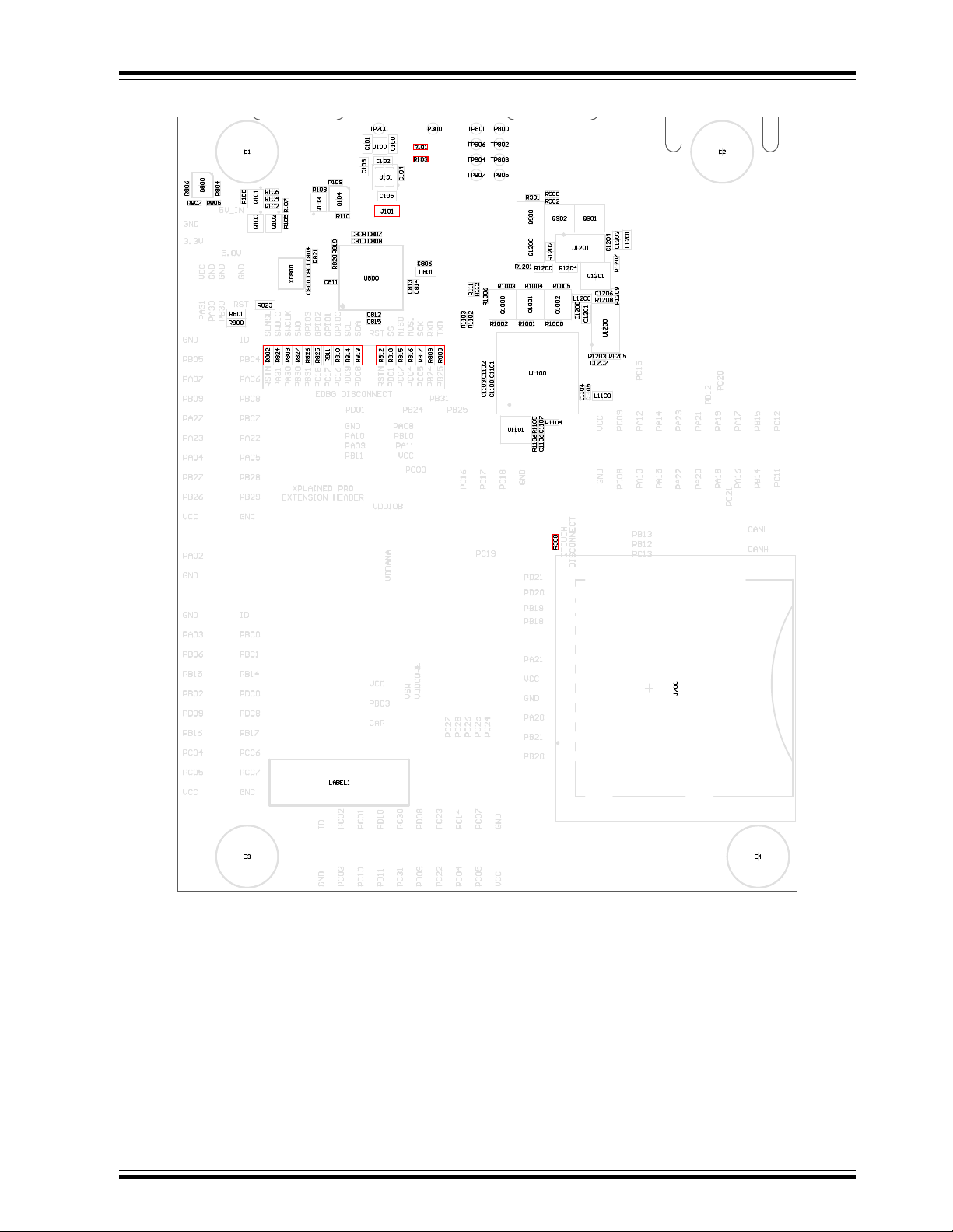
Figure 5-5. Assembly Drawing Bottom
SAM E54 Xplained Pro
5.5.1 Enable PCC Header
The PCC header on the SAM E54 Xplained Pro board is by default not functional due to shared
connections with Ethernet, QTouch, SD Card, EXT1, and EXT2.
To modify the kit to fully enable the PCC header, do the following:
• Remove the resistors: R621, R622, R623, R624, R625, R626, R628, R629, R630 to separate the
Ethernet PHY from the lines
• Mount 0Ω resistors: R205, R206, R207, R208
© 2017 Microchip Technology Inc.
DS70005321A-page 36
Page 37

• Optionally remove: R308 (There is no contention here, but can represent a large load on the
signal.)
• Remove any SD/SDIO cards from the SD Card connector
caution: PCC will not work at the same time as Ethernet, SD Card, QTouch, and I2C on EXT1.
Info: Revert the steps to restore the original functionality. Use 0Ω resistors or solder blobs to
short strap.
5.5.2 Operation at Other Voltages
The SAM E54 Xplained Pro board is operated at 3.3V by default, but it also has the possibility of running
at lower voltages from an external supply. The EDBG is designed to run from a 3.3V supply and won't
work on other voltages, therefore all connections from the EDBG and the on board 3.3V regulator to the
ATSAME54P20A have to be removed.
To completely disconnect the EDBG and the on-board power supply from the ATSAME54P20A do the
following:
SAM E54 Xplained Pro
• Remove the two jumpers from the on-board 3-pin current measurement headers (J100 and J102),
and connect the two center pins (pin 2) together with a wire or an ammeter, as shown in Figure 5-7
• Remove R802, R803, R808, R809, R810, R811, R812, R813, R814, R815, R816, R817, R818,
R824, R825, R826, R827
• Optionally cut J101 to remove power to the on-board current measurement headers (J100 and
J102) from the on-board regulator
Figure 5-6 shows all components that have to be removed from the bottom side of the PCB for operation
at other voltages. To locate the other components, see the assembly drawing in the section above. When
the components are removed, the kit can be supplied with a desired voltage through the pins marked
3.3V (pin four) and GND (pin two) on the Xplained Pro power header. To program and debug the
ATSAME54P20A the 2x5 50mil Cortex debug connector has to be used with an external debugger.
Info: Operating the ATSAME54P20A on other voltages than 3.3V requires physical
modifications on the kit using a soldering iron and an external debugger for programming the
ATSAME54P20A. The on-board current measurement only works at 3.3V. The on-board LED is
selected for 3.3V operation, the light level at 1.8V operation is very low. To increase the emitted
light level the value of the series resistor can be lowered. The EDBG functionality can be
restored by re-soldering the removed components and soldering a 0Ω resistor over J101.
Caution: The voltage supplied through the power header is applied directly to the
ATSAME54P20A and the extension headers. Applying a voltage greater than 3.3V may damage
the board permanently.
© 2017 Microchip Technology Inc.
DS70005321A-page 37
Page 38

SAM E54 Xplained Pro
Figure 5-6. SAM E54 Xplained Pro EDBG Disconnect
Figure 5-7. SAM E54 Xplained Pro Current Measurement Headers
Related Links
Xplained Pro Power Header
Cortex Debug Connector
Connectors
5.6 Low-Power Mode
Acquiring the lowest power consumption of the device requires some specific settings of the GPIOs in
relation to the connected peripherals. The table below describes the settings needed for the lowest
possible power consumption. If not otherwise noted, all pins should disable all digital logic (DIR = 0, INEN
= 0 and PULLEN = 0).
Info: The power consumption on the miccrocontrollers VDD will be higher than specified in the
electrical characteristics of the device due to connected peripherals.
Table 5-30. Low Power Settings
SAM E54 pin Signal State Description
PC21 ETH RESET Output low The on-board Ethernet PHY KSZ8091 continuously
generates a 50 MHz clock signal to PA14 on the
SAM E54. When the KSZ8091 is in reset the clock
signal is not generated and the power consumption
of the SAM E54 is reduced.
© 2017 Microchip Technology Inc.
DS70005321A-page 38
Page 39

6. Kit Specific Data
One of the Flash user pages in the EDBG is programmed with data specific to the SAM E54 Xplained
Pro. The data can be read through the I2C interface connected to the EDBG from the target application.
For detailed information, refer to the EDBG User Guide. All data is stored as little endian. The table below
shows the memory map for the Flash user page.
Table 6-1. MAC48Register, Offset: 0x00
Name Description Size [bits]
SAM E54 Xplained Pro
MAC48 Unique address assigned to the kit, value taken from the onboard
AT24MAC402.
48
© 2017 Microchip Technology Inc.
DS70005321A-page 39
Page 40

7. Appendix
7.1 Getting Started with IAR
IAR Embedded Workbench® for ARM® is a proprietary, high-efficiency compiler not based on GCC. The
programming and debugging of Xplained Pro kits are supported in IAR™ Embedded Workbench for ARM
using the common CMSIS-DAP interface. Some initial settings have to be set up in the project to get
programming and debugging to work.
The following steps explain how to set up a project for programming and debugging:
1. Open the project that needs to be configured. Open the OPTIONS dialog for the project.
2. In the General Options category, select the Target tab. Select the "Device" for the project or the
"Core" of the device.
3. In the Debugger category, select the Setup tab. Select CMSIS DAP as the driver.
4. In the Debugger category, select the Download tab. Select the Use flash loader(s) option.
5. In the Debugger > CMSIS DAP category, select the Setup tab. Select System (default) as the
reset method.
6. In the category Debugger > CMSIS DAP, select the JTAG/SWD tab. Select SWD as the interface
and optionally select the SWD speed.
SAM E54 Xplained Pro
Figure 7-1. Select Target Device
© 2017 Microchip Technology Inc.
DS70005321A-page 40
Page 41

Figure 7-2. Select Debugger
SAM E54 Xplained Pro
Figure 7-3. Configure Flash Loader
© 2017 Microchip Technology Inc.
DS70005321A-page 41
Page 42

Figure 7-4. Configure Reset
SAM E54 Xplained Pro
Figure 7-5. Configure Interface
© 2017 Microchip Technology Inc.
DS70005321A-page 42
Page 43

SAM E54 Xplained Pro
7.2 Connecting External Debuggers to an Xplained Pro Board
The Xplained Pro kits that features a 10-pin 50mil debug connector can use external debug tools like
SAM-ICE™ or Atmel-ICE instead of the built-in EDBG. Evaluation kits with devices using the SWD
interface on-board has a connector that is pinout compatible with the Cortex Debug Connector.
The SAM-ICE is connected to the debug connector on an Xplained Pro using either an Atmel-ICE
adapter, SAM-ICE adapter, or a 10-pin 50-mil header to squid cable. When using a squid cable, see the
table and figures below for how to connect the SAM-ICE to the Xplained Pro board.
Table 7-1. Squid Cable Connections
Squid Cable Pin SAM-ICE Pin
1 (VCC) 1 (VTref)
2 (SWDIO/TMS) 7 (TMS)
3 (GND) 4 (GND)
4 (SWCLK/TCK) 9 (TCK)
5 (GND) 6 (GND)
6 (SWO/TDO) 13 (TDO)
(1)
7 (Not used)
8 (Not used)
9 (Not used)
10 (RESET) 15 (RESET)
Note:
1. Optional pin; used only when the device functionality supports TDO.
Figure 7-6. SAM-ICE using a Squid Cable
© 2017 Microchip Technology Inc.
DS70005321A-page 43
Page 44

Figure 7-7. SAM-ICE using an Atmel-ICE Adapter
SAM E54 Xplained Pro
Important:
If contention with the on-board EDBG occurs, power the Xplained Pro board from another input
like the external power header or from the target USB. Physically removing the connection
between the EDBG and the debug header by removing 0Ω resistors, where available, or cutting
the tracks to the EDBG can also be done.
© 2017 Microchip Technology Inc.
DS70005321A-page 44
Page 45

SAM E54 Xplained Pro
8. Hardware Revision History and Known Issues
This user guide is written to reflect the latest available revision of the kit. This chapter contains
information about known issues, a revision history of older revisions, and how older revisions differ from
the latest revision.
8.1 Identifying Product ID and Revision
The revision and product identifier of the Xplained Pro boards can be found in two ways: either through
Atmel Studio or by looking at the sticker on the bottom side of the PCB.
When an Xplained Pro MCU board is connected to a computer with Atmel Studio running, an information
window with the serial number is shown. The first six digits of the serial number contain the product
identifier and revision. Information about connected Xplained Pro extension boards is also shown in the
window.
The same information can be found on the sticker on the bottom side of the PCB. Most kits have stickers
that have the identifier and revision printed in plain text as A09-nnnn\rr, where nnnn is the identifier and rr
is the revision. Boards with limited space have a sticker with only a data matrix code, which contains a
serial number string.
The serial number string has the following format:
"nnnnrrssssssssss"
n = product identifier
r = revision
s = serial number
The product identifier for the SAM E54 Xplained Pro is A09-2748.
8.2 Revision 5
Device revision A0 of ATSAME54P20A is mounted on revision 5 of SAM E54 Xplained Pro.
8.2.1 VBAT Pin
There is an issue with the VBAT pin in ATSAME54P20A revision A0. When VBAT > VDDIO there is a
current over-consumption rendering the on-board super-capacitor backup solution unusable.
8.3 Revision 4
Revision 4 is the initially released revision.
The Early Adopter version of ATSAME54P20A is mounted on revision 4 of SAM E54 Xplained Pro.
8.3.1 VBAT Pin
There is an issue with the VBAT pin in ATSAME54P20A revision A0. When VBAT > VDDIO there is a
current over-consumption rendering the on-board super-capacitor backup solution unusable.
© 2017 Microchip Technology Inc.
DS70005321A-page 45
Page 46

8.3.2 32.768 KHz Crystal
The 32.768 KHz crystal mounted on revision 4 of SAM E54 Xplained Pro is a Kyocera Crystal Device
Corporation ST3215SB32768E0HPWBB 9 pF crystal. The external matching capacitors C300 and C301
are 15 pF. The crystal is matched to be driven by the SAM E54 in standard mode.
Info: Using a crystal with lower capacitive load will reduce the required drive level to keep the
crystal oscillation. Revision 5 of SAM E54 Xplained Pro replaced the 32.768kHz crystal with the
5 pF version ST3215SB32768A0HPWBB to reduce the drive level from 62nW to 15nW.
SAM E54 Xplained Pro
© 2017 Microchip Technology Inc.
DS70005321A-page 46
Page 47

9. Document Revision History
Date Comment
07/2017 Initial document release.
SAM E54 Xplained Pro
© 2017 Microchip Technology Inc.
DS70005321A-page 47
Page 48

SAM E54 Xplained Pro
The Microchip Web Site
Microchip provides online support via our web site at http://www.microchip.com/. This web site is used as
a means to make files and information easily available to customers. Accessible by using your favorite
Internet browser, the web site contains the following information:
• Product Support – Data sheets and errata, application notes and sample programs, design
resources, user’s guides and hardware support documents, latest software releases and archived
software
• General Technical Support – Frequently Asked Questions (FAQ), technical support requests,
online discussion groups, Microchip consultant program member listing
• Business of Microchip – Product selector and ordering guides, latest Microchip press releases,
listing of seminars and events, listings of Microchip sales offices, distributors and factory
representatives
Customer Change Notification Service
Microchip’s customer notification service helps keep customers current on Microchip products.
Subscribers will receive e-mail notification whenever there are changes, updates, revisions or errata
related to a specified product family or development tool of interest.
To register, access the Microchip web site at http://www.microchip.com/. Under “Support”, click on
“Customer Change Notification” and follow the registration instructions.
Customer Support
Users of Microchip products can receive assistance through several channels:
• Distributor or Representative
• Local Sales Office
• Field Application Engineer (FAE)
• Technical Support
Customers should contact their distributor, representative or Field Application Engineer (FAE) for support.
Local sales offices are also available to help customers. A listing of sales offices and locations is included
in the back of this document.
Technical support is available through the web site at: http://www.microchip.com/support
Microchip Devices Code Protection Feature
Note the following details of the code protection feature on Microchip devices:
• Microchip products meet the specification contained in their particular Microchip Data Sheet.
• Microchip believes that its family of products is one of the most secure families of its kind on the
market today, when used in the intended manner and under normal conditions.
• There are dishonest and possibly illegal methods used to breach the code protection feature. All of
these methods, to our knowledge, require using the Microchip products in a manner outside the
operating specifications contained in Microchip’s Data Sheets. Most likely, the person doing so is
engaged in theft of intellectual property.
• Microchip is willing to work with the customer who is concerned about the integrity of their code.
© 2017 Microchip Technology Inc.
DS70005321A-page 48
Page 49

SAM E54 Xplained Pro
• Neither Microchip nor any other semiconductor manufacturer can guarantee the security of their
code. Code protection does not mean that we are guaranteeing the product as “unbreakable.”
Code protection is constantly evolving. We at Microchip are committed to continuously improving the
code protection features of our products. Attempts to break Microchip’s code protection feature may be a
violation of the Digital Millennium Copyright Act. If such acts allow unauthorized access to your software
or other copyrighted work, you may have a right to sue for relief under that Act.
Legal Notice
Information contained in this publication regarding device applications and the like is provided only for
your convenience and may be superseded by updates. It is your responsibility to ensure that your
application meets with your specifications. MICROCHIP MAKES NO REPRESENTATIONS OR
WARRANTIES OF ANY KIND WHETHER EXPRESS OR IMPLIED, WRITTEN OR ORAL, STATUTORY
OR OTHERWISE, RELATED TO THE INFORMATION, INCLUDING BUT NOT LIMITED TO ITS
CONDITION, QUALITY, PERFORMANCE, MERCHANTABILITY OR FITNESS FOR PURPOSE.
Microchip disclaims all liability arising from this information and its use. Use of Microchip devices in life
support and/or safety applications is entirely at the buyer’s risk, and the buyer agrees to defend,
indemnify and hold harmless Microchip from any and all damages, claims, suits, or expenses resulting
from such use. No licenses are conveyed, implicitly or otherwise, under any Microchip intellectual
property rights unless otherwise stated.
Trademarks
The Microchip name and logo, the Microchip logo, AnyRate, AVR, AVR logo, AVR Freaks, BeaconThings,
BitCloud, CryptoMemory, CryptoRF, dsPIC, FlashFlex, flexPWR, Heldo, JukeBlox, KeeLoq, KeeLoq logo,
Kleer, LANCheck, LINK MD, maXStylus, maXTouch, MediaLB, megaAVR, MOST, MOST logo, MPLAB,
OptoLyzer, PIC, picoPower, PICSTART, PIC32 logo, Prochip Designer, QTouch, RightTouch, SAM-BA,
SpyNIC, SST, SST Logo, SuperFlash, tinyAVR, UNI/O, and XMEGA are registered trademarks of
Microchip Technology Incorporated in the U.S.A. and other countries.
ClockWorks, The Embedded Control Solutions Company, EtherSynch, Hyper Speed Control, HyperLight
Load, IntelliMOS, mTouch, Precision Edge, and Quiet-Wire are registered trademarks of Microchip
Technology Incorporated in the U.S.A.
Adjacent Key Suppression, AKS, Analog-for-the-Digital Age, Any Capacitor, AnyIn, AnyOut, BodyCom,
chipKIT, chipKIT logo, CodeGuard, CryptoAuthentication, CryptoCompanion, CryptoController,
dsPICDEM, dsPICDEM.net, Dynamic Average Matching, DAM, ECAN, EtherGREEN, In-Circuit Serial
Programming, ICSP, Inter-Chip Connectivity, JitterBlocker, KleerNet, KleerNet logo, Mindi, MiWi,
motorBench, MPASM, MPF, MPLAB Certified logo, MPLIB, MPLINK, MultiTRAK, NetDetach, Omniscient
Code Generation, PICDEM, PICDEM.net, PICkit, PICtail, PureSilicon, QMatrix, RightTouch logo, REAL
ICE, Ripple Blocker, SAM-ICE, Serial Quad I/O, SMART-I.S., SQI, SuperSwitcher, SuperSwitcher II, Total
Endurance, TSHARC, USBCheck, VariSense, ViewSpan, WiperLock, Wireless DNA, and ZENA are
trademarks of Microchip Technology Incorporated in the U.S.A. and other countries.
SQTP is a service mark of Microchip Technology Incorporated in the U.S.A.
Silicon Storage Technology is a registered trademark of Microchip Technology Inc. in other countries.
GestIC is a registered trademark of Microchip Technology Germany II GmbH & Co. KG, a subsidiary of
Microchip Technology Inc., in other countries.
All other trademarks mentioned herein are property of their respective companies.
©
2017, Microchip Technology Incorporated, Printed in the U.S.A., All Rights Reserved.
© 2017 Microchip Technology Inc.
DS70005321A-page 49
Page 50

SAM E54 Xplained Pro
ISBN: 978-1-5224-1929-7
Quality Management System Certified by DNV
ISO/TS 16949
Microchip received ISO/TS-16949:2009 certification for its worldwide headquarters, design and wafer
fabrication facilities in Chandler and Tempe, Arizona; Gresham, Oregon and design centers in California
and India. The Company’s quality system processes and procedures are for its PIC® MCUs and dsPIC
DSCs, KEELOQ® code hopping devices, Serial EEPROMs, microperipherals, nonvolatile memory and
analog products. In addition, Microchip’s quality system for the design and manufacture of development
systems is ISO 9001:2000 certified.
®
© 2017 Microchip Technology Inc.
DS70005321A-page 50
Page 51

Worldwide Sales and Service
AMERICAS ASIA/PACIFIC ASIA/PACIFIC EUROPE
Corporate Office
2355 West Chandler Blvd.
Chandler, AZ 85224-6199
Tel: 480-792-7200
Fax: 480-792-7277
Technical Support:
http://www.microchip.com/
support
Web Address:
www.microchip.com
Atlanta
Duluth, GA
Tel: 678-957-9614
Fax: 678-957-1455
Austin, TX
Tel: 512-257-3370
Boston
Westborough, MA
Tel: 774-760-0087
Fax: 774-760-0088
Chicago
Itasca, IL
Tel: 630-285-0071
Fax: 630-285-0075
Dallas
Addison, TX
Tel: 972-818-7423
Fax: 972-818-2924
Detroit
Novi, MI
Tel: 248-848-4000
Houston, TX
Tel: 281-894-5983
Indianapolis
Noblesville, IN
Tel: 317-773-8323
Fax: 317-773-5453
Tel: 317-536-2380
Los Angeles
Mission Viejo, CA
Tel: 949-462-9523
Fax: 949-462-9608
Tel: 951-273-7800
Raleigh, NC
Tel: 919-844-7510
New York, NY
Tel: 631-435-6000
San Jose, CA
Tel: 408-735-9110
Tel: 408-436-4270
Canada - Toronto
Tel: 905-695-1980
Fax: 905-695-2078
Asia Pacific Office
Suites 3707-14, 37th Floor
Tower 6, The Gateway
Harbour City, Kowloon
Hong Kong
Tel: 852-2943-5100
Fax: 852-2401-3431
Australia - Sydney
Tel: 61-2-9868-6733
Fax: 61-2-9868-6755
China - Beijing
Tel: 86-10-8569-7000
Fax: 86-10-8528-2104
China - Chengdu
Tel: 86-28-8665-5511
Fax: 86-28-8665-7889
China - Chongqing
Tel: 86-23-8980-9588
Fax: 86-23-8980-9500
China - Dongguan
Tel: 86-769-8702-9880
China - Guangzhou
Tel: 86-20-8755-8029
China - Hangzhou
Tel: 86-571-8792-8115
Fax: 86-571-8792-8116
China - Hong Kong SAR
Tel: 852-2943-5100
Fax: 852-2401-3431
China - Nanjing
Tel: 86-25-8473-2460
Fax: 86-25-8473-2470
China - Qingdao
Tel: 86-532-8502-7355
Fax: 86-532-8502-7205
China - Shanghai
Tel: 86-21-3326-8000
Fax: 86-21-3326-8021
China - Shenyang
Tel: 86-24-2334-2829
Fax: 86-24-2334-2393
China - Shenzhen
Tel: 86-755-8864-2200
Fax: 86-755-8203-1760
China - Wuhan
Tel: 86-27-5980-5300
Fax: 86-27-5980-5118
China - Xian
Tel: 86-29-8833-7252
Fax: 86-29-8833-7256
China - Xiamen
Tel: 86-592-2388138
Fax: 86-592-2388130
China - Zhuhai
Tel: 86-756-3210040
Fax: 86-756-3210049
India - Bangalore
Tel: 91-80-3090-4444
Fax: 91-80-3090-4123
India - New Delhi
Tel: 91-11-4160-8631
Fax: 91-11-4160-8632
India - Pune
Tel: 91-20-3019-1500
Japan - Osaka
Tel: 81-6-6152-7160
Fax: 81-6-6152-9310
Japan - Tokyo
Tel: 81-3-6880- 3770
Fax: 81-3-6880-3771
Korea - Daegu
Tel: 82-53-744-4301
Fax: 82-53-744-4302
Korea - Seoul
Tel: 82-2-554-7200
Fax: 82-2-558-5932 or
82-2-558-5934
Malaysia - Kuala Lumpur
Tel: 60-3-6201-9857
Fax: 60-3-6201-9859
Malaysia - Penang
Tel: 60-4-227-8870
Fax: 60-4-227-4068
Philippines - Manila
Tel: 63-2-634-9065
Fax: 63-2-634-9069
Singapore
Tel: 65-6334-8870
Fax: 65-6334-8850
Taiwan - Hsin Chu
Tel: 886-3-5778-366
Fax: 886-3-5770-955
Taiwan - Kaohsiung
Tel: 886-7-213-7830
Taiwan - Taipei
Tel: 886-2-2508-8600
Fax: 886-2-2508-0102
Thailand - Bangkok
Tel: 66-2-694-1351
Fax: 66-2-694-1350
Austria - Wels
Tel: 43-7242-2244-39
Fax: 43-7242-2244-393
Denmark - Copenhagen
Tel: 45-4450-2828
Fax: 45-4485-2829
Finland - Espoo
Tel: 358-9-4520-820
France - Paris
Tel: 33-1-69-53-63-20
Fax: 33-1-69-30-90-79
France - Saint Cloud
Tel: 33-1-30-60-70-00
Germany - Garching
Tel: 49-8931-9700
Germany - Haan
Tel: 49-2129-3766400
Germany - Heilbronn
Tel: 49-7131-67-3636
Germany - Karlsruhe
Tel: 49-721-625370
Germany - Munich
Tel: 49-89-627-144-0
Fax: 49-89-627-144-44
Germany - Rosenheim
Tel: 49-8031-354-560
Israel - Ra’anana
Tel: 972-9-744-7705
Italy - Milan
Tel: 39-0331-742611
Fax: 39-0331-466781
Italy - Padova
Tel: 39-049-7625286
Netherlands - Drunen
Tel: 31-416-690399
Fax: 31-416-690340
Norway - Trondheim
Tel: 47-7289-7561
Poland - Warsaw
Tel: 48-22-3325737
Romania - Bucharest
Tel: 40-21-407-87-50
Spain - Madrid
Tel: 34-91-708-08-90
Fax: 34-91-708-08-91
Sweden - Gothenberg
Tel: 46-31-704-60-40
Sweden - Stockholm
Tel: 46-8-5090-4654
UK - Wokingham
Tel: 44-118-921-5800
Fax: 44-118-921-5820
© 2017 Microchip Technology Inc.
DS70005321A-page 51
Page 52

Mouser Electronics
Authorized Distributor
Click to View Pricing, Inventory, Delivery & Lifecycle Information:
Microchip:
ATSAME54-XPRO
 Loading...