

Page 1

RN4870/71 Bluetooth
Low Energy Module
User’s Guide
®
2016 Microchip Technology Inc. DS50002466A
Page 2

Note the following details of the code protection feature on Microchip devices:
YSTEM
CERTIFIE DBYDNV
== ISO/TS16949==
• Microchip products meet the specification contained in their particular Microchip Data Sheet.
• Microchip believes that its family of products is one of the most secure families of its kind on the market today, when used in the
intended manner and under normal conditions.
• There are dishonest and possibly illegal methods used to breach the code protection feature. All of these methods, to our
knowledge, require using the Microchip products in a manner outside the operating specifications contained in Microchip’s Data
Sheets. Most likely, the person doing so is engaged in theft of intellectual property.
• Microchip is willing to work with the customer who is concerned about the integrity of their code.
• Neither Microchip nor any other semiconductor manufacturer can guarantee the security of their code. Code protection does not
mean that we are guaranteeing the product as “unbreakable.”
Code protection is constantly evolving. We at Microchip are committed to continuously improving the code protection features of our
products. Attempts to break Microchip’s code protection feature may be a violation of the Digital Millennium Copyright Act. If such acts
allow unauthorized access to your software or other copyrighted work, you may have a right to sue for relief under that Act.
Information contained in this publication regarding device
applications and the like is provided only for your convenience
and may be superseded by updates. It is your responsibility to
ensure that your application meets with your specifications.
MICROCHIP MAKES NO REPRESENTATIONS OR
WARRANTIES OF ANY KIND WHETHER EXPRESS OR
IMPLIED, WRITTEN OR ORAL, STATUTORY OR
OTHERWISE, RELATED TO THE INFORMATION,
INCLUDING BUT NOT LIMITED TO ITS CONDITION,
QUALITY, PERFORMANCE, MERCHANTABILITY OR
FITNESS FOR PURPOSE. Microchip disclaims all liability
arising from this information and its use. Use of Microchip
devices in life support and/or safety applications is entirely at
the buyer’s risk, and the buyer agrees to defend, indemnify and
hold harmless Microchip from any and all damages, claims,
suits, or expenses resulting from such use. No licenses are
conveyed, implicitly or otherwise, under any Microchip
intellectual property rights unless otherwise stated.
Microchip received ISO/TS-16949:2009 certification for its worldwide
headquarters, design and wafer fabrication facilities in Chandler and
Tempe, Arizona; Gresham, Oregon and design centers in California
and India. The Company’s quality system processes and procedures
are for its PIC
devices, Serial EEPROMs, microperipherals, nonvolatile memory and
analog products. In addition, Microchip’s quality system for the design
and manufacture of development systems is ISO 9001:2000 certified.
®
MCUs and dsPIC® DSCs, KEELOQ
®
code hopping
QUALITYMANAGEMENTS
Trademarks
The Microchip name and logo, the Microchip logo, AnyRate,
dsPIC, FlashFlex, flexPWR, Heldo, JukeBlox, KeeLoq,
KeeLoq logo, Kleer, LANCheck, LINK MD, MediaLB, MOST,
MOST logo, MPLAB, OptoLyzer, PIC, PICSTART, PIC32 logo,
RightTouch, SpyNIC, SST, SST Logo, SuperFlash and UNI/O
are registered trademarks of Microchip Technology
Incorporated in the U.S.A. and other countries.
ClockWorks, The Embedded Control Solutions Company,
ETHERSYNCH, Hyper Speed Control, HyperLight Load,
IntelliMOS, mTouch, Precision Edge, and QUIET-WIRE are
registered trademarks of Microchip Technology Incorporated
in the U.S.A.
Analog-for-the-Digital Age, Any Capacitor, AnyIn, AnyOut,
BodyCom, chipKIT, chipKIT logo, CodeGuard, dsPICDEM,
dsPICDEM.net, Dynamic Average Matching, DAM, ECAN,
EtherGREEN, In-Circuit Serial Programming, ICSP, Inter-Chip
Connectivity, JitterBlocker, KleerNet, KleerNet logo, MiWi,
motorBench, MPASM, MPF, MPLAB Certified logo, MPLIB,
MPLINK, MultiTRAK, NetDetach, Omniscient Code
Generation, PICDEM, PICDEM.net, PICkit, PICtail,
PureSilicon, RightTouch logo, REAL ICE, Ripple Blocker,
Serial Quad I/O, SQI, SuperSwitcher, SuperSwitcher II, Total
Endurance, TSHARC, USBCheck, VariSense, ViewSpan,
WiperLock, Wireless DNA, and ZENA are trademarks of
Microchip Technology Incorporated in the U.S.A. and other
countries.
SQTP is a service mark of Microchip Technology Incorporated
in the U.S.A.
Silicon Storage Technology is a registered trademark of
Microchip Technology Inc. in other countries.
GestIC is a registered trademarks of Microchip Technology
Germany II GmbH & Co. KG, a subsidiary of Microchip
Technology Inc., in other countries.
All other trademarks mentioned herein are property of their
respective companies.
© 2016, Microchip Technology Incorporated, Printed in the
U.S.A., All Rights Reserved.
ISBN: 978-1-5224-0515-3
DS50002466A-page 2 2016 Microchip Technology Inc.
Page 3

Object of Declaration: RN4870/71 Bluetooth® Low Energy Module
2016 Microchip Technology Inc. DS50002466A-page 3
Page 4

RN4870/71 Bluetooth® Low Energy Module User’s Guide
NOTES:
DS50002466A-page 4 2016 Microchip Technology Inc.
Page 5

RN4870/71 BLUETOOTH
®
LOW ENERGY MODULE
USER’S GUIDE
Table of Contents
Preface ........................................................................................................................... 7
Chapter 1. Overview
1.1 Introduction ................................................................................................... 11
1.2 Key Features ................................................................................................ 11
1.3 Command Mode and Data Mode ................................................................. 12
1.4 Accessing the RN4870/71 over UART ......................................................... 13
1.5 RN4870 PIO Control Lines ........................................................................... 13
Chapter 2. Command Reference
2.1 Introduction ................................................................................................... 15
2.2 Command Syntax ......................................................................................... 15
2.3 Set and Get Commands ............................................................................... 15
2.4 Set Commands ............................................................................................. 16
2.5 Get Commands ............................................................................................ 26
2.6 Action Commands ........................................................................................ 27
2.7 List Commands ............................................................................................ 39
2.8 Service Configuration Commands ................................................................ 41
2.9 Characteristic Access Commands ............................................................... 43
2.10 Script Commands ....................................................................................... 46
Chapter 3. Embedded Scripting Feature
3.1 Introduction ................................................................................................... 49
Chapter 4. Connection Examples
4.1 Connecting to RN4870 using SmartDiscover App ....................................... 53
4.2 UART Transparent Connection Using SmartData ....................................... 55
4.3 Module to Module Connection ...................................................................... 57
Appendix A. Bluetooth Low Energy Fundamentals
A.1 Introduction .................................................................................................. 59
Appendix B. Status Response Summary Quick Reference
B.1 Introduction .................................................................................................. 61
Worldwide Sales and Service .................................................................................... 65
2015 Microchip Technology Inc. DS50002433A-page 5
Page 6

RN4870/71 Bluetooth® Low Energy Module User’s Guide
NOTES:
DS50002433A-page 6 2015 Microchip Technology Inc.
Page 7

RN4870/71 BLUETOOTH
LOW ENERGY MODULE
USER’S GUIDE
Preface
NOTICE TO CUSTOMERS
All documentation becomes dated, and this manual is no exception. Microchip tools and
documentation are constantly evolving to meet customer needs, so some actual dialogs
and/or tool descriptions may differ from those in this document. Please refer to our website
(www.microchip.com) to obtain the latest documentation available.
Documents are identified with a “DS” number. This number is located on the bottom of each
page, in front of the page number. The numbering convention for the DS number is
“DSXXXXXXXXA”, where “XXXXXXXX” is the document number and “A” is the revision level
of the document.
For the most up-to-date information on development tools, see the MPLAB
Select the Help menu, and then Topics to open a list of available online help files.
®
IDE online help.
®
INTRODUCTION
This chapter contains general information that will be useful to know before using the
RN4870/71 Bluetooth
• Document Layout
• Conventions Used in this Guide
• Recommended Reading
• The Microchip Website
• Development Systems Customer Change Notification Service
• Customer Support
• Document Revision History
DOCUMENT LAYOUT
This document describes how to use the RN4870/71 Bluetooth® Low Energy Module
as a development tool to emulate and debug firmware on a target board. The document
is organized as follows:
• Chapter 1. “Overview” – This chapter introduces the RN4870/71 Bluetooth Low
Energy Module and provides a brief overview of its various features.
• Chapter 2. “Command Reference” – This chapter provides information on the
commands used to configure the RN4870/71 Bluetooth Low Energy Module with
examples.
• Chapter 3. “Embedded Scripting Feature” – This chapter provides the details
of the RN4870/71 Embedded Scripting feature.
• Chapter 4. “Connection Examples” – This chapter provides the steps on how to
establish a connection to RN4870/71 using SmartDiscover, SmartData, and a
BLE device.
®
Low Energy Module. Items discussed in this chapter include:
2016 Microchip Technology Inc. DS50002466A-page 7
Page 8

RN4870/71 Bluetooth® Low Energy Module User’s Guide
• Appendix A. “Bluetooth Low Energy Fundamentals” – This appendix pro-
vides the Bluetooth Low Energy Fundamentals.
• Appendix B. “Status Response Summary Quick Reference” – This appendix
provides a quick reference of all the status messages returned by RN4870 and
summarizes the ASCII commands.
CONVENTIONS USED IN THIS GUIDE
This manual uses the following documentation conventions:
DOCUMENTATION CONVENTIONS
Description Represents Examples
Arial font:
Italic characters Referenced books MPLAB® IDE User’s Guide
Emphasized text ...is the only compiler...
Initial caps A window the Output window
A dialog the Settings dialog
A menu selection select Enable Programmer
Quotes A field name in a window or
dialog
Underlined, italic text with
right angle bracket
Bold characters A dialog button Click OK
N‘Rnnnn A number in verilog format,
Text in angle brackets < > A key on the keyboard Press <Enter>, <F1>
Courier New font:
Plain Courier New Sample source code #define START
Italic Courier New A variable argument file.o, where file can be
Square brackets [ ] Optional arguments mcc18 [options] file
Curly brackets and pipe
character: { | }
Ellipses... Replaces repeated text
A menu path File>Save
A tab Click the Power tab
where N is the total number of
digits, R is the radix and n is a
digit.
Filenames autoexec.bat
File paths c:\mcc18\h
Keywords _asm, _endasm, static
Command-line options -Opa+, -Opa-
Bit values 0, 1
Constants 0xFF, ‘A’
Choice of mutually exclusive
arguments; an OR selection
Represents code supplied by
user
“Save project before build”
4‘b0010, 2‘hF1
any valid filename
[options]
errorlevel {0|1}
var_name [,
var_name...]
void main (void)
{ ...
}
DS50002466A-page 8 2016 Microchip Technology Inc.
Page 9

RECOMMENDED READING
This user's guide describes how to use RN4870/71 Bluetooth® Low Energy Module.
Other useful document(s) are listed below. The following Microchip document(s) are
recommended as supplemental reference resources.
RN4870/71 Bluetooth
This document provides the technical specifications for the RN4870/71 module and is
available for download from the Microchip website (www.microchip.com)
THE MICROCHIP WEBSITE
Microchip provides online support via our website at www.microchip.com. This website
is used as a means to make files and information easily available to customers. Accessible by using your favorite Internet browser, the website contains the following information:
• Product Support – Data sheets and errata, application notes and sample
programs, design resources, user’s guides and hardware support documents,
latest software releases and archived software
• General Technical Support – Frequently Asked Questions (FAQs), technical
support requests, online discussion groups, Microchip consultant program
member listing
• Business of Microchip – Product selector and ordering guides, latest Microchip
press releases, listing of seminars and events; and listings of Microchip sales
offices, distributors and factory representatives
Preface
®
4.2 Low Energy Module Data Sheet (DS50002489A)
DEVELOPMENT SYSTEMS CUSTOMER CHANGE NOTIFICATION SERVICE
Microchip’s customer notification service helps keep customers current on Microchip
products. Subscribers will receive e-mail notification whenever there are changes,
updates, revisions or errata related to a specified product family or development tool of
interest.
To register, access the Microchip website at www.microchip.com, click on Customer
The Development Systems product group categories are:
• Compilers – The latest information on Microchip C compilers and other language
tools
• Emulators – The latest information on the Microchip MPLAB
in-circuit emulator
• In-Circuit Debuggers – The latest information on the Microchip in-circuit
debugger, MPLAB ICD 3
• MPLAB X IDE – The latest information on Microchip MPLAB X IDE, the
Windows
• Programmers – The latest information on Microchip programmers including the
PICkit™ 3 development programmer
®
Integrated Development Environment for development systems tools
®
REAL ICE™
2016 Microchip Technology Inc. DS50002466A-page 9
Page 10

RN4870/71 Bluetooth® Low Energy Module User’s Guide
CUSTOMER SUPPORT
Users of Microchip products can receive assistance through several channels:
• Distributor or Representative
• Local Sales Office
• Field Application Engineer (FAE)
• Technical Support
Customers should contact their distributor, representative or field application engineer
(FAE) for support. Local sales offices are also available to help customers. A listing of
sales offices and locations is included in the back of this document.
Technical support is available through the website at:
http://www.microchip.com/support.
DOCUMENT REVISION HISTORY
Revision A (April 2016)
This is the initial release of this document.
DS50002466A-page 10 2016 Microchip Technology Inc.
Page 11

1.1 INTRODUCTION
Microchip’s RN4870/71 Bluetooth® Low Energy Module is a fully certified Bluetooth
Smart module offering Bluetooth 4.2 connectivity in compact form factor. With all of its
advanced features, it allows the Bluetooth Low Energy connectivity to be included in
designs with minimal engineering.
The RN4870/71 module uses Microchip's IS1870 Bluetooth Low Energy RF IC. The
primary difference between RN4870/71 firmware and the IS1870S factory firmware is
that the RN4870/71 provides the control interface based on ASCII commands sent over
UART. The ASCII command interface on the RN4870/71 is very similar to that of
RN41/42/52/4020/4677, providing an easy migration path for customers currently
using the RN modules.
Interactive ASCII commands enable the RN4870/71 to be configured without complex
configuration tools. The RN4870/71 supports both peripheral and central Generic
Access Profile (GAP) roles, actively scanning for other connectable devices instead of
waiting for incoming connection requests.
RN4870/71 BLUETOOTH
LOW ENERGY MODULE
Chapter 1. Overview
®
USER’S GUIDE
1.2 KEY FEATURES
The RN4870/71 Bluetooth Low Energy Module has the following key features:
1.2.1
The RN4870/71 is controlled primarily through ASCII commands sent from host MCU
to UART. The ASCII commands can control functions such as connection
setup/teardown, accessing Generic Attribute Profile (GATT) characteristics, changing
configuration settings, and reading status. The UART can operate in Command mode,
to receive ASCII commands, or Data mode to exchange data using “Transparent
UART” Bluetooth service.
1.2.2
The RN4870/71 introduces a private GATT service named as “Transparent UART”.
This service simplifies serial data transfers over Bluetooth Low Energy (BTLE) devices.
RN4870/71 Transparent UART seamlessly transfer serial data from its UART over a
Bluetooth Low Energy connection, providing an end-to-end data pipe to another Bluetooth device such as RN4870/71 module or Smartphone.
1.2.3
The RN4870/71 has the capability to define up to five public and four private custom
defined GATT services. Each custom service allows up to eight characteristics. All
service definitions are saved in on-board Non-Volatile Memory (NVM) configuration
settings.
ASCII Command Interface
Transparent UART
Custom GATT Services
2016 Microchip Technology Inc. DS50002466A-page 11
Page 12

RN4870/71 Bluetooth® Low Energy Module User’s Guide
Server
x iOS
x Android
x RN4870
x PC
1.2.4 Embedded Scripting Feature
RN4870/71 supports script functionality. The script capability is unique to Microchip RN
modules that enables the user to write ASCII based script into RN4870/71 NVM and
automatically execute the application logic through the script. The script capability
enables RN4870/71 to run relatively simple operations without a host MCU.
1.2.5
Remote Command Console
RN4870/71 supports Remote Command mode which allows a remote device to access
Command mode remotely via Bluetooth link. This feature requires UART Transparent
function to be enabled first.
1.3 COMMAND MODE AND DATA MODE
The RN4870/71 operates in two modes: Data mode (default) and Command mode.
When RN4870/71 is connected to another BLE device and is in Data mode, the
RN4870/71 acts as a data pipe: any serial data sent into RN4870/71 UART is transferred to the connected peer device via Transparent UART Bluetooth service. When
data is received from the peer device over the air via Transparent UART connection,
this data outputs directly to UART.
For configuration or control operation, or both, set the RN4870/71 into Command
mode. In Command mode, all UART data is treated as ASCII commands sent to the
module's UART interface.
As illustrated in Figure 1-1, the RN4870/71 can enter and exit Command and Data
mode using ASCII command over UART or over configurable PIO.
To enter Command mode from Data mode, type $$$ character sequence after 100 ms
delay before the first $. A CMD> prompt is sent to UART to notify the external host of
the start of the Command mode. The Data mode escape character can change from $
to another character using S$ command.
To return to Data mode, enter command --- at the command prompt. The END message displays indicating the end of command console session.
In addition to using ASCII Command mode escape character and the command --- to
enter/exit Command mode, it is possible to configure a PIO to do the same. This
method is more suitable for applications where there is a need for the host MCU to
enter and exit the Command mode.
FIGURE 1-1: COMMAND MODE AND TRANSPARENT UART (DATA) MODE
RN4870
---/PIO
HOST
MCU
DS50002466A-page 12 2016 Microchip Technology Inc.
UART
PIO
$$$/PIO
GATT
GATT/Transparent UART
CMD>
BTLE Device
Page 13

1.4 ACCESSING THE RN4870/71 OVER UART
The most common application for the host MCU to control the RN4870/71 is via ASCII
commands. For development and prototyping purposes, using a terminal emulator to
send commands and data over UART is recommended. Any terminal emulator, such
as TeraTerm (Windows
figure the RN4870/71 via UART on host PC.
With the RN4870/71 connected to a computer and a serial port enumerated for the
UART port, run the terminal emulator to open the COM port using the port settings
defined in Tab le 1 -1 .
TABLE 1-1: DEFAULT UART SETTINGS
UART Setting Default value
Baud Rate 115200
Data Bits 8
Stop Bits 1
Flow Control Disabled
To enter Command mode, type $$$ into the terminal emulator. Once RN4870/71
enters Command mode, the string CMD> is sent by the module via the UART to indicate
the start of Command mode session.
Once in Command mode, valid ASCII commands can be issued to control or configure
the RN4870/71. All commands end with a carriage return <cr> and are always
responded to by the RN4870/71. Any subsequent command must not be issued until a
response is received for the previous command.
For Set or Action commands, AOK indicates a positive or successful response while
ERR indicates an error or negative response. By default, when the RN4870/71 is ready
to receive the next command, the command prompt CMD> is sent to UART.
To return to Data mode, type ---<cr>. The RN4870/71 automatically enters Data
mode once connected or disconnected with another device, if UART Transparent feature is enabled.
®
) or CoolTerm (Mac OS-X®), can be used to control and con-
Parity None
Note: The module supports Fast Data mode. In this mode, the module does not
enter Command mode even if it receives $$$. To enable Fast Data mode,
use command SR.
1.5 RN4870 PIO CONTROL LINES
RN4870/71 shares the same General Purpose Input Output (GPIO) control interface
with IS1870S. Up to 12 GPIO pins are configurable to perform various functionalities
through IS1870S UI tool. The RN4870/71 is compatible with any IS1870S tool and
allows user configurations. For more information, refer to “RN4870/71 Bluetooth
Low Energy Module Data Sheet” (DS50002489A) and “IS1870/71 Bluetooth
Energy (BLE) SoC Data Sheet” (DS60001371).
2016 Microchip Technology Inc. DS50002466A-page 13
®
Low
®
4.2
Page 14

RN4870/71 Bluetooth® Low Energy Module User’s Guide
NOTES:
DS50002466A-page 14 2016 Microchip Technology Inc.
Page 15

Chapter 2. Command Reference
2.1 INTRODUCTION
The RN4870/71 supports a variety of UART commands for controlling and configuration. This chapter describes these commands in detail and provides examples.
2.2 COMMAND SYNTAX
The ASCII command syntax is a keyword followed by optional parameters.
• ASCII commands are divided into multiple groups:
- Set Commands
- Get Commands
- Action Commands
- List Commands
- Service Configuration Commands
- Characteristic Access Commands
- Script Commands
• All commands contain one, two or three case-insensitive characters
• Delimit command and any argument with a comma
• Text data is case sensitive such as Bluetooth name
• All commands end with carriage return ('\r', \x0d)
• Get commands return the value requested by the corresponding command to be
retrieved. Most of the other commands return either AOK (<AOK><CR>) that indicates a positive response or ERR (<ERR><CR>), as a negative response.
All configuration changes made by Set commands are stored in the Non-Volatile Memory (NVM) and survive the power cycle. Any configuration changes takes effect after a
reboot.
For a list of all commands, refer to Tab le B- 2 in Appendix B. “Status Response
Summary Quick Reference”.
RN4870/71 BLUETOOTH
LOW ENERGY MODULE
USER’S GUIDE
®
2.3 SET AND GET COMMANDS
Set and Get commands are used to configure features and functions of the RN4870/71
module. The format of the Set and Get commands are provided in Tab l e 2 -1 . The Set
command starts with character “S” and followed by one or two character configuration
identifier. All Set commands take at least one parameter that is separated from the
command by a comma. Set commands change configurations and take effect after
rebooting either via R,1 command, hard Reset, or power cycle.
2016 Microchip Technology Inc. DS50002466A-page 15
Page 16

RN4870/71 Bluetooth® Low Energy Module User’s Guide
Most Set commands have a corresponding Get command to retrieve and output the
current configurations via the UART. Get commands have the same command
identifiers as Set commands but without parameters.
TABLE 2-1: SET AND GET COMMANDS SYNTAX FORMAT
Command
Type
S Command Identifier , Input Parameter <CR> SN,DeviceName // Set device name
G Command Identifier <CR> GN // Get device name
Command ID Delimiter Parameter(s)
2.4 SET COMMANDS
2.4.1 S-,<string>
This command sets a serialized Bluetooth name for the device, where <string> is up to
15 alphanumeric characters. This command automatically appends the last two bytes
of the Bluetooth MAC address to the name which is useful for generating a custom
name with unique numbering.This command does not have corresponding get command.
Default: N/A
Example: S-,MyDevice // Set device name to “MyDevice_XXXX”
Response: AOK
ERR
// Success
// Syntax error or invalid parameter
End of
Command
Example
2.4.2
S$,<char>
This command sets the Command mode character, where <char> is a single character
in the three character pattern. This setting enables the user to change the default character to enter Command mode ($$$) to another character string. Restoring the factory
defaults returns the device to use $$$.
Default: $
Example: S$,# // Set ### as string to enter Command mode
Response: AOK
ERR
2.4.3
S%,<pre>,<post>
// Success
// Syntax error or invalid parameter
This command sets the pre and post delimiter of the status string from RN4870/71 to
the host controller. The pre and post delimiter are up to four printable ASCII characters.
If no parameter is given to the post delimiter, then the post delimiter is cleared; if no
parameter is given to the pre-delimiter, then both pre and post delimiters are cleared.
Default: %
Example: S%,<$,#> // Set pre delimiter to <$ and post delimiter to #>
// When the output status string is Reboot instead
// of %REBOOT%, the output is <$REBOOT#>
Response: AOK
ERR
// Success
// Syntax error or invalid parameter
DS50002466A-page 16 2016 Microchip Technology Inc.
Page 17

2.4.4 S:,<H16>,<Hex>
This command is used to change any settings in configuration NVM.
This command expects two parameters. The first parameter is a 16-bit hex value that
represents memory address of eFlash of the first byte of data. If more than one byte of
data is provided, the memory address automatically increases. The second parameter
is the data value in HEX format, up to 32 bytes.
CAUTION
This command must be used with caution to avoid corrupting the NVM configuration
settings. Consult the Microchip Representatives for detailed memory layout of NVM
configuration settings.
Default: N/A
Example: S:,0006,41424300 // Set device name to be ABC, where device
// name is stored in eFlash starting from
// memory shift address 0x0006
Response: AOK
ERR
// Success
// Syntax error or invalid parameter
2.4.5
SA,<1-3>
The Set Authentication command sets RN4870/71 Input/Output (I/O) capability which
decides authentication method to be used when securing BLE link. The parameters are
described in Tab le 2- 2.
Once a remote device exchanges pin codes with the RN4870/71 device, a link key is
stored for future use. The device automatically and permanently stores up to eight peer
devices in flash memory.
TABLE 2-2: SET I/O CAPABILITY
Value Description
1 Display Yes/No. If authentication is enabled, RN4870/71 must display the pin code
to enable remote peer device to input the same pin code.
2 No I/O Capability. This mode works without request to display or input any security
pin.
3 Keyboard I/O. If authentication is enabled, RN4870/71 must input the pin code that
displays on the remote peer device.
Default: 2
Example: SA,1 // Set device to be able to display pin
Response: AOK
ERR
// Success
// Syntax error or invalid parameter
2016 Microchip Technology Inc. DS50002466A-page 17
Page 18

RN4870/71 Bluetooth® Low Energy Module User’s Guide
2.4.6 SB,<H8>
This command sets the baud rate of the UART communication. The input parameter is
an 8-bit hex value in the range of 00 to 0B, representing baud rate from 2400 to 921K,
as shown in Ta bl e 2 -3 .
TABLE 2-3: UART BAUD RATE SETTINGS
Setting Baud Rate
00 921600
01 460800
02 230400
03 115200
04 57600
05 38400
06 28800
07 19200
08 14400
09 9600
0A 4800
0B 2400
Default: 03
Example: SB,07 // Set the UART baud rate to be 19200
Response: AOK
ERR
2.4.7
SC,<0-2>
// Success
// Syntax error or invalid parameter
This command configures the beacon feature. It expects one single digit input parameter as described in Ta bl e 2 - 4.
TABLE 2-4: BEACON MODE SETTINGS
Setting Beacon Mode
0 Beacon feature is disabled
1 Beacon feature is enabled; connectable advertisement is dis-
abled
2 Non-connectable beacon and connectable advertisement are
both enabled.
Refer to commands IB (2.6.20) and NB (2.6.21) to configure beacon payload.
Default: 0
Example: SC,2 // Enable both beacon and advertisement
Response: AOK
ERR
// Success
// Syntax error or invalid parameter
DS50002466A-page 18 2016 Microchip Technology Inc.
Page 19

2.4.8 SDA,<H16>
This command sets the appearance of RN4870/71 in GAP service. It expects one
16-bit hex input parameter. Bluetooth SIG defines the appearance code for different
devices. Please refer to Bluetooth SIG web site for details
(https://www.bluetooth.org/en-us).
Default: 0000
Example: SDA,0340 // Set appearance to be Generic Heart Rate Sensor
2.4.9
This command sets the value of firmware revision characteristic in the Device Information Service. This command is only effective if the Device Information service is
enabled by command SS.
Device Information Service is used to identify the device. All its characteristics rarely
change. Therefore, values of characteristics in Device Information Service can be set
and saved into NVM. All values of characteristic in Device Information Service have the
maximum size of 20 bytes. For more information on Device Information Service visit
https://developer.bluetooth.org/TechnologyOverview/Pages/DIS.aspx and
https://developer.bluetooth.org/gatt/services/Pages/ServiceViewer.aspx?u=org.bluetooth.service.device_information.xml
Default: Current RN4870 firmware version
Example: SDF,0.9
Response: AOK
2.4.10
This command sets the value of the hardware revision characteristics in the Device
Information Service. This command is only effective if the Device Information service
is enabled by command SS.
SDF,<text>
ERR
SDH,<text>
// Success
// Device Info service not enabled.
// Syntax error, invalid parameter
Default: Current hardware version
Example: SDH,2.1
Response: AOK
ERR
2.4.11
This command sets the model name characteristics in the Device Information Service.
This command is only effective if the Device Information service is enabled by
command SS.
Default: RN_BLE
Example: SDM,RN4870
Response: AOK
2016 Microchip Technology Inc. DS50002466A-page 19
SDM,<text>
ERR
// Success
// Device Info service not enabled.
// Syntax error, invalid parameter
// Success
// Device Info service not enabled.
// Syntax error, invalid parameter
Page 20

RN4870/71 Bluetooth® Low Energy Module User’s Guide
2.4.12 SDN,<text>
This command sets the manufacturer name characteristics in the Device Information
Service. This command is only effective if the Device Information service is enabled by
command SS.
Default: Microchip
Example: SDN,Microchip
Response: AOK
ERR
// Success
// Device Info service not enabled.
// Syntax error, invalid parameter
2.4.13
This command sets software revision in the Device Information Service. This command
is only effective if the Device Information service is enabled by command SS.
Default: Current Software Revision
Example: SDR,1.0
Response: AOK
2.4.14
This command sets the value of serial number characteristics in the Device Information
Service. This command is only effective if the Device Information service is enabled by
command SS.
Default: N/A
Example: SDS,12345678
Response: AOK
2.4.15
SDR,<text>
ERR
SDS,<text>
ERR
SF,1
// Success
// Device Info service not enabled.
// Syntax error, invalid parameter
// Success
// Device Info service not enabled.
// Syntax error, invalid parameter
This command resets the configurations into factory default. The first parameter must
be 1.
Example: SF,1
Response: Reboot after Factory Reset
ERR
Note: This command causes an immediate reboot after invoking it.
DS50002466A-page 20 2016 Microchip Technology Inc.
// Reboot
// Syntax error or invalid parameter
Page 21

2.4.16 SGA,<0-5>/SGC,<0-5>
Command SGA and SGC adjust the output power of RN4870/71 under advertisement
and connected state, respectively. These commands expect a single digit as input
parameter which can range from 0 to 5, where 0 represents highest power output and
5 lowest power output.
Default: 0
Example: SGA,5 // Set advertisement RF output power to lowest
Response: AOK
ERR
// Success
// Syntax error or invalid parameter
2.4.17
This command starts one of the application timers. Timers are used by the embedded
scripting features. For more details on scripting, refer to Chapter 3. “Embedded
Scripting Feature”.
The first parameter is the timer identifier, specifying one of the three available timers.
The second parameter is expiration time. If the second parameter is zero, then the timer
specified in the first parameter is canceled. Unit value for timer 1 is 640 ms, while for
timers 2 and 3 are 10 ms. This is the only Set command that does not save parameter
in NVM and becomes effective immediately.
Example: SM,1,000E // Start the timer 1 to expire in about 9 seconds
Response: AOK
2.4.18
This command sets the device name, where <text> is up to 20 alphanumeric
characters.
Example: SN,MyDevice // Set the device name to “MyDevice”
Response: AOK
SM,<1-3>,<hex16>
SM,1,0000 // Stop timer 1 immediately
SM,3,0100 // start timer 3 to expire in about 2.5 seconds
// Success
ERR
// Syntax error or invalid parameter
SN,<text>
// Success
ERR
// Syntax error or invalid parameter
2.4.19 SO,<0,1>
Command SO enables or disables low-power operation of RN4870/71. It expects one
single digit as input parameter.
If the input parameter is 0, then RN4870/71 runs 16 MHz clock all the time, therefore,
can operate UART all the time. On the other hand, if the input parameter is 1, then
RN4870 enables Low-Power mode by running 32 kHz clock with much lower power
consumption. When RN4870 runs on 32 kHz clock, UART is not operational.
RN4870/71 restarts 16 MHz clock by pulling UART_RX_IND pin low. When UART_RX_IND pin is high, RN4870/71 runs 32 kHz clock. When RN4870/71 runs on 32 kHz
clock, a BLE connection can still be maintained, but UART cannot receive data. If the
user sends input data to the UART, UART_RX_IND pin must be pulled low to start 16
MHz clock, then wait for 5 ms before UART can be operated.
Default: 0
Example: SO,1 // Set RN4870/71 to be able to operate under deep sleep
Response: AOK
ERR
2016 Microchip Technology Inc. DS50002466A-page 21
// Success
// Syntax error or invalid parameter
Page 22

RN4870/71 Bluetooth® Low Energy Module User’s Guide
2.4.20 SP,<4/6 digit pin>
This command sets the fixed security pin code. The fixed pin code has two
functionalities:
• If the fixed pin is a six-digit code, it is used to display when I/O capability is set to
Display Yes/No by command SA,1. The six-digit pin is used for Simple Secure
Pairing (SSP) authentication method in BLE if a fixed passkey is desirable. In this
way, RN4870 is not required to display the passkey if the remote peer already
knows the passkey. The user must to understand the security implication by using
the fixed passkey.
• The four digit pin code option is used to authenticate remote command connection. For more details on remote command feature, refer to command ! (2.4.4).
Default: 000000
Example: SP,123456 // Set pin code to “123456”
Response: AOK
ERR
// Success
// Syntax error or invalid parameter
2.4.21
SR,<hex16>
This command sets the supported feature of the RN4870 device. The input parameter
is a 16-bit bitmap that indicates features to be supported. After changing the features,
a reboot is necessary to make the changes effective. Table 2-5 shows the bitmap of
features.
TABLE 2-5: BITMAP OF FEATURES
Feature Bitmap Description
Enable Flow Control 0x8000 If set, the device enables hardware flow control.
No Prompt 0x4000 If set, device does not send prompt CMD> when RN4870/71
is ready to accept the next command. If cleared, device
sends out prompt CMD> when it is ready to take the next command.
Fast Mode 0x2000 If set, no checking of configuration detect character in Trans-
parent UART mode is done. Instead, to enter Command
mode, RN4870/71 depends on the pin configured as UART
Mode Switch.
No Beacon Scan 0x1000 If set, no non-connectable beacon shows up in the scan
result.
No Connect Scan 0x0800 If set, no connectable advertisement shows up in the scan
result.
No Duplicate Scan
Result Filter
Passive Scan 0x0200 If set, RN4870/71 performs passive scan instead of default
UART Transparent
without ACK
Reboot after
Disconnection
Running Script after
Power On
0x0400 If set, RN4870/71 does not filter out duplicate scan results. It
is recommended that this bit be set if the RN4870/71 expects
a beacon or a peer device which dynamically changes its
advertisement.
active scan.
0x0100 If set, the device uses Write without Response for UART
Transparent when communicating with another RN4870/71
module. If cleared, the device uses Write Request for UART
Transparent when communicating with another RN4870/71
module.
0x0080 If set, the RN4870/71 reboots after disconnection.
0x0040 If set, the RN4870/71 automatically runs the script after
powering on, starting with @PW_ON event.
DS50002466A-page 22 2016 Microchip Technology Inc.
Page 23

TABLE 2-5: BITMAP OF FEATURES (CONTINUED)
Feature Bitmap Description
Support RN4020
MLDP streaming
service
0x0020 If set, the RN4870/71 supports RN4020 MLDP streaming
service. To start the MLDP streaming service, use command
I.
Default: 0000
Example: SR,A0 // Enable hardware flow control and Fast mode
Response: AOK
ERR
// Success
// Syntax error or invalid parameter
2.4.22 SS,<hex8>
This command sets the default services to be supported by the RN4870 in GAP server
role. The input parameter is an 8-bit bitmap that indicates the services to be supported
as a server. Supporting service in server role means that the host MCU must supply
the values of all characteristics in supported services and to provide client access to
those values upon request. Once the service bitmap is modified, the device must
reboot to make the new services effective. The 8-bit bitmap is listed in Tab le 2 - 6. For
information on Bluetooth Services visit https://developer.bluetooth.org/gatt/ser-
vices/Pages/ServicesHome.aspx.
Note: Issuing command SS removes all custom defined public or private
services. Use this command to enable default service before defining any
custom services.
TABLE 2-6: BITMAP OF SERVICES
Service Bitmap
Device Information 0x80
UART Transparent 0x40
Beacon 0x20
Airpatch 0x10
Default: 00
Example: SS,C0 // Support device info and UART Transparent
// services
Response: AOK
ERR
// Success
// Syntax error or invalid parameter
2016 Microchip Technology Inc. DS50002466A-page 23
Page 24

RN4870/71 Bluetooth® Low Energy Module User’s Guide
2.4.23 ST,<hex16>,<hex16>,<hex16>,<hex16>
This command sets the initial connection parameters of the central device for future
connections. The four input parameters are all 16-bit values in hex format. To modify
current connection parameters, refer to Action command T (2.6.29).
The corresponding Get command, GT, returns the desirable connection parameters set
by command ST when connection is not established. Once the connection is established, the actual connection parameters displays in response to command GT.
Connection interval, latency and timeout are often associated with how frequently a
peripheral device must communicate with the central device, therefore, closely related
to power consumption. The parameters, range and description are listed in Ta bl e 2 - 7.
TABLE 2-7: CONNECTION PARAMETERS
Parameter Range Description
Minimum Interval 0x0006 - 0x0C80 The minimum time interval of communication
between two connected devices.
Unit: 1.25 ms.
Maximum Interval 0x0006 - 0x0C80 The maximum time interval of communica-
tion between two connected devices.
Unit: 1.25 ms. Must be larger or equal to Minimum Interval.
Latency 0x0000 - 0x01F3
must be less than
(Timeout*10/Interval*1.25-1)
Timeout 0x000A - 0x0C80 The maximum time allowed between raw
®
Apple
iOS® devices have the following special requirements for these parameters.
• Interval >= 16
• Latency <= 4
• Max_interval - min_interval >= 20
• Timeout <= 600
• (Interval + 16)*(Latency + 1) < Timeout * 8/3
The maximum number of consecutive connection events the peripheral device is not
required to communicate with the central
device.
communications before the link is considered
lost. Unit: 10 ms.
Default: 0006,0000,0200
Example: ST,0064,0002,0064 // Set the interval to be 125 ms, latency to be
// 2 and timeout to 1 second
Response: AOK
ERR
DS50002466A-page 24 2016 Microchip Technology Inc.
// Success
// Syntax error or invalid parameter
Page 25

2.4.24 SW,<hex8>,<hex8>
Command SW is used to configure pin functions. It expects two input parameters.
The first parameter is an 8-bit hex of the pin index. Ta bl e 2 - 8 shows the pin indexes and
the corresponding RN4870/71 pins. Note that some pins apply only to RN4870, some
others to RN4870/71 and rest is available to both RN4870 and RN4870/71.
The second parameter is an 8-bit hex of function to be assigned to the pin. The
supported functions are listed in Table 2-9. For detailed description on system
functions, refer to “RN4870/71 Bluetooth
®
4.2 Low Energy Module Data Sheet”
(DS50002489A).
TABLE 2-8: PIN INDEX AND RN4870/71 PINS
Pin Index RN4870 Pins RN4871 Pins Default Function
00 P07 — Low Battery Indication
01 P10 — Status 2
02 P11 — Status 1
03 P22 — None
04 P24 — None
05 P31 — RSSI Indication
06 P32 — Link Drop
07 P33 — UART Rx Indication
08 P34 — Pairing
09 P35 — None
0A P12 P12 None
0B P13 P13 None
0C — P16 UART Rx Indication
0D — P17 None
TABLE 2-9: CONFIGURABLE FUNCTIONS
Function Index Function Description
00 None
01 Low Battery Indication
02 RSSI Indication
03 Link Drop
04 UART RX Indication
05 Pairing
06 RF Active Indication
07 Status 1
08 Status 2
09 Pin Trigger 1
0A Pin Trigger 2
0B Pin Trigger 3
0C UART Mode Switch: Rising edge for UART Transparent
mode; falling edge for Command mode.
Example: SW,03,06 // Assign Pin P22 to function RF Active Indication
Response: AOK
ERR
// Success
// Syntax error or invalid parameter
2016 Microchip Technology Inc. DS50002466A-page 25
Page 26

RN4870/71 Bluetooth® Low Energy Module User’s Guide
2.5 GET COMMANDS
2.5.1 G:,<hex16>,<hex8>
This command is used to read any settings in configuration eFlash.
This command expects two parameters. The first parameter is a 16-bit hex value that
represents memory shift address in Non-Volatile Memory for data. The second parameter is the size of the data to be read, up to 32 (0x20) bytes.
The user must have clear idea about the eFlash shift address of the configuration
parameters for RN4870/71.
Default: N/A
Example: G:,0006,0A // Read device name up to 10 bytes, where the
// device name is stored in eFlash starting from
// memory shift address 0x0006
Response: Contents from the eFlash address in hex format
2.5.2
Command GK gets the current connection status. It expects no input parameter.
If the RN4870/71 is not connected, the output is none.
If the RN4870/71 is connected, command GK returns the following connection
information:
<Peer BT Address>,<Address Type>,<Connection Type>
where <Peer BT Address> is the 6-byte hex address of the peer device; <Address
Type> is either 0 for public address or 1 for random address. <Connection Type> specifies if the connection enables UART Transparent feature, where 1 indicates UART
Transparent is enabled and 0 indicates UART Transparent is disabled.
Example: GK // Get current connection status
Response: none
2.5.3
This command gets the peer device name when connected. If this command is issued
before a connection is established, an error message is the output.
Example: GNR
Response: <Remote Device Name>
GK
<Peer BT Address>,<Address Type>,<Connection Type>
GNR
// Get remote device name
ERR // Not Connected yet
2.5.4 G<char>
This command displays the stored settings for a Set command, where <char> is a Set
command name.
Example: GA // Return to Authentication mode set by command SA
Response: // Value of the settings
DS50002466A-page 26 2016 Microchip Technology Inc.
Page 27

2.6 ACTION COMMANDS
Action commands are used to invoke specific functions as well as display critical
information.
2.6.1
Command + without a parameter toggles the local echo ON and OFF. If sending the +
command in Command mode without a parameter, all typed characters are echoed to
the output. Typing + again turns local echo off. If an input parameter is attached to the
command +, the input parameter is directly echoed back to UART.
Default: Off
Example: + // Turn local echo on
Response: Echo ON
2.6.2
This command causes the device to enter Command mode and display command
prompt. The device passes characters as data until it sees this exact sequence.
You can change the character string used to enter Command mode with the S$ command.
The CMD> prompt is sent to UART to indicate that command session is started.
Example: $$$ // Enter Command mode
Response: CMD>
+[,<text>]
Echo OFF
<text>
$$$
CMD
// If command prompt is enabled
// If command prompt is disabled
2.6.3
This command causes the device to exit Command mode, displaying END.
Example: --- // Exit Command mode
Response: END // End Command mode
2.6.4
RN4870/71 has the capability of Remote Command mode over UART Transparent
connection. Remote Command mode uses UART Transparent service. Therefore, it is
necessary to enable UART Transparent service using command SS before accessing
Remote Command mode feature.
The Remote Command mode feature enables the user to execute commands on a
connected peer device. The command is sent to the connected remote device, executed at the remote device and the result is sent back to the local device. Since the
UART output rate is usually far higher than the BLE transmission rate, if the output data
(such as command H) exceeds the buffer size (128 octets), local device may only
receive whatever is stored in the buffer.
The Remote Command mode provides a method to enable stand-alone implementation without host MCU for the remote device. A local device can use the Remote Command mode to get access to the remote device (module), access and control all its
analog or digital I/O ports. All application logics can be performed locally without the
remote device's interferences. Therefore, there is no required programming or application logic to run on the remote device. By this method, we can make the remote device
extremely easy to implement with the lowest cost.
---
!,<0,1>
2016 Microchip Technology Inc. DS50002466A-page 27
Page 28

RN4870/71 Bluetooth® Low Energy Module User’s Guide
Command ! controls remote command feature. It expects one parameter, either 1 or 0.
If the input parameter is 1, then remote Command mode is enabled and the device
automatically enters Remote Command mode. When in Remote Command mode, the
command prompt CMD> changes to RMT>.
Command ! is only effective under the following conditions:
• Both local and remote devices support UART Transparent feature.
• The two devices are already connected and secured.
Upon receiving the request to start the Remote Command session, the RN4870/71
accepts the request if the following conditions are met:
• The BLE link between devices are secured.
• The first 4 bytes of local fixed pin code match those of the peer device.
If the above conditions are not met, the BLE link disconnects immediately.
To exit Remote Command mode, the local device must get back to Command mode by
typing $$$ or the proper configured trigger character, followed by command !,0. The
remote device then exits Remote Command mode.
Example: !,1
!,0
Response: RMT>
ERR
AOK
2.6.5
@,<0-5>
// Enter Remote Command mode
// Exit Remote Command mode
// Success
// BLE link not secured
// Success
Command @ reads one of the analog channels and returns the analog values in 16-bit
hex format. The unit is millivolts.
Command @ expects one input parameter which is the analog channel in single digit
format. The valid range of input parameter is from 0 to 5. Table 2-10 shows the analog
channels and their corresponding port pins.
TABLE 2-10: ANALOG CHANNELS AND ASSOCIATED PINS
Analog Port Parameter RN4870 Analog Port RN4871 Analog Port
0 P1_0 —
1 P1_1 —
2 P1_2 P1_2
3 P1_3 P1_3
4 Battery sensor Battery sensor
5 Temperature sensor Temperature sensor
Notice, that P1_0 and P1_1 have been configured by default to be status indication 1
and 2, respectively. In order to read analog input on those two pins, it is required to use
command SW to remove their pre-assigned system function.
Example: @,4 // Read current VDD
Response: AOK
ERR
// Success
// Syntax error, invalid parameter or associated pin
// has pre-assigned system function
DS50002466A-page 28 2016 Microchip Technology Inc.
Page 29

2.6.6 |I,<hex8>
Command |I reads multiple digital I/O values. It expects one input parameter of digital
I/O ports to read. The input parameter is the digital I/O pin bitmap in the 8-bit hex format. The I/O pin bitmap format is provided in Ta bl e 2 -11 . If the bit is set for a corresponding pin, and the pin is assigned to a predefined function, such bit is automatically
cleared. For pin function assignment, please refer to command SW (2.4.24).
TABLE 2-11: DIGITAL I/O BITMAP
Bitmap RN4870 Pins RN4871 Pins
01 P2_2 —
02 P2_4 —
04 P3_5 —
08 P1_2 P1_2
10 P1_3 P1_3
The response to command |I is also a bitmap. If the corresponding pin to be read is
high, then the bit in the response is set, otherwise, the bit is cleared.
Example: |I,06 // Read digital I/O P2_4 and P3_5. If return value is 04,
// then P2_4 is low and P3_5 is high
Response: AOK
ERR
// Success
// Syntax error or invalid parameter
2.6.7
|O,<hex8>,<hex8>
Command |O sets the output value of the digital I/O ports. It expects two input param-
eters. The first parameter is the bitmap of digital I/O ports that are affected by this command; the second parameter is the output value in the bitmap. The bitmap format is the
same as in command |I, shown in Tab le 2- 11 . If the bit in the bitmap of I/O ports is set
for a corresponding pin, and the pin is assigned to a predefined function, such bit is
automatically cleared. For pin function assignment, please check command SW
(2.4.24).
Example: |O,07,05 // Set digital I/O output on P2_2, P2_4 and P3_5.
// Set P2_2 and P3_5 high and P2_4 low.
Response: AOK
ERR
2.6.8
[,<1-2>,<0-3>,<hex16>,<hex16>
// Success
// Syntax error or invalid parameter
Command [ supports Pulse-With Modulation (PWM) function on RN4870. RN4871
does not support this function. It expects up to four parameters.
The first parameter is the PWM channel to be used in this command. Two PWM channels are supported. Channel 1 is on pin P22 and channel 2 is on pin P23. If pin P22 has
been assigned to a system function, such command is ignored and RN4870 returns
error message.
2016 Microchip Technology Inc. DS50002466A-page 29
Page 30

RN4870/71 Bluetooth® Low Energy Module User’s Guide
The second parameter is used to enable/disable PWM and clock source selection.
Refer to Ta bl e 2 - 12 for details.
TABLE 2-12: PWM OPERATION SELECTION
Value Description Time Unit
0 Disable PWM. Third and fourth parameters ignored —
1 Enable PWM with 32 kHz clock 31.25 µs
2 Enable PWM with 1024 kHz clock 977 ns
3 Enable PWM with 16 MHz clock 62.5 ns
The third and fourth parameters are 16-bit hex values, defining maximum and compare
values, respectively.
RN4870 follows standard PWM operations. The clock source decides the unit time
used in maximum and compare values. Maximum value multiplying time unit is the
PWM period; compare value multiplying time unit is the PWM width which is output high
within the period. The basic concept of PWM operations is shown in Figure 2-1.
FIGURE 2-1: BASIC CONCEPT OF PWM OPERATION
Example: [,1,3,00A0,0050 // Use PWM on P22, use 16 MHz clock
// max is 10 ms, compare is 5 ms
Response: AOK
ERR
// Success
// Syntax error, invalid parameter, RN4870/71, or
// associated pin has pre-assigned system
// function
2.6.9
&,<MAC>
Command & generates and assigns a random address to the local device. It accepts
one input parameter which is a 6-byte random address. This random address can be a
static or a private address. For format of random address, please refer to Bluetooth
Core Specification version 4.1, Vol 3, Part C, Section 10.8. If the device is currently
advertising, the advertising address immediately changes to the assigned random
address.
Example: &,DF1234567890 // Set random address to be DF1234567890
Response: AOK
ERR
// Success
// Syntax error or invalid parameter
DS50002466A-page 30 2016 Microchip Technology Inc.
Page 31

2.6.10 &C
Command &C clears the random address and uses local MAC address for advertisement. If the device is currently advertising, the advertising address immediately
changes to the local MAC address.
Example: &C // Clears random address and uses MAC address
Response: AOK // Success
2.6.11
Command &R generates a resolvable random address and assigns it as the current
random address. Such resolvable random address becomes the output to UART as the
response of this command. If the device is currently advertising, the advertising
address immediately changes to the new resolvable random address.
Example: &R // Automatically generate and assign a resolvable
Response: Assigned resolvable random address
2.6.12
Command A is used to start advertisement. The advertisement is undirected
connectable.
When command A is issued without a parameter, the advertisement is set to be fast
advertisement at first, then set to low-power advertisement after 30 seconds. Command A must be followed by two optional 16-bit hex parameters which indicate advertisement interval with unit of millisecond and total advertisement time with unit of 640
ms, respectively. The optional second parameter must be larger than the first parameter in actual time. When a parameter is used in command A, the Fast Advertisement
Timeout is no longer effective and the advertisement with the interval parameter can
last forever if there is no second input parameter, or not up to the time indicated by the
second input parameter.
&R
// random address
A[,<hex16>,<hex16>]
Default: Fast advertisement interval for indefinite time
Example: A,0050,005E // Start advertisement with interval of
// 80 millisecond for 60 seconds
Response: AOK // Success
2.6.13
Command B is used to secure the connection and bond two connected devices. Command B is only effective if two devices are already connected. Bonding process can be
initiated from either the central or the peripheral device.
Once bonded, security materials are saved in both end of the connection. Therefore,
reconnection between bonded devices does not require authentication, so reconnection can be done in a very short time.
B
2016 Microchip Technology Inc. DS50002466A-page 31
Page 32

RN4870/71 Bluetooth® Low Energy Module User’s Guide
If the bonded connection is lost due to any reason, reconnection does not automatically
provide secured link. To secure the connection, another B command must be issued.
However, this command is only for securing link other than saving connection information.
Default: Not bonded
Example: B // Bond with connected peer device
Response: AOK
%SECURED%
%BONDED%
ERR
%ERR_SEC%
// Success
// Status string
// Status string
// Not connected yet
// Failed in security
2.6.14
This command makes RN4870/71 try to connect to the last bonded device. When this
command is used to reconnect to a bonded device, the RN4870/71 automatically
secures the link once the connection is established.
Default: None
Example: C // Connect to last bonded device, if such
Response: Trying
2.6.15
This command initiates connection to a remote BLE address where <address> is specified in hex format. The first parameter indicates the address type: 0 for public address
and 1 for private random address. When this command is used to connect to an already
bonded device, the link is not automatically secured. Instead, the user must use command B to secure the link after the connection is established.
Example: C,0,00A053112233 // Connect to the BLE address 00A053112233
Response: Trying
C
%CONNECT%
%SECURED%
ERR
C,<0,1>,<address>
%CONNECT%
ERR
%ERR_CONN%
// device uses public address
// Start connecting
// Status string
// Status string
// No bonded device
// Start connecting
// Status string
// Syntax error or invalid parameter
// Status string
DS50002466A-page 32 2016 Microchip Technology Inc.
Page 33

2.6.16 C<1-8>
RN4870/71 can store the MAC addresses of up to eight bonded devices. The C command provides an easy way to reconnect to any stored device without typing the MAC
address of stored device, if such device uses public address. When this command is
used to reconnect to a bonded device, RN4870/71 automatically secures the link once
the connection is established. To display the list of stored devices, use command LB.
Example: C2 // Reconnect to the second stored device
Response: Trying
%CONNECT%
ERR
%ERR_CONN%
// Start connecting
// Status string
// Syntax error or invalid parameter
// Status string
2.6.17
This command is used to display critical information of current device over UART.
Command D has no parameter.
Example: D // Dump information
Response: Following information are shown after issuing command D.
2.6.18
Command F is available only when the module is set as a Central (GAP) device and is
ready for scan before establishing connection.
If no parameter is provided, command F starts the process of scanning with default
scan interval of 375 milliseconds and scan window of 250 milliseconds. The user has
the option to specify the scan interval and scan window as first and second parameter,
respectively. The inputs are in 16-bit hex format. Each unit is 0.625 millisecond. Scan
interval must be larger or equal to scan window. The scan interval and the scan window
values can range from 2.5 milliseconds to 10.24 seconds. Use X command to stop an
active scan.
D
• Device MAC Address
• The random address, if random address is used
• Device Name
• Connected Device: MAC address and address type (Public or
Random) if connected, or no if there is no active connection.
• Authentication Method: device I/O capability set by command SA.
• Device Features: device features set by command SR.
• Server Services: bitmap of predefined services that are supported
as server role, set by command SS.
• The fixed pin code, if fixed pin code is used
F[,<hex16>,<hex16>]
Default: 375 ms for scan interval, 250 ms for scan window
Example: F,01E0,0190 // Start inquiry with 300 ms scan interval and
// 200 ms scan window
Response:
Scanning // Start scanning
%<Address>,<Addr_Type>,<Name>,<UUIDs>,<RSSI>% // Connectable
%<Address>,<Addr_Type>,<RSSI>,Brcst:<Broadcast Payload>%
// Non-connectable
2016 Microchip Technology Inc. DS50002466A-page 33
Page 34

RN4870/71 Bluetooth® Low Energy Module User’s Guide
2.6.19 I
Command I is used to initiate UART Transparent operation with RN4677 or RN4678.
This command expects no input parameter. Once this command is issued, RN4870/71
automatically enters Data mode.
Example: I // Start UART Transparent with RN4020 and
// RN4677/4678
Response: AOK
ERR
%STREAM_OPEN%
// Success
// Not connected or already enable UART
// Transparent mode
// Status string
2.6.20
IA,<hex8>,<Hex>/IB,<hex8>,<Hex>/IS,<hex8>,<Hex> NA,<hex8>,<Hex>/NB,<hex8>,<Hex>/NS,<hex8>,<Hex>
Commands IA, IB, IS and NA, NB, NS set the advertisement, beacon and scan
response payload format, respectively.
All advertisement, beacon and scan response are composed of one or more Advertisement Structure (AD Structure). Each AD structure has one byte of length, one byte of
Advertisement Type (AD Type, listed in Tab le 2 -1 3) and Advertisement Data (AD Data).
The set of commands either append an AD structure or remove all AD structures,
depending on the first parameter.
Commands starting with letter “I” make the changes immediately effective without a
reboot. The changes are saved into NVM only if other procedures require permanent
configuration changes. This command is suitable to broadcast dynamic data in the AD
structure. On the other hand, commands starting with letter “N” make permanent
changes saved into NVM. Therefore, a reboot is required to take effect.
The second letter in the commands indicates the type of information to be changed.
Letter “A” indicates advertisement to be changed; letter “B” indicates beacon to be
changed and letter “S” indicates scan response to be changed.
The first parameter is the AD type. Bluetooth Special Interest Group (SIG) defines AD
types in the Assigned Number list in the Core Specification. If AD type is set to letter
“Z”, then all AD structures are cleared. Ta bl e 2 -1 3 lists the commonly used AD types.
The second parameter is the AD data. AD data has various lengths and follows the format defined in Bluetooth SIG Supplement to the Bluetooth Core Specification.
TABLE 2-13: LIST OF AD TYPES
AD Type (HEX) Description
01 Flags
02 Incomplete list of 16-bit UUIDs
03 Complete list of 16-bit UUIDs
04 Incomplete list of 32-bit UUIDs
05 Complete list of 32-bit UUIDs
06 Incomplete list of 128-bit UUIDs
07 Complete list of 128-bit UUIDs
08 Shortened local name
09 Complete local name
0A TX power level
0D Class of device
0E Simple pairing hash
0F Simple pairing randomizer
DS50002466A-page 34 2016 Microchip Technology Inc.
Page 35

TABLE 2-13: LIST OF AD TYPES (CONTINUED)
AD Type (HEX) Description
10 TK value
11 Security OOB flag
12 Slave connection interval range
14 List of 16-bit service UUIDs
15 List of 128-bit service UUIDs
16 Service data
FF Manufacture Specific Data
Example: IA,Z // Clear all advertisement content
IA,09,313233 // Set AD type to local name “123”
Response: AOK
ERR
// Success
// Syntax error or invalid parameter
2.6.21 JA,<0,1>,<MAC>
Command JA is used to add a MAC address to the white list. Once one device is added
to the white list, the white list feature is enabled. With the white list feature enabled,
when performing a scan, any device not included in the white list does not appear in
the scan results. As a peripheral, any device not listed in the white list cannot be connected with a local device. RN4870/71 supports up to 16 addresses in the white list. If
the white list is full, any attempt to add more addresses returns an error.
Command JA expects two input parameters. The first parameter is 0 or 1, indicating
that the following address is public or private. The second parameter is a 6-byte
address in hex format.
A random address stored in the white list cannot be resolved. If the peer device does
not change the random address, it is valid in the white list. If the random address is
changed, this device is no longer considered to be on the white list.
Default: None
Example: JA,0,112233445566 // Add public address 0x112233445566 to
// white list
Response: AOK
ERR
2.6.22
JB
// Success
// Syntax error or invalid parameter
Command JB is used to add all currently bonded devices to the white list. Command
JB does not expect any parameter.
The random address in the white list can be resolved with command JB for connection
purpose. If the peer device changes its resolvable random address, the RN4870/71 is
still able to detect that the different random addresses are from the same physical
device, therefore, allows connection from such peer device. This feature is particularly
useful if the peer device is a iOS or Android device which uses resolvable random
address.
Default: None
Example: JB // Add all bonded devices to white list
Response: AOK // Success
2016 Microchip Technology Inc. DS50002466A-page 35
Page 36

RN4870/71 Bluetooth® Low Energy Module User’s Guide
2.6.23 JC
Command JC is used to clear the white list. Once the white list is cleared, white list feature is disabled. Command JC does not expect any parameter.
The only way to disable white list is to clear it.
Default: None
Example: JC // Clear white list
Response: AOK // Success
2.6.24 JD
Command JD is used to display all MAC addresses that are currently in the white list.
Each MAC address displays in the white list, followed by 0 or 1 to indicate address
type, separated by a coma.
Default: None
Example: JD //Display all MAC addresses in the white list
Response: <Address>,<Address_Type>
...
END
2.6.25
Command K is used to disconnect the active BTLE link. It can be used in central or
peripheral role.
Example: K,1 // Kill the active BTLE connection
Response: AOK
2.6.26
Command M is used to get the signal strength of the last communication with the peer
device. The signal strength is used to estimate the distance between the device and its
remote peer. Command M does not expect any parameter.
The return value of command M is the signal strength in dBm.
Example: M // Check the signal strength of last communication
Response: <RSSI>
K,1
%DISCONNECT%
ERR
M
ERR
// Success
// Status string
// Syntax error or not connected
// with peer device
// Signal strength reading
// Not connected
DS50002466A-page 36 2016 Microchip Technology Inc.
Page 37

2.6.27 O[,0]
Command O puts the module into Dormant mode that consumes little power. It accepts
one optional input parameter: 0.
In Power-Saving mode (refer to command SO 2.4.19), UART_RX_IND pin must be
pulled high before entering Dormant mode. If the input parameter is 0, then RN4870/71
enters Dormant mode immediately, without giving any response. If any other input
parameter or no input parameter is entered, RN4870/71 returns AOK message, without
performing any additional function, thus enabling RN4870/71 to automatically enter
Power-Saving mode (running 32 kHz clock).
Example: O,0 // Enter low-power Dormant mode
Response:
AOK
// No response if input parameter is 0
// Success
2.6.28
This command forces a complete device reboot (similar to a power cycle). It has one
mandatory parameter of 1. After rebooting RN4870/71, all prior made setting changes
takes effect.
Example: R,1 // Reboot device
Response:
2.6.29
Command T is used to change the following connection parameters: interval, latency
and supervision timeout for current connection. The parameters of command T are lost
after power cycle. All parameters are 16-bit values in hex format. Command T is only
effective if active connection exists when the command is issued.
For the definitions, ranges and relationships of connection interval, latency and timeout, refer to Section2.4.23“ST,<hex16>,<hex16>,<hex16>,<hex16>” for com-
mand ST and Table 2-7 for details.
When command T with valid parameters is issued by the peripheral device, minimum
interval of timeout is required between two connection parameter update requests. The
decision on whether to accept the connection parameter update request is up to the
central device. When RN4870/71 acts as a central device, it accepts all valid connection parameter update requests.
R,1
// Rebooting
%REBOOT%
// Status string
T,<hex16>,<hex16>,<hex16>,<hex16>
Default: Interval: 0020; Latency: 0000; Timeout: 0200
Example: T,0190,0190,0001,03E8 // Request Connection Parameter to
// be interval 400 ms, latency 1,
// and timeout 1000 ms
Response: AOK
ERR
%ERR_CONNPARM%
2016 Microchip Technology Inc. DS50002466A-page 37
// Success
// Syntax error or invalid parameter
// Status string
Page 38

RN4870/71 Bluetooth® Low Energy Module User’s Guide
2.6.30 U,<1-8,Z>
Command U removes existing bonding. This command works in both central or peripheral GAP roles.
Command U expects one input parameter, a single digit indicating the index of the
bonding to be removed. The index of the bonding can be known by using command LB.
If the input parameter is letter “Z”, then all bonding information are cleared.
Example: U,1 // Remove the bond with index 1
Response: AOK
ERR
// Success
// Syntax error or invalid parameter
2.6.31
This command displays the firmware version.
Example: V // Display firmware version
Response: <Version String>
2.6.32
Command X stops scan process started by command F. Command X does not expect
any parameter.
Example: X // Stop scan
Response: AOK // Success
2.6.33
Command Y stops advertisement started by command A. Command Y does not expect
any parameter.
Example: Y // Stop advertisement
Response: AOK // Success
2.6.34 Z
Command Z cancels connection attempt started by command C before a connection is
established. Command Z does not expect any parameter.
V
X
Y
Example: Z // Cancel attempt to establish a connection
Response: AOK
ERR
DS50002466A-page 38 2016 Microchip Technology Inc.
// Success
// Already connected
Page 39

2.7 LIST COMMANDS
List commands display critical information in multiple lines of text in an easy to read and
easy to parse format. All list commands end output with keyword END.
2.7.1
Command LB lists all bonded devices in the following format:
<index>,<address>,<address type>
where <index> is a single-digit index in the range of 1 to 8, representing the index of
the bonded device in the bonding table. This index can be used in command C<1-8>
to reconnect, and in command U,<1-8> to remove bonding.
The <address> is a 6-byte number representing the address of the bonded device;
<address type> is a single-digit number, taking either 0 or 1. Value 0 for <address type>
means that the address in the bonding information is a public address. In such case,
command C or C<1-8> is used to reconnect to the bonded device. Value 1 for
<address type> means random address, therefore, reconnection is not possible using
the bonded information, since the peer device may use a different random address
when RN4870/71 tries to reconnect.
Example: LB // List all bonded devices
2.7.2
Command LC lists the available client services and their characteristics. Client services
and their characteristics are only available under three conditions:
• An active connection exists
• Peer device supports server role services.
• RN4870/71 issues command CI before initiating client role service.
Optionally, command LC takes one input parameter.
If the input parameter is letter “P”, then only the Universally Unique Identifiers (UUID)
of all services are printed out.
If the input parameter is the UUID of the service that is either a 2-byte UUID for public
service or a 16-byte UUID for private service, the indicated service and all its characteristics is printed out.
If there is no input parameter, then all the services and their characteristics are printed
out.
The output of command LC has the following format:
• The first line is the primary service UUID
• The second line starts with two spaces followed by the characteristic UUID, handle, characteristic property and for characteristic configuration handle, current
configuration settings.
• The property for characteristic value follows the definition listed in Tab le A -1 in
Appendix A. “Bluetooth Low Energy Fundamentals”. Property for characteris-
tic value must have bit 4 and bit 5 cleared (no notification or indication), while
property for characteristic configuration must have either bit 4 or bit 5 set.
LB
LC[,<P,UUID>]
2016 Microchip Technology Inc. DS50002466A-page 39
Page 40

RN4870/71 Bluetooth® Low Energy Module User’s Guide
Figure 2-2 shows Battery service output. 0x180F is UUID for Battery Service.
The second line shows that Battery Level UUID is 0x2A19, its handle 0x001A and
property 0x02 (Readable, a value handle; for more information refer to Tab l e A -1 in
Appendix A. “Bluetooth Low Energy Fundamentals”).
The third line shows Battery Level UUID 0x2A19, its handle 0x001B, property 0x10
(Notify, a configuration handle) and current configuration value 0 (Notification not
started yet).
FIGURE 2-2: LISTING CLIENT SERVICE AND CHARACTERISTICS
180F
2A19,001A,02
2A19,001B,10,0
Example: LC // List all client services
2.7.3
Command LS lists the server services and their characteristics.
Optionally, command LS takes one input parameter.
If the input parameter is letter “P”, then only the UUIDs of all the services are printed
out.
If the input parameter is the UUID of the service that is either a 2-byte UUID for public
service or a 16-byte UUID for private service, the indicated service and all its characteristics is printed out.
If there is no input parameter, then all the services and their characteristics are printed
out.
The output format of command LS is very similar to that of command LC:
• The first line is the primary service UUID.
• The second line starts with two spaces followed by the characteristic UUID, handle, characteristic property and for characteristic configuration handle, current
configuration settings.
• The property for characteristic value follows definition listed in Tab le A -1 in
Appendix A. “Bluetooth Low Energy Fundamentals”. Property for characteris-
tic value must have bit 4 and bit 5 cleared (no notification or indication), while
property for characteristic configuration must have either bit 4 or bit 5 set.
• The characteristic configuration shows the notification/indication status. Value 0
means notification/indication has not started yet. Value 1 means notification
started and value 2 means indication started.
LS[,<P,UUID>]
Example: LS // Display all server services
2.7.4
Command LW lists the current script stored in NVM.
Example: LW // Display current script content
Response: <Content of script>
DS50002466A-page 40 2016 Microchip Technology Inc.
LW
END
Page 41

2.8 SERVICE CONFIGURATION COMMANDS
The Bluetooth SIG defines public profiles, services and characteristics. The SIG publishes the specifications and requires conformance testing for any device using a public
profile to ensure interoperability between Bluetooth devices.
For use cases not covered by public service, Bluetooth allows the creation of a private
service. The RN4870 provides private and public services/characteristics in a GATT
server and can work with private service/characteristics in a GATT client role.
Note that all Bluetooth adopted public service/characteristics have a 16-bit short UUID.
All private services/characteristics use a 128-bit long UUID.
All service/characteristic configuration commands start with letter “P”. The main function of those commands is to define services and their characteristics. All definitions are
saved in NVM which can be restored after power cycle.
Command SS adjusts the default services. Any adjustment to the default service erases
all custom service configuration. In cases where the user prefers to use default and
custom services at the same time, default service must be defined first by command
SS, before any service configuration commands are used.
2.8.1
Command PC sets private characteristic. It expects three parameters:
• The first parameter is a 16-bit UUID for public characteristic or a 128-bit UUID for
private characteristic. There are many ways to generate a 128-bit UUID with little
possibility of conflict. For more details on UUID, refer to Wikipedia
(http://en.wikipedia.org/wiki/Universally_unique_identifier).
• The second parameter is a 8-bit property bitmap of the characteristic. Refer to
Ta bl e A - 1 in Appendix A. “Bluetooth Low Energy Fundamentals” for
characteristic property.
• The third parameter is an 8-bit value that indicates the maximum data size in octet
where the value of the characteristic holds in the range from 1 to 20 (01 to 14 in
hex format). The real data size can be smaller.
Command PC must be called after service UUID has been set by command PS. Refer
to Section 2.8.2 “PS,<hex16/hex128>” for command PS. If service UUID is set to be
a 16-bit public UUID in command PS, then the UUID input parameter for command PC
must also be a 16-bit public UUID. Similarly, if service UUID is set to be a 128-bit private
UUID by command PS, then the UUID input parameter must also be a 128-bit private
UUID by command PC. Calling this command adds one characteristic to the service at
a time. Calling this command later does not overwrite the previous settings, but adds
another characteristic instead.
Note: RN4870/71 supports up to five public services and four private characteris-
PC,<hex16/hex128>,<hex8>,<hex8>
tics. Each service supports up to eight characteristics.
Example: PC,11223344556677889900AABBCCDDEEFF,1A,05
// Define a private characteristic with UUID
// 0x11223344556677889900AABBCCDDEEFF.
// It is readable, writable and can perform notification.
// Maximum data size for this characteristic is five octets.
Response: AOK
ERR
2016 Microchip Technology Inc. DS50002466A-page 41
// Success
// Syntax error, invalid parameter or not enough space
// to add new characteristics
Page 42

RN4870/71 Bluetooth® Low Energy Module User’s Guide
2.8.2 PS,<hex16/hex128>
Command PS sets the UUID of the public or the private service. This command must
be called before command PC.
The effect of command PS can be verified after a valid PC command and after power
cycle.
Command PS expects one parameter that is either a 16-bit UUID for public service or
a 128-bit UUID for private service.
Example: PS,010203040506070809000A0B0C0D0E0F
// Define a private service with UUID
// 0x010203040506070809000A0B0C0D0E0F
Response: AOK
ERR
// Success
// Syntax error, invalid parameter or not enough space
// to add another service
2.8.3
Command PZ clears all settings of services and characteristics. A power cycle is
required afterwards to make the changes effective.
Example: PZ // Clear all private service and characteristics
Response: AOK // Success
2.8.4
If multiple services are defined, perform the following steps:
1. Use command PZ to clear any previous defined services
2. Use command PS to set the UUID for the first service
3. Use one or more command PC to add one characteristic at a time to the first ser-
4. Use command PS to set the UUID for the second service
5. Use one or more command PC to add one characteristic at a time to the second
6. Repeat step 4 and step 5 to define more services if necessary
PZ
// settings
Defining Multiple Services
vice
service
DS50002466A-page 42 2016 Microchip Technology Inc.
Page 43

2.9 CHARACTERISTIC ACCESS COMMANDS
The main function of BTLE is to expose information which can be accessed by a remote
device. This information is defined by GATT Service, where the service owns a set of
data values called Characteristics.
RN4870/71 provides a group of commands to define and access GATT services and
characteristics.
2.9.1
Definition of Characteristic Access Commands
RN4870 supports GAP server and client roles at the same time, per Bluetooth Core
Specification version 4.1. When performing dual roles as both server and client, two
sets of services and characteristics are known to RN4870.
When the RN4870 acts as a server, all service characteristics are stored locally. This
is called Server Services. Services where RN4870 acts as a client are called Client Services. In this case all data and configurations of characteristics are stored remotely in
a peer device. To address server services, the first letter of characteristic access commands is S; to address client services, the first letter of characteristic access commands is C.
Bluetooth SIG adopted a group of public services specifications serving as the basis of
interoperability between devices. A 16-bit short UUID has been assigned to all services
and characteristics in the public service. Any -defined private services and its associated characteristics have 128-bit long UUIDs. In order to optimize the handling of a
128-bit characteristic UUIDs, Bluetooth provides the method of using 16-bit handles.
The handles are generated by the GATT server. The GATT client reads the handle values as part of the service discovery process when connecting to the GATT server. The
RN4870 provides commands to read and write both server and client attribute values
by using these handles. To address a characteristic by its handle, the second letter of
the characteristic access commands must be H.
To read a characteristic, the third letter of characteristic access commands is R; to write
a characteristic, the third letter of characteristic access commands is W.
Before addressing the characteristics, it is useful to know the accessible characteristics. List commands group provides two commands, LC and LS, to list the client services and the server services, respectively.
Ta bl e 2 - 14 illustrates the three character formats of the GATT access command. Each
column represents a character of the GATT access command.
TABLE 2-14: FORMAT OF GATT ACCESS COMMANDS
1
GATT Role
C - client
S - server W- write
H - access by handle
2
Access Type
3
Operation
R- read
The GATT access command types are described in details below.
2016 Microchip Technology Inc. DS50002466A-page 43
Page 44

RN4870/71 Bluetooth® Low Energy Module User’s Guide
2.9.2 CHR
According to the command-interpolation method described in in
Section 2.9.1 “Definition of Characteristic Access Commands”, command CHR reads
the content of the client service characteristic from the remote device by addressing its
handle.
Command CHR takes one parameter, the 16-bit hex value of the handle, which corresponds to the characteristic of the client service. The user must be able to find match
between the handle and its characteristic UUID by using command LC.
This command is effective under the following conditions:
• An active connection with peer exists
• Client operation has started by command CI
• The handle parameter is valid and the corresponding characteristic is readable
according to its property.
The value returned is retrieved from the remote peer device.
Example: CHR,001A // Read the content of characteristic with
// handle 0x001A from remote device
Response: <Value read>
ERR
%ERR_READ%
// Success
// Syntax error, invalid parameter, not connected or
// characteristic not readable
// Status string
2.9.3
According to the command-interpolation method described in Section 2.9.1 “Definition
of Characteristic Access Commands”, command CHW writes the content of the client
service characteristic from the remote device by addressing its handle.
This command takes two parameters. The first parameter is the 16-bit hex value of the
handle corresponding to the characteristic of the client service. The user must be able
to find match between the handle and its characteristic UUID by using command LC.
The second parameter is the content to be written to the characteristic. The format of
public characteristics are defined in the Bluetooth SIG specifications. The user defines
the format of each private characteristic.
This command is effective under the following conditions:
• An active connection with a peer device exists
• Client operation is started by command CI
• The handle parameter is valid and the corresponding characteristic is writable
according to its property.
The content value is written to the remote peer device. The writing method depends on
the property of the characteristic.
When writing to a configuration handle to the remote device, Bluetooth specification
defines the format to be 0x0000, 0x0001 or 0x0002. Value 0x0001 (01 00 over the
air in little Endian) starts the notification, value 0x0002 (02 00 over the air in little
Endian) starts the indication and value 0x0000 stops both. To start notification or indication depends on service specification as well as on the property of the characteristic.
Refer to Ta bl e A - 1 in Appendix A. “Bluetooth Low Energy Fundamentals” and
Figure 2-2 for details.
CHW
DS50002466A-page 44 2016 Microchip Technology Inc.
Page 45

Example: CHW,001A,64 // Set value of characteristic with value handle
// 0x001A to be 100 on remote device
CHW,001B,0100 // Start notification on characteristic by writing
// 0x0001 to its configuration handle 0x001B
// on remote device
Response: AOK
ERR
// Success
// Syntax error, invalid parameter, not connected or
// characteristic not writable
2.9.4 CI
Command CI is used to start client operation on the RN4870/71.
RN4870/71 starts as a GATT server by default. If the user also prefers RN4870/71 to
act as a GATT client, command CI must be issued first.
Command CI performs essential service discovery process with the remote GATT
server and acquires supported public and private services and characteristics on the
remote GATT server. RN4870/71 supports up to five client public services and four client private services. Each client service is able to define up to eight characteristics.
Since RN4870/71 needs to acquire the client service information over Bluetooth link, a
connection with the remote GATT server must be established before command CI is
used.
Since command CI retrieves critical client information from the remote GATT server, it
is a perquisite over any Client Service related commands, such as LC, CHR and CHW.
Example: CI // Start client role on RN4870/71
Response: AOK
ERR
2.9.5
SHR
// Success
// Not connected
According to the command-interpolation method described in Section 2.9.1 “Definition
of Characteristic Access Commands”, command SHR reads the content of the server
service characteristic on the local device by addressing its handle.
Command SHR takes one parameter, the 16-bit hex value of the handle, which corresponds to the server service characteristic. The user must be able to find match
between the handle and its characteristic UUID by using command LS.
This command is effective with or without an active connection. Reading the content of
a characteristic locally is always permitted regardless of the characteristic property.
Characteristic property is only used for remote access. The value returned is retrieved
from the local device and equals to what is written recently.
Example: SHR,001A // Read the local content of characteristic with
// handle 0x001A
Response: <Value read>
ERR
N/A
// Success
// Syntax error or invalid parameter
// Value has not been assigned
2016 Microchip Technology Inc. DS50002466A-page 45
Page 46

RN4870/71 Bluetooth® Low Energy Module User’s Guide
2.9.6 SHW
According to the command-interpolation method described in Section 2.9.1 “Definition
of Characteristic Access Commands”, command SHW writes content of characteristic in
Server Service to local device by addressing its handle.
This command takes two parameters. The first parameter is the 16-bit hex value of the
handle which corresponds to the characteristic of the server service. The user must be
able to find match between handle and its characteristic UUID by using command LS.
The second parameter is the content to be written to the characteristic. The format of
the public characteristic is defined in the Bluetooth SIG specifications. The user defines
the format of each private characteristic.
This command is effective only if the handle is valid in server service. Characteristic in
server service is always writable regardless of its property. Characteristic property is
only for remote access.
The content of a configuration handle, which starts or stops notification/indication, is
usually set remotely. It is highly recommended not to write to the configuration handle,
although such operation is not prohibited.
When command SHW is issued to change the local content of the characteristic, a Notification/Indication can be sent to the remote device if the following conditions are met:
• An active connection exists
• Remote device supports the corresponding service and characteristic in client role
• Property of corresponding characteristic supports notification or indication
• Notification or indication service for the corresponding characteristic has been
started by the remote device
Example: SHW,001A,64 // Set local value of characteristic Battery Level
Response: AOK
2.10 SCRIPT COMMANDS
The following section describes the commands used for the embedded scripting function on the RN4870/71 module. For more details on the Embedded Scripting Feature,
refer to Chapter 3. “Embedded Scripting Feature”.
2.10.1
Command WC clears the script, if any, loaded in the RN4870/71. It expects no
parameters.
Default: N/A
Example: WC // Clear the script loaded in RN4870/71 module
Response: AOK // Success
WC
ERR
NFail
// with value handle 0x001A to be 100%.
// If notification service has been started on Battery
// Level before, local device notifies the new
// value of 100% to the remote peer device.
// Success
// Syntax error or invalid parameter
// Notification/Indication failure
DS50002466A-page 46 2016 Microchip Technology Inc.
Page 47

2.10.2 WP
Command WP stops script execution. It expects no parameters.
Default: N/A
Example: WP // Stop running script
Response: AOK // Success
2.10.3
WR[,<H6>]
Command WR starts execution of the script. If no parameter is provided, script runs normally by starting at @PW_ON event. If a parameter listed in Ta b le 2 - 15 is provided, the
script starts execution upon the corresponding event with debugging information. Refer
to Table 2-15 for descriptions of the events.
TABLE 2-15: COMMAND WR INPUT PARAMETERS AND ASSOCIATED
EVENTS
Input Parameter Event
00 @PW_ON
01 @TMR1
02 @TMR2
03 @TMR3
04 @CONN
05 @DISCON
06 @PIO1H
07 @PIO1L
08 @PIO2H
09 @PIO2L
0A @PIO3H
0B @PIO3L
Default: N/A
Example: WR,01 // Starts script by entering @TMR1 event
Response: ERR
%S_RUN:<cmd>%
2.10.4
WW
// Syntax error or invalid parameter
// Script run <cmd> - debug info output
Command WW enters Script Input mode. It expects no parameter. When in Script Input
mode, the script can be entered through UART line by line. Once all script lines are
entered, type escape key ESC to exit Script Input mode.
Default: N/A
Example: WW // Enter Script Input mode
2016 Microchip Technology Inc. DS50002466A-page 47
Page 48

RN4870/71 Bluetooth® Low Energy Module User’s Guide
NOTES:
DS50002466A-page 48 2016 Microchip Technology Inc.
Page 49

Chapter 3. Embedded Scripting Feature
3.1 INTRODUCTION
In a typical use case, a host MCU uses ASCII commands over UART to control and
exchange data with the RN4870/71 BLE module. For simple applications, such as a
sensor or beacon broadcaster, a host MCU may not be necessary.
By using the RN4870 Embedded Scripting feature, operations and functions can be
executed by script engine. A script consists of ASCII commands that do not need to be
compiled or processed. The script remains in the RN4870/71 NVM and does not alter
the core firmware in any way.
The scripting capability on the RN4870/71 is useful in the following situations:
• Application is sensitive to the added cost of the host MCU
• User application uses proprietary service and characteristics
• User application mainly uses analog or digital ports that are available on the
RN4870/71
• User application is simple such as sensor or beacon
• RN4870/71 shares raw binary data with remote peer device such as a smartphone, where the peer device can interpolate
• The total script does not exceed 1000 bytes, each script line does not exceed 100
bytes and maximum number of script lines is 50.
• Scripting capability can be used to lower load of the host MCU. It can be used to
initialize setting and perform operations once certain event is triggered.
RN4870/71 BLUETOOTH
LOW ENERGY MODULE
USER’S GUIDE
®
3.1.1
The main functionalities of scripting are achieved by executing ASCII commands that
are the same as those via UART interface. This section presents an overview of the
scripting capability. For detailed descriptions on scripting-related commands, refer to
Section2.10“Script Commands”.
3.1.2
The RN4870/71 scripting is event driven. There are 12 currently defined events.
Ta bl e 3 - 1 lists supported events and their labels. All event scripts start with event label
followed by one or more logic operations or ASCII commands. Once an event is triggered, and an event label is defined, control is passed over to the script engine. The
script engine starts executing the commands that are listed below the event label until
the end of the script or until encountering another event label.
TABLE 3-1: LIST OF EVENTS AND EVENT LABELS
Power On @PW_ON
Timer 1 Expired @TMR1
Timer 2 Expired @TMR2
Timer 3 Expired @TMR3
Connected @CONN
Script Overview
Event Driven
Event Event Label
2016 Microchip Technology Inc. DS50002466A-page 49
Page 50

RN4870/71 Bluetooth® Low Energy Module User’s Guide
TABLE 3-1: LIST OF EVENTS AND EVENT LABELS (CONTINUED)
Event Event Label
Disconnected @DISCON
Trigger Pin 1 Rising Edge @PIO1H
Trigger Pin 1 Falling Edge @PIO1L
Trigger Pin 2 Rising Edge @PIO2H
Trigger Pin 2 Falling Edge @PIO2L
Trigger Pin 3 Rising Edge @PIO3H
Trigger Pin 3 Falling Edge @PIO3L
3.1.3 Comments
RN4870/71 script engine handles the script line by line. Each line starts with multiple
spaces or tabs and ends with return or line feed. Even though space is generally
prohibited within a command, spaces or tabs are allowed in assignments and logic
expressions.
Comment lines can be added to the script. Comment line starts with letter “#” and lasts
the whole line. The script engine completely ignores the comment line and jump to the
next script line once a comment line is detected.
The following script line is treated as a comment:
# This is an example of comment line
3.1.4
Variables
RN4870/71 script engine defines two variables: $VAR1 and $VAR2. Variable names are
case sensitive. The value of the variables can be assigned to a constant value, or a
value that is returned by an ASCII command. For instance, following script line assigns
value 0x1234 to variable $VAR1:
$VAR1 = "1234"
Similarly, following script line assigns the reading of the analog channel 0 to variable
$VAR2:
$VAR2 = @,0
After assigning a value, variables can be used in an ASCII command. For instance, following ASCII command assigns value of variable $VAR1 to the server characteristic
handle 0x0019.
SHW,0019,$VAR1
The range of variables can be defined so that if the value of the variables is not in the
defined range, corresponding ASCII commands with variables do not prosecute.
The range of variable can be a single condition such as the following script line which
defines variable $VAR1 must be larger than 0x0100.
$VAR1 > "0100"
DS50002466A-page 50 2016 Microchip Technology Inc.
Page 51

Variable range can also be defined by two conditions: with AND or OR logic operations.
In the following script lines, $VAR1 is defined to be valid in the range between 0x0050
and 0x0120; while $VAR2 is defined to be either larger than 0x0100 or less than
0x0020.
$VAR1 > "0050" && $VAR1 < "0120"
$VAR2 > "0100" || $VAR2 < "0020"
$VAR1 = @,1
$VAR2 = @,2
SHW,0019,$VAR1
SHW,0021,$VAR2
In the first two lines of the script, ranges of variables are defined. The following two
script lines read values of analog channel 1 and 2, respectively and assign the values
to the two variables. If the reading of the analog channel 1 is between value 0x0050
and 0x0120, the value is assigned to the server characteristic handle 0x0019; otherwise, no value is assigned to the handle.
Similarly, if the reading of the analog channel 2 is larger than 0x0100 or less than
0x0020, the value is assigned to the server characteristic handle 0x0021; otherwise,
no value is assigned to the handle.
Currently, only single character logic operator > or < are supported.
3.1.5
Handle Association
In the same manner, an I/O port can be associated with a handle of server characteristic. Once the handle receives requests from the peer device to read or write, the I/O
port is read or written, respectively, without further instruction. The associated handle
can be identified by proceeding identifier %.
For instance, the following script line associates server characteristic handle 0x0021
with read operation of the analog channel 2, thus, whenever the peer device reads handle 0x0021, analog channel 2 is read and the value returns to the peer device.
%0021 = @,2
The following script associates server characteristic handle 0x0023 with write operation
of PIO22, thus, whenever the peer device writes to handle 0x0023, the written value
from the peer device is used to set the output voltage on PIO22.
|O,01,%0023
3.1.6
Remote Function Call
3.1.6.1 FUNCTION DEFINITIONS
RN4870/71 supports three custom functions. These functions are defined as ?FUNC1,
?FUNC2 and ?FUNC3. Each function can be associated with write operation of a characteristic handle using the following syntax:
%handle = ?FUNCx
As an example, the following line in a script associates write operation of the handle
0x0018 to the function ?FUNC2:
%0018 = ?FUNC2
2016 Microchip Technology Inc. DS50002466A-page 51
Page 52

RN4870/71 Bluetooth® Low Energy Module User’s Guide
The characteristic, most likely a private characteristic, of the handle must have the
property of Write or Write_CMD. If the function expects a return value, the characteristic must have the property of Read or Notify. The data size of the characteristics must
be the higher size of either the input parameters or the return value. For simplicity, the
user can assign the maximum data size to be 20 when defining such a private characteristic.
One or more ASCII commands can be executed within the function until reaching the
next function definition or the next event. The function body format is the same as an
event, with the exception of the differences described in Section 3.1.6.2 “Parameters
of Function”.
3.1.6.2 PARAMETERS OF FUNCTION
New variables $PM1, $PM2, $PM3, $PM4 and $PM5 have been defined to pass input
parameters to the function. A remote peer device can write an ASCII value of the handle that associates with the function in the following format:
<Parameter1>,<Parameter2>…
The parameters are in ASCII format in 1, 2 or 4 characters to specify up to a 16-bit hex
value. If the function does not expect any parameters, the user is free to write any
dummy value to the handle to start the function. Up to five input parameters in total
length, including separating commas, up to 20 characters are supported.
For example, the following ASCII value written to handle 0x0018 passes input parameters to function ?FUNC2:
1234,0,56
When function ?FUNC2 is called after the written operation to handle 0x0018, variables
are assigned as follows:
$PM1:0x1234
$PM2:0
$PM3:0x56
All parameters can be used in ASCII commands as input parameters. If a function
returns a value, the command SHW can be used to set the return value to the same handle. Notice that the input parameter is in ASCII format, while the return value can be in
binary format.
Example 3-1 shows how to use functions to read an EEPROM through I
2
C.
EXAMPLE 3-1: FUNCTION EXAMPLE
From the remote peer device, the following ASCII value is written to handle 0x0018:
0050,0010,06
or, in hex format:
303035302C303031302C3036
If private characteristic is configured to be able to notify and the peer device has started
notification, the return value is automatically sent to the peer device. Otherwise, the
peer device needs to read the same handle to get the return value.
DS50002466A-page 52 2016 Microchip Technology Inc.
Page 53

RN4870/71 BLUETOOTH
LOW ENERGY MODULE
USER’S GUIDE
Chapter 4. Connection Examples
4.1 CONNECTING TO RN4870 USING SMARTDISCOVER APP
To establish a connection to RN4870 using Bluetooth Smart Discover (SmartDiscover)
App, perform the following steps:
1. On your Apple
chip Technology Inc. from iTunes
2. Power on the RN4870 module
3. Turn on Bluetooth and open SmartDiscover App on the Apple device
4. Click the RN4870 module from the scan device list in SmartDiscover App to con-
nect to the module. Refer to Figure 4-1.
FIGURE 4-1: CONNECT TO THE RN4870 MODULE
®
device, download and install the SmartDiscover App by Micro-
®
App Store
®
2016 Microchip Technology Inc. DS50002466A-page 53
Page 54

RN4870/71 Bluetooth® Low Energy Module User’s Guide
5. Once connected, SmartDiscover App discovers all the services and
characteristics supported by the module as shown in Figure 4-2.
FIGURE 4-2: SERVICE DISCOVERY
6. Click any of the listed characteristics that the SmartDiscover App discovered to
look for the details of the characteristic such as name, UUID, access properties,
notification/indication and also to enable notification, read and write the characteristic based on the access supported. Refer to Figure 4-3.
FIGURE 4-3: CHARACTERISTIC ACCESS
DS50002466A-page 54 2016 Microchip Technology Inc.
Page 55

4.2 UART TRANSPARENT CONNECTION USING SMARTDATA
To establish a UART Transparent connection using Bluetooth Smart Data (SmartData)
App, use the following steps:
1. On your Apple device, download and install the SmartData App by Microchip
Technology Inc. from iTunes AppStore
2. Open a serial port terminal to the RN4870 module
3. Type $$$ to enter Command mode
4. Enter + to enable echo
5. Enter SS,C0 to enable UART Transparent service
6. Enter R,1 to reboot the module for the configuration to take effect
7. Turn on Bluetooth and open SmartData App on the Apple device
8. Click the RN4870 module from the scan list in SmartData App to connect to the
module. Refer to Figure 4-4.
FIGURE 4-4: CONNECT TO RN4870
9. Once connected, go to the Serial Data tab in the SmartData App
10. Enter text in the Enter text to send… field in the Serial Data tab of the SmartData
App
11. Click Send button to transfer data from SmartData App to the RN4870 which is
received and printed on the serial terminal of the RN4870 UART
2016 Microchip Technology Inc. DS50002466A-page 55
Page 56

RN4870/71 Bluetooth® Low Energy Module User’s Guide
12. Type any data on the serial terminal of the RN4870 to send data from RN4870 to
SmartData App which is received and printed on the receive view of the SmartData App. Refer to Figure 4-5 and Figure 4-6.
FIGURE 4-5: DATA EXCHANGE ON SMARTDATA APP
FIGURE 4-6: DATA EXCHANGE ON TERMINAL EMULATOR
DS50002466A-page 56 2016 Microchip Technology Inc.
Page 57
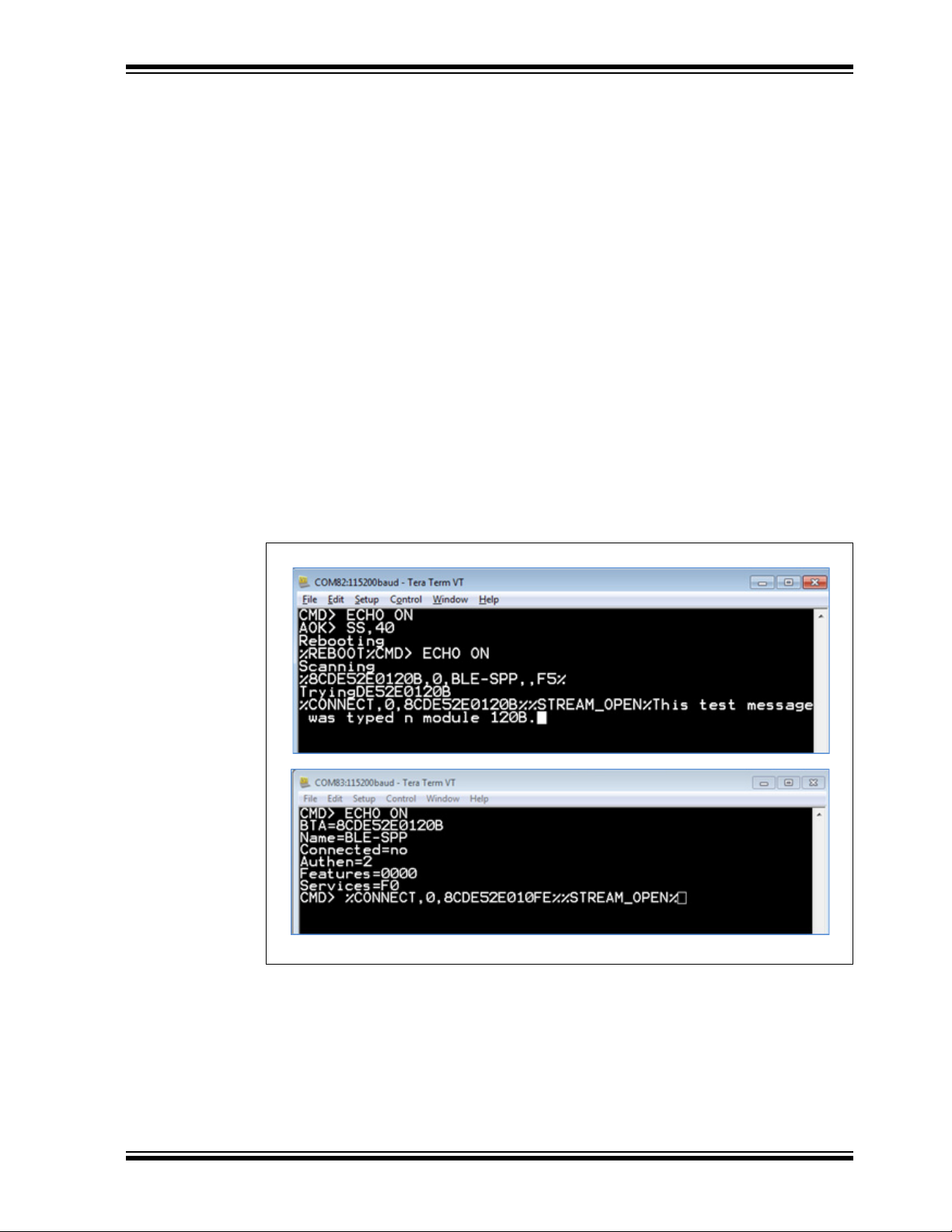
4.3 MODULE TO MODULE CONNECTION
The RN4870 can initiate BLE connection in Central (GAP) mode to another BLE device
supporting the UART Transparent service. The command sequence is as follows:
1. Using a terminal emulator on host PC, open a connection to RN4870 PICtail on
the enumerated COM port.
2. Type $$$ to enter Command mode
3. Type + to enable echo
4. Enter SS,C0 to enable Device Information and UART Transparent service
5. Issue command F to initiate active scan
6. Wait until inquiry finishes and finds the MAC address/address type of the device
to be connected
7. Enter C,<0,1>,<MAC address> to attempt a connection with the remote
device, where the first parameter indicates the address type that can be found in
the inquiry result: 0 for public address, 1 for private address
Once connected, characters typed in the terminal emulator are sent to the remote peer
device, and vice versa.
To kill the connection, type $$$ to return to Command mode, then type command K,1.
Figure 4-7 shows the commands and responses when connecting two RN4870
modules via UART Transparent.
FIGURE 4-7: CONNECTING TWO RN4870 MODULES
2016 Microchip Technology Inc. DS50002466A-page 57
Page 58

RN4870/71 Bluetooth® Low Energy Module User’s Guide
NOTES:
DS50002466A-page 58 2016 Microchip Technology Inc.
Page 59

Appendix A. Bluetooth Low Energy Fundamentals
A.1 INTRODUCTION
When two BTLE devices must be connected, one device must be in Central role and
the other in Peripheral role. The Peripheral device advertises to show its connectable
status, while the Central device scans service advertisements, and if required, initiates
a connection to the Peripheral device. Once connected, either end of the connection
can choose to bond. Once bonded, all security related keys are saved and security process are waived when reconnecting. Bonded peripheral device can only perform direct
advertise, therefore, no longer is able to connect to device other than its bonded peer.
Similar to Bluetooth Classic, BTLE uses the concept of profiles to ensure
interoperability between different devices. As illustrated in Figure A-1, BTLE profiles
are collection of services. All BTLE services are built on top of the Generic Attribute
Profile (GATT), where GATT defines accessibility of attributes called characteristics.
Therefore, the main functionality of the BTLE profiles is built around the characteristics.
Those devices that maintain the value of characteristics in a service are called the
Server of the Service. On the other hand, those devices that acquire data from their
peer are called Client.
Each service and its characteristics can be identified by its UUID. The UUID takes
either a16-bit short form or a 128-bit long form. As specified in the Bluetooth Core Specifications, all Bluetooth SIG adopted public services and characteristics have short
UUIDs, while the user defined private UUIDs are in long form. For the details of Bluetooth SIG adopted services and characteristics, please refer to
https://developer.bluetooth.org/gatt/profiles/Pages/ProfilesHome.aspx.
The accessibility of each characteristic is defined by a 8-bit characteristic property in
bitmap format, as shown in Ta bl e A - 1.
RN4870/71 BLUETOOTH
LOW ENERGY MODULE
USER’S GUIDE
®
TABLE A-1: CHARACTERISTIC PROPERTIES
Property Bitmap Description
Extended Property
Authenticated Write
Indicate 0b00100000 Indicate value of characteristic with acknowledgment
Notify 0b00010000 Notify value of characteristic without acknowledgment
Write 0b00001000 Write value of characteristic with acknowledgment
Write without
response
Read 0b00000010 Read value of characteristic. Value is sent from server
Broadcast
Note 1: Currently not supported in RN4870
2016 Microchip Technology Inc. DS50002466A-page 59
(1)
(1)
0b10000000 Additional property available
(1)
0b01000000 Write characteristic with authentication from client to
server
from server to client
from server to client
from client to server
0b00000100 Write value of characteristic without acknowledgment
from client to server
to client
0b00000001 Broadcast value of characteristic
Page 60

RN4870/71 Bluetooth® Low Energy Module User’s Guide
[GAP Peripheral, GATT Server]
p
p
p
p
[GAP Central, GATT Client]
Central-Client devices
include the following:
x SmartPhone
x Host PC
x Tablet
x RN4020 module
x RN4870 module
x Other BTLE device
GATT Client Write-5(4
GATT Client Read-5(4
ACK-Write-REQ
Read-RESP
GATT Client Write-&0'
ACK-Indication
As shown in Figure A-1, the GATT Client can access the characteristics in the GATT
Server in the peripheral device. When connected, the client reads the GATT Server service and characteristic UUIDs. The characteristic values can be accessed by the GATT
client using Write, Read, Indication and Notifications.
Write-REQ enables client to update characteristic values on the Peripheral's GATT
server. The write requests can be performed using RN4870 CHW and CUW commands.
For more details on GATT characteristic access commands, refer to
Section 2.9 “Characteristic Access Commands”.
A Write-CMD message performs an unacknowledged write from a client to the server.
This is enabled for UART Transparent writes on the RN4870 when SR,0100 command
is used.
A client sends Read-REQ to read a characteristic value on the Peripheral's GATT
server. The write requests can be performed using RN4870 CHR and CUR commands.
Notifications and Indications are unsolicited updates sent from the Server to the Client.
The client must enable the notification and indication on a characteristic to receive the
updates. On the RN870 module, this done by using the CUW or CHW command to write
non-zero value to the Notification Characteristic. When RN4870 in client mode receives
a notification, the %WC,hhhh,ddddddd% message is returned on UART in Command
mode.
FIGURE A-1: GATT SERVICE IN RN4870
RN4870
GATT Server Service
Public Service 16-bit UUID
Characteristic 16-bit UUID
Properties & Descriptors
Characteristic 16-bit UUID
erties & Descriptors
Pro
Characteristic 16-bit UUID
erties & Descriptors
Pro
Private Service 128-bit UUID
Characteristic 128-bit UUID
Properties & Descriptors
Characteristic 16-bit UUID
Pro
erties & Descriptors
Characteristic 128-bit UUID
Pro
erties & Descriptors
GATT Notification
GATT Indication
BTLE Device
DS50002466A-page 60 2016 Microchip Technology Inc.
Page 61

RN4870/71 BLUETOOTH
LOW ENERGY MODULE
USER’S GUIDE
Appendix B. Status Response Summary Quick Reference
B.1 INTRODUCTION
Ta bl e B - 1 lists status messages that can be returned by the module through UART. The
status messages can be emitted in either Data or Command mode. Therefore, it is
important that the MCU sending the data, such as UART Transparent stream, be able
to recognize status messages.
The delimiters of the status messages can be changed using the S% command.
TABLE B-1: STATUS MESSAGES RETURNED BY RN4870
Status Message
Default Delimiter (%)
%ADV_TIMEOUT% Advertisement timeout, if advertisement time is
specified by command A
%BONDED% Security materials such as Link Key has been
saved into NVM
%CONN_PARAM,<Interval>,
<Latency>,<Timeout>%
%CONNECT,<0-1>,<Addr>% Connect to BLE device with address <Addr>
%DISCONNECT% BLE connection lost
%ERR_CONNPARAM% Failed to update connection parameters
%ERR_MEMORY% Running out of dynamic memory
%ERR_READ% Failed to read characteristic value
%ERR_RMT_CMD% Failed to start remote command, due to insecure
%ERR_SEC% Failed to secure the BLE link
%KEY:<Key>% Display the 6-digit security key
%KEY_REQ% Request input security key
%INDI,<hdl>,<hex>% Received value indication <hex> for characteristic
%NOTI,<hdl>,<hex>% Received value notification <hex> for characteristic
%PIO1H% PIO1 rising edge event
%PIO1L% PIO1 falling edge event
%PIO2H% PIO2 rising edge event
%PIO2L% PIO2 falling edge event
%PIO3H% PIO3 rising edge event
%PIO3L% PIO3 falling edge event
%RE_DISCV% Received data indication of service changed, redo
%REBOOT% Reboot finished
%RMT_CMD_OFF% End of Remote Command mode
Update connection parameters of connection
interval, slave latency and supervision timeout.
BLE link or mismatch pin code
handle <hdl>
handle <hdl>
service discovery
Description
®
2016 Microchip Technology Inc. DS50002466A-page 61
Page 62

RN4870/71 Bluetooth® Low Energy Module User’s Guide
TABLE B-1: STATUS MESSAGES RETURNED BY RN4870 (CONTINUED)
Status Message
Default Delimiter (%)
%RMT_CMD_ON% Start of Remote Command mode
%RV,<hdl>,<hex>% Read value <hex> for characteristic handle <hdl>
%S_RUN:<CMD>% Debugging information when running script.
the command called by script
%SECURED% BLE link has been secured
%STREAM_OPEN% UART Transparent data pipe has been established
%TMR1% Timer 1 expired event
%TMR2% Timer 2 expired event
%TMR3% Timer 3 expired event
%WC,<hdl>,<hex>% Received start/end notification/indication request
<hex> for characteristic configuration handle <hdl>
%WV,<hdl>,<hex>% Received write request <hex> for characteristic
handle <hdl>
%<Addr>,<0-1>,<name>,<UUIDs>,
<RSSI>%
%<Addr>,<0-1>,<RSSI>,Brcst,
<hex>%
Received connectable advertisement
Received non-connectable advertisement
Ta bl e B - 2 summarizes the ASCII commands discussed in Chapter 2. “Command
Reference”.
Description
CMD is
TABLE B-2: COMMAND SUMMARY QUICK REFERENCE
ASCII Command Description
Set Commands
S- Set serialized device name
S$ Set configuration detect character
S% Set pre and post delimiter of status string
S: Modify any configurations in Eflash
SA Set Pairing mode
SB Set UART baud rate
SC Set beacon features
SDA Set appearance in GAP service
SDF Set firmware version in Device Info service
SDH Set hardware revision in Device Info service
SDM Set model string in Device Info service
SDN Set manufacturer name in Device Info service
SDR Set software revision in Device Info service
SDS Set serial number in Device Info service
SF,1 Factory Reset
SGA Set RF power in advertisement
SGC Set RF power in connected state
SM Start timer
SN Set device name
SO Set power saving mode
SP Set fix pin for pin code display authentication
SR Set feature
DS50002466A-page 62 2016 Microchip Technology Inc.
Page 63

TABLE B-2: COMMAND SUMMARY QUICK REFERENCE (CONTINUED)
ASCII Command Description
SS Enable default services
ST Set connection parameters for central
SW Assign GPIO functions
Get Commands
G: Read any settings in configuration eFlash
GK Get current connection status
GNR Get remote device name
G<char> Get the stored settings for a corresponding set command.
Action Commands
+ Echo
$$$ Get into Command mode
--- Get into Data mode
! Enter/exit Remote Command mode
@ Read analog port
|I Read digital port
|O Set digital port
[ PWM control
& Static private address assignment
&C Clear random address and use MAC address
&R Create and use a resolvable random address
A Start advertisement
B Start bonding process
C Connect to peer device as central
D Display RN4870 critical information
F Start scanning as central
I Start UART Transparent with RN4020 and RN4677/4678
IA Set advertisement content immediately
IB Set beacon content immediately
IS Set scan response content immediately
JA Add device into white list
JB Add all bonded device into white list
JC Clear white list
JD Display all devices in white list
K,1 Disconnect
M Read RSSI value of connected device
NA Set advertisement content permanently
NB Set beacon content permanently
NS Set scan response content permanently
O Shut down device
R,1 Reset
T Change connection parameters instantly
U Unbond device(s)
V Display firmware version
X Stop scan
Y Stop advertisement
2016 Microchip Technology Inc. DS50002466A-page 63
Page 64

RN4870/71 Bluetooth® Low Energy Module User’s Guide
TABLE B-2: COMMAND SUMMARY QUICK REFERENCE (CONTINUED)
ASCII Command Description
Z Stop connection process
List Commands
LB List all bonded device
LC List all remote services as client
LS List all local services as server
LW List current script
Service Definition
PC Define characteristic
PS Define service UUID
PZ Clear all service definition
Characteristic Access
CHR Read remote characteristic value as client
CHW Write remote characteristic value as client
CI Discover remote services/characteristics as client
SHR Read local characteristic value as server
SHW Write local characteristic value as server
Script Control
WC Clear current script
WP Pause script execution
WR Run script
WW Write script
DS50002466A-page 64 2016 Microchip Technology Inc.
Page 65

Worldwide Sales and Service
AMERICAS
Corporate Office
2355 West Chandler Blvd.
Chandler, AZ 85224-6199
Tel: 480-792-7200
Fax: 480-792-7277
Technical Support:
http://www.microchip.com/
support
Web Address:
www.microchip.com
Atlanta
Duluth, GA
Tel: 678-957-9614
Fax: 678-957-1455
Austin, TX
Tel: 512-257-3370
Boston
Westborough, MA
Tel: 774-760-0087
Fax: 774-760-0088
Chicago
Itasca, IL
Tel: 630-285-0071
Fax: 630-285-0075
Cleveland
Independence, OH
Tel: 216-447-0464
Fax: 216-447-0643
Dallas
Addison, TX
Tel: 972-818-7423
Fax: 972-818-2924
Detroit
Novi, MI
Tel: 248-848-4000
Houston, TX
Tel: 281-894-5983
Indianapolis
Noblesville, IN
Tel: 317-773-8323
Fax: 317-773-5453
Los Angeles
Mission Viejo, CA
Tel: 949-462-9523
Fax: 949-462-9608
New York, NY
Tel: 631-435-6000
San Jose, CA
Tel: 408-735-9110
Canada - Toronto
Tel: 905-673-0699
Fax: 905-673-6509
ASIA/PACIFIC
Asia Pacific Office
Suites 3707-14, 37th Floor
Tower 6, The Gateway
Harbour City, Kowloon
Hong Kong
Tel: 852-2943-5100
Fax: 852-2401-3431
Australia - Sydney
Tel: 61-2-9868-6733
Fax: 61-2-9868-6755
China - Beijing
Tel: 86-10-8569-7000
Fax: 86-10-8528-2104
China - Chengdu
Tel: 86-28-8665-5511
Fax: 86-28-8665-7889
China - Chongqing
Tel: 86-23-8980-9588
Fax: 86-23-8980-9500
China - Dongguan
Tel: 86-769-8702-9880
China - Hangzhou
Tel: 86-571-8792-8115
Fax: 86-571-8792-8116
China - Hong Kong SAR
Tel: 852-2943-5100
Fax: 852-2401-3431
China - Nanjing
Tel: 86-25-8473-2460
Fax: 86-25-8473-2470
China - Qingdao
Tel: 86-532-8502-7355
Fax: 86-532-8502-7205
China - Shanghai
Tel: 86-21-5407-5533
Fax: 86-21-5407-5066
China - Shenyang
Tel: 86-24-2334-2829
Fax: 86-24-2334-2393
China - Shenzhen
Tel: 86-755-8864-2200
Fax: 86-755-8203-1760
China - Wuhan
Tel: 86-27-5980-5300
Fax: 86-27-5980-5118
China - Xian
Tel: 86-29-8833-7252
Fax: 86-29-8833-7256
ASIA/PACIFIC
China - Xiamen
Tel: 86-592-2388138
Fax: 86-592-2388130
China - Zhuhai
Tel: 86-756-3210040
Fax: 86-756-3210049
India - Bangalore
Tel: 91-80-3090-4444
Fax: 91-80-3090-4123
India - New Delhi
Tel: 91-11-4160-8631
Fax: 91-11-4160-8632
India - Pune
Tel: 91-20-3019-1500
Japan - Osaka
Tel: 81-6-6152-7160
Fax: 81-6-6152-9310
Japan - Tokyo
Tel: 81-3-6880- 3770
Fax: 81-3-6880-3771
Korea - Daegu
Tel: 82-53-744-4301
Fax: 82-53-744-4302
Korea - Seoul
Tel: 82-2-554-7200
Fax: 82-2-558-5932 or
82-2-558-5934
Malaysia - Kuala Lumpur
Tel: 60-3-6201-9857
Fax: 60-3-6201-9859
Malaysia - Penang
Tel: 60-4-227-8870
Fax: 60-4-227-4068
Philippines - Manila
Tel: 63-2-634-9065
Fax: 63-2-634-9069
Singapore
Tel: 65-6334-8870
Fax: 65-6334-8850
Taiwan - Hsin Chu
Tel: 886-3-5778-366
Fax: 886-3-5770-955
Taiwan - Kaohsiung
Tel: 886-7-213-7828
Taiwan - Taipei
Tel: 886-2-2508-8600
Fax: 886-2-2508-0102
Thailand - Bangkok
Tel: 66-2-694-1351
Fax: 66-2-694-1350
EUROPE
Austria - Wels
Tel: 43-7242-2244-39
Fax: 43-7242-2244-393
Denmark - Copenhagen
Tel: 45-4450-2828
Fax: 45-4485-2829
France - Paris
Tel: 33-1-69-53-63-20
Fax: 33-1-69-30-90-79
Germany - Dusseldorf
Tel: 49-2129-3766400
Germany - Karlsruhe
Tel: 49-721-625370
Germany - Munich
Tel: 49-89-627-144-0
Fax: 49-89-627-144-44
Italy - Milan
Tel: 39-0331-742611
Fax: 39-0331-466781
Italy - Venice
Tel: 39-049-7625286
Netherlands - Drunen
Tel: 31-416-690399
Fax: 31-416-690340
Poland - Warsaw
Tel: 48-22-3325737
Spain - Madrid
Tel: 34-91-708-08-90
Fax: 34-91-708-08-91
Sweden - Stockholm
Tel: 46-8-5090-4654
UK - Wokingham
Tel: 44-118-921-5800
Fax: 44-118-921-5820
07/14/15
DS50002466A-page 65 2016 Microchip Technology Inc.
 Loading...